HARRIS TR-0103-E MOMENTUM HDT300 DMR TIER III BASE STATION VHF User Manual
HARRIS CORPORATION MOMENTUM HDT300 DMR TIER III BASE STATION VHF
UserManual.wiki
>
HARRIS
>
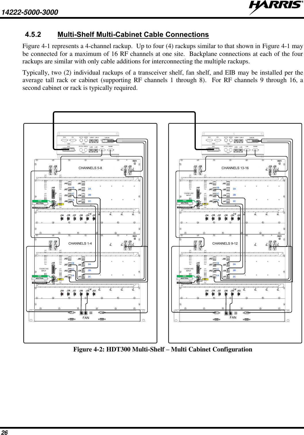
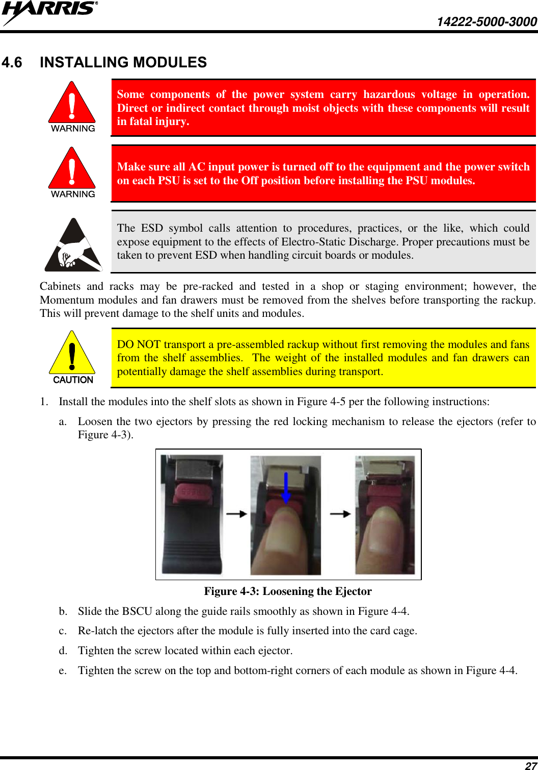
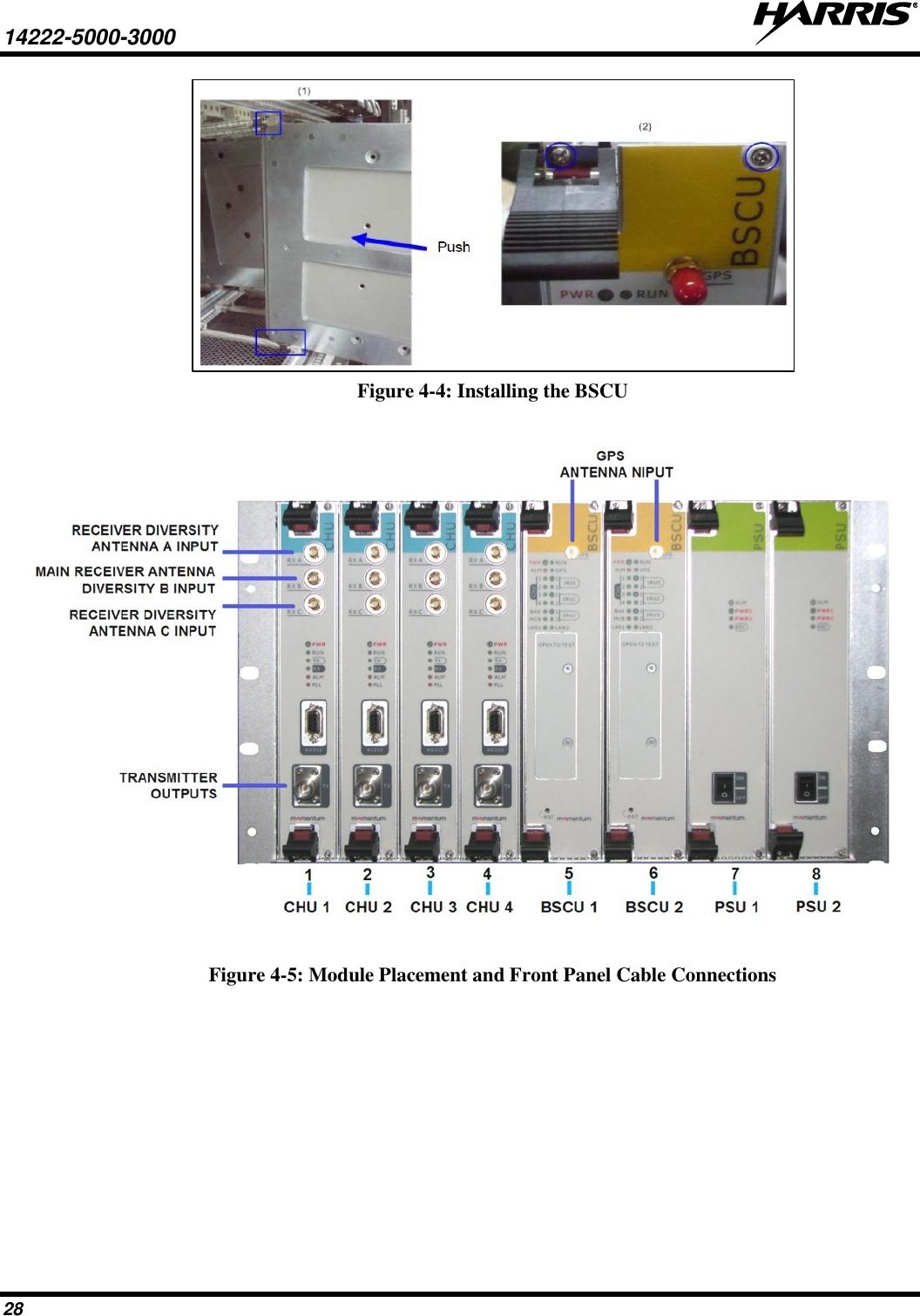
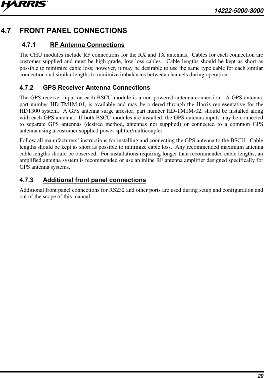
TR 0103 E User Manual
User Manual
Navigation menu
Upload a User Manual
Namespaces
Wiki Guide
HTML
PDF
Info
Views
User Manual
Discussion / Help
Navigation