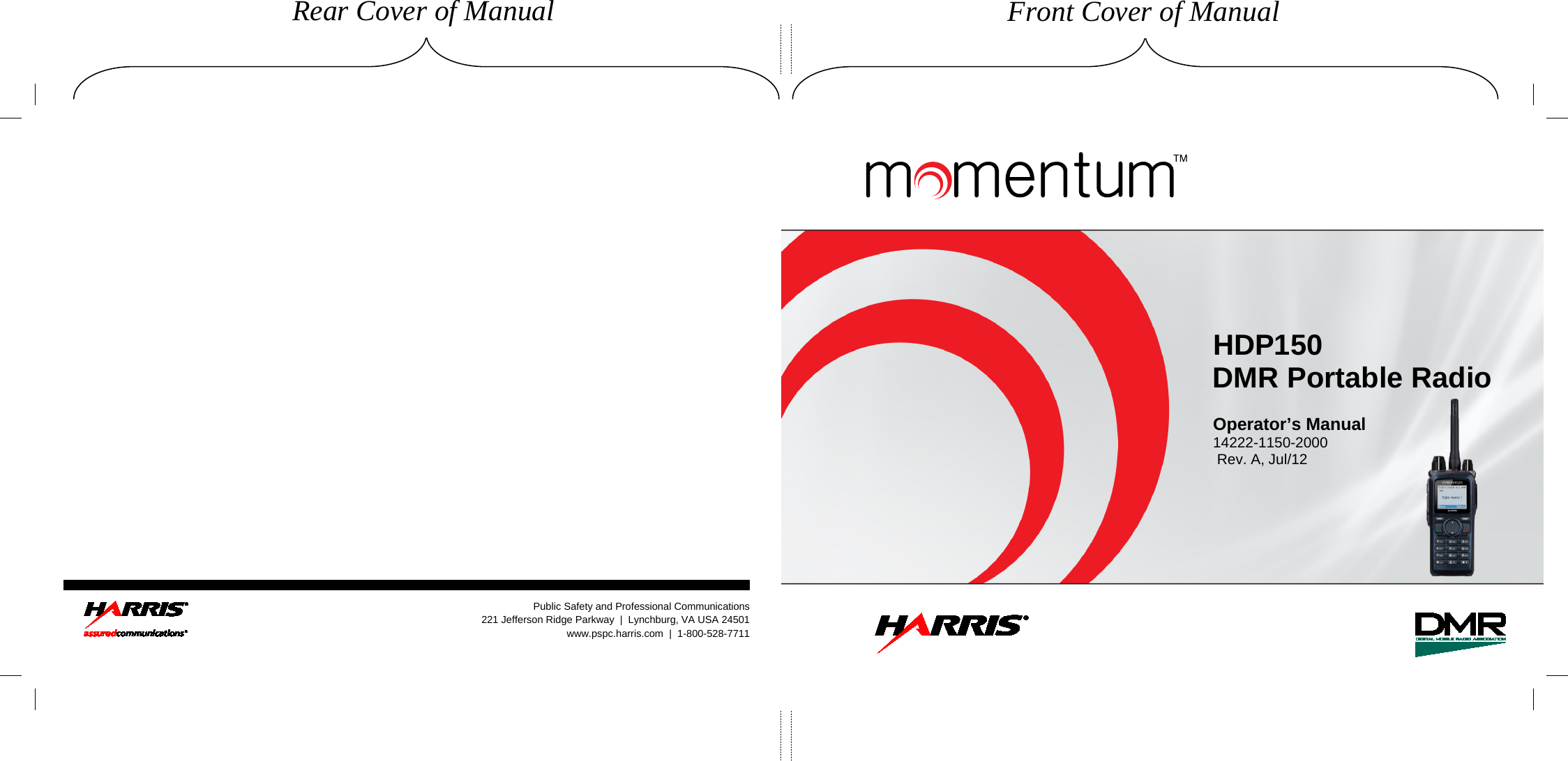
HARRIS TR-0105-E Digital Portable Radio User Manual
HARRIS CORPORATION Digital Portable Radio
UserManual.wiki
>
HARRIS
>
TR 0105 E User Manual
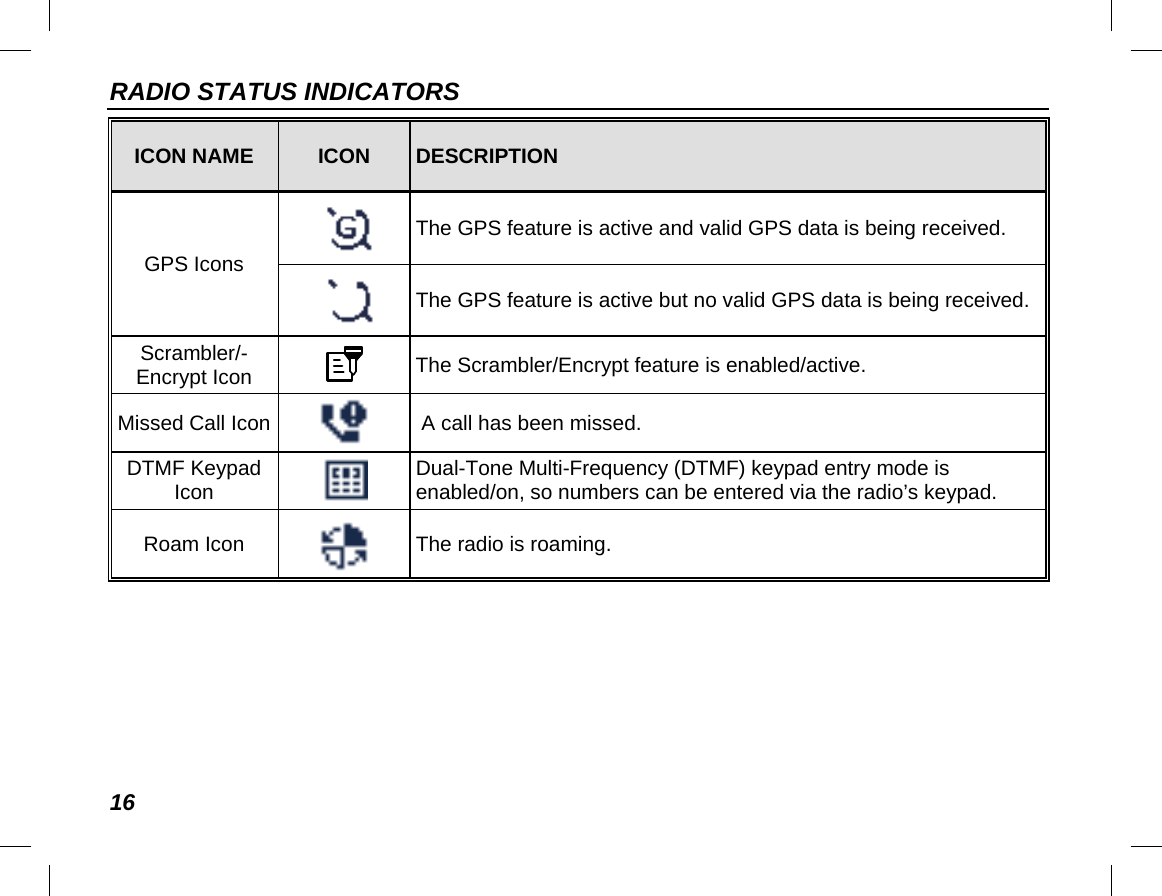
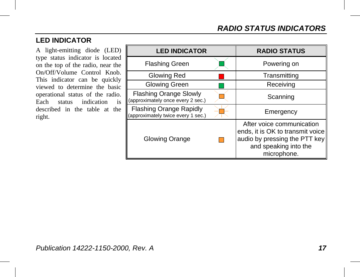
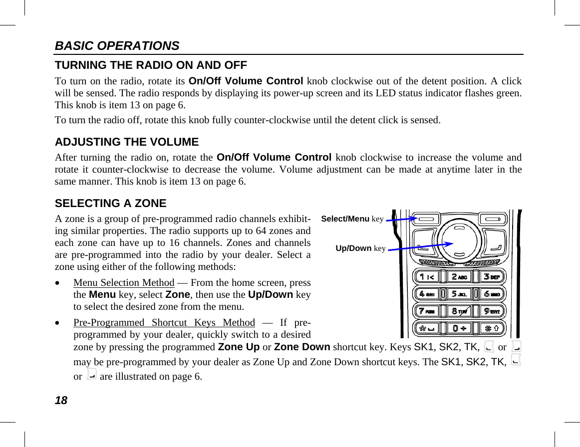
User Manual
Navigation menu
Upload a User Manual
Namespaces
Wiki Guide
HTML
PDF
Info
Views
User Manual
Discussion / Help
Navigation