HARRIS TR-0105-E Digital Portable Radio User Manual
HARRIS CORPORATION Digital Portable Radio
HARRIS >
User Manual


Publication 14222-1150-2000, Rev. A iii
MANUAL REVISION HISTORY
REV. DATE REASON FOR CHANGE
– Nov/11 Initial release.
A Jul/12 Revised attachment procedure for accessory/programming cable and accessory model
numbers. Added Equipment and Rechargeable Battery Warranty.
Harris Corporation, Public Safety and Professional Communications (PSPC) Business continually evaluates its technical
publications for completeness, technical accuracy, and organization. You can assist in this process by submitting your
comments and suggestions to the following:
Harris Corporation fax your comments to: 1-434-455-6851
PSPC Business or email us at:
Technical Publications PSPC_TechPubs@harris.com
221 Jefferson Ridge Parkway
Lynchburg, VA 24501
ACKNOWLEDGEMENT
This device is made under license under one or more of the following US patents: 4,590,473; 4,636,791; 5,148,482;
5,185,796; 5,195,166; 5,271,017; 5,377,229; 4,716,407; 4,972,460; 5,502,767; 5,146,497; 5,164,986; 5,185,795; 5,226,084;
5,247,579; 5,491,772; 5,517,511; 5,581,656; 5,630,011; 5,649,050; 5,701,390; 5,715,365; 5,754,974; 5,826,222; 5,870,405;
6,161,089; 6,199,037 B1 and 6,912,495 B2. DVSI claims certain rights, including patent rights under aforementioned U.S.
patents, and under other U.S. and foreign patents and patents pending. Any use of this software or technology requires a
separate written license from DVSI. CREDITS
Harris and assuredcommunications are registered trademarks of and Momentum is a trademark of Harris Corporation.
NOTICE!
The material contained herein is subject to U.S. export approval. No export or re-export is permitted without written
approval from the U.S. Government. Rated: EAR99 in accordance with U.S. Dept. of Commerce regulations 15CFR774,
Export Administration Regulations.

iv
NOTICE!
Information and descriptions contained herein are the property of Harris Corporation. Such information and descriptions
may not be copied or reproduced by any means, or disseminated or distributed without the express prior written permission
of Harris Corporation, PSPC Business, 221 Jefferson Ridge Parkway, Lynchburg, VA 24501.
The voice coding technology embodied in this product is protected by intellectual property rights including patent rights,
copyrights, and trade secrets of Digital Voice Systems, Inc. The user of this technology is explicitly prohibited from
attempting to decompile, reverse engineer, or disassemble the Object Code, or in any other way convert the Object Code
into human-readable form.
Repairs to this equipment should be made only by an authorized service technician or facility designated by the supplier.
Any repairs, alterations or substitutions of recommended parts made by the user to this equipment not approved by the
manufacturer could void the user's authority to operate the equipment in addition to the manufacturer's warranty.
This product conforms to the European Union WEEE Directive 2002/96/EC. Do not dispose of this product in
a public landfill. Take it to a recycling center at the end of its life.
This manual is published by Harris Corporation without any warranty. Improvements and changes to this manual necessitated by typographical errors,
inaccuracies of current information, or improvements to programs and/or equipment, may be made by Harris Corporation
at any time and without notice.
Such changes will be incorporated into new editions of this manual. No part of this manual may be reproduced or transmitted i
n any form or by any means,
electronic or mechanical, including photocopying and recording, for any purpose, without the express written permission of Harris Corporation.
Copyright© 2011 — 2012, Harris Corporation

TABLE OF CONTENTS
Publication 14222-1150-2000, Rev. A v
Section Page
SYMBOLS USED IN THIS MANUAL .................................................................................................................. 1
CAUTION AND NOTE SYMBOLS ................................................................................................................. 1
SYMBOLS FOR ANALOG AND DIGITAL CHANNEL FEATURES/FUNCTIONS .................................... 1
REGULATORY INFORMATION ........................................................................................................................ 2
PRODUCT SAFETY BOOKLET ..................................................................................................................... 2
RF EXPOSURE GUIDELINES ......................................................................................................................... 2
ELECTROMAGNETIC INTERFERENCE ...................................................................................................... 3
FCC Part 15 Statement ............................................................................................................................... 4
Industry Canada Statement ......................................................................................................................... 4
EU REGULATORY CONFORMANCE ........................................................................................................... 4
CHECKING ITEMS IN THE PACKAGE ............................................................................................................ 5
RADIO OVERVIEW ............................................................................................................................................... 6
RADIO CONTROLS, INDICATORS, AND OTHER ITEMS.......................................................................... 6
PROGRAMMABLE SHORTCUT KEYS ......................................................................................................... 7
BEFORE USING THE RADIO ............................................................................................................................ 10
CHARGING THE BATTERY......................................................................................................................... 10
ASSEMBLY AND DISASSEMBLY .............................................................................................................. 11
Attaching and Removing the Antenna ...................................................................................................... 11
Attaching the Battery ................................................................................................................................ 11
Removing the Battery ............................................................................................................................... 11
Attaching the Belt Clip ............................................................................................................................. 12
Removing the Belt Clip ............................................................................................................................ 12
Attaching the Audio Accessory/Programming Cable ............................................................................... 12
Removing an Accessory/Programming Cable .......................................................................................... 13
RADIO STATUS INDICATORS ......................................................................................................................... 14
OPERATIONAL MODE AND STATUS ICONS THE DISPLAY ................................................................ 14
LED INDICATOR ........................................................................................................................................... 17

TABLE OF CONTENTS
vi
Section Page
BASIC OPERATIONS ......................................................................................................................................... 18
TURNING THE RADIO ON AND OFF ........................................................................................................ 18
ADJUSTING THE VOLUME ........................................................................................................................ 18
SELECTING A ZONE .................................................................................................................................... 18
SELECTING A CHANNEL ........................................................................................................................... 19
SWITCHING THE CHANNEL MODE BETWEEN ANALOG AND DIGITAL ......................................... 19
LOCKING AND UNLOCKING THE KEYPAD ........................................................................................... 19
HOME SCREEN ............................................................................................................................................. 20
PRIVATE CALLS .................................................................................................................................. 20
Transmitting a Private Call ...................................................................................................................... 20
Receiving and Responding to a Private Call ............................................................................................ 22
GROUP CALLS ..................................................................................................................................... 23
Transmitting a Group Call ....................................................................................................................... 23
Receiving and Responding to a Group Call ............................................................................................. 24
ALL CALLS ........................................................................................................................................... 25
Transmitting an All Call .......................................................................................................................... 25
Receiving an All Call ............................................................................................................................... 25
TALK-AROUND (DIRECT MODE) ............................................................................................................. 25
CALLS ON ANALOG CHANNELS ..................................................................................................... 26
Transmitting a Call on an Analog Channel .............................................................................................. 26
Receiving a Call on an Analog Channel .................................................................................................. 26
Monitor .................................................................................................................................................... 26
Squelch Off .............................................................................................................................................. 27
Telephone Interconnect Calls .................................................................................................................. 27
BATTERY STRENGTH INDICATOR .......................................................................................................... 29
MENU NAVIGATION ......................................................................................................................................... 30
MAIN MENU ................................................................................................................................................. 30
CONTACT MENU ................................................................................................................................. 30

TABLE OF CONTENTS
Publication 14222-1150-2000, Rev. A vii
Section Page
Contact List .............................................................................................................................................. 30
New Contact ............................................................................................................................................. 31
Manual Dial .............................................................................................................................................. 31
MESSAGE MENU .................................................................................................................................. 32
New Msg .................................................................................................................................................. 32
Quick Text ................................................................................................................................................ 32
InBox ........................................................................................................................................................ 32
OutBox ..................................................................................................................................................... 32
Drafts ........................................................................................................................................................ 33
CALL LOGS MENU ............................................................................................................................... 33
PHONE MENU ............................................................................................................................................... 34
Phone List ................................................................................................................................................. 34
Manual Dial .............................................................................................................................................. 34
DTMF Keypad ......................................................................................................................................... 34
ROAMING MENU .......................................................................................................................................... 34
SCAN MENU .................................................................................................................................................. 35
Scan On/Off .............................................................................................................................................. 35
Scan List ................................................................................................................................................... 35
ZONE MENU .................................................................................................................................................. 36
SETTINGS MENU .......................................................................................................................................... 36
Radio Set .................................................................................................................................................. 36
Device Info ............................................................................................................................................... 39
ACCESSORIES MENU .................................................................................................................................. 40
GPS .......................................................................................................................................................... 40
SCANNING CHANNELS ..................................................................................................................................... 42
GENERAL INFORMATION .......................................................................................................................... 42
OPERATION ................................................................................................................................................... 42
Turning Scan On and Off ......................................................................................................................... 42
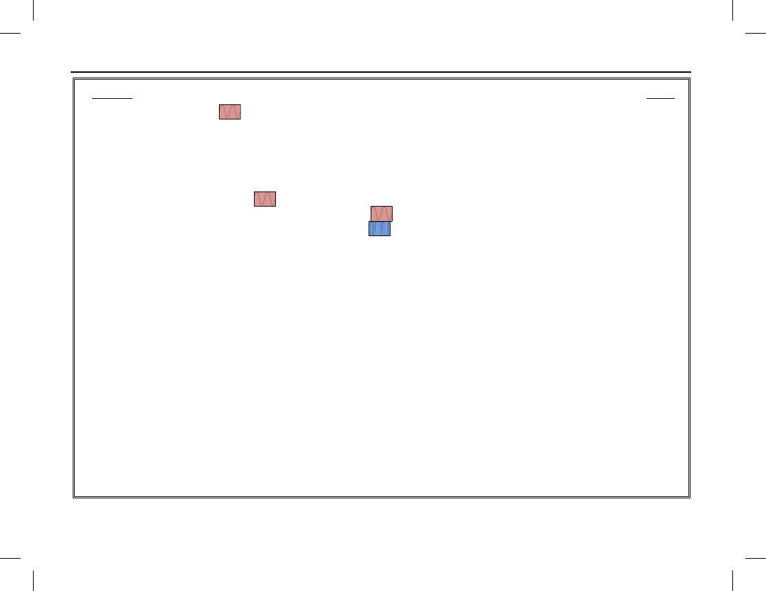
TABLE OF CONTENTS
viii
Section Page
Pausing Scan ................................................................................................................................... 43
Nuisance Temporary Delete .................................................................................................................... 43
EMERGENCY COMMUNICATIONS ............................................................................................................... 44
GENERAL INFORMATION ......................................................................................................................... 44
Emergency Mode ..................................................................................................................................... 44
Emergency Type ...................................................................................................................................... 45
Emergency ID Type ........................................................................................................................ 45
Emergency Operations on Analog Channels ................................................................................... 46
Emergency Operations on Digital Channels .................................................................................... 48
LONE WORKER ............................................................................................................................................ 50
Enabling and Disabling Lone Worker ..................................................................................................... 50
Using Lone Worker ................................................................................................................................. 51
MAN DOWN (OPTIONAL) ........................................................................................................................... 52
Manually Enabling and Disabling Man Down ......................................................................................... 52
Using Man Down ..................................................................................................................................... 52
HDC1200 SIGNALING ........................................................................................................................................ 53
GENERAL INFORMATION ......................................................................................................................... 53
TRANSMISSION (ENCODE) ........................................................................................................................ 53
PTT ID Transmission .............................................................................................................................. 53
Private/Group/All Call Transmission (Selective Call via Contact List) ................................................... 53
RECEPTION (DECODE) ............................................................................................................................... 54
Indications for Received PTT IDs ........................................................................................................... 54
Indications for Received Private/Group/All Calls.................................................................................... 54
SECURE COMMUNICATIONS ......................................................................................................................... 55
GENERAL INFORMATION ......................................................................................................................... 55
OPERATION .................................................................................................................................................. 55
Manually Enabling and Disabling Scrambler/Encrypt ............................................................................. 55

TABLE OF CONTENTS
Publication 14222-1150-2000, Rev. A ix
Section Page
MISCELLANEOUS FEATURES ........................................................................................................................ 56
CHANNEL BUSY LOCKOUT ....................................................................................................................... 56
TIME-OUT TIMER (TOT) .............................................................................................................................. 56
PSEUDO TRUNKING ............................................................................................................................ 56
MIC AGC ........................................................................................................................................................ 56
RADIO REGISTRATION SERVICE ..................................................................................................... 57
GPS REVERT ......................................................................................................................................... 57
ONE TOUCH CALL ....................................................................................................................................... 57
One Touch Call Operation ........................................................................................................................ 57
TELEMETRY ......................................................................................................................................... 58
Supervise a Device via Another/Remote Radio ........................................................................................ 58
Supervise a Device via Third-Party Software ........................................................................................... 58
ROAM ..................................................................................................................................................... 58
5-TONE SIGNALING ..................................................................................................................................... 59
5-Tone Signaling Encode ......................................................................................................................... 59
5-Tone Signaling Decode ......................................................................................................................... 59
2-TONE SIGNALING ..................................................................................................................................... 60
2-Tone Signaling Encode ......................................................................................................................... 60
2-Tone Signaling Decode ......................................................................................................................... 60
ENTERING LETTERS, NUMBERS, AND OTHER CHARACTERS VIA THE KEYPAD ......................... 60
Upper and Lower Case Letters ................................................................................................................. 60
Numbers ................................................................................................................................................... 61
Punctuation Characters and Special Characters ........................................................................................ 61
TROUBLESHOOTING AND TECHNICAL ASSISTANCE ............................................................................ 62
TROUBLESHOOTING TABLE ..................................................................................................................... 62
TECHNICAL ASSISTANCE .......................................................................................................................... 64
CARE AND CLEANING ...................................................................................................................................... 65
RADIO CARE ................................................................................................................................................. 65

TABLE OF CONTENTS
x
Section Page
RADIO CLEANING ....................................................................................................................................... 65
MODEL NUMBERS ............................................................................................................................................. 66
RADIO PACKAGES ...................................................................................................................................... 66
ANTENNAS ................................................................................................................................................... 67
BATTERIES AND BATTERY CHARGERS ................................................................................................ 68
CARRYING ACCESSORIES ......................................................................................................................... 68
AUDIO ACCESSORIES ................................................................................................................................ 69
WARRANTY REGISTRATION AND WARRANTY ....................................................................................... 70
WARRANTY REGISTRATION .................................................................................................................... 70
EQUIPMENT AND RECHARGEABLE BATTERY WARRANTY ............................................................. 70
SYMBOLS USED IN THIS MANUAL
Publication 14222-1150-2000, Rev. A 1
The following tables list symbols used in this manual. These symbols do not appear in the radio’s display.
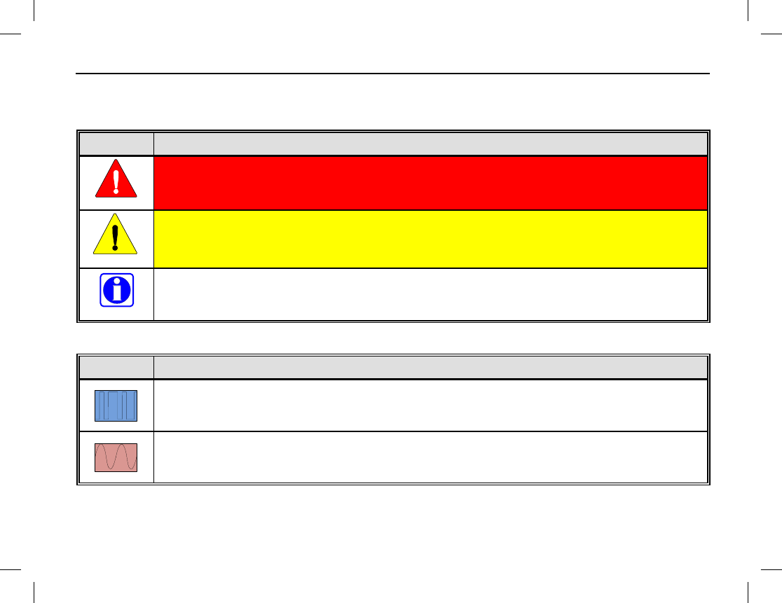
CAUTION AND NOTE SYMBOLS
SYMBOL DESCRIPTION
The WARNING
symbol calls attention to a procedure, practice, or the like, which, if not
correctly performed or adhered to, could result in personal injury. Do not proceed beyond a
WARNING symbol until the conditions identified are fully understood or met.
The CAUTION
symbol calls attention to an operating procedure, practice, or the like, which, if
not performed correctly or adhered to, could result in damage to the equipment or severely
degrade equipment performance.
The NOTE
symbol calls attention to supplemental information, which may improve system
performance or clarify a process or procedure. It may also be used to flag tips that can help you
make better use of the radio.
SYMBOLS FOR ANALOG AND DIGITAL CHANNEL FEATURES/FUNCTIONS
SYMBOL DESCRIPTION
The DIGITAL CHANNEL symbol indicates the particular feature or function applies
to digital
channels only.
The ANALOG CHANNEL symbol indicates the particular feature or function applies to
analog
channels only.
If no digital channel or analog channel symbol appears, the function/feature applies to both analog channels and
digital channels.
WARNING
CAUTION
NOTE

REGULATORY INFORMATION
2
PRODUCT SAFETY BOOKLET
Before operating the HDP150 portable radio, read the safety and RF exposure guidelines
contained in Product Safety Booklet included with the radio.
RF EXPOSURE GUIDELINES
The HDP150 portable radio generates RF electromagnetic energy during transmit mode.
This radio is designed for and classified as “Occupational Use Only,” meaning it must be
used only during the course of employment by individuals aware of the hazards and the
ways to minimize
such hazards. This radio is NOT intended for use by the “General
Population” in an uncontrolled environment.
The HDP150 radio has been tested and complies with the Federal Communications Commission (FCC) RF
exposure limits for “Occupational Use Only.” In addition, this radio complies with the following Standards and
Guidelines with regard to RF energy and electromagnetic energy levels and evaluation of such levels for
exposure to humans:
• FCC Office of Engineering and Technology (OET) Bulletin 65 Edition 97-01 Supplement C, Evaluating
Compliance with FCC Guidelines for Human Exposure to Radio Frequency Electromagnetic Fields.
• American National Standards Institute (C95.1 – 1992), IEEE Standard for Safety Levels with Respect to
Human Exposure to Radio Frequency Electromagnetic Fields, 3 kHz to 300 GHz.
• American National Standards Institute (C95.3 – 1992), IEEE Recommended Practice for the Measurement
of Potentially Hazardous Electromagnetic Fields – RF and Microwave.
WARNING
WARNING

REGULATORY INFORMATION
Publication 14222-1150-2000, Rev. A 3
To ensure exposure to RF electromagnetic energy is within the FCC allowable limits for
occupational use, always adhere to the following guidelines:
• DO NOT operate the radio without a proper antenna attached, as this may damage the radio and may also
cause the FCC RF exposure limits to be exceeded. A proper antenna is the antenna supplied with this radio
by Harris or an antenna specifically authorized by Harris for use with this radio. These antennas are listed
on page 67.
• DO NOT transmit for more than 50% of total radio use time (“50% duty cycle”). Transmitting more than
50% of the time can cause FCC RF exposure compliance requirements to be exceeded. The radio is
transmitting when the LED indicator on the top of the radio lights red in color. The radio transmits when its
“PTT” (Push-To-Talk) key is pressed.
• Always transmit using low power when possible. In addition to conserving battery charge, low power can
reduce RF exposure. Refer to page 36 for additional information.
• ALWAYS use Harris authorized accessories (antennas, batteries, belt clips, speaker/mics, etc). Use of
unauthorized accessories may cause the FCC Occupational/Controlled Exposure RF compliance
requirements to be exceeded.
• ALWAYS keep the device and its antenna at least 1 inch (2.5 centimeters) from the body and face when
transmitting to ensure FCC RF exposure compliance requirements are not exceeded. To provide the best
sound quality to the recipients of your transmission, Harris recommends holding the front of the radio
between 1 and 2 inches (2.5 to 5.0 centimeters) from your mouth when transmitting into the radio’s
microphone.
ELECTROMAGNETIC INTERFERENCE
During transmissions, this radio generates RF energy that can possibly cause interference with other devices or
systems. To avoid such interference, turn off the radio in areas where signs are posted to do so. DO NOT
CAUTION

REGULATORY INFORMATION
4
operate the transmitter in areas that are sensitive to electromagnetic radiation such as hospitals, aircraft, and
blasting sites.
FCC Part 15 Statement
This device complies with Part 15 of the FCC Rules. Operation is subject to the following two conditions:
1. This device may not cause harmful interference, and
2. This device must accept any interference received, including interference that may cause undesired
operation.
Industry Canada Statement
This device complies with Industry Canada license-exempt RSS standard(s). Operation is subject to the
following two conditions: (1) this device may not cause interference, and (2) this device must accept any
interference, including interference that may cause undesired operation of the device.
Le présent appareil est conforme aux CNR d'Industrie Canada applicables aux appareils radio exempts de
licence. L'exploitation est autorisée aux deux conditions suivantes : (1) l'appareil ne doit pas produire de
brouillage, et (2) l'utilisateur de l'appareil doit accepter tout brouillage radioélectrique subi, même si le
brouillage est susceptible d'en compromettre le fonctionnement.
EU REGULATORY CONFORMANCE
As certified by the qualified laboratory, the product is in compliance with the essential requirements and other
relevant provisions of the Directive 1999/5/EC. Please note that the above information is applicable to EU
countries only.
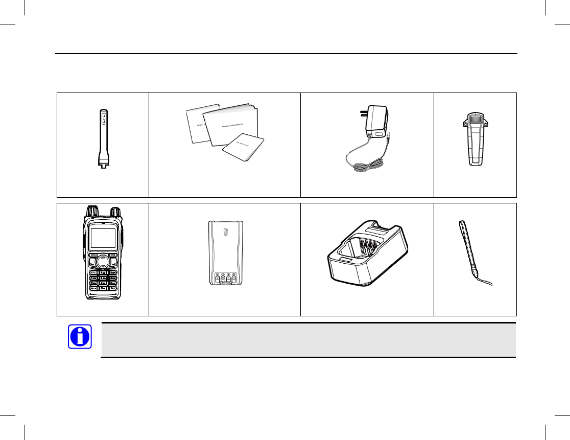
CHECKING ITEMS IN THE PACKAGE
Publication 14222-1150-2000, Rev. A 5
Carefully unpack and check that all items listed below are received. If any item is missing or damaged, please
immediately contact your dealer.
Antenna
Operator’s Manual, Product
Safety Booklet, Quick Guide
Power Adapter
Belt Clip
Radio
Battery
Battery Charger
Wrist Strap
The antenna may vary with different frequency bands. The frequency band is marked on the label
of antenna. If not, refer to the label on the radio unit for frequency band information.
NOTE
RADIO OVERVIEW
6
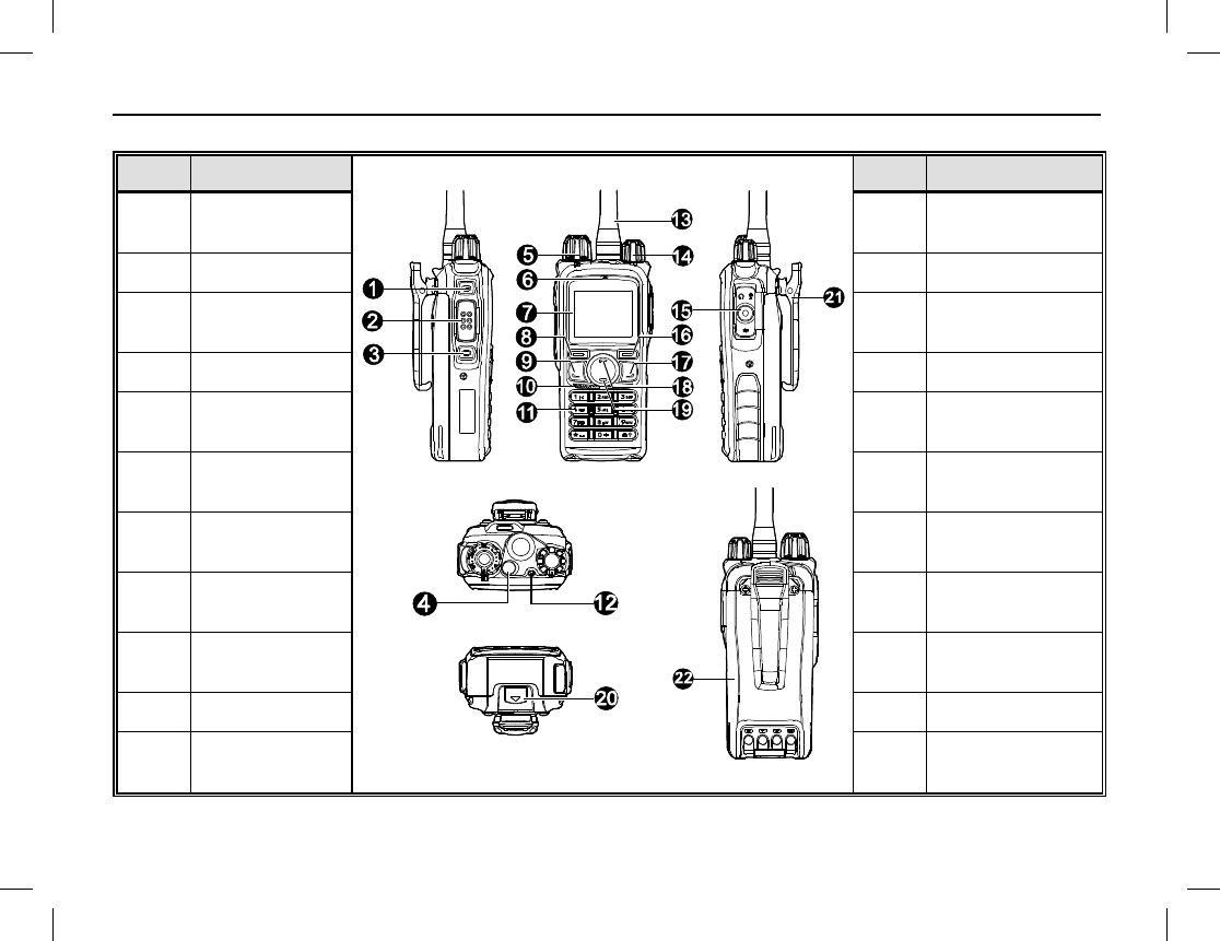
RADIO CONTROLS, INDICATORS, AND OTHER ITEMS
ITEM NAME
ITEM NAME
1 Side Key 1
(SK1) 12 LED Indicator
2 PTT Key 13 Antenna
3 Side Key 2
(SK2) 14 On/Off/Volume
Control Knob
4 Top Key (TK) 15 Accessory Jack
5 Channel
Selector Knob 16 Back Key
6 Microphone 17 Programmable
Key (Right)
7 Liquid Crystal
Display (LCD) 18 Up Key
8 Select/Menu
Key 19 Down Key
9 Programmable
Key (Left) 20 Battery Latch
10 Speaker 21 Belt Clip
11 Keypad 22 Battery
RADIO OVERVIEW
Publication 14222-1150-2000, Rev. A 7
(Table Continued on Next Page)
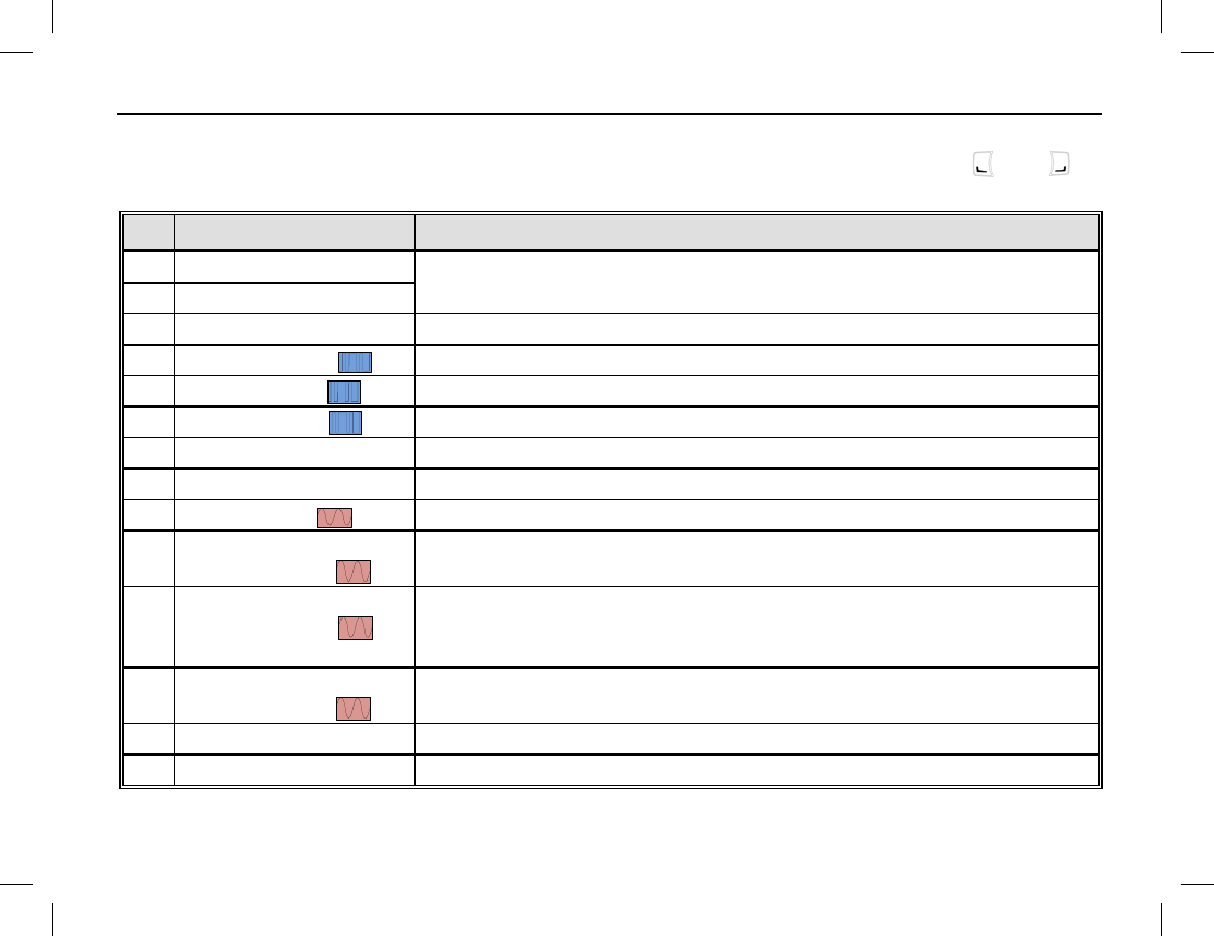
PROGRAMMABLE SHORTCUT KEYS
For enhanced convenience, you may request your dealer pre-program keys SK1, SK2, TK, and as
shortcuts to any of the functions listed in this table:
NO. SHORTCUT NAME SHORTCUT KEY FUNCTION
1 Zone Up Change to another zone. See pages 18 or 36.
2 Zone Down
3 Keypad Lock Lock or unlock the keypad. See page 19.
4 Contact List Quick access the Contact list. See page 30.
5 Message Quick access to Message menu. See page 31.
6 Call Logs Quick access to Call Logs menu. See page 33.
7 Adjust Power Level Quickly change the radio’s transmitting power level. See page 36.
8 Talk-Around Directly communicate with other radios. See page 25.
9 Monitor Toggle receiver muting on and off. See page 26.
10 Monitor
Momentary Momentarily turn receiver muting off. See page 26.
11 Squelch Off Toggle squelch on and off. When off, the radio always unmutes so if
no radio carrier is present on the channel, receiver noise is heard.
See page 27.
12 Squelch Off
Momentary Momentarily turn squelch off. Otherwise, same as above. See page
27.
13 Home Screen Quickly return to the previous menu or home screen. See page 20.
14 Scan Enable and disable scanning. See page 42.
RADIO OVERVIEW
8
(Table Continued on Next Page)
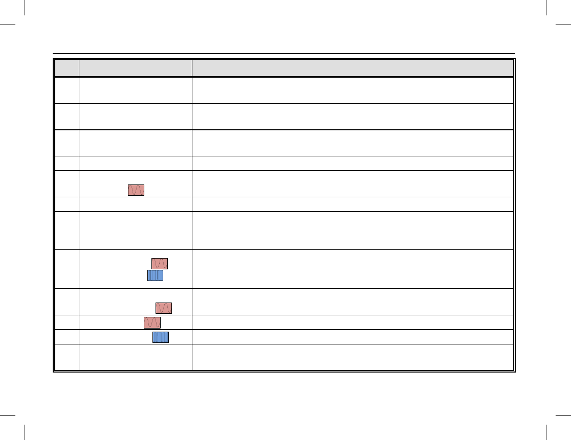
NO. SHORTCUT NAME SHORTCUT KEY FUNCTION
15 Nuisance Temporary
Delete Temporarily skip unwanted channel activity during scanning. See
page 43.
16 Emergency On Turn on the emergency mode and transmit emergency call/signaling.
See page 44.
17 Emergency Off Turn off the emergency call/signaling, exiting emergency mode. See
page 44.
18 Lone Worker Toggle the Lone Worker feature on and off. See page 50.
18 Adjust Squelch Level
Temporarily adjust the receiver squelch threshold. See page 36.
19 Battery Strength Indicator Display remaining battery strength. See page 29.
20 Man Down
(Optional Feature)
Activate this emergency feature so if the radio is positioned at an
angle for a preset period of time, it will begin emergency
transmissions. See page 52.
21 Scrambler /
Encrypt
Scrambler: Encrypt voice transmissions for secure communications.
Encrypt: Encrypt voice and message transmissions for secure
communications. See page 53.
22 One Touch Call
(1 though 5) Quickly make calls or send messages. See pages 57, 59, and 60.
23 Status Quickly access the Status List menu.
24 Telemetry To supervise remote devices. See page 58.
25 DTMF Keypad To enter or exit DTMF keypad mode. In this mode, phone numbers
can be entered via the radio’s keypad. See pages 24, 27, and 34.
RADIO OVERVIEW
Publication 14222-1150-2000, Rev. A 9
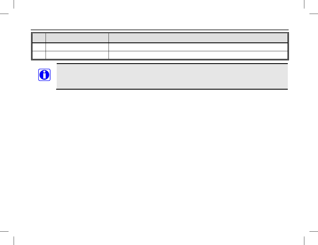
NO. SHORTCUT NAME SHORTCUT KEY FUNCTION
26 Phone List To access the Phone List menu quickly. See pages 27 or 34.
27 Roam To enable and disable the Roam feature. See page 58.
Long and short presses of a key can be programmed with different functions by your dealer.
The Top Key (TK) is programmed as the emergency key by default. It may be reprogrammed by
your dealer.
NOTE
BEFORE USING THE RADIO
10
To achieve optimal battery
performance, charge the
battery five (5) hours
before its initial use.
NOTE
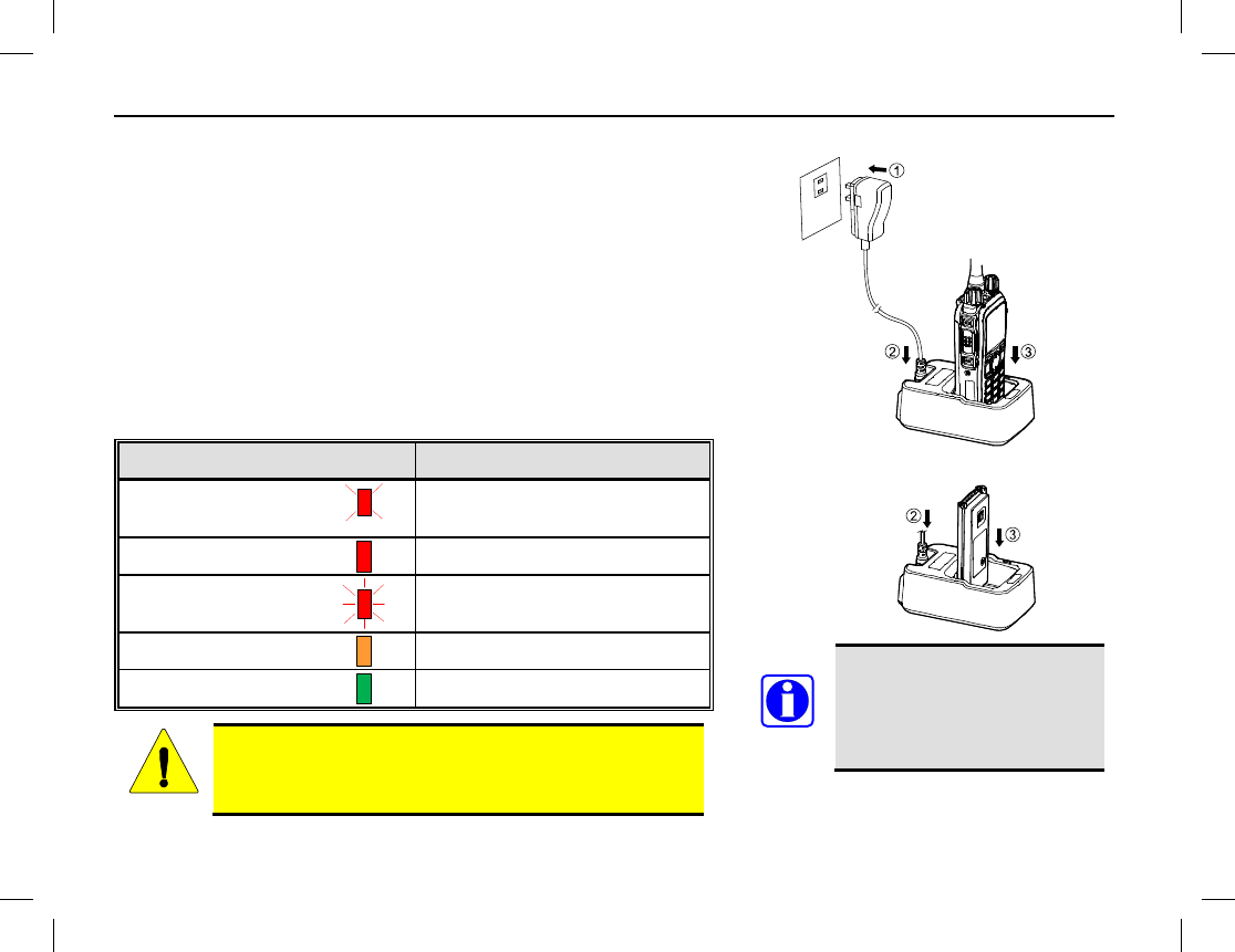
CHARGING THE BATTERY
Follow this procedure to charge the radio’s battery:
1. Connect the AC power adapter to an AC power source. See
arrow .
2. Plug the small plug of the power adapter into the jack at the
rear of the charger. See arrow .
3. Place the radio with the battery attached, or just the battery
alone, into the slot in the top of the charger. See arrow .
4. Refer to the following table for charge status, as indicated by
the charger’s status indicator.
STATUS INDICATOR CHARGE STATUS
Flashes Red
Slowly Standby
(No Load/No Battery)
Glows Red
Battery Charging
Flashes Red
Rapidly
Battery or Charger Failure
Glows Orange
Battery 90% Charged
Glows Green
Battery Fully Charged
Read the radio’s Product Safety Booklet for related
information.
CAUTION
BEFORE USING THE RADIO
Publication 14222-1150-2000, Rev. A 11
Attach
Remove
ASSEMBLY AND DISASSEMBLY
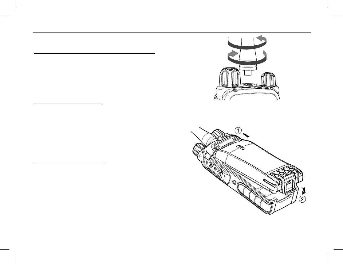
Attaching and Removing the Antenna
To attach the antenna to the radio, place its base into the antenna
jack on the top of the radio and turn the antenna in a clockwise
direction.
To remove the antenna from the radio, simply turn the antenna in
a counter-clockwise direction until it is free from the radio.
Attaching the Battery
To attach the battery to the radio:
1. Slide the top of the battery completely into the cavity
at the rear of the radio. See arrow .
2. Gently press on the bottom of the battery until a click
is heard. See arrow . This locks the battery to the
radio.
Removing the Battery
To remove the battery from the radio:
1. Turn off the radio by rotating it’s on/off/volume
control to the full counter-clockwise position.
2. Grasp the radio firmly in one hand in a bottoms-up
position.
3. Using the other hand, slide the battery latch up to
unlatch the battery, and remove the battery from the
radio.
BEFORE USING THE RADIO
12
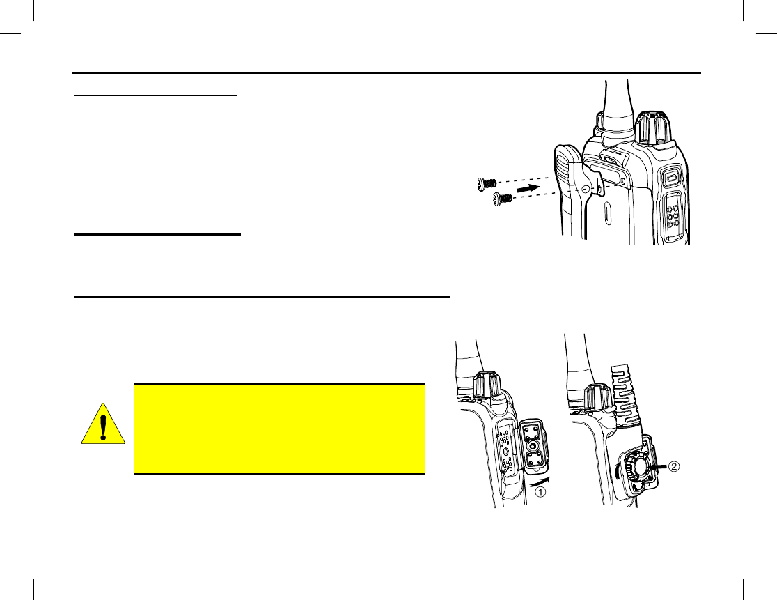
Attaching the Belt Clip
To attach the belt clip to the radio:
1. Remove the two (2) screws on the rear of the radio.
2. As illustrated, align the screw holes on the belt clip with those
on the radio and re-install the two screws into the holes.
3. Using a small screwdriver, tighten the two screws securely. Do
not over-tighten them.
Removing the Belt Clip
To remove the belt clip, use a small screwdriver to loosen and
remove the two (2) screws that secure the clip to the radio, and then remove the it from the radio.
Attaching the Audio Accessory/Programming Cable
To attach an audio accessory or a programming cable to the radio:
1. Open the accessory jack cover, as illustrated by arrow .
2. Align the threaded portion of the cable’s screw with the
threaded hole in the center of the jack.
Do not scrape the silicon rubber on the accessory
jack. Scrapes/Scratches in this area could perma-
nently affect the waterproof performance of the
radio. Correct and incorrect alignment is
shown in the illustration on the next page.
3. Join the screw to the thread hole and tighten the screw by
the knob on the cable’s plug. See arrow .
CAUTION
BEFORE USING THE RADIO
Publication 14222-1150-2000, Rev. A 13
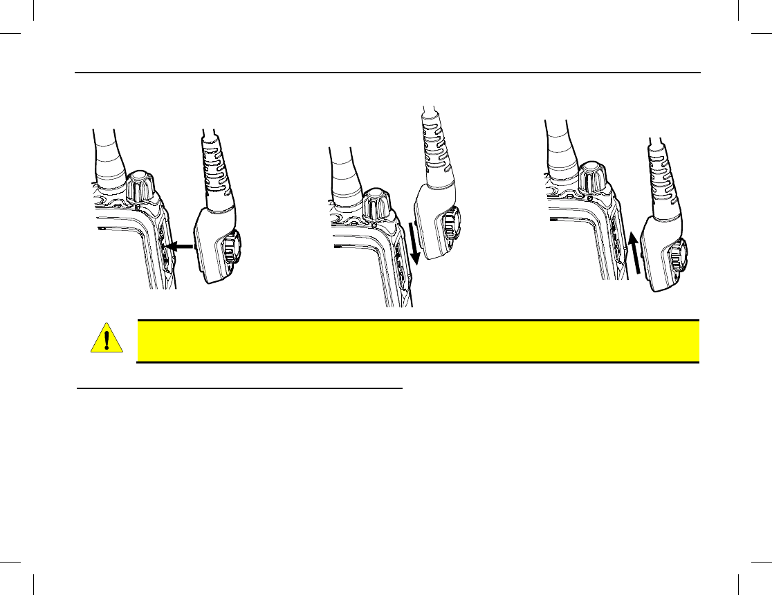
CORRECT INCORRECT INCORRECT
ALIGNMENT ALIGNMENT ALIGNMENT
When an external accessory is attached to the radio’s accessory jack, waterproof performance of
the radio may be affected.
Removing an Accessory/Programming Cable
To remove a cable from the radio’s accessory jack, simply loosen its screw and detach the cable from the jack.
CAUTION
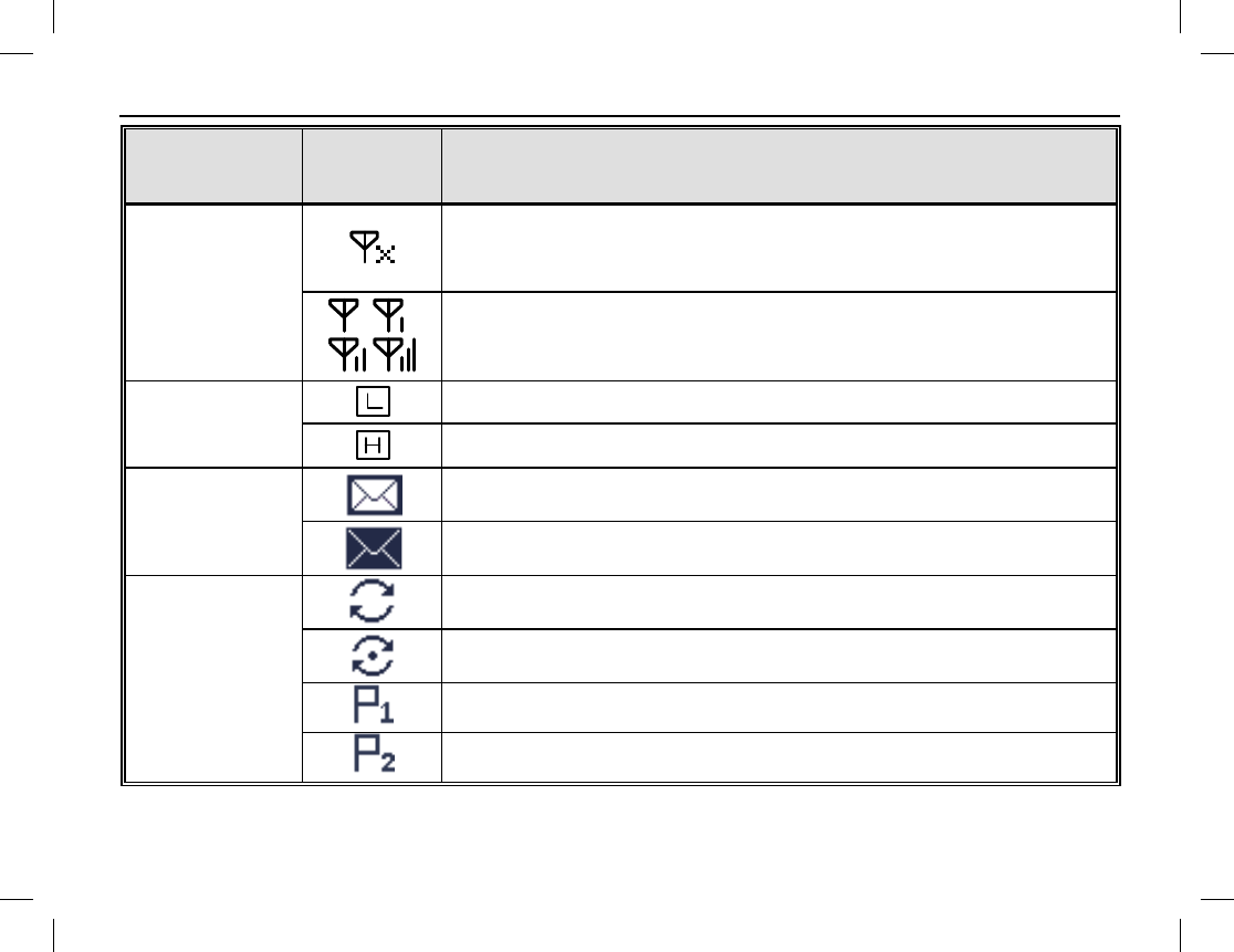
RADIO STATUS INDICATORS
14
OPERATIONAL MODE AND STATUS ICONS THE DISPLAY
The radio has two (2) operational mode icons and multiple status icons that appear in its display. These icons
are illustrated and described in the following table.
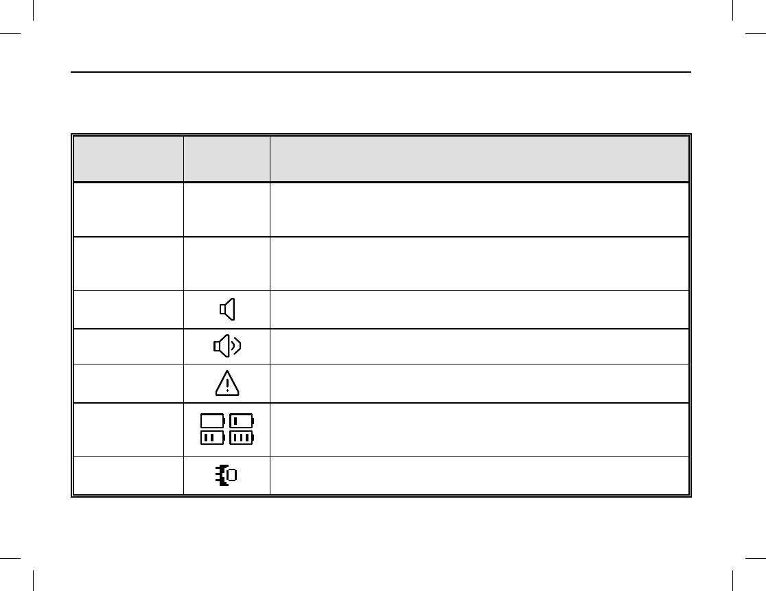
ICON NAME ICON DESCRIPTION
Direct Mode
DM
This operational mode icon indicates the radio is operating in direct
mode. In this mode, radios communicate with each other directly.
This mode is also referred to as “talk around.”
Repeater Mode
RM
This operational mode icon indicates the radio is operating in
repeater mode. In this mode, radios communicate with each other
via a repeater (i.e., radio base station equipment).
Monitor Icon The monitor feature is active. See page 26 for additional
information.
Speaker Icon
The speaker is unmuted.
Emergency Icon
The Emergency mode (other than secret emergency) is active or an
emergency message has been received.
Battery
Strength Icons
These icons indicate the relative strength of the battery. An icon
with more bars indicates more remaining battery operating time. No
bars and beeps indicates the battery needs charging immediately.
Accessory Icon This icon appears in the display when an accessory is connected to
the radio’s accessory connector.
RADIO STATUS INDICATORS
Publication 14222-1150-2000, Rev. A 15
ICON NAME ICON DESCRIPTION
RSSI
Icons
This RSSI icon indicates no radio signal is being received. RSSI
icons appear in the upper left corner of the display. RSSI stands for
Received-Signal Strength Indication.
More bars on an RSSI icon indicate better signal strength.
Transmit (Tx)
Power Level
Icons
Low transmit power for the selected channel.
High transmit power for the selected channel.
Message Icons
New message/unread message.
InBox is full.
Scan Icons
Scanning.
Scanning is paused on a non-priority channel.
Scanning is paused on the priority 1 channel.
Scanning is paused on the priority 2 channel.
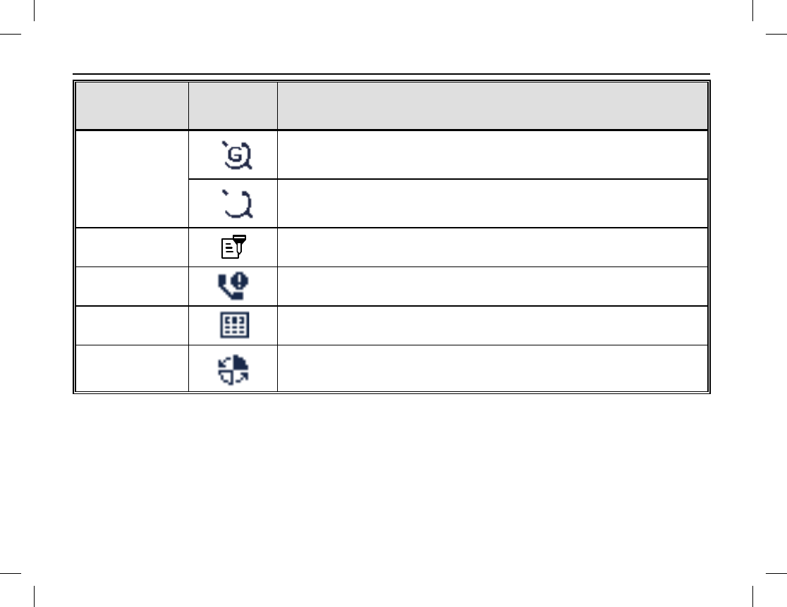
RADIO STATUS INDICATORS
16
ICON NAME ICON DESCRIPTION
GPS Icons
The GPS feature is active and valid GPS data is being received.
The GPS feature is active but no valid GPS data is being received.
Scrambler/-
Encrypt Icon The Scrambler/Encrypt feature is enabled/active.
Missed Call Icon
A call has been missed.
DTMF Keypad
Icon
Dual-Tone Multi-Frequency (DTMF) keypad entry mode is
enabled/on, so numbers can be entered via the radio’s keypad.
Roam Icon
The radio is roaming.
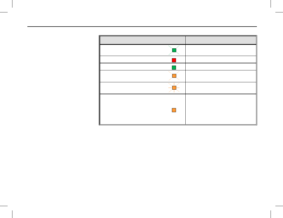
RADIO STATUS INDICATORS
Publication 14222-1150-2000, Rev. A 17
LED INDICATOR
A light-emitting diode (LED)
type status indicator is located
on the top of the radio, near the
On/Off/Volume Control Knob.
This indicator can be quickly
viewed to determine the basic
operational status of the radio.
Each status indication is
described in the table at the
right.
LED INDICATOR RADIO STATUS
Flashing Green
Powering on
Glowing Red
Transmitting
Glowing Green
Receiving
Flashing Orange Slowly
(approximately once every 2 sec.)
Scanning
Flashing Orange Rapidly
(approximately twice every 1 sec.)
Emergency
Glowing Orange
After voice communication
ends, it is OK to transmit voice
audio by
pressing the PTT key
and speaking into the
microphone.
BASIC OPERATIONS
18
TURNING THE RADIO ON AND OFF
To turn on the radio, rotate its On/Off Volume Control knob clockwise out of the detent position. A click
will be sensed. The radio responds by displaying its power-up screen and its LED status indicator flashes green.
This knob is item 13 on page 6.
To turn the radio off, rotate this knob fully counter-clockwise until the detent click is sensed.
ADJUSTING THE VOLUME
After turning the radio on, rotate the On/Off Volume Control knob clockwise to increase the volume and
rotate it counter-clockwise to decrease the volume. Volume adjustment can be made at anytime later in the
same manner. This knob is item 13 on page 6.
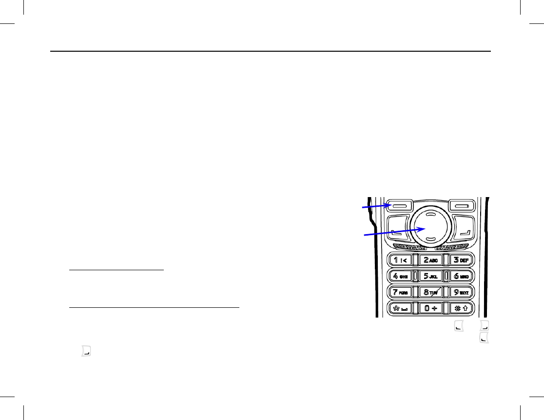
SELECTING A ZONE
A zone is a group of pre-programmed radio channels exhibit-
ing similar properties. The radio supports up to 64 zones and
each zone can have up to 16 channels. Zones and channels
are pre-programmed into the radio by your dealer. Select a
zone using either of the following methods:
• Menu Selection Method — From the home screen, press
the Menu key, select Zone, then use the Up/Down key
to select the desired zone from the menu.
• Pre-Programmed Shortcut Keys Method — If pre-
programmed by your dealer, quickly switch to a desired
zone by pressing the programmed Zone Up or Zone Down shortcut key. Keys SK1, SK2, TK, or
may be pre-programmed by your dealer as Zone Up and Zone Down shortcut keys. The SK1, SK2, TK,
or are illustrated on page 6.
Select/Menu key
Up/Down key

BASIC OPERATIONS
Publication 14222-1150-2000, Rev. A 19
SELECTING A CHANNEL
The radio’s Channel Selector knob is located on the top of the radio. It is item 5 on page 6. Rotate this knob
to select the desired channel within the zone. The name of the selected channel appears in the display.
This knob has 16 positions, for a total of 16 channels per zone. Some knob positions may not be programmed
with a channel.
The number of the newly selected channel will be announced from the radio’s speaker in a synthesized voice if
the radio’s Channel Notify feature is enabled. If desired, enable or disable this feature from the Channel Notify
menu by selecting: Menu > Settings > Radio Set > Tone > Channel Notify > Enable or Disable.
SWITCHING THE CHANNEL MODE BETWEEN ANALOG AND DIGITAL
Each channel can be pre-programmed as either an analog channel or a digital channel. If the currently selected
zone includes both analog and digital channels, the Channel Selector knob can be used to quickly switch
between analog and digital channels. Select the desired channel by rotating the knob to the respective position.
LOCKING AND UNLOCKING THE KEYPAD
The radio’s keypad can be locked to prevent unintentional key activations. Lock and unlock the keypad using
one of the following methods:
• Press the Select/Menu and keys simultaneously. Each press toggles between locked and unlocked.
• If programmed, press the key Keypad Lock shortcut key. Each press toggles between locked and
unlocked. See page 7 for additional information on programmable keys.
• From the Keypad Lock menu select: Setting > Radio Settings > Keypad Lock > Enable or Disable. If
enabled, the keypad will lock automatically within the preset time period if no operation is made. If
disabled, the keypad will not lock automatically. However, it can be manually locked or unlocked via the
Select/Menu and keys, or if pre-programmed, via the Keypad Lock shortcut key.
BASIC OPERATIONS
20
When the Keypad Auto Lock feature is enabled, the keypad will automatically lock if no
operation is made within the pre-programmed time period. The Keypad Auto Lock feature can be
disabled via the Keypad Lock menu.
HOME SCREEN
The home screen is the default operating screen. It indicates the name of the selected zone, the name of the
selected channel, battery strength, and other parameters of the selected channel (via icons) such as if the
channel is a repeater vs. a direct mode channel, the current transmit power level, receive signal strength, etc.
To return to the home screen from any menu screen, simply press the Back key one or more times. Alternately,
if the Home Screen shortcut key is pre-programmed, press it to exit the menu screen and immediately return
to the home screen. In an editing screen, press the Home Screen shortcut key to exit and immediately return
to the previously selected menu.
PRIVATE CALLS
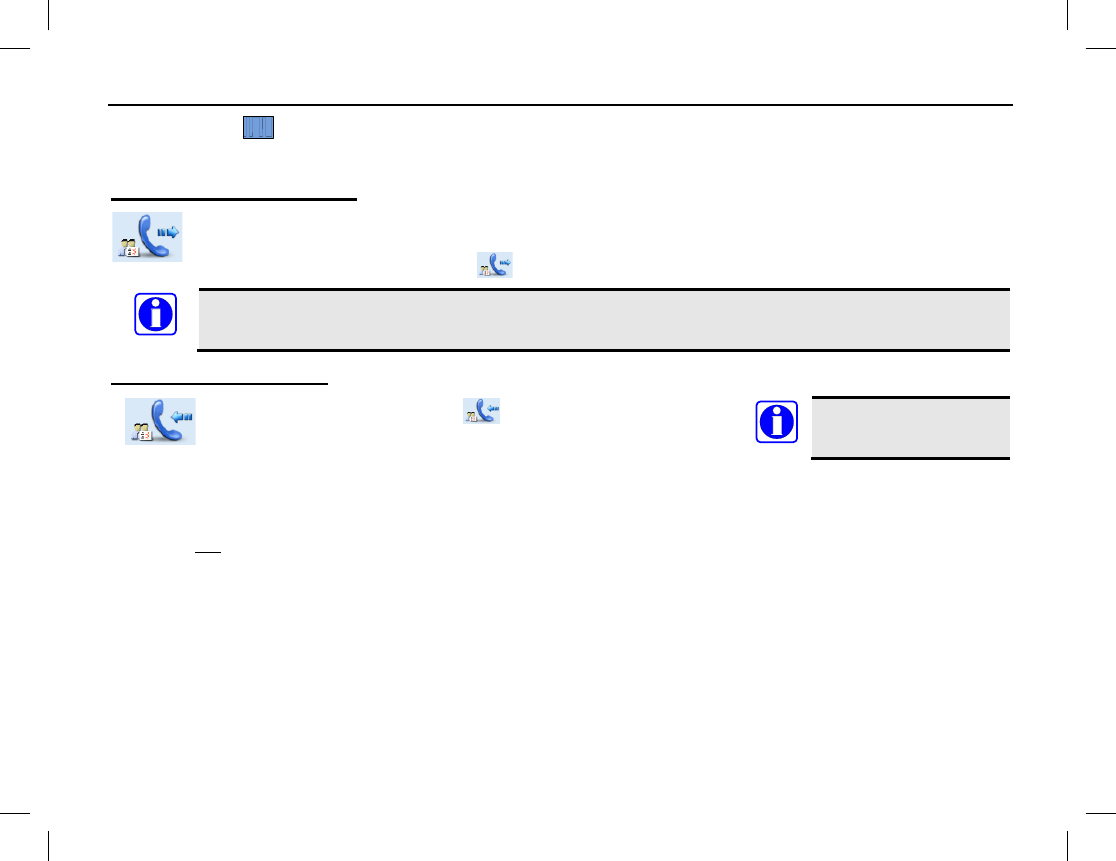
A private call is a call initiated by a radio user to another radio user.
Transmitting a Private Call
When transmitting a private call, the icon appears in the display. A private call can be
transmitted using a method described in the following subsections.
When transmitting (i.e., PTT key depressed), hold the front of the radio between 1 to 2 inches
from your mouth and speak into the microphone at a normal voice level. This will ensure optimal
reception at the receiving radio unit(s). Never shout or whisper when transmitting. As illustrated
on page 6, the radio’s microphone is located just above the display.
NOTE
NOTE

BASIC OPERATIONS
Publication 14222-1150-2000, Rev. A 21
Transmitting a Private Call to the Preset Contact
While in the home screen, hold down the radio’s PTT key to transmit a private call to the Private Call contact
preset for the currently selected channel. Release the PTT key to stop transmitting, and listen for a reply. See
Receiving and Responding to a Private Call for additional information.
Each digital channel may be pre-programmed with a preset contact by your dealer. The preset
contact can be a Private Call contact, a Group Call contact, or an All Call contact.
Transmitting a Private Call via the Contact List or Call Logs
1. While in the home screen, press the Menu key.
2. Select Contact > Contact List. Alternately, go to Call Logs and access the Outgoing/Incoming/Missed
list.
3. Press the Up/Down key to select the Private Call contact desired for calling. In this list, each Private Call
contact name is preceded by a icon.
4. Hold down the PTT key to transmit a private call to the selected contact, and speak into the microphone at
a normal voice level.
5. Release the PTT key to stop transmitting, and listen for a reply. See Receiving and Responding to a Private
Call for additional information.
Transmitting a Private Call via Manual Input
1. While in the home screen, press the Menu key.
2. Select Contact > Manual Dial.
3. Enter the Private Call contact desired for calling.
4. Hold down the PTT key to transmit the private call, and speak into the microphone at a normal voice level.
5. Release the PTT key to stop transmitting, and listen for a reply.
NOTE
BASIC OPERATIONS
22
If the radio is programmed for Private Call Manual Dial and Group Call Manual Dial, switch
between these by pressing the
key. The appropriate ID is displayed.
If the radio is programmed with the Default Numeric Key Selection enabled, you can enter a
Private Call number in the home screen using the keypad, and then hold down the PTT key to
transmit the Private Call. However, if the DTMF keypad is enabled, the number entered in the
home screen is a phone number. You can dial the Private Call number through the Manual Dial
menu only.
Receiving and Responding to a Private Call
When a private call is received, the icon appears in the radio’s display.
To respond to the call,
hold down the PTT key within the preset time period
, and speak into the microphone at a normal
voice level.
If you do not respond to a received private call, the
missed call icon appears at the top of the
display. In addition, if the radio is programmed with Display Missed Call enabled, the large
icon also displays.
NOTE
NOTE
BASIC OPERATIONS
Publication 14222-1150-2000, Rev. A 23
GROUP CALLS
A group call is a call initiated by a radio user to a group of radio users.
Transmitting a Group Call
When transmitting a group call, the icon appears in the display. A group call can be
transmitted using either method described in the following subsections.
When transmitting (i.e., PTT
key depressed), hold the front of the radio between 1 to 2 inches
from your mouth and speak into the microphone at a normal voice level. This will ensure optimal
reception at the receiving radio unit(s). Never shout or whisper when transmitting. As illustrated
on page 6, the radio’s microphone is located just above the display.
Transmitting a Group Call to the Preset Contact
While in the home screen, hold down the radio’s PTT key to transmit a group call to the Group Call contact
preset for the currently selected channel. Release the PTT key to stop transmitting, and listen for a reply. See
Receiving and Responding to a Group Call for additional information.
Each digital channel may be pre-programmed with a preset contact by your dealer. The preset
contact can be a Private Call contact, a Group Call contact, or an All Call contact.
Transmitting a Group Call via the Contact List
1. While in the home screen, press the Menu key.
2. Select Contact > Contact List.
3. Press the Up/Down key to select the Group Call contact desired for calling. In this list, each Group Call
contact name is preceded by a icon.
NOTE
NOTE
BASIC OPERATIONS
24
4. Hold down the PTT key to transmit a group call to the selected contact, and speak into the microphone at a
normal voice level.
5. Release the PTT key to stop transmitting, and listen for a reply.
Transmitting a Group Call via Manual Input
1. While in the home screen, press the Menu key.
2. Select Contact > Manual Dial.
3. Enter the Group Call contact desired for calling via the keypad.
4. Hold down the PTT key to transmit the group call, and speak into the microphone at a normal voice level.
5. Release the PTT key to stop transmitting, and listen for a reply
If the radio is programmed for Private Call Manual Dial and Group Call Manual Dial, switch
between these by pressing the key. The appropriate ID is displayed.
If the radio is programmed with the Default Numeric Key Selection enabled, you can enter a
Group Call number in the home screen using the keypad, and then hold down the PTT key to
transmit the Group Call. However, if the DTMF keypad is enabled, the number entered in the
home screen is a phone number. You can dial the Group Call number through the Manual Dial
menu only.
Receiving and Responding to a Group Call
When a group call is received, the icon appears in the radio’s display.
To respond to the call,
hold down the PTT key within the preset time period
, and speak into the microphone at a normal
voice level.
NOTE
NOTE
BASIC OPERATIONS
Publication 14222-1150-2000, Rev. A 25
ALL CALLS
An all call is a call initiated by a radio user to all radio users on the channel.
Transmitting an All Call
All calls can be transmitted to the preset contact or to a contact on the Contact list. Methods for
transmitting an all call are the same as those described for Transmitting a Group Call on page 23.
When transmitting an all call, the icon appears in the display.
All calls can only be transmitted if enabled by your dealer via radio pre-programming.
Receiving an All Call
When an all call is received, the icon appears in the display.
It is not possible to
respond to an all call.
TALK-AROUND (DIRECT MODE)
The talk-around feature provides direct radio-to-radio communications. With talk-around, a radio repeater
system is not required for radio communications. This type of operation is sometimes called “direct mode.”
Talk-around is beneficial when, for example, a radio repeater system malfunction has occurred, or when the
radio is out-of-range of a radio repeater system, but other radios are nearby that can communicate on the same
pre-programmed radio channels.
To toggle radio operation between normal communications mode (repeater mode) and talk-around, press the
pre-configured Talk-Around shortcut key. When in talk-around/direct mode, the
DM
icon appears near the
upper left corner of the display. When in repeater mode, the
RM
icon appears.
NOTE
NOTE

BASIC OPERATIONS
26
CALLS ON ANALOG CHANNELS
Transmitting a Call on an Analog Channel
1. If not already, select the desired analog channel.
2. Listen for a clear channel. In other words, if another person is using the channel, wait for them to finish
transmitting/speaking. If pre-programmed, a monitor or squelch off shortcut key should be used to verify
the channel is clear. See the following sections for additional information on these functions.
3. Hold down the radio’s PTT key and speak into the microphone at a normal voice level.
4. Release the PTT key to stop transmitting and listen for a reply.
Receiving a Call on an Analog Channel
1. If not already, select the desired analog channel. Do not press the PTT key.
2. When an incoming call is received on the channel, rotate the On/Off Volume Control knob as necessary
to adjust the volume.
If pre-programmed, a monitor or squelch off shortcut key can be used to verify there is no signal on the
channel. Also, the Squelch Off shortcut key can be used in weak signal conditions.
Monitor
Monitor is a function for analog channels that allows any pre-
programmed receiver decoding to be
disabled so calls (or other activity) on the selected channel without the correct code can be monitored.
This does not disable receiver squelch. When the Monitor function is enabled, the icon appears in the top of
the display, and any calls on the channel will be heard in the radio’s speaker.
To enable and disable the Monitor function, press the pre-programmed Monitor shortcut key, or the Monitor
Momentary shortcut key. The Monitor shortcut key provides a toggle on/off type function, whereas the
Monitor Momentary shortcut key temporarily enables the function only when the shortcut key is depressed.

BASIC OPERATIONS
Publication 14222-1150-2000, Rev. A 27
Squelch Off
Squelch Off is an analog channel function that, when enabled, keeps the receiver unsquelched
(i.e., not
muted) even when there is no signal on the selected channel. When enabled, the
icon appears in
the top of the display and call audio on the channel (or receiver noise) is routed to the radio’s speaker.
To toggle squelch between enabled and disabled, press the pre-configured Squelch Off shortcut key.
To momentarily turn squelch off, depress the pre-configured Squelch Off Momentary key. When this key is
released, squelch turns back on.
Telephone Interconnect Calls
If an analog channel’s repeater site equipment is connected to a Public Switched Telephone Network (PSTN)
gateway system, the radio can make a phone call through this channel and phone system.
Transmitting a Phone Call
1. Select an analog channel that has a PSTN connection. Consult with your radio dealer as necessary.
2. Access the phone system using either a Live Dial method or Buffer Dial method as follows:
• Live Dial — Hold down the PTT key, then enter the access code via the radio’s keypad and release the
PTT key. The radio beeps and displays the dialing information. When the phone system is accessed
successfully, the radio automatically goes to the DTMF keypad mode.
• Buffer Dial — Access the phone system as follows:
A. Enter the DTMF keypad mode using one of the following methods:
• From the home screen, press the Menu key then select Phone > Manual Dial to enter the
DTMF keypad mode.
• Press the programmed DTMF Keypad shortcut key.
• From the home screen, press the Menu key then select Phone > DTMF Keypad > Enable.

BASIC OPERATIONS
28
B. Enter the phone system’s access code via the radio’s keypad and then press the PTT key. The
radio beeps and displays the dialing information. When the phone system is accessed successfully,
the radio goes to the DTMF keypad mode again.
3. Dial the desired phone number using one of the following methods:
• Live Dial — Hold down the PTT key and enter the phone number via the radio’s keypad. Release the
PTT key after the complete phone number has been entered.
• Buffer Dial — Enter the phone number via the radio’s keypad and then hold down the PTT key.
• Select the Back and then the Menu keys, and then select Phone > Phone List to select a desired
contact. Next, press the PTT key.
4. After the call is established, hold down the PTT key to talk, and release it to listen. To end the call, send
the de-access code to exit the phone system; the input method is the same as that for the access code.
If the phone is hung up, the call will end and the phone system will exit.
Receiving a Phone Call
When the radio receives a phone call, the icon or the icon displays.
To respond
to the call, hold down the PTT key within the preset time period
, and speak into the
microphone at a normal voice level.
If you do not respond, the radio will provide appropriate indications. If you do not respond to a received phone
call, the missed call icon appears at the top of the display. In addition, if the radio is programmed with
Display Missed Call enabled, the large icon also displays.
BASIC OPERATIONS
Publication 14222-1150-2000, Rev. A 29
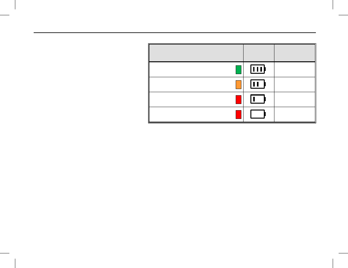
BATTERY STRENGTH INDICATOR
If the Battery Strength Indicator
shortcut key is pre-programmed, this
function can be used to quickly check the
remaining battery strength via the LED
indicator on the top of the radio. This may
be beneficial during certain ambient light
conditions, or when the respective icons in
the radio’s display cannot be easily
viewed. Simply press and hold this pre-
programmed shortcut key and view the
LED indicator on the top of the radio.
LED INDICATOR DISPLAY
ICON BATTERY
STRENGTH
Glowing Green
High
Glowing Orange
Medium
Glowing Red
Low
Glowing Red
(and Low Battery Alert Tone Sounds)
Insufficient
MENU NAVIGATION
30
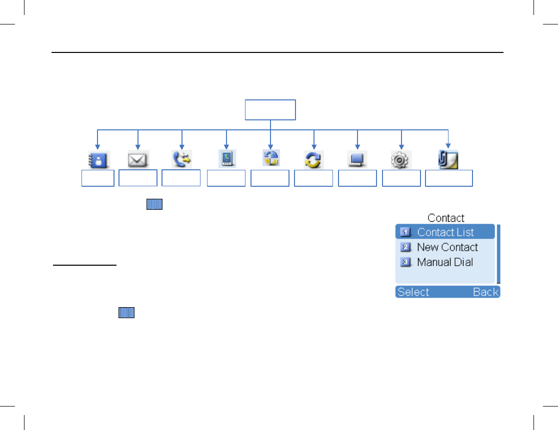
MAIN MENU
The radio’s main menu structure is shown in the following diagram. To access the main menu, press the Menu
key on the home screen. Each menu is described in the subsections that follow.
Main Menu
Contact Message Call Logs Scan Zone Settings Accessories
Roaming
Phone
CONTACT MENU
To access the Contact menu, first select a digital channel (if not already), then
press the Menu key in the home screen and select Contact. The Contact menu
displays:
Contact List
Up to 512 entries can be saved in the Contact List. To access this list, select
Contact List in the Contact menu, or if programmed, press Contact List
shortcut key while on a digital channel. List functions include:
Ctrl Services — Use this to send a Private Call contact one of the following commands: alert call, radio
check, remote monitor, radio enable, or radio disable. See Manual Dial on page 31 for details.
Editing a Contact — Use this to edit the number and alias of each private call contact.
Viewing a Contact — Use this to view details about each contact.
MENU NAVIGATION
Publication 14222-1150-2000, Rev. A 31
Deleting a Contact — Use this to delete a private call contact. However, when there is only one entry left in
the list, it cannot be deleted. In addition, the private call contact preset on the currently used channel cannot be
deleted.
New Contact
To add a private call contact to the Contact list, select New Contact in the Contact menu. The number and
alias of each contact must be unique, and the available number range is 1 to 16776415.
Manual Dial
To manually input a number for calling, select Manual Dial in the Contact menu. Any of the following
commands can then be performed:
On a digital channel, if the radio is programmed for Private Call Manual Dial and Group Call
Manual Dial, switch between these by pressing the key. The appropriate ID is displayed.
Alert Call — Use the Alert Call command to send an alert call to a Private Call contact. The called party
will see the alert and can then call you back.
Radio Check — The Radio Check command is used to check a remote radio on the Private Call contact
list, while not disturbing the contact/radio operator. This command can be used to confirm whether the called
radio is powered on and on your selected channel.
Remote Monitor — Use this Remote Monitor command to enable the microphone of a remote Private
Call contact’s radio. This can be used to remotely monitor voices and background sounds near the contact
radio’s microphone.
Radio Enable — Use this Radio Enable command to enable the radio of a remote Private Call contact for
normal use.
Radio Disable — Use this Radio Disable command to disable the radio of a remote Private Call contact
from normal use.
NOTE
MENU NAVIGATION
32
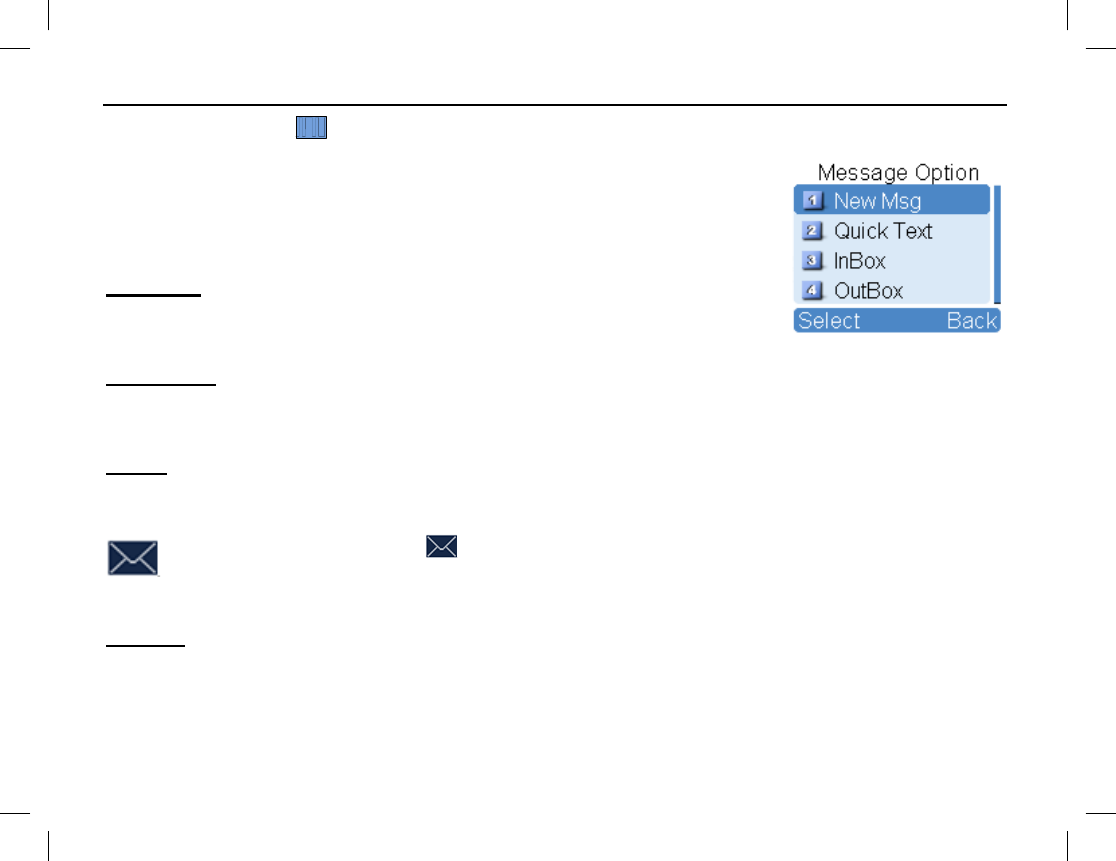
MESSAGE MENU
To access the Message menu, first select a digital channel (if not already), then
press the Menu key in the home screen and select Message. Alternately, access
this menu by pressing the respective pre-programmed shortcut key while on a
digital channel. The Message menu displays. This menu supports the text
messaging feature of the radio:
New Msg
Select New Msg to create a new text message and send it to an individual (via
private call) or to a talk group. Text message length is limited to 256 characters.
Quick Text
Under Quick Text, there are up to 25 pre-programmed text messages. You can edit and send any one of these
messages.
InBox
Select InBox to access the InBox. The InBox can save up to 20 received text messages. For each text message,
any of the following operations can be performed: Reply, Forward, View Details, and Delete.
When the InBox is full, the icon will appear, and the earliest message will be automatically
overwritten by the last message that was received.
To delete all messages in the InBox, select Message > InBox > Delete All.
OutBox
Select OutBox in the Message menu to access the OutBox. The Outbox can save up to 20 sent messages.
When the OutBox is full, the earliest message will be automatically overwritten by the last one that was sent.
MENU NAVIGATION
Publication 14222-1150-2000, Rev. A 33
For each message, you can choose to perform any of these operations: Resend, Forward, View Details, and
Delete.
To delete all messages in the OutBox, press the Menu key in the home screen and select Message > OutBox
> Delete All.
Drafts
Drafts can save up to 20 draft messages. When full, the earliest message will be automatically overwritten by
the last one entered.
For each draft message, you can choose to perform any of these operations: Send, Save, and Delete.
To delete all draft messages, select Message > Drafts > Delete All.
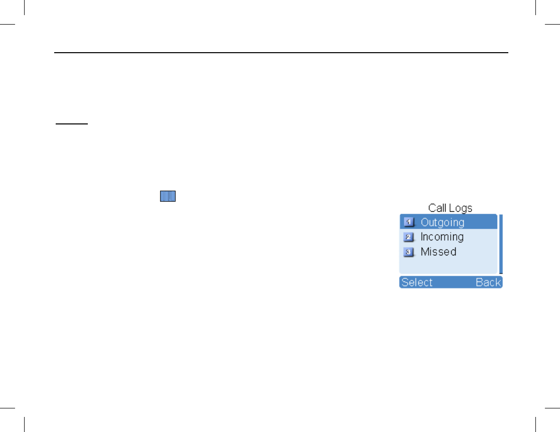
CALL LOGS MENU
To access the Call Logs menu, first select a digital channel (if not already), then
press the Menu key in the home screen and select Call Logs. Alternately, access
this menu by pressing the respective pre-programmed shortcut key while on a
digital channel.
Selections on this menu include Outgoing, Incoming, and Missed, for outgoing,
incoming, and missed calls respectively. Up to ten (10) private call entries can be
saved in each log. When a log is full, the oldest entry will be automatically
overwritten by latest one.
After accessing a log and selecting an entry, any one of the following actions can be performed: Hold down the
PTT key to initiate a call to the selected entry, add the selected entry to Contact List, or delete the entry.
To delete all entries in a particular log at the same a time, select Call Logs > Outgoing/Incoming/Missed
> Delete All.

MENU NAVIGATION
34
PHONE MENU
This menu supports telephone calls, as described in the section beginning on page 27. To access the Phone
menu (if programmed), press the Menu key in the home screen and select Phone.
Phone List
Select Phone List to view and use stored phone numbers. Alternately, if programmed by your radio dealer,
press the programmed Phone List shortcut key to quickly access this list.
Manual Dial
Using the (optional) keypad microphone, select Manual Dial to manually enter a phone number for calling.
See page 27 for additional information.
DTMF Keypad
Select DTMF Keypad to manually enter a phone number for calling via the (optional) keypad microphone.
The entered number appears in the home screen. This is the DTMF code that will be transmitted when the
radio’s PTT key is pressed. See page 27 for additional information.
ROAMING MENU
Use this menu to enable and disable the roam feature. Access this menu (if programmed) by pressing the Menu
key in the home screen and then selecting Roaming.
MENU NAVIGATION
Publication 14222-1150-2000, Rev. A 35
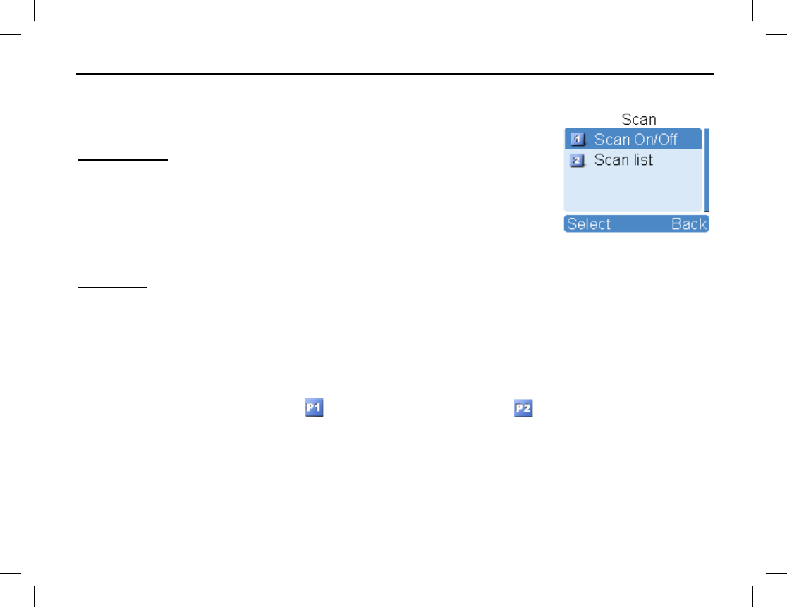
SCAN MENU
To access the Scan menu, press the Menu key in the home screen and then select
Scan:
Scan On/Off
The Scan feature allows you to listen to communication activities on other
channels. Select Scan On/Off on this menu to toggle scan operation on and off.
When scan is off, the radio does not scan channels on the list; it simply remains on
the selected channel. When scan is on, the radio scans channels according to the
scan list set for the channel on which scanning starts. Refer to page 42 for
additional information on channel scanning.
Scan List
Scan lists can be pre-programmed into the radio by your dealer for each channel, and then edited when desired
as described below. Each scan list may contain 32 digital or analog channels. Each scan list can be edited via
menu selection as follows:
Adding a Channel — Use this function to add a new channel to the active scan lists.
Editing Priority Channel — Use this function to set the selected channel as a non-priority channel or as a
priority channel. A priority channel will scanned more frequently than non-priority channels. Each scan list may
contain up to two (2) priority channels. indicates priority channel 1, and indicates priority channel 2.
Deleting a Channel — Use this function to remove a channel from the active scan list. However, the first
channel in the list cannot be deleted.
MENU NAVIGATION
36
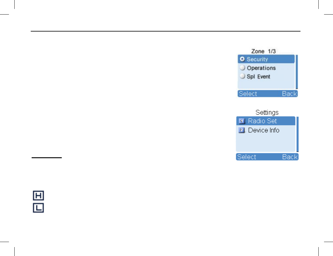
ZONE MENU
The radio supports up to 64 zones. Each zone is pre-programmed into the radio. To
access the Zone menu, press the Menu key in the home screen, select Zone, and
then use the Up/Down keys to select the desired zone from the menu.
SETTINGS MENU
Using the Settings menu, radio settings can be customized by changing various
parameters according to actual user/operator needs and preferences. Also, this
menu can be used to display basic device information about the radio. To access
the Settings menu, press the Menu key in the home screen and then select
Settings:
Radio Set
Selections within Radio Set include:
Power Level — Use this to change between the low and high transmit (TX) power levels. Alternatively, the
power level can be changed by, while in the home screen, pressing the pre-programmed Adjust Power Level
shortcut key. Two (2) power levels are available:
High Transmit Power Level —
Use this level whenever an increased communications range is necessary.
Low Transmit Power — To avoid unnecessary communications interference, use
this level whenever
possible. Use of this level can also increase battery operating time.
MENU NAVIGATION
Publication 14222-1150-2000, Rev. A 37
The power level should be individually set for each channel.
Squelch — Select this to set an appropriate receiver squelch level via the Adjust Squelch Level sub-
menu. Alternatively, press the assigned shortcut key to access the Adjust Squelch Level sub-menu. There are
three (3) levels available: Tight, Normal, and Open. The default squelch level is Normal. It is often used in a
low radio frequency noise environment. Generally, the Tight level should be used in a high radio frequency
noise environment; it requires a stronger received radio signal to unmute the receiver. Using Open will keep the
speaker unmuted, regardless of the noise level or the decode settings.
Scramble — Use this to enable/disable the scrambler feature. This feature employs analog voice
inversion technology.
Encrypt — Use this to enable/disable the encrypt feature and to set parameters of this feature, as follows:
• On/Off — Enable (turn on) or disable (turn off) encryption.
• Key List — Select one of 30 possible encryption keys.
• New Key — Use this to create a new key ID, which consists of numbers only (range =1 to 255).
• Key Alias — Use this to create a key alias (up to 16 characters) for a key. The key alias cannot be the
same as the key ID.
• Key Length — Use this to edit the length of a new key.
• Key Value — Use this to edit a key’s value. Values can consist of numbers and the letters A through F
(within the predefined key length).
• Save — Use this to save a key and add it to the key list.
If a key must be deleted, consult with your radio dealer for assistance.
NOTE
NOTE

MENU NAVIGATION
38
Language — Use this to set the language of the radio’s menus.
Backlight — Use this to set backlight to either on, off, or timer. When set to timer, the backlight turns off a
pre-programmed time period after user key presses end. The timer is pre-programmable by your dealer with a
time period of between 5 and 60 seconds.
Brightness — Use this to set display brightness. Raise or lower it using the Up/Down key.
Keypad Lock — Use to set whether to enable this function. When enabled, the Up/Down key can be used to
set the time range after which the keypad will be locked. Available range is between 5 and 60 seconds. If
enabled, the keypad will lock automatically within the preset time period if no operation is made. If disabled,
the keypad will not lock automatically. See page 19 for additional information.
LED — Use this to enable and disable the LED indicator located on the top of the radio. When disabled, the
LED indicator always remains off (i.e., it does not light up). See page 17 for additional information.
Tone — Use this to configure radio alert tones. The following settings are available:
Radio Silent: Use this to enable and disable all tones. If Silent On is selected, all tones remain silent.
Keypad: Use this to set whether the radio will sound a tone for keypad operations.
TextMsg: Use this to set whether the radio will sound a tone when it receives a message.
Private Call: Use this to set whether the radio will sound a tone when it receives a private call.
Group Call: Use this to set whether the radio will sound a tone when it receives a group call.
Talk Permit: Configures the transmit (Tx) talk permit tone. The following selections are available:
Disable (no tone sounded at Tx), Digital Only (tone sounded at Tx on digital channels only), Analog Only
(tone sounded at Tx on analog channels only), and Enable (tone sounded at Tx on both analog and digital
channels).
Call End: Use to set whether or not a tone is generated when a call ends.
Voice End: Use to set whether or not a tone is generated after a voice call ends.

MENU NAVIGATION
Publication 14222-1150-2000, Rev. A 39
Low Battery: Use to set whether or not a tone is generated when the radio’s battery needs charging.
Channel Notify: Use to set whether or not the number of the newly selected channel will be announced
from the radio’s speaker in a synthesized voice. See page 19 for additional information.
Signaling Side: Use to set whether or not the radio will sound continuous tone during a signaling
transmission. This feature is available for calls for HDC1200/5-tone/2-tone systems.
Vibration — Use this to enable and disable radio vibration. If enabled, the radio will vibrate when it receives a
text message or a private call.
Lone Worker — Use this to enable and disable the radio’s Lone Worker feature. See page 50 for additional
information about this feature.
Man Down (Optional) — Use this to enable and disable the radio’s man down feature. See page 52 for
information about this feature.
Device Info
Select Device Info on the Setting menu to view basic information about the radio, including serial number,
model number, frequency range, firmware version, etc.
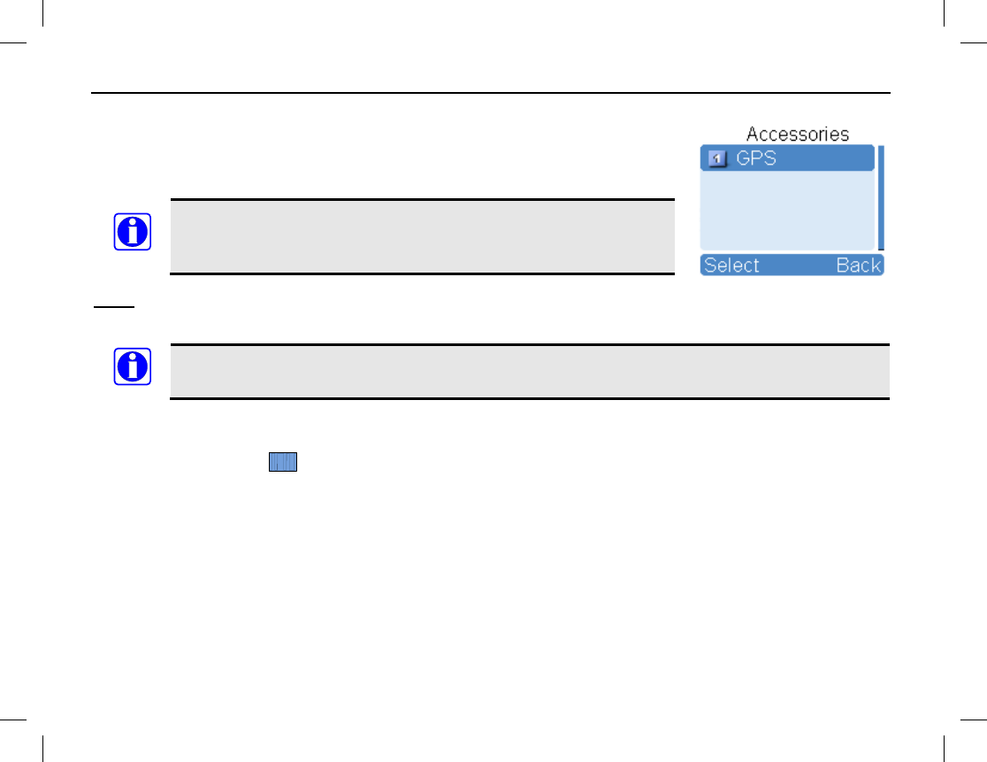
MENU NAVIGATION
40
ACCESSORIES MENU
Use the Accessories menu to view, change, and send Global Positioning System
(GPS) related information and/or other accessories functions. To access this menu,
press the Menu key in the home screen and then select Accessories.
The Accessories menu only appears if the radio is equipped with an
internal GPS receiver or if it is pre-
programmed with another
accessory function.
GPS
GPS Switch — Use this to enable or disable the radio’s GPS feature.
Enabling the GPS feature will shorten the operating time of the battery.
Position — This selection displays longitude, latitude, time, date, speed (displayed in nautical miles-per-
hour), altitude, and GPS satellite (SA) information based upon signals received by the radio’s GPS receiver.
GPS Text Message — On a digital channel, send the radio’s GPS position via a text message as
follows:
1. Press the OK key. The Contact List is selected by default.
2. Press the OK key again to access the contact list then press the Up/Down key to select the contact which
the GPS text message should be transmitted to.
Alternately, select a contact via Manual Dial on the Contact menu, and enter the private call or group call
number using the keypad on the (optional) keypad microphone. See Manual Dial on page 31 for additional
information.
3. Press the OK key to transmit/send the GPS location information message to the selected contact.
NOTE
NOTE

MENU NAVIGATION
Publication 14222-1150-2000, Rev. A 41
Time Zone — This function allows setting of the local time zone, so the received GPS time (hours) is
correctly displayed. The zone should be correctly set to before the initial use of this feature. For example, if the
time at your location is 5.45 hours earlier than GMT, select “GMT+5.45” as your time zone.

SCANNING CHANNELS
42
GENERAL INFORMATION
The radio’s scan feature allows scanning of radio channels pre-programmed into the radio for call activity. Scan
lists can be pre-programmed for each channel and then edited as desired. Each scan list may contain 32 digital
or analog channels. When the radio is scanning channels:
• The icon appears in the top of the display.
• The LED indicator on the top of the radio flashes orange slowly.
• The radio scans the channels currently on the scan list for calls (or other activity).
• When a call (or other activity) is received/detected on a channel in the scan list:
o The call’s audio is routed to the radio’s speaker.
o The radio remains on the channel (i.e., scan operation automatically pauses) until the call (or other
activity) ends.
o The icon displays while the radio is paused on a non-priority scan channel.
o The icon displays when the radio is paused on the priority 2 scan channel. During this time,
scanning pauses until the call ends.
o The icon displays when the radio is paused on the priority 1 scan channel. During this time,
scanning pauses until the call on the priority 1 scan channel ends.
OPERATION
Turning Scan On and Off
Scan can be turned on and off via the Scan menu or, if pre-programmed, by pressing the Scan shortcut key.
Both are toggle-type functions. For details on using the Scan menu, see page 35.

SCANNING CHANNELS
Publication 14222-1150-2000, Rev. A 43
The radio can be pre-programmed with the Auto Scan feature on a per-channel basis. If so, the radio will
automatically begin scanning the channel’s scan list when the channel is selected. In this case, to turn scan off,
use the Scan menu or, if pre-programmed, press the Scan shortcut key once.
Pausing Scan
If a call is received on an analog channel and staying on the channel (i.e., pausing scan) is desired so additional
transmissions can be heard on it, press the pre-programmed Monitor or Squelch Off shortcut key when a call
is on the channel. When the Monitor function is on, the icon appears in the top of the display and if present,
call audio on the channel is heard in the radio’s speaker. When the Squelch Off function is on or when a call is
on the channel, the icon appears in the top of the display and call audio on the channel (or receiver noise) is
heard in the radio’s speaker. Press the shortcut key again or the Scan shortcut key to unpause scan.
Nuisance Temporary Delete
To temporarily remove a channel from a channel’s scan list so calls on it will not pause scanning, press the pre-
programmed Nuisance Temporary Delete shortcut key when a call is on the channel. In this case, the
channel will not be scanned again until after a menu action is completed, the channel or zone is changed, the
radio is power-cycled, or scan is turned off and back on. See page 35 for details on editing a scan list.
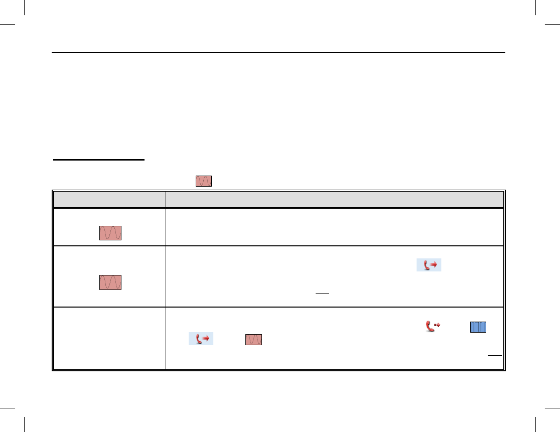
EMERGENCY COMMUNICATIONS
44
GENERAL INFORMATION
The radio’s emergency feature can be used to summon help from another radio operator(s) and/or via a radio
dispatch/control center. The emergency process has the highest call priority throughout the radio communica-
tions system. Emergency operations can be performed when the radio is transmitting or receiving. The radio
can be pre-programmed with different emergency modes, emergency types, and emergency ID types. These are
described in the following subsections. Each channel can be pre-programmed with different emergency system
operation. Consult your radio dealer for specific information on how your radio is pre-programmed:
Emergency Mode
The radio supports three (3) emergency modes, as defined in the following table. Two (2) of the three modes
apply only to analog channels (see symbol). To select a different mode, consult with your radio dealer:
EMERGENCY MODE DESCRIPTION
Alarm
With this mode, you can send alarm information to
another radio operator
or to a dispatch/control center, but you cannot transmit voice audio. Initiate
by pressing the pre-programmed Emergency shortcut key.
Alarm with Call
With this mode, you can send alarm information by pressing the pre-
programmed Emergency shortcut key. Next, when the icon appears
in the display, simply speak into the microphone to transmit your
voice.
Pressing the radio’s PTT key is not necessary when speaking in the mic.
This is commonly referred to as a “hot-mic” condition.
Call Only
With this mode, you can send alarm information by pressing the pre-
programmed Emergency shortcut key. Next, when the icon ( )
or
the icon ( ) icon appears in the display, simply
speak into the
microphone to transmit your voice. Pressing the radio’s PTT key is not
necessary when speaking in the mic (i.e., a hot-mic condition).
EMERGENCY COMMUNICATIONS
Publication 14222-1150-2000, Rev. A 45
Emergency Type
The radio supports four (4) emergency types, as defined in the following table. To select a different type,
consult with your radio dealer:
EMERGENCY TYPE DESCRIPTION
Siren Only
When an emergency occurs, the radio sounds a shrill alarm tone and
displays the icon.
Regular
When an emergency occurs, the radio gives an audible and a visual
indication.
Silent
When an emergency occurs, the radio does not give any indication,
audible or visual. This type is typically employed in covert operations.
Silent with Voice
When an emergency occurs, the radio does not give any audible or visual
indication, but it will receive voice audio response(s) from other radios or a
dispatch/control center transmitting on the emergency channel.
This type
is typically employed in covert operations.
Emergency ID Type
The radio supports two (2) emergency ID types on analog channels, as defined in the following table. To select
a different ID type, consult with your radio dealer:
EMERGENCY TYPE DESCRIPTION
None No signaling is used when the radio transmits alarm information.
HDC1200 HDC1200 signaling is used when the radio transmits alarm information.
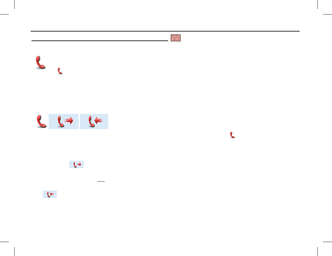
EMERGENCY COMMUNICATIONS
46
Emergency Operations on Analog Channels
Alarm Emergency Mode
If the radio is pre-programmed for Alarm emergency mode operations on the selected analog channel,
press the pre-programmed Emergency shortcut key transmit an alarm. When an alarm is transmitted,
a (red phone handset) icon and “Sending Alarm” is displayed. Also, the LED indicator on the top
of the radio rapidly flashes orange then glows red to indicate the alarm transmission. The radio may also be pre-
programmed to sound an audible alarm.
The alarm will be transmitted until the pre-programmed number of alarm cycles completes, or it can be ended
early by long-pressing the pre-programmed Emergency shortcut key.
Alarm with Call Emergency Mode
If the radio is pre-programmed for Alarm with Call
emergency mode
operations on the selected analog channel, use this feature as follows:
1. Press the pre-programmed Emergency shortcut key. The radio displays a (red phone handset) icon
and “Sending Alarm” in its display. Also, the LED indicator on the top of the radio rapidly flashes orange
then glows red to indicate the alarm transmission. The radio may also be pre-programmed to sound an
audible alarm.
2. When the icon appears in the display, the radio is in a hot-mic condition for a pre-programmed
period of time. Speak in to the microphone to transmit voice audio on the selected analog channel. Pressing
the radio’s PTT key is not necessary during this time. The LED indicator glows red during this time.
3. After the pre-programmed hot-mic time ends, the radio then enters a receive period, as indicated by the
icon in the display. Listen for a reply during this period of time.
4. If the radio is pre-programmed with more than one voice cycle, it will repeat the transmit (with hot-mic)
and receive periods for the number of pre-programmed cycles.

EMERGENCY COMMUNICATIONS
Publication 14222-1150-2000, Rev. A 47
5. After the voice cycle(s) expires, additional voice calls can be made by pressing the radio’s PTT key. The
icon appears in the display and the LED indicator glows red. Release the PTT key to end the voice
call (transmission) on the emergency channel. The radio displays the icon and the LED indicator
flashes orange rapidly. If an HDC1200-format signaling call is received, the icon appears in the
display.
The Alarm with Call emergency mode transmission will continue until the pre-programmed number of alarm
cycles and voice cycles completes. Alternately, it can be ended early by long-pressing the pre-programmed
Emergency shortcut key.
Call Only Emergency Mode (HDC1200 Signaling Only)
If the radio is pre-programmed for Call Only
emergency mode operations on
the selected analog channel, use this feature as follows:
1. Press the pre-programmed Emergency shortcut key. The radio displays a (red phone handset) icon
and switches to the dedicated/revert channel for the emergency call. Also, the LED indicator on the top of
the radio rapidly flashes orange then glows red to indicate the alarm transmission. The radio may also be
pre-programmed to sound an audible alarm.
2. If the feature “Alarm with Call to Follow” is enabled, voice audio can be transmitted by speaking into the
microphone when the icon appears in the display.
The radio displays the icon when it is ready to receive.
When a call is received, the icon appears in the display.
3. After the voice cycle(s) expires, additional voice calls can be made by pressing the radio’s PTT key. The
icon appears in the display and the LED indicator glows red. Release the PTT key to end the voice
call (transmission) on the emergency channel. The radio displays the icon and the LED indicator
flashes orange rapidly. If a call is received, the icon appears in the display.
To exit the emergency mode early, long-press the pre-programmed Emergency shortcut key.
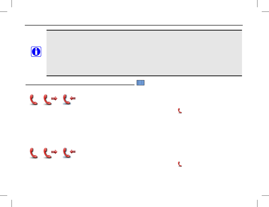
EMERGENCY COMMUNICATIONS
48
The following parameters are pre-programmed by your radio dealer:
• Number of voice cycles;
• Duration of each transmission;
• Transmission interval;
• If without HDC1200 signaling:
• Number of alarm cycles; and,
• Alarm duration.
• If with HDC1200 signaling:
• Number of polite retries; and
•
Number of impolite retries.
Emergency Operations on Digital Channels
Alarm Emergency Mode
If the radio is programmed for Alarm (only)
emergency mode operations on the
selected digital channel, use this mode as follows:
1. Press the programmed Emergency shortcut key. The radio displays a (red phone handset) icon and
“Sending Alarm” is displayed as the alarm is transmitted. Also, the LED indicator glows red to indicate
the alarm transmission.
2. Once the emergency cycles expire, the radio exits the emergency mode automatically.
To exit the emergency mode early, simply long-press the programmed Emergency shortcut key.
Alarm with Call Emergency Mode
If the radio is programmed for Alarm with Call
emergency mode operations on the
selected digital channel, use this mode as follows:
1. Press the programmed Emergency shortcut key. The radio displays a (red phone handset) icon and
“Sending Alarm” is displayed as the alarm is transmitted. Also, the LED indicator glows red to indicate
the alarm transmission.
NOTE
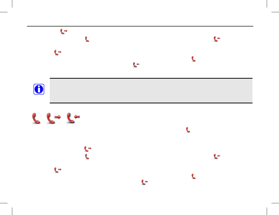
EMERGENCY COMMUNICATIONS
Publication 14222-1150-2000, Rev. A 49
2. When the icon appears in the display, speak into the microphone to transmit voice audio.
The radio displays the icon when it is ready to receive. When a call is received, the icon appears.
3. After the voice cycle(s) expires, additional voice calls can be made by pressing the PTT key. When doing
so, the icon appears in the display and the LED indicator glows red. Release the PTT key to end the
voice call (transmission) on the emergency channel. The radio displays the icon and the LED indicator
flashes orange rapidly. If a call is received, the icon appears in the display.
To exit the emergency mode early, long-press the programmed Emergency shortcut key.
The following parameters are programmed by your radio dealer for the above mode:
• Number of voice cycles;
• Duration of each transmission; and,
• Transmission interval.
Call Only Emergency Mode
If the radio is programmed for Call Only
emergency mode operations on the
selected digital channel, use this mode as follows:
1. Press the programmed Emergency shortcut key. The radio displays a (red phone handset) icon and
switches to the dedicated/revert channel for the emergency call.
2. If the “Alarm with Call to Follow” feature is enabled, voice audio can be transmitted by speaking into the
microphone when the icon appears in the display.
The radio displays the icon when it is ready to receive. When a call is received, the icon appears.
3. After the voice cycle(s) expires, additional voice calls can be made by pressing the PTT key. When doing
so, the icon appears in the display and the LED indicator glows red. Release the PTT key to end the
voice call (transmission) on the emergency channel. The radio displays the icon and the LED indicator
flashes orange rapidly. When a call is received, the icon appears in the display.
NOTE

EMERGENCY COMMUNICATIONS
50
To exit the emergency mode early, simply long-press the programmed Emergency shortcut key.
The following parameters are programmed by your radio dealer for the above mode:
• Number of voice cycles;
• Duration of each transmission;
• Transmission interval;
• Number of polite retires; and,
• Number of impolite retires.
LONE WORKER
The Lone Worker feature, when enabled, causes the radio to automatically transmit an alarm if the radio
user/operator does not react to reminder beeps which the radio periodically generates. Before this feature will
function, it must be programmed by your radio dealer and it must be enabled.
User/Operator reaction is accomplished by simply pressing any radio key or by rotating a radio knob before a
programmed reminder timer expires. Either reaction will reset the programmed reminder and response timers,
thus starting a new response period of time. The response timer is typically programmed for many minutes or
hours (255 minutes maximum), and the reminder timer is typically programmed for several seconds to a minute
(255 seconds maximum).
If no reaction is taken when the radio begins beeping and the response timer is allowed to expire, the radio
automatically enters the programmed emergency mode and if the selected channel is programmed for Alarm or
Alarm with Call emergency mode operations, it immediately begins alarm transmissions on the selected
channel, or on a channel pre-assign for emergency communications. However, the radio does not transmit if the
selected channel is not programmed for Alarm or Alarm with Call emergency mode operations.
Enabling and Disabling Lone Worker
There are two (2) possible ways to enable and disable the Lone Worker feature:
• From the Radio Set menu select: Menu > Settings > Radio Set > Lone Worker > Enable or Disable.
NOTE

EMERGENCY COMMUNICATIONS
Publication 14222-1150-2000, Rev. A 51
• If the Lone Worker shortcut key is programmed to a key, press this key to enable or disable the Lone
Worker feature.
When this feature is enabled (i.e., turned on), the radio briefly displays “Lone Worker On!” When this feature
is disabled (i.e., turned off), the radio briefly displays “Lone Worker Off!”
Using Lone Worker
1. Enable (i.e., turn on) the Lone Worker feature if it is not already. Refer to the previous section as
necessary. The current enable/disable status can be viewed from the Lone Worker menu.
2. Select a channel programmed for Alarm or Alarm with Call emergency mode signaling. Consult with radio
system administration personnel as necessary.
3. When the radio begins sounding reminder beeps, press any radio key to reset the response timer. If this
timer is not reset before it times-out, the radio will begin alarm transmissions per radio programming.
When transmitting, the LED indicator on the top of the radio lights red and “Sending Alarm” displays.
4. If the programmed emergency mode is Alarm with Call, the radio beeps once and enters a hot-mic period.
The icon displays and the LED indicator lights red. During this time, speak into the radio’s
microphone to transmit voice audio on the channel. Pressing the PTT key is not necessary.
5. Next, the radio enters a receive period, displaying the icon. During this time, listen for a voice reply to
the alarm and/or voice transmission. Adjust volume as necessary.
The hot-mic and receive periods may be programmed to repeat one or more times.
6. To exit the emergency mode, thus ending alarm and voice transmissions early, simply press the Emergency
Off shortcut key. If this shortcut key is not programmed, select another channel or cycle radio power to exit
the emergency mode.

EMERGENCY COMMUNICATIONS
52
MAN DOWN (OPTIONAL)
If installed in the radio, the Man Down feature can be used to automatically initiate an emergency when the
radio is positioned aslant for a programmed period of time.
If the radio has this optional feature, the radio may be programmed to automatically enable the feature upon
radio power-up. If a man down capable radio is not programmed in this manner, the Man Down feature must be
manually enabled before the feature will function.
Manually Enabling and Disabling Man Down
There are two (2) possible ways to manually enable and disable the Man Down feature:
• From the Man Down menu select: Menu > Settings > Radio Set > Man Down > Enable or Disable.
• If the Man Down shortcut key is programmed to a key, press this key to enable or disable the Man Down
feature. A high-pitched tone sounds to indicate the feature is enabled. A low-pitched tone sounds to
indicate the feature is disabled.
Using Man Down
1. Enable the Man Down feature if it is not already. Refer to the previous section as necessary. The current
enable/disable status can be viewed from the Man Down menu.
2. After the radio is positioned aslant for the preset period of time, it first sounds an alert tone. If it is not soon
returned to a near vertical/upright position, it enters the emergency mode and automatically begins
transmitting emergency alarm(s), as programmed.
3. To exit the emergency mode, thus ending the alarm transmission(s), return the radio to a (near)
vertical/upright position.

HDC1200 SIGNALING
Publication 14222-1150-2000, Rev. A 53
GENERAL INFORMATION
The radio supports HDC1200 signaling. This signaling is compatible with MDC1200 signaling. It supports
functions such as PTT ID signaling, emergency signaling, and signaling via selective call. These functions are
supported in both encode and decode modes.
TRANSMISSION (ENCODE)
PTT ID Transmission
Along with voice audio, the radio can transmit an HDC1200-encoded identification (ID) number on the selected
channel with each press of the radio’s PTT key. This is commonly referred to a “PTT ID.” Per radio
programming, the ID number can be sent when the PTT key is pressed (before voice audio is transmitted),
when the PTT key is released (after voice audio is transmitted), or both at press and release of the PTT key.
The radio can be programmed to either sound a tone when it is transmitting the encoded signal or sound beeps
after it has transmitted the encoded signal.
Private/Group/All Call Transmission (Selective Call via Contact List)
An HDC1200-
encoded signal can also be transmitted to a contact on
the radio’s Contact List as follows:
1. Use the Contact menu to access the Contact List and select the desired contact. The contact selection can be
a private call, a group call, or an all call. Alternately, if pre-programmed, press the Contact List shortcut
key to get to this list, and then make the desired selection.
2. After selecting the contact, depress the radio’s PTT key to transmit the pre-programmed PTT ID number
and voice audio to the selected contact, and speak into the microphone at a normal voice level. During the
transmission, the LED indicator glows red and the appropriate private call icon is displayed. The
icon is displayed for a private call. The icon is displayed for a group call. The icon is
displayed for an all call.
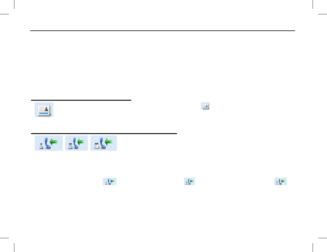
HDC1200 SIGNALING
54
3. Release the PTT key to stop transmitting, and listen for a reply. After the transmission, the LED indicator
briefly glows orange.
The radio can be programmed to either sound a tone when it is transmitting the encoded signal or sound beeps
after it has transmitted the encoded signal.
RECEPTION (DECODE)
The radio can be programmed to display HDC1200 signaling information it receives, as described in the
following subsections:
Indications for Received PTT IDs
After decoding a received PTT ID, the radio displays the
icon and either the ID or the alias
(name) of the transmitting radio.
If the alias of the received ID is not in the radio’s Contact List, the
ID is displayed. If the alias of the received ID is in the radio’s Contact List, the alias is displayed.
Indications for Received Private/Group/All Calls
Up
on decoding HDC1200 signaling information received via a private
call/group call/all call, the radio sounds the default alert tone and lights
the LED indicator green.
Also, if the radio is programmed with the “Display Decode ID” feature, it will display the respective selective
call icon and the ID or alias of the transmitting radio. If the alias of the received ID is not in the radio’s Contact
List, the ID is displayed. If the alias of the received ID is in the radio’s Contact List, the alias is displayed.
Selective call icons include for received private calls, for received group calls, and for
received all calls.
If the radio is not programmed with the “Display Decode ID” feature, it will only display the respective
selective call icon.

SECURE COMMUNICATIONS
Publication 14222-1150-2000, Rev. A 55
GENERAL INFORMATION
The radio’s Scrambler feature for analog channels can be used to reduce the likelihood of someone
“eavesdropping” via analog radio channels. This feature employs analog voice inversion technology.
This feature can be enabled and disabled on a per-channel basis.
The radio’s Encrypt feature for digital channels can be used to prevent “eavesdropping” via the digital radio
channel. This feature employs 256-bit digital AES encryption technology. This feature ensures the best
guarantee of communication privacy. This feature can be enabled and disabled on a per-channel basis.
OPERATION
The Scrambler/Encrypt feature may be programmed to automatically enable when a channel is selected, or it
may be manually enabled. When this feature is enabled/active, the icon appears in the display.
Manually Enabling and Disabling Scrambler/Encrypt
There are two (2) possible ways to enable and disable the Scrambler/Encryption feature:
• Scrambler: With an analog channel selected, choose: Menu > Settings > Radio Set > Scrambler >
Enable or Disable.
Encrypt: With a digital channel selected, choose: Menu > Settings > Radio Set > Encrypt > Enable or
Disable.
• If the Scrambler or Encrypt shortcut key is programmed to a key, press this key to enable or disable the
feature. A high-pitched tone sounds to indicate the feature is enabled. A low-pitched tone sounds to
indicate the feature is disabled.

MISCELLANEOUS FEATURES
56
CHANNEL BUSY LOCKOUT
If enabled via the programming software, this feature can prevent the radio from interfering with other
transmitting radios on the same channel. If the PTT key is held down while the channel is in use, the radio will
keep beeping and display “Channel Busy!” alerting of the transmission prohibition. To stop the beeping, release
the PTT key. When the channel is free, press and hold down the PTT key to transmit.
TIME-OUT TIMER (TOT)
The purpose of Time-Out-Timer (TOT) is to prevent any user from occupying a channel for an extended period.
If the preset time expires, the radio will automatically terminate transmission and keep beeping. To stop the
beeping, release the PTT key. You must wait for a certain time period (preset by your dealer) to initiate another
transmission. If the pre-alert function is set by your dealer, the radio will alert you to the TOT expiration in
advance.
This feature does not function when the radio is in an emergency mode.
PSEUDO TRUNKING
This feature can be enabled via the programming software. If the radio operates on a digital channel with this
feature enabled and one digital time slot is already occupied, the radio can transmit and receive on the other free
digital time slot, allowing communications to continue during busy periods.
MIC AGC
If enabled via the programming software, the radio will process the audio signals during transmission,
providing improved audio for the receiving radio.
NOTE

MISCELLANEOUS FEATURES
Publication 14222-1150-2000, Rev. A 57
RADIO REGISTRATION SERVICE
If enabled by your dealer, the radio will automatically register in the system within a certain period after power-
on. When registered, it can acquire online information of other radios by accessing specific servers within the
valid registration period.
GPS REVERT
If enabled by your dealer, a registered radio will transmit GPS positioning information to the radio system when
the system requests it.
ONE TOUCH CALL
The radio can be programmed by your radio dealer with the One Touch Call feature. This feature allows any
one of the following pre-programmed calls via a programmed shortcut key:
• On an analog channel, send 5-tone signaling call to a contact.
• On an analog channel, send 2-tone signaling call to a contact.
• On a digital channel, send group calls or messages to the Group Call contact.
• On a digital channel, send private calls, messages or make control services to the Private Call contact.
Control services include: Alert Call, Radio Check, Remote Monitor, Radio Enable or Radio Disable, as
described in the Manual Dial section (31 page).
One Touch Call Operation
Consult with your radio dealer as necessary to determine specific programming and operation details specific to
your radio. Basic operations include:
• To send a private call or a group call on a digital channel, select the channel, press the programmed One
Touch Call shortcut key, and then hold down the PTT key and speak into the microphone to transmit
voice audio. Release the PTT key when you finish speaking.

MISCELLANEOUS FEATURES
58
• To send a call on an analog channel, select the channel and then press the programmed One Touch Call
shortcut key.
• To send a message on a digital channel, select the channel and then press the programmed One Touch
Call shortcut key.
• To send control service commands on a digital channel, select the channel and then press the programmed
One Touch Call shortcut key.
TELEMETRY
The Telemetry feature allows you to remotely supervise a device connected to a radio. With this feature, you
can control the device and view its status remotely. The method for supervising the device is programmable by
your dealer. These methods are described in the following subsections.
Supervise a Device via Another/Remote Radio
If a device is connected with a radio, you can use another/remote radio to supervise the device. All the radios
involved should be configured with the Telemetry feature. For example, the dealer enables the Telemetry
feature for both Radio A and Radio B, and assigns the Telemetry feature to the SK1 key on Radio A. To
supervise the device C, connect it with Radio B, and press the SK1 key on Radio A.
Supervise a Device via Third-Party Software
If the Telemetry feature is enabled for the radio by your radio dealer, you can supervise the device connected
with the radio via third-party software.
ROAM
This feature allows the radio to communicate between sites in the IP multisite-connected radio system. If
enabled, the radio can communicate via any site in the multisite system, thus ensuring seamless radio
communication in the system.

MISCELLANEOUS FEATURES
Publication 14222-1150-2000, Rev. A 59
Use one of these methods to enable or disable roaming:
• From the home screen, press the Menu key then select Roaming > On or Off.
• Press the programmed Roam shortcut key to toggle roaming on or off.
5-TONE SIGNALING
The radio supports 5-tone signal encode and decode operation as follows:
5-Tone Signaling Encode
1. Have your radio dealer configure the correct format and type for the encoding contents.
2. When the format consists of fields for variable information, you need to fill in such fields by manual entry
or menu operation.
When the format consists of fixed codes only, you do not have to edit any fields or save any data.
3. To send the 5-tone signaling, press PTT or the programmed One Touch Call 1 to One Touch Call 5
shortcut key.
When encoding, the radio sounds a tone, the LED indicator glows red, and the contact information (or “Five
Tone Call”) and an appropriate call icon (Private Call: or Group Call:) is displayed. If Auto Reset is enabled (by
your dealer), the radio enters the Auto Reset mode after successful encoding, with LED indicator glowing
orange until the Auto Reset Time expires.
5-Tone Signaling Decode
The radio can automatically decode the 5-tone signaling when receiving any matched one.
When decoding, the LED indicator glows green. After successful decoding, the display shows the contact
information (or “Five Tone Call”), an appropriate call icon (Private Call: or Group Call:), and the decoded
status message. If Auto Reset is enabled (by your dealer), the radio enters the Auto Reset mode, with LED
indicator glowing orange until the Auto Reset Time expires.

MISCELLANEOUS FEATURES
60
2-TONE SIGNALING
The radio supports 2-tone signal encode and decode operation as follows:
2-Tone Signaling Encode
1. Have your radio dealer configure the correct format and type for the encoding contents.
2. To send the 2-tone signaling, press the PTT key or the programmed One Touch 1 to One Touch 5
shortcut key.
When encoding, the radio sounds a tone, the LED indicator glows red, and the call icon with the
contact information above it. If Auto Reset is enabled (by your dealer), the radio enters the Auto Reset mode
after successful encoding, with LED indicator glowing orange until the Auto Reset Time expires.
2-Tone Signaling Decode
Your radio can automatically decode the 2-tone signaling. When decoding a matched one, the LED indicator
glows green. After successful decoding, the display shows the contact information (or “Five Tone Call”), the
and the call type (selective call, alert call with voice, alert call) below the icon according the decoding
type. If Auto Reset is enabled (by your dealer), the radio enters the Auto Reset mode, with LED indicator
glowing orange until the Auto Reset Time expires.
ENTERING LETTERS, NUMBERS, AND OTHER CHARACTERS VIA THE KEYPAD
Upper and Lower Case Letters
To enter text via the radio’s keypad:
1. Press the key to switch between upper case and lower case letters.
2. Press the key that has the desired letter repeatedly until the desired letter appears in the display.
3. To enter a space, press the key.

MISCELLANEOUS FEATURES
Publication 14222-1150-2000, Rev. A 61
4. Repeat steps 1 through 3 as necessary to complete a word or sentence.
Numbers
To enter text via the radio’s keypad:
1. Press the key to switch to number mode.
2. Enter the desired number by pressing the through alphanumeric keys.
3. Repeat steps 1 and 2 as necessary to complete a word or sentence.
Punctuation Characters and Special Characters
To enter common punctuation characters and special characters, press the key one or more times until the
desired character appears in the display.
To enter a space, press the key.

TROUBLESHOOTING AND TECHNICAL ASSISTANCE
62
TROUBLESHOOTING TABLE
SYMPTOM POSSIBLE PROBLEMS SOLUTIONS
Radio will not turn on.
Battery is dead. Charge or replace the battery. See page 10
for instructions.
Battery is not properly attached to the
radio. Remove and then re-attach the battery to the
radio. See page 11 for instructions.
Battery is defective/bad. Replace the battery with a fully-
charged
battery.
When receiving, voice
audio is weak, erratic,
or not present at all.
Volume is set too low. Increase the volume with the On/Off Volume
Control knob. See page 18.
Antenna is not properly connected to
the radio. Turn the radio off, re-
connect the antenna
cable to the radio, and turn the radio back on.
Antenna is damaged or not present.
Have your radio dealer repair/replace the
antenna.
Speaker may be blocked or damaged.
Clean surface of the speaker. If the problem
cannot be solved, contact your dealer or
an
authorized service
center for inspection and
repair.
On an analog
channel, you cannot
communicate with
others.
The frequency or signaling may not be
the same as the other radios.
Verify selected channel is correct and/or
consult with your radio dealer to verify the
programming of the channel’s frequency and
signaling.
Out-of-range (too far away) from other
radios, or from the channel’s respective
repeater/base station.
Change your location. Moving a few
yards/meters in one direction can sometimes
greatly improve communications range.

TROUBLESHOOTING AND TECHNICAL ASSISTANCE
Publication 14222-1150-2000, Rev. A 63
SYMPTOM POSSIBLE PROBLEMS SOLUTIONS
On an analog
channel, irrelevant
communications
and/or noises are
heard.
Other radios may be using the same
radio frequency.
Adjust the squelch and/or consult with your
radio dealer as necessary.
The radio may be programmed without
signaling, but signaling is needed. Consult with your radio dealer as necessary.
On a digital channel,
you cannot
communicate with
others but there is a
receive indication.
The ID may be inconsistent with other
members. (The digital signal is being
received but not fully demodulated.)
Set the ID to the same as the other member’s
radios. Consult with your radio dealer as
necessary.
Noisy
communications.
Out-of-
range (too far away from) of
others, or from the channel’s repeater/-
base station.
Change your location. Moving a few
yards/meters in one direction
or moving to a
higher elevation
can sometimes greatly
improve communications range.
A nearby device, such as an electric
motor or light bulb, is causing interfe-
rence on the radio frequency/channel.
Change your location. Moving a few
yards/meters in one direction can sometimes
greatly improve communications.
Keypad does not
operate. The keypad has temporarily failed.
Restart the radio by turning it off and back
on.
Display does not
operate. The display has temporarily failed.
Restart the radio by turning it off and back
on.
GPS cannot
determine
location/position
The GPS antenna is improperly con-
nected to the radio, or the antenna is
damaged/missing.
Connect the antenna and/or consult with your
radio dealer as necessary.
No GPS signal is being received. Change your location and re-
check for a
signal.

TROUBLESHOOTING AND TECHNICAL ASSISTANCE
64
TECHNICAL ASSISTANCE
When technical issues arise that cannot be resolved using the troubleshooting table, contact your radio
equipment dealer for solution assistance. Also contact your radio equipment dealer for specific information
about how the radio is programmed.
CARE AND CLEANING
Publication 14222-1150-2000, Rev. A 65
Ensure optimal radio performance as well as a long service life by following these care and cleaning tips:
RADIO CARE
• Review and follow all precautions described in the radio’s Product Safety Booklet.
• Do not hold the radio by its antenna or by a cable connected to its accessory connector.
• Do not pierce or scrape the surface of the radio or its accessories.
• Always replace the accessory connector’s cover when an accessory cable is not connected to the radio.
• Do not place the radio or any radio accessories in corrosive agents, solutions, gas mixers, or water.
RADIO CLEANING
Turn the radio off before cleaning it.
• On a regular basis, clean dust and fine particles from the radio and any accessories with a clean, dry, lint-
free cloth or a fine brush.
• After long periods of use, gently clean the radio’s keys, control knobs, display, and jacks/connectors with a
non-woven fabric and a neutral-base cleanser or mild soap. Do not use chemical preparations such as stain
removers, alcohol, sprays, or oils.
• Always allow the radio and its accessories to dry completely before turning the radio back on.
CAUTION

MODEL NUMBERS
66
RADIO PACKAGES
MODEL NUMBER DESCRIPTION
HD-PFV1B Momentum HDP150 Portable Radio, 136 to 174 MHz, with GPS and Stan-
dard Accessories
HD-PFV1B-MD Momentum HDP150 Portable Radio, 136 to 174 MHz, with GPS and Man
Down, and Standard Accessories
HD-PFV1B-TXR Momentum HDP150 Portable Radio, 136 to 174 MHz, with GPS (radio only)
HD-PFV1B-MD-TXR Momentum HDP150 Portable Radio, 136 to 174 MHz, with GPS and Man
Down (radio only)
HD-PFU1B Momentum HDP150 Portable Radio, 400 to 470 MHz, with GPS and Stan-
dard Accessories
HD-PFU1B-MD Momentum HDP150 Portable Radio, 400 to 470 MHz, with GPS and Man
Down, and Standard Accessories
HD-PFU1B-TXR Momentum HDP150 Portable Radio, 400 to 470 MHz, with GPS (radio only)
HD-PFU1B-MD-TXR Momentum HDP150 Portable Radio, 400 to 470 MHz, with GPS and Man
Down (radio only)
HD-PFU2B Momentum HDP150 Portable Radio, 450 to 520 MHz, with GPS and Stan-
dard Accessories
HD-PFU2B-MD Momentum HDP150 Portable Radio, 450 to 520 MHz, with GPS and Man
Down, and Standard Accessories
HD-PFU2B-TXR Momentum HDP150 Portable Radio, 450 to 520 MHz, with GPS (radio only)
HD-PFU2B-MD-TXR Momentum HDP150 Portable Radio, 450 to 520 MHz, with GPS and Man
Down (radio only)
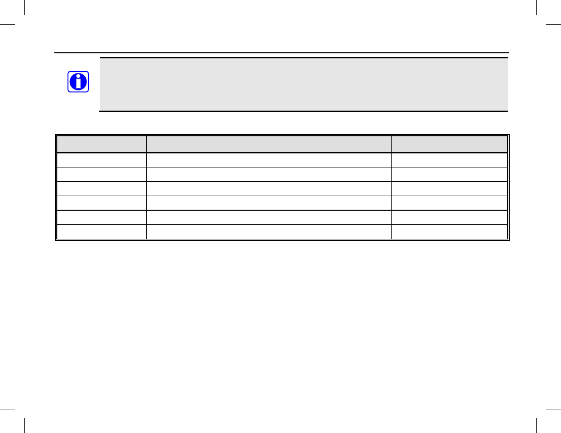
MODEL NUMBERS
Publication 14222-1150-2000, Rev. A 67
Standard accessories include one of each item pictured on page 5 (less the radio). Respective part
numbers are listed in the tables that follow. Each radio is supplied with one (1) standard antenna,
one (1) standard battery, one (1) standard battery charger with power adapter, and various
carrying accessories as pictured on page 5.
ANTENNAS
MODEL NUMBER DESCRIPTION STANDARD/OPTIONAL
HD-AN6K-01 Antenna, 136 to 147 MHz, Long Standard
HD-AN6K-02 Antenna, 136 to 174 MHz, Long Standard
HD-AN6K-03 Antenna, 147 to 160 MHz, Long Standard
HD-AN6K-04 Antenna, 160 to 174 MHz, Long Standard
HD-AN6L-03 Antenna, 400 to 470 MHz, Stub Standard
HD-AN6L-04 Antenna, 450 to 520 MHz, Stub Standard
NOTE

MODEL NUMBERS
68
BATTERIES AND BATTERY CHARGERS
MODEL NUMBER DESCRIPTION STANDARD/OPTIONAL
HD-PA2V Battery, Lithium-Ion 2000 mAH Standard
HD-PA2Y Battery, Lithium-Ion 2500 mAH Optional
HD-CH4D Charger, Battery: 1-Bay with Power Adapter Standard
HD-CH4F Charger, Battery: 6-Bay Optional
HD-PS2V Power Supply, 6-Unit, Switching Optional
HD-PS2T Adapter, AC Power, 100 to 240 Vac at 50/60 Hz
Input, 12 Vdc Output Optional
CARRYING ACCESSORIES
MODEL NUMBER DESCRIPTION STANDARD/OPTIONAL
HD-HC3M Clip, Belt Standard
HD-HC3R Strap, Wrist Standard
HD-CL3N Case, Leather with Swivel Optional

MODEL NUMBERS
Publication 14222-1150-2000, Rev. A 69
AUDIO ACCESSORIES
MODEL NUMBER DESCRIPTION STANDARD/OPTIONAL
HD-AE6P Earpiece with On-Mic PTT Optional
HD-AE6R Earpiece with 3-Wire Surveillance Kit Optional
HD-AE6S D-Earset with In-Line Mic and PTT Optional
HD-AE6U Earbud with On-Mic PTT Optional
HD-AE6V Earbud, Receive-Only Optional
HD-AE6W Speaker-Mic, Waterproof Optional
HD-AE6Y Earpiece, Receive-Only Optional
HD-AE6Z Earpiece, 2-Wire, Wireless Earphone/Neck Optional

WARRANTY REGISTRATION AND WARRANTY
70
WARRANTY REGISTRATION
Please register this product within ten (10) days of purchase. Registration validates the warranty coverage, and
enables Harris to contact you in case of any safety notifications issued for this product.
Registration can be made on-line at http://www.pspc.harris.com/Service/WarrantySupport.asp.
EQUIPMENT AND RECHARGEABLE BATTERY WARRANTY
A. Harris Corporation, a Delaware Corporation, acting through its RF Communications Division (hereinafter
"Seller") warrants to the original purchaser for use (hereinafter "Buyer") that Momentum™ Equipment
manufactured by or for the Seller shall (i) be free from all defects in material, workmanship and title; and (ii)
comply with all of the Momentum™ Equipment Product Specifications. For purposes of this warranty,
batteries shall be deemed defective if: (1) the battery capacity is less than 80% rated capacity, or (2) the
battery develops leakage.
B. Seller’s obligations set forth in Paragraph C below shall apply only to Momentum™ Equipment failures to
meet the above warranties occurring within the following periods of time from the date of sale to the Buyer
and are conditioned on Buyer’s giving written notice to Seller within thirty (30) days of such occurrence:
1. for portable radios, mobile radios, repeaters and base stations, thirty-six (36) months (except as noted
in paragraph B.2 and B.3);
2. rechargeable batteries and accessories, twelve (12) months; and,
3. all other parts, ninety (90) days.
C. If any Momentum™ Equipment fails to meet the foregoing warranties, Seller shall correct the failure at its
option (i) by repairing any defective or damaged part or parts thereof, or (ii) by replacing the failed
Momentum™ Equipment with equivalent new or refurbished Equipment. Any repaired or replacement
products or parts furnished hereunder shall be warranted for the balance of the original applicable Product
Warranty Period or one hundred eighty (180) days for Products (other than batteries, accessories and parts)
and ninety (90) days for batteries and accessories, whichever ends later. Where such failure cannot be
corrected by Seller’s reasonable efforts, the parties will negotiate an equitable adjustment in price. Labor to
perform warranty service will be provided at no charge during the warranty period only for the Equipment

WARRANTY REGISTRATION AND WARRANTY
Publication 14222-1150-2000, Rev. A 71
covered under Paragraph B. To be eligible for no-charge labor, service must be performed at Seller’s
location or other Servicer approved by Seller in writing to make the specific repairs at its place of business
during normal business hours. Seller shall pay all freight charges relating to the return and shipment of the
defective Products and the repaired or replacement Products to and from the Seller designated location. If it
is determined that the Products are not under warranty, Buyer shall pay all freight charges related to the
return and shipment of the Products and the repaired or replacement Products to and from the Seller
designated location.
D. Seller’s obligations under Paragraph C shall not apply to any Equipment or part thereof, which:
1. has a defect that is not reported during the Product Warranty Period;
2. is disassembled, modified, altered or repaired other than pursuant to Seller’s written instructions or
other written approval by Seller;
3. is not installed, operated or maintained in accordance with written instructions provided by Seller;
4. has its serial number removed or altered;
5. is not properly stored or suffers detrimental exposure or is treated with abuse, negligence or other
improper treatment; or,
6. is damaged in an accident or in a natural disaster (earthquake, storm, flood, fire or other natural
disaster).
E. The preceding paragraphs set forth the exclusive remedies for claims based upon defects in or
nonconformity of the Momentum™ Equipment, whether the claim is in contract, warranty, tort (including
negligence), strict liability or otherwise and however instituted. Upon the expiration of the warranty period, all
such liability shall terminate. The foregoing warranties are exclusive and in lieu of all other warranties,
whether oral, written, expressed, implied or statutory. NO IMPLIED OR STATUTORY WARRANTIES OF
MERCHANTABILITY OR FITNESS FOR PARTICULAR PURPOSE SHALL APPLY. IN NO EVENT SHALL
THE SELLER BE LIABLE FOR ANY INCIDENTAL, CONSEQUENTIAL, SPECIAL, INDIRECT OR
EXEMPLARY DAMAGES.
This warranty applies only within the United States.
Contact your local Harris Dealer to request warranty service. ECR-7931