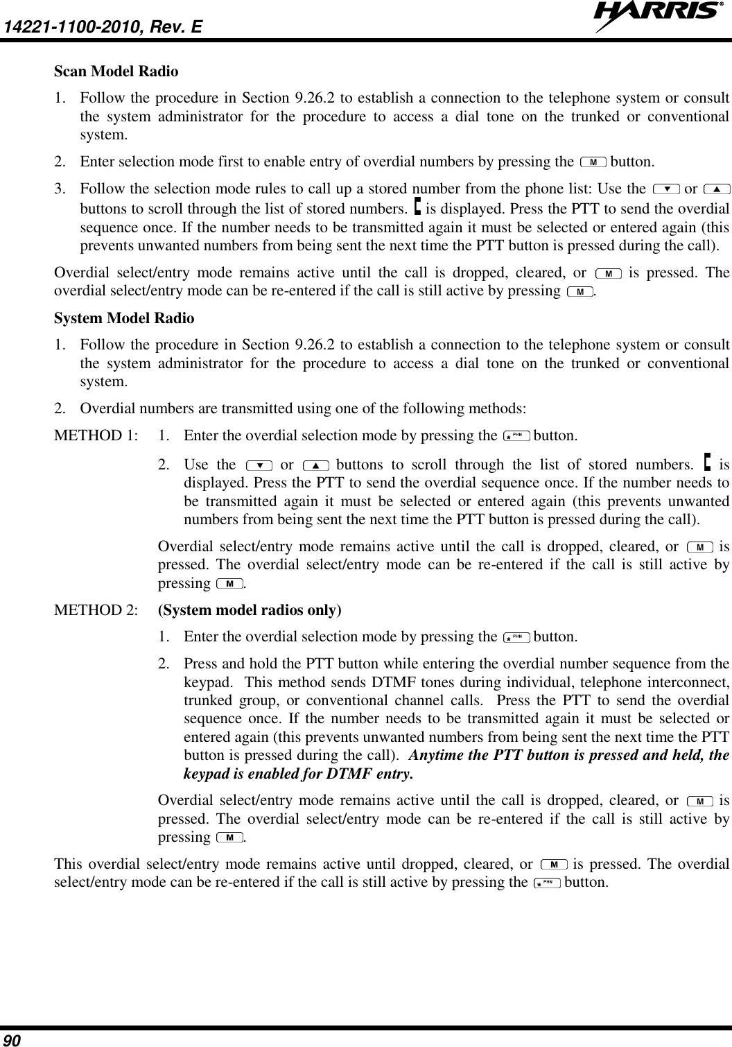
HARRIS TR-0131-E XG-75 UHF-H User Manual FCC IC Certification Report
HARRIS CORPORATION XG-75 UHF-H FCC IC Certification Report
UserManual.wiki
>
HARRIS
>
TR 0131 E User Manual
User Manual
Navigation menu
Upload a User Manual
Namespaces
Wiki Guide
HTML
PDF
Info
Views
User Manual
Discussion / Help
Navigation

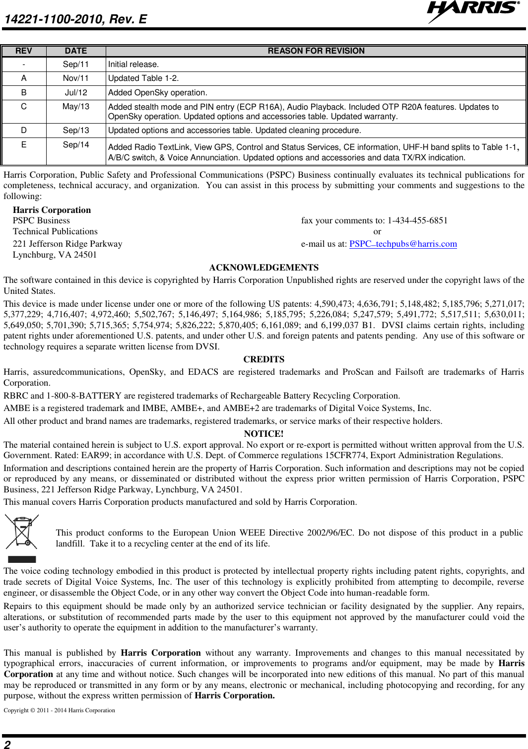
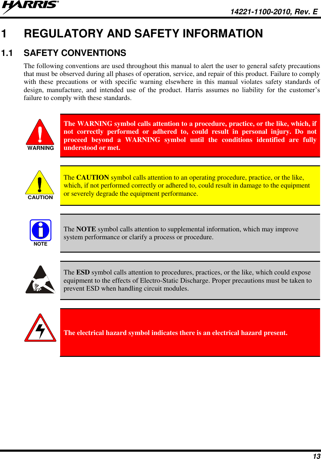
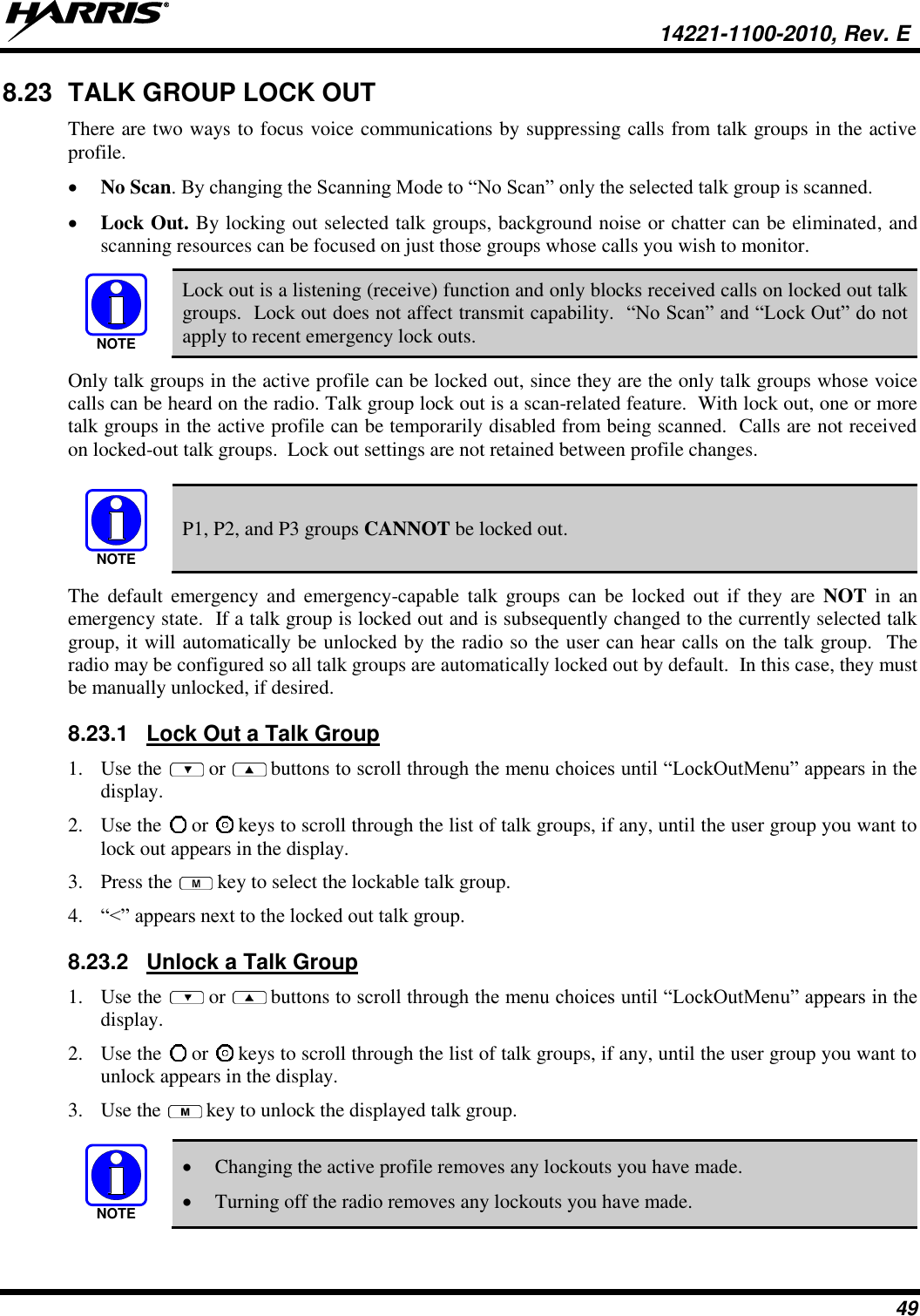
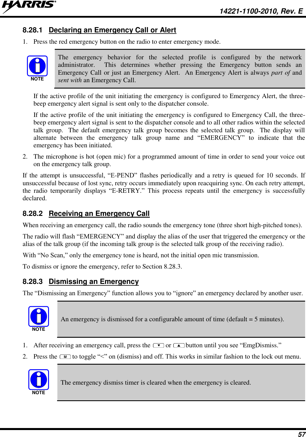
![14221-1100-2010, Rev. E 5 Česky [Czech] Harris Corporation tímto prohlašuje, že tento XG-75P VHF (136 – 174 MHz) UHF-L (378 – 470 MHz) je ve shodě se základními požadavky a dalšími příslušnými ustanoveními směrnice 1999/5/ES. Dansk [Danish] Undertegnede Harris Corporation erklærer herved, at følgende udstyr XG-75P VHF (136 – 174 MHz) UHF-L (378 – 470 MHz) overholder de væsentlige krav og øvrige relevante krav i direktiv 1999/5/EF. Deutsch [German] Hiermit erklärt Harris Corporation, dass sich das Gerät XG-75P VHF (136 – 174 MHz) UHF-L (378 – 470 MHz) in Übereinstimmung mit den grundlegenden Anforderungen und den übrigen einschlägigen Bestimmungen der Richtlinie 1999/5/EG befindet. Eesti [Estonian] Käesolevaga kinnitab Harris Corporation seadme XG-75P VHF (136 – 174 MHz) UHF-L (378 – 470 MHz) vastavust direktiivi 1999/5/EÜ põhinõuetele ja nimetatud direktiivist tulenevatele teistele asjakohastele sätetele. English Hereby, Harris Corporation, declares that this XG-75P VHF (136 – 174 MHz) UHF-L (378 – 470 MHz) is in compliance with the essential requirements and other relevant provisions of Directive 1999/5/EC. Español [Spanish] Por medio de la presente Harris Corporation declara que el XG-75P VHF (136 – 174 MHz) UHF-L (378 – 470 MHz) cumple con los requisitos esenciales y cualesquiera otras disposiciones aplicables o exigibles de la Directiva 1999/5/CE. Ελληνική [Greek] ΜΕ ΤΗΝ ΠΑΡΟΥΣΑ Harris Corporation ΔΗΛΩΝΕΙ ΟΤΙ XG-75P VHF (136 – 174 MHz) UHF-L (378 – 470 MHz) ΣΥΜΜΟΡΦΩΝΕΤΑΙ ΠΡΟΣ ΤΙΣ ΟΥΣΙΩΔΕΙΣ ΑΠΑΙΤΗΣΕΙΣ ΚΑΙ ΤΙΣ ΛΟΙΠΕΣ ΣΧΕΤΙΚΕΣ ΔΙΑΤΑΞΕΙΣ ΤΗΣ ΟΔΗΓΙΑΣ 1999/5/ΕΚ. Français [French] Par la présente Harris Corporation déclare que l'appareil XG-75P VHF (136 – 174 MHz) UHF-L (378 – 470 MHz) est conforme aux exigences essentielles et aux autres dispositions pertinentes de la directive 1999/5/CE. Italiano [Italian] Con la presente Harris Corporation dichiara che questo XG-75P VHF (136 – 174 MHz) UHF-L (378 – 470 MHz) è conforme ai requisiti essenziali ed alle altre disposizioni pertinenti stabilite dalla direttiva 1999/5/CE. Latviski [Latvian] Ar šo Harris Corporation deklarē, ka UHF-L XG-75P (378 – 470 MHz) atbilst Direktīvas 1999/5/EK būtiskajām prasībām un citiem ar to saistītajiem noteikumiem. Lietuvių [Lithuanian] Šiuo Harris Corporation deklaruoja, kad šis XG-75P VHF (136 – 174 MHz) UHF-L (378 – 470 MHz) atitinka esminius reikalavimus ir kitas 1999/5/EB Direktyvos nuostatas. Nederlands [Dutch] Hierbij verklaart Harris Corporation dat het toestel XG-75P VHF (136 – 174 MHz) UHF-L (378 – 470 MHz) in overeenstemming is met de essentiële eisen en de andere relevante bepalingen van richtlijn 1999/5/EG. Malti [Maltese] Hawnhekk, Harris Corporation, jiddikjara li dan XG-75P VHF (136 – 174 MHz) UHF-L (378 – 470 MHz) jikkonforma mal-ħtiġijiet essenzjali u ma provvedimenti oħrajn relevanti li hemm fid-Dirrettiva 1999/5/EC. Magyar [Hungarian] Alulírott, Harris Corporation nyilatkozom, hogy a XG-75P VHF (136 – 174 MHz) UHF-L (378 – 470 MHz) megfelel a vonatkozó alapvetõ követelményeknek és az 1999/5/EC irányelv egyéb elõírásainak. Polski [Polish] Niniejszym Harris Corporation oświadcza, że XG-75P VHF (136 – 174 MHz) UHF-L (378 – 470 MHz) jest zgodny z zasadniczymi wymogami oraz pozostałymi stosownymi postanowieniami Dyrektywy 1999/5/EC. Português [Portuguese] Harris Corporation declara que este XG-75P VHF (136 – 174 MHz) UHF-L (378 – 470 MHz) está conforme com os requisitos essenciais e outras disposições da Directiva 1999/5/CE.](https://usermanual.wiki/HARRIS/TR-0131-E/User-Guide-2394040-Page-6.png)
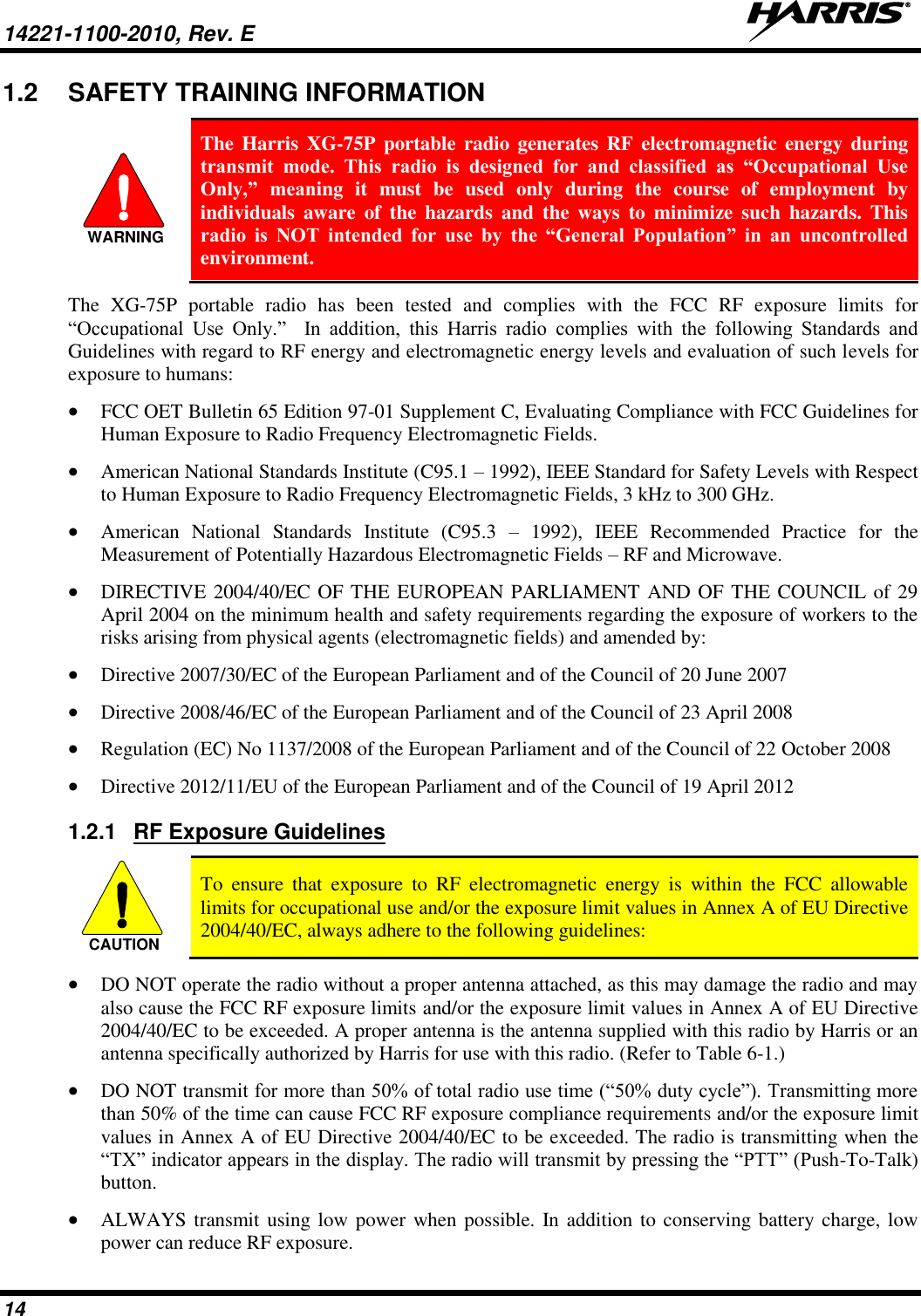
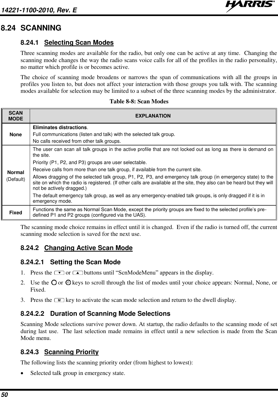
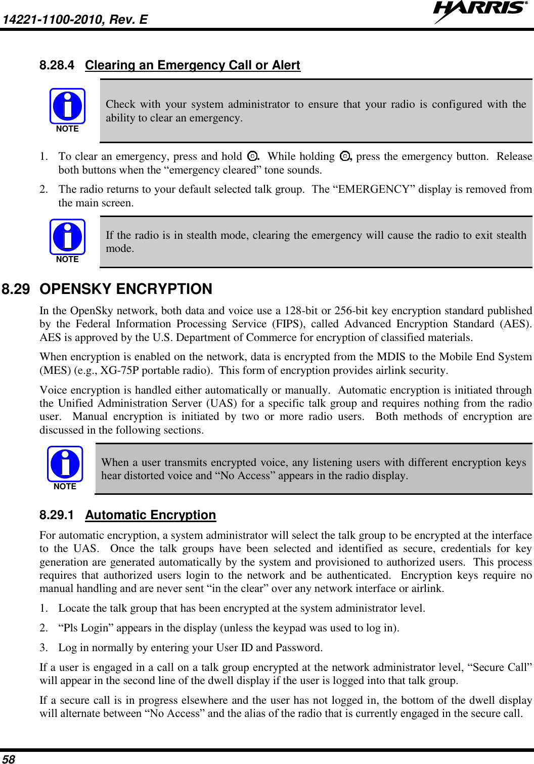
![14221-1100-2010, Rev. E 6 Slovensko [Slovenian] Harris Corporation izjavlja, da je ta XG-75P VHF (136 – 174 MHz) UHF-L (378 – 470 MHz) v skladu z bistvenimi zahtevami in ostalimi relevantnimi določili direktive 1999/5/ES. Slovensky [Slovak] Harris Corporation týmto vyhlasuje, že XG-75P VHF (136 – 174 MHz) UHF-L (378 – 470 MHz) spĺňa základné požiadavky a všetky príslušné ustanovenia Smernice 1999/5/ES. Suomi [Finnish] Harris Corporation vakuuttaa täten että XG-75P VHF (136 – 174 MHz) UHF-L (378 – 470 MHz) tyyppinen laite on direktiivin 1999/5/EY oleellisten vaatimusten ja sitä koskevien direktiivin muiden ehtojen mukainen. Svenska [Swedish] Härmed intygar Harris Corporation att denna XG-75P VHF (136 – 174 MHz) UHF-L (378 – 470 MHz) står I överensstämmelse med de väsentliga egenskapskrav och övriga relevanta bestämmelser som framgår av direktiv 1999/5/EG. Íslenska [Icelandic] Hér með lýsir Harris Corporation yfir því að XG-75P VHF (136 – 174 MHz) UHF-L (378 – 470 MHz) er í samræmi við grunnkröfur og aðrar kröfur, sem gerðar eru í tilskipun 1999/5/EC. Norsk [Norwegian] Harris Corporation erklærer herved at utstyret XG-75P VHF (136 – 174 MHz) UHF-L (378 – 470 MHz) er i samsvar med de grunnleggende krav og øvrige relevante krav i direktiv 1999/5/EF.](https://usermanual.wiki/HARRIS/TR-0131-E/User-Guide-2394040-Page-7.png)
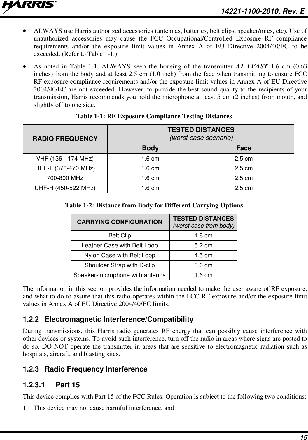
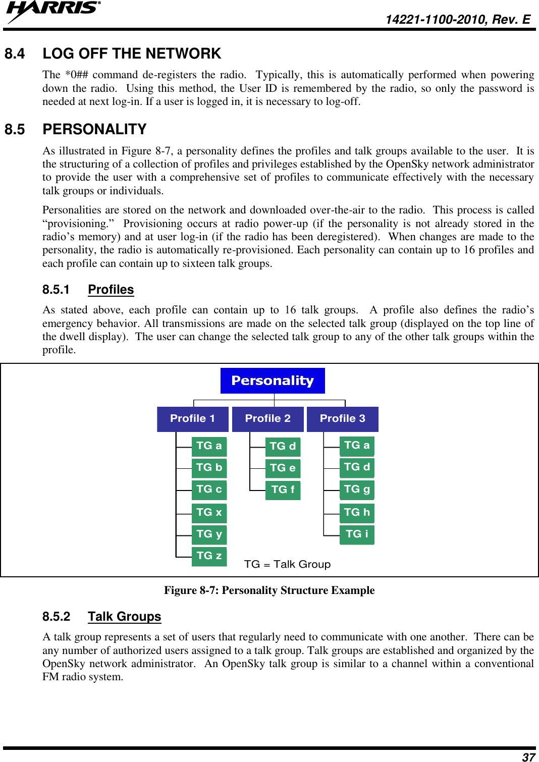
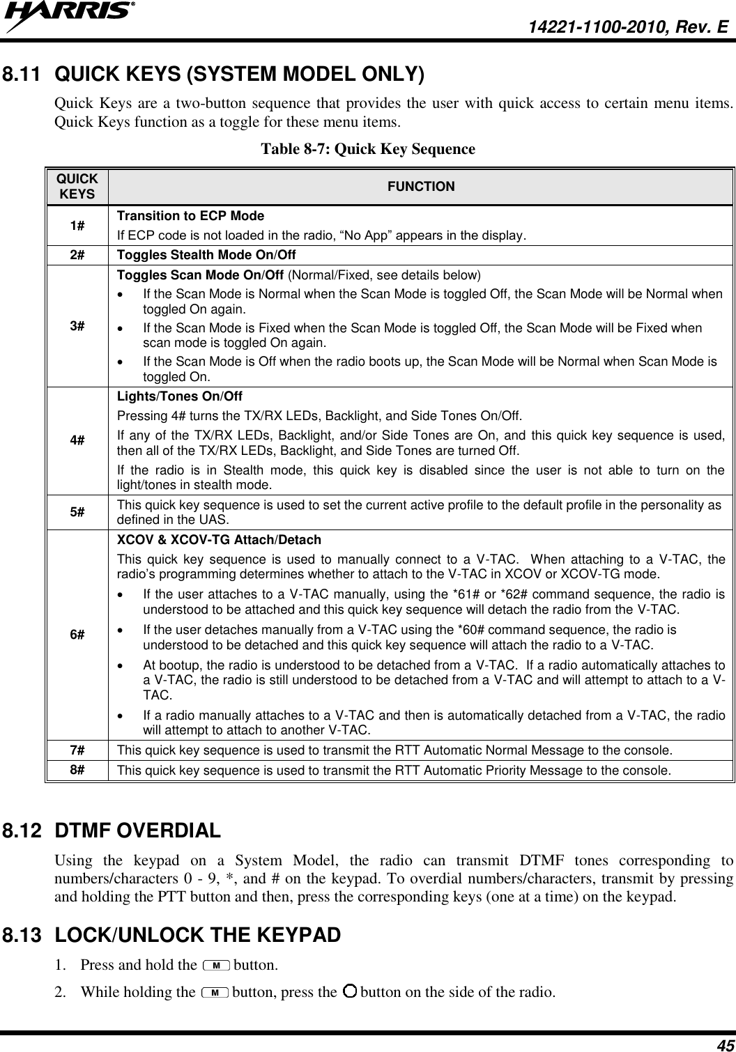
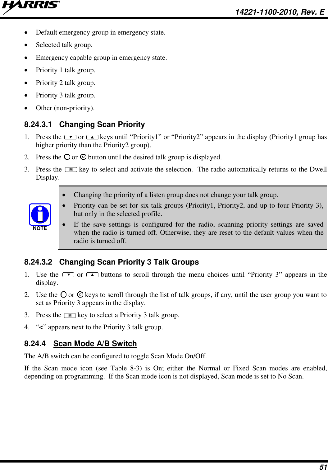
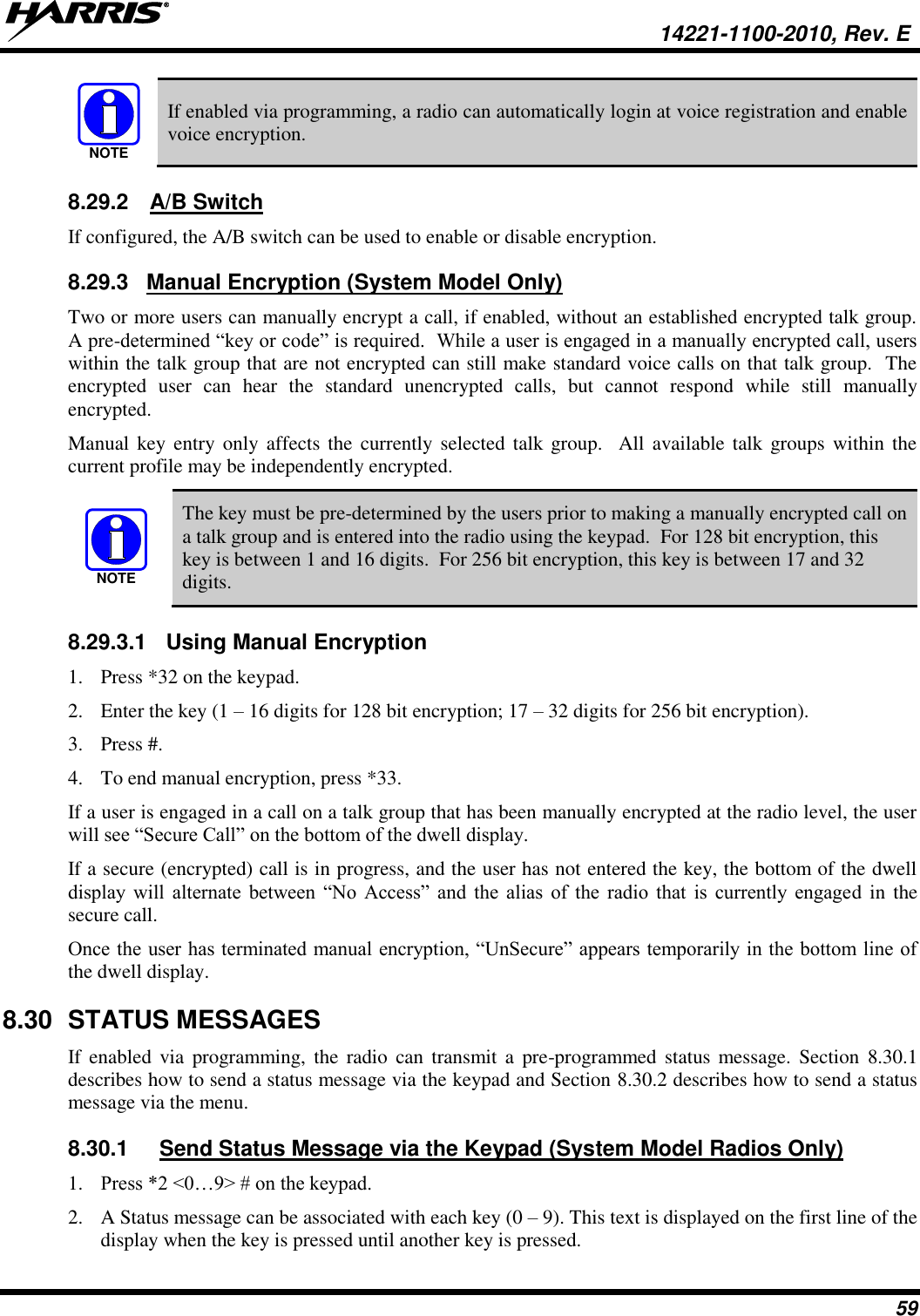
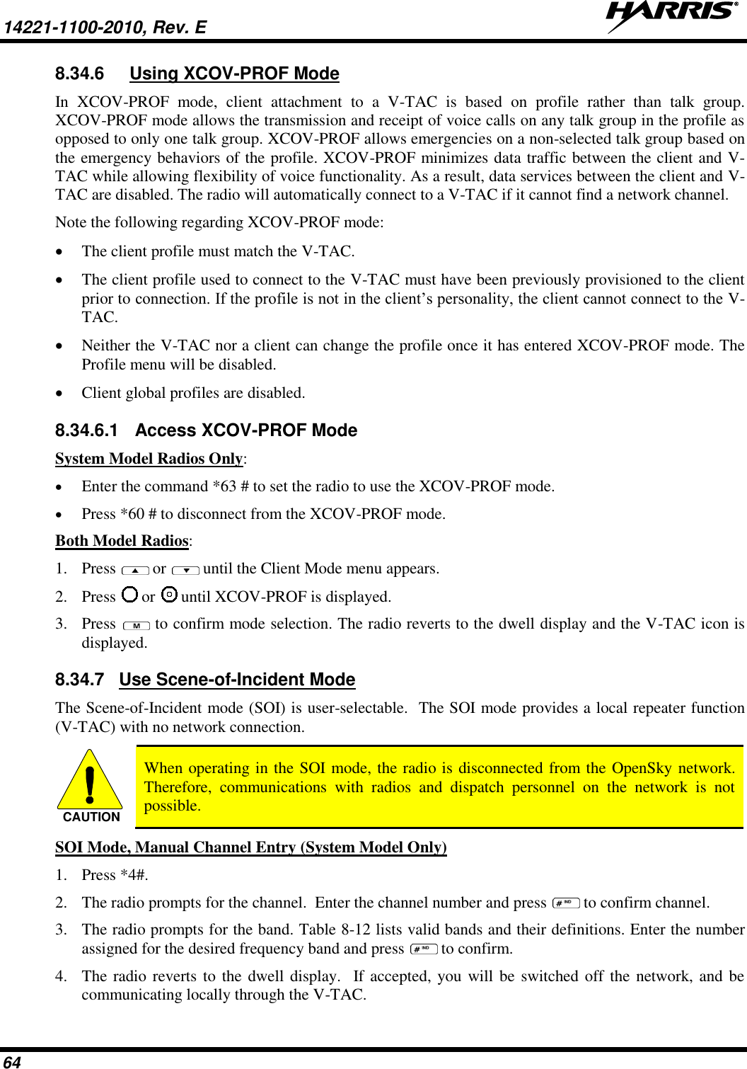
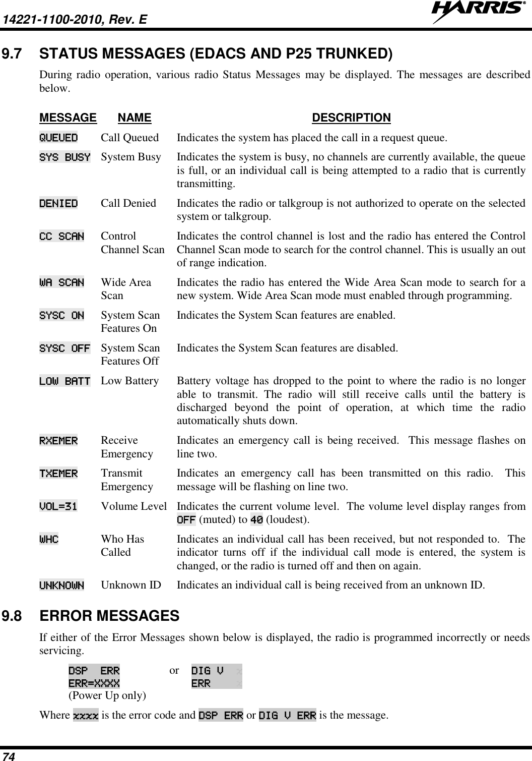
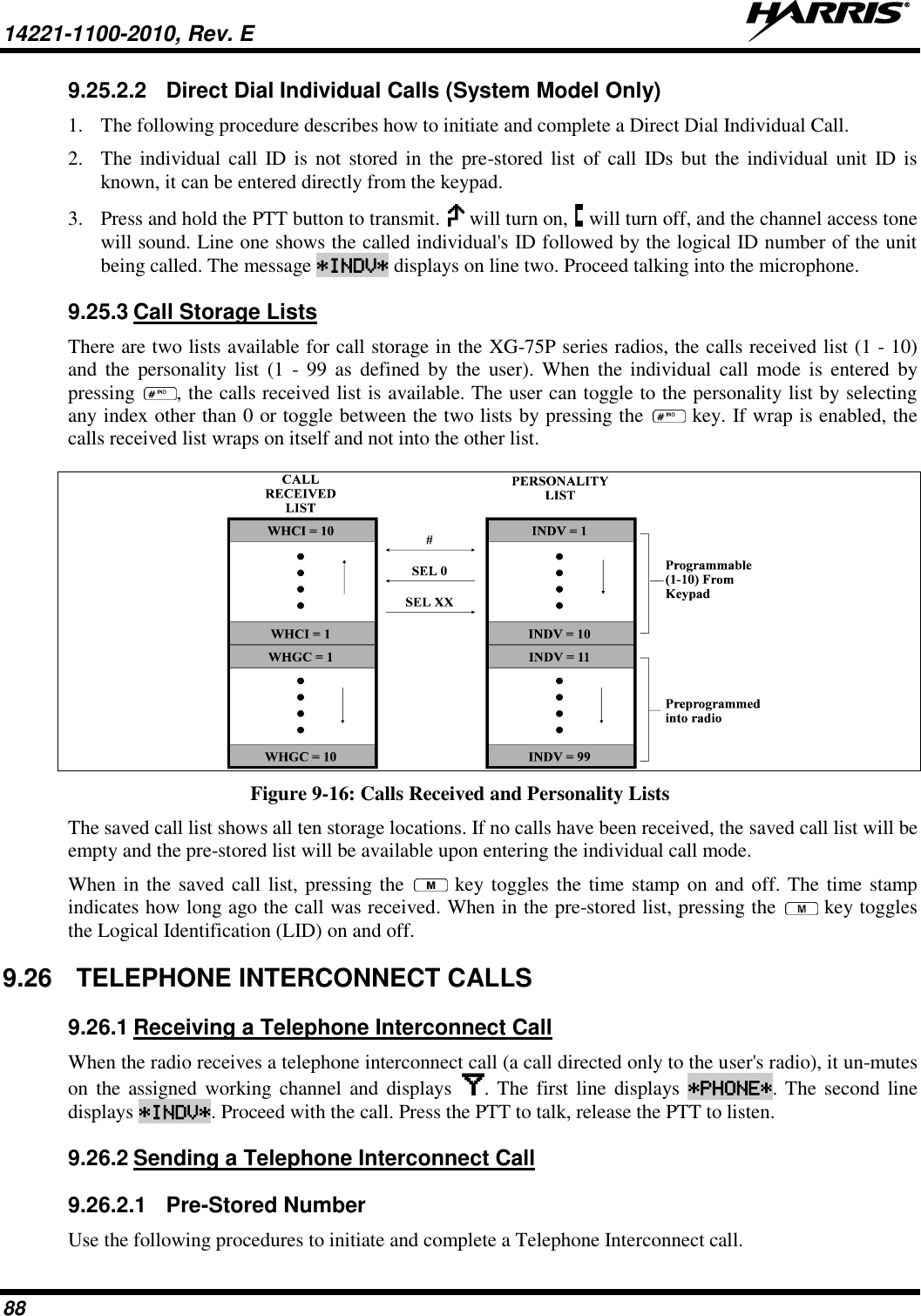
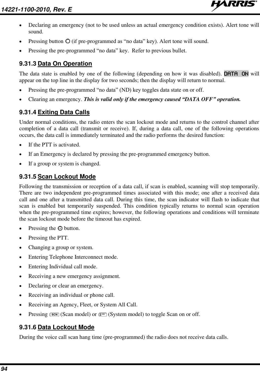
![14221-1100-2010, Rev. E 29 6 OPTIONS AND ACCESSORIES Table 6-1 lists the Options and Accessories tested for use with the XG-75P series portable radios. Refer to the Harris Products and Services Catalog for a complete list of options and accessories, including those items that do not adversely affect the RF energy exposure. Always use Harris authorized accessories (antennas, batteries, belt clips, speaker/mics, etc). Use of unauthorized accessories may cause the FCC Occupational/Controlled Exposure RF compliance requirements to be exceeded. (Refer to Table 1-1.) Always use the correct options and accessories (battery, antenna, speaker/mic, etc.) for the radio. Immersion rated options must be used with an immersion rated radio. Intrinsically safe options (identified by [FM]) are certified by Factory Mutual (FM) and must only be used with FM certified radios. (Refer to Table 6-1.) Table 6-1: Options and Accessories1 DESCRIPTION PART NUMBER OPTION NUMBER ANTENNAS Helical coil (136-151 MHz) [FM] KRE 101 1219/1 EVXG-NC1B Helical coil (150-162 MHz) [FM] KRE 101 1219/2 EVXG-NC1C Helical coil (162-174 MHz) [FM] KRE 101 1219/3 EVXG-NC1D Helical coil (150-174 MHz) [FM] KRE 101 1219/21 EVXG-NC5W Helical stub (378-403 MHz) [FM] KRE 101 1219/9 EVXG-NC5B Helical stub (403-430 MHz) [FM] KRE 101 1219/10 EVXG-NC1U 1/4 - wave whip (378-430 MHz) [FM] KRE 101 1223/10 EVXG-NC1L Helical stub (430-470 MHz) [FM] KRE 101 1219/12 EVXG-NC1F Wideband whip (764-870 MHz) [FM] KRE 101 1506/2 MAEV-NNC5X 1/2 - wave (764-870 MHz) [FM] KRE 101 1506/1 MAEV-NNC5K Helical Stub (470-512 MHz) KRE 101 1219/14 MAEV-NNC5Y ¼ Wave Whip (440-512 MHz) KRE 101 1223/12 MAEV-NNC1N Helical Stub (470-512 MHz) KRE 101 1219/13 XXNC1G BATTERIES Nickel Metal Hydride (NiMH) Battery, Immersible BT-023406-003 MAEV-NPA9X NiMh Battery, [FM] BT-023406-004 MAEV-NPA2A Lithium-Ion (Li-Ion) Battery, Immersible BT-023406-005 MAEV-NPA9Y Lithium Polymer, Immersible BT-023436-001 MAEV-PA2U CHARGERS Power Adapter Kit, VC4000 Charger PS-007810-001 MAH2-NPS9X VC4000 Tri-Chemistry Charger CH-017231-001 MAH2-VC4PB Single Charger, Tri-Chemistry CH-104560-007 MAEV-NCH9T 6-bay Charger, Li-Ion/Polymer 12082-0314-01 MAEV-CH4B Wall Mount Kit, 6-Bay Li-Ion/Poly Charger 12082-0315-01 MAEV-AE4A Charger, 6-Bay, Tri-Chemistry CH-104570-007 MAEV-NCH9U AUDIO ACCESSORIES Speaker Mic without Antenna (cc) provision, [FM] MC-023933-001 MAEV-NAE9D Rugged Speaker Mic, Antenna, Straight, SBR [FM] MC-011617-602 MAEV-NAE6D Earphone for Speaker Mic, [FM] LS103239V1 MAEV-NAE3Z Earphone for Speaker Mic, right angle jack LS103239V2 EV-AE1K 1 Options and Accessories table updated in 14221-1100-2010, Rev. E. WARNINGCAUTION](https://usermanual.wiki/HARRIS/TR-0131-E/User-Guide-2394040-Page-30.png)
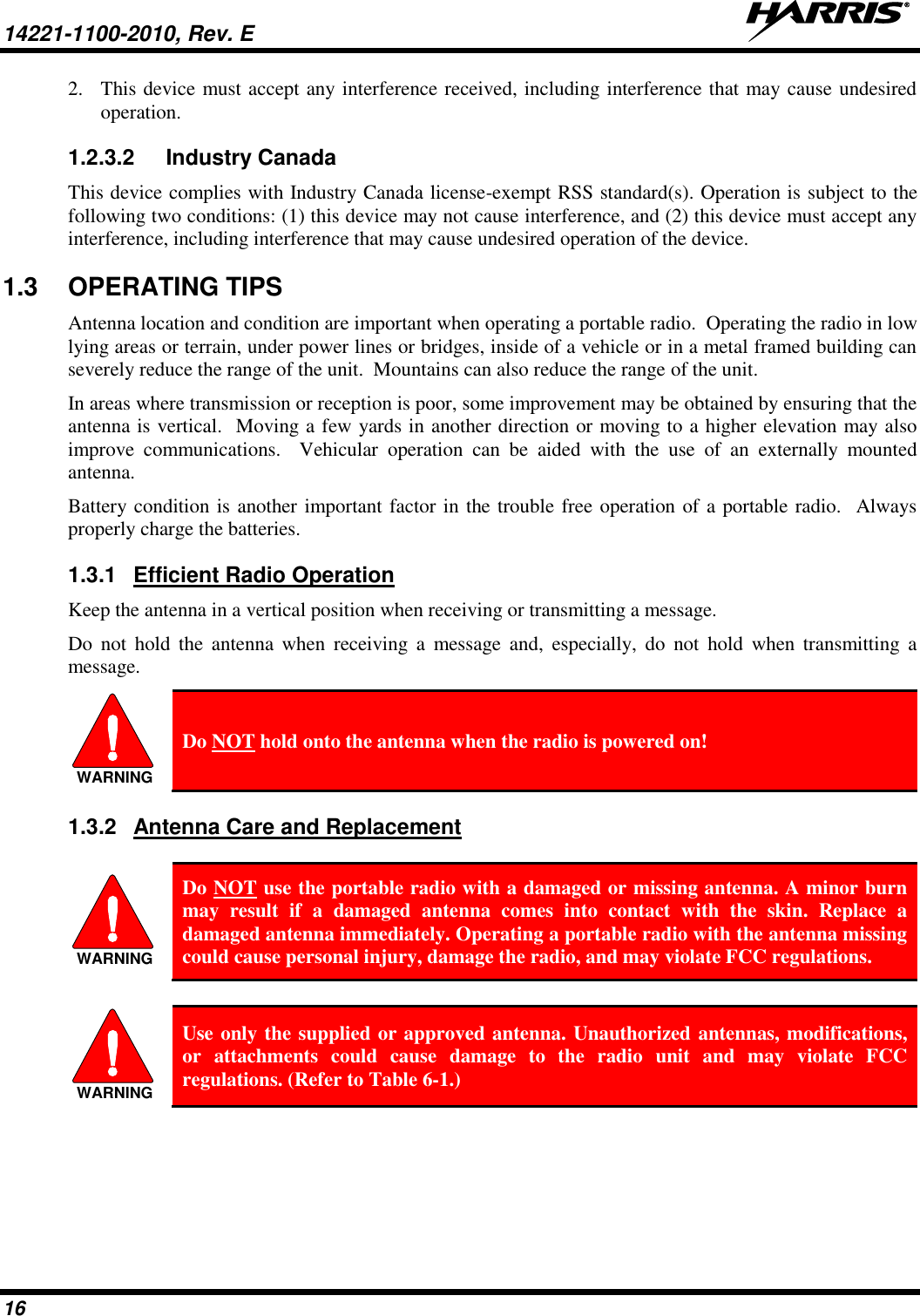
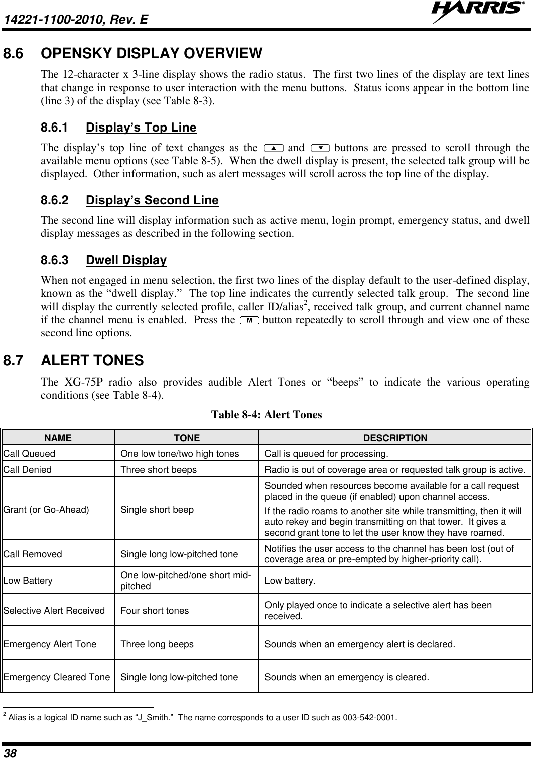
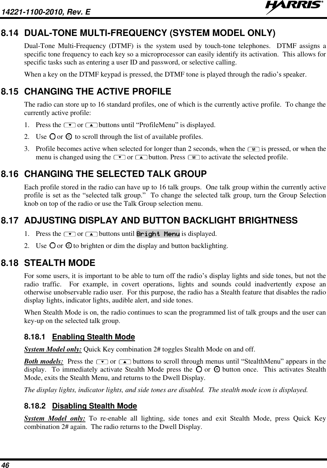
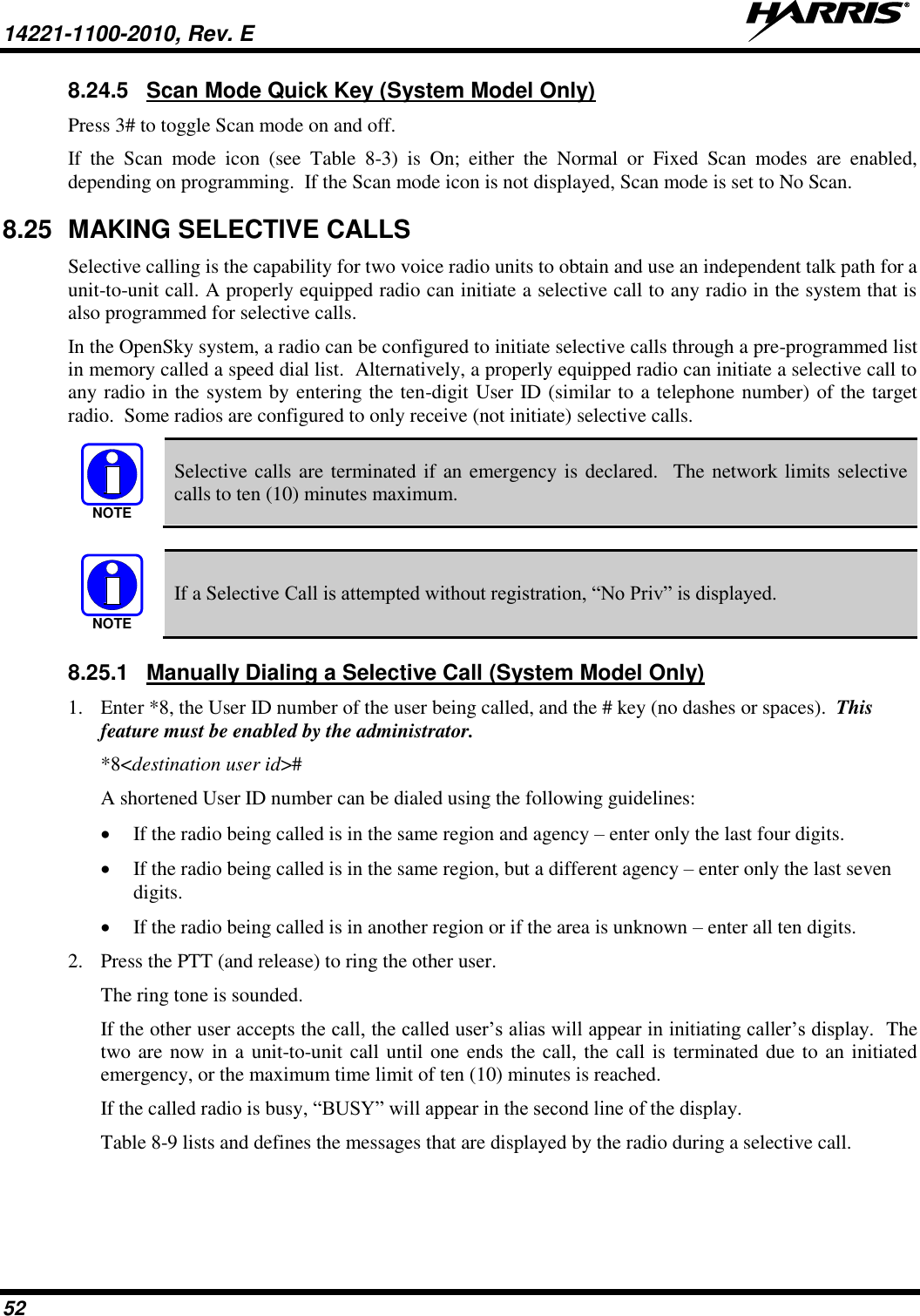
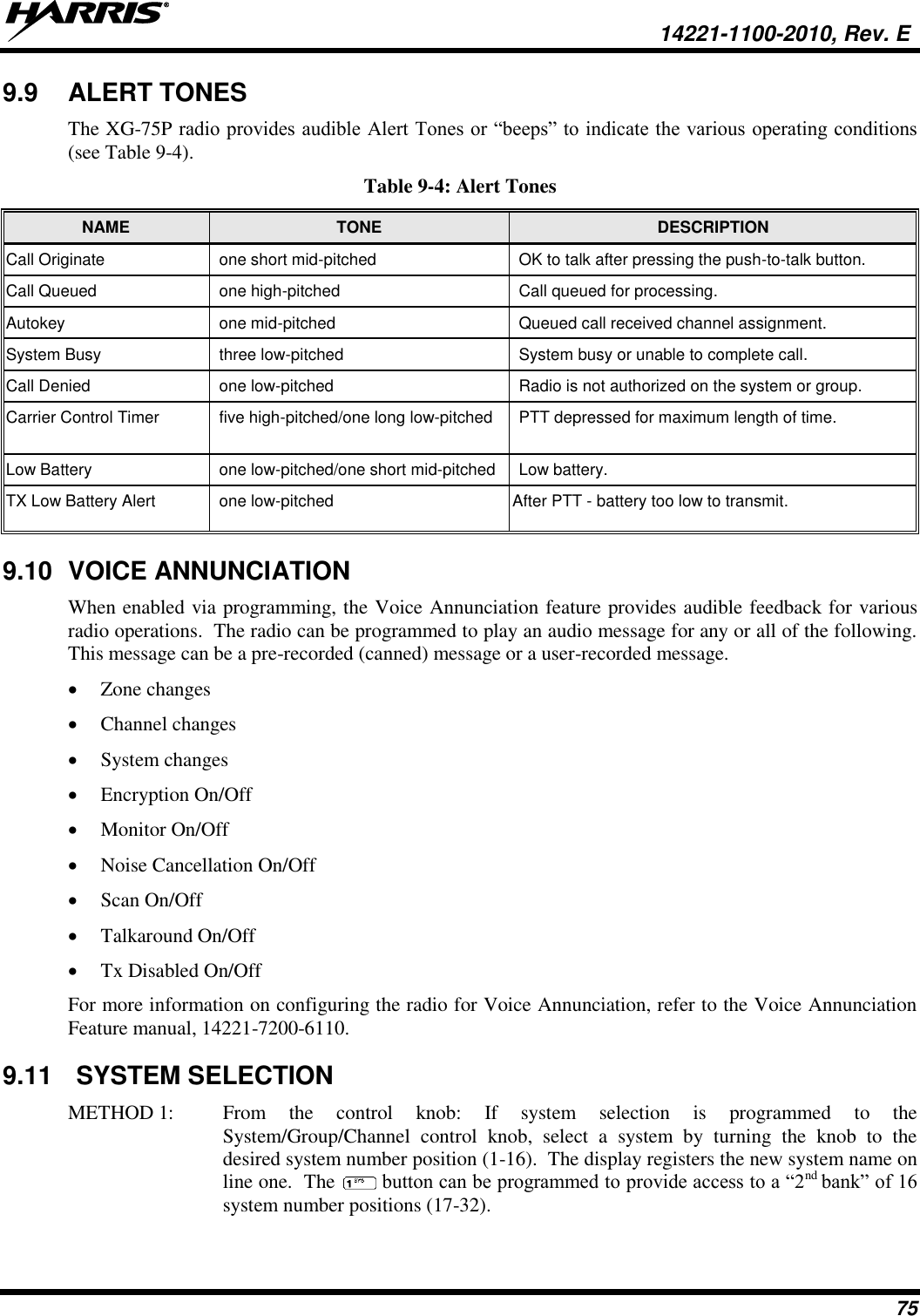
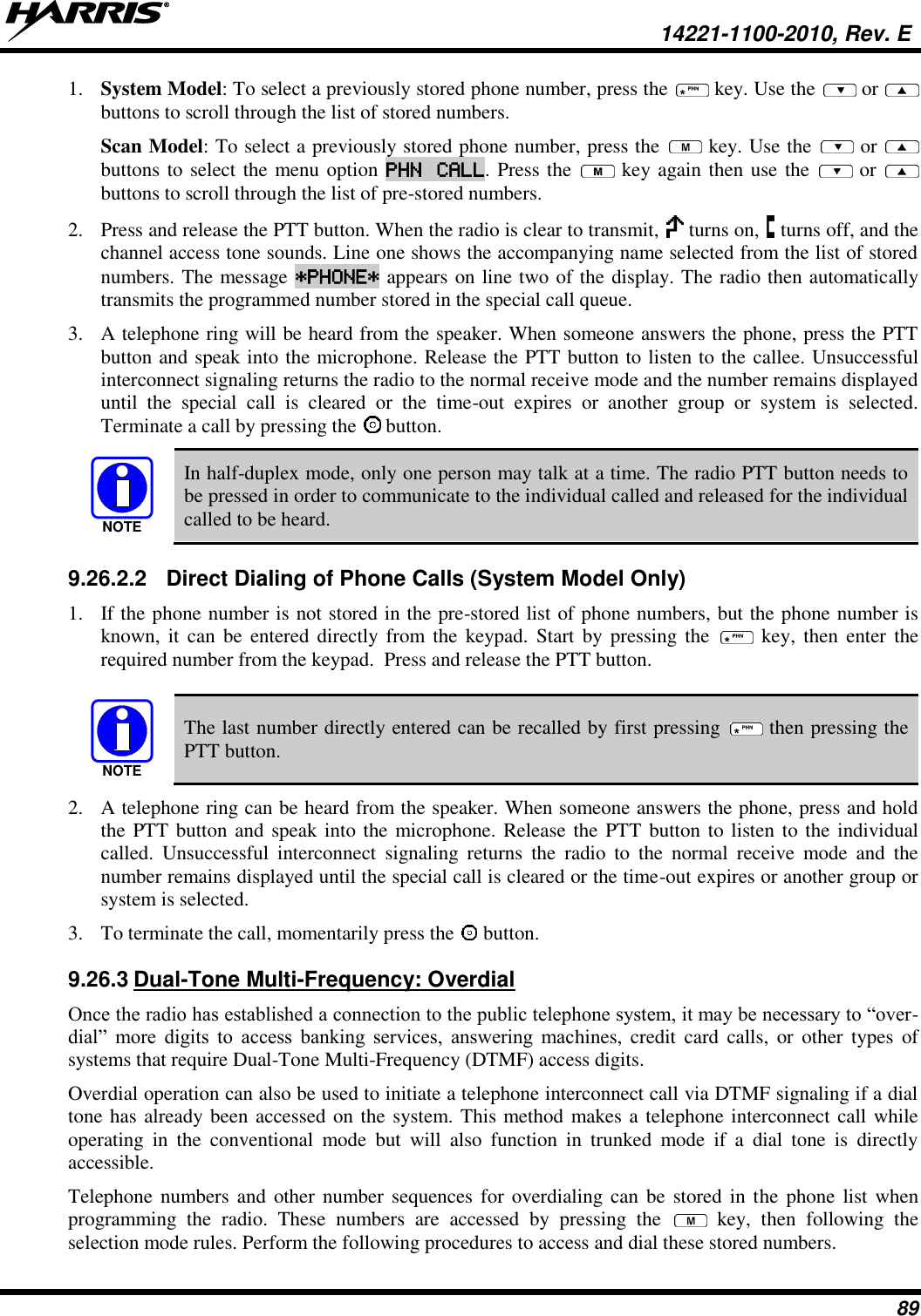
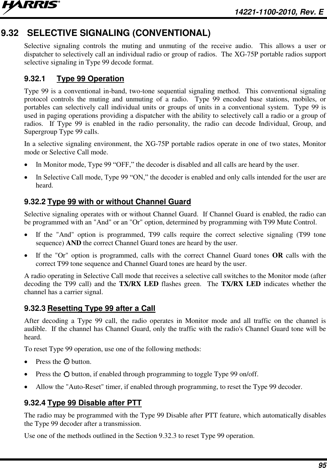
![14221-1100-2010, Rev. E 30 DESCRIPTION PART NUMBER OPTION NUMBER GPS MC-009104-002 MAEV-NAE9R Ruggedized Speaker Mic-Coil Cord [FM] MC-011617-601 MAEV-NAE6C Standard Speaker Mic - Non Ant [FM] MC-011617-701 MAEV-NAE6A Rugged Speaker Mic, Coiled Cord, Hi-Visibility MC-011617-606 EV-AE4C Speaker Mic, Straight Cord, 25.6in, Antenna MC-011617-703 MAEV-AE6L Speaker Mic, Antenna, Straight, 18in MC-011617-718 MAEV-AE6M Speaker Mic, Antenna, Straight, 30in MC-011617-730 MAEV-AE6N Speaker Mic, Rugged, Coiled, Hirose Port MC-011617-611 EV-AE4K DROP SHIP AUDIO ACCESSORIES Earphone Kit, Black EA-009580-001 Earphone Kit, Beige EA-009580-002 2-Wire Kit, Palm Mic, Black EA-009580-003 2-Wire Kit, Palm Mic, Beige EA-009580-004 3-Wire Kit, Mini-Lapel Mic, Black EA-009580-005 3-Wire Kit, Mini-Lapel Mic, Beige EA-009580-006 Explorer Headset with PTT EA-009580-007 Lightweight Headset Single Speaker with PTT EA-009580-008 Breeze Headset with PTT EA-009580-009 Headset, Heavy Duty, N/C Behind-the-Head, with PTT EA-009580-010 Ranger Headset with PTT EA-009580-011 Skull Mic with Body PTT and Earcup EA-009580-012 Headset, Heavy Duty, N/C Over-the-Head, with PTT EA-009580-013 Throat Mic with Acoustic Tube and Body PTT EA-009580-014 Throat Mic with Acoustic Tube, Body PTT, and Ring PTT EA-009580-015 Breeze Headset with PTT and Pigtail Jack EA-009580-016 Hurricane Headset with PTT EA-009580-017 Hurricane Headset with PTT and Pigtail Jack EA-009580-018 CARRYING CASE ACCESSORIES Black Nylon Case with Belt Loop Kit 14011-0012-01 contains: 14011-0011-01 CC-014527 MAEV-NHC2A Orange Nylon Case with Belt Loop Kit 14011-0012-02 contains: 14011-0011-02 CC-014527 MAEV-NHC2B Leather Case with Belt Loop Kit 14011-0012-03 contains: 14011-0011-03 KRY1011608/2 CC-014527 MAEV-NHC2C Leather Case with Shoulder Strap Kit 14011-0012-04 contains: 14011-0011-04 KRY1011608/2 CC-014524-001 MAEV-NHC2D Short Leather Retaining Strap (use with Shoulder Strap application) CC-014524-002 MAEV-NHC2E Metal Belt Clip CC23894 MAEV-NHC2G Strap Holder, “T” KRY 101 1656/1 MAEV-NHC2J Belt Loop, Leather with Swivel KRY1011609/1 FM-017262-001 MAEV-NHC7T](https://usermanual.wiki/HARRIS/TR-0131-E/User-Guide-2394040-Page-31.png)
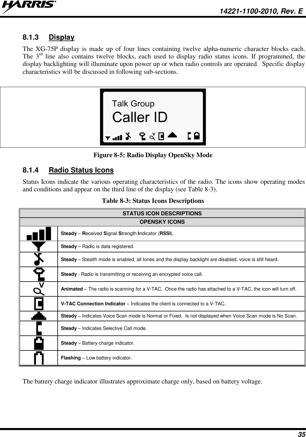
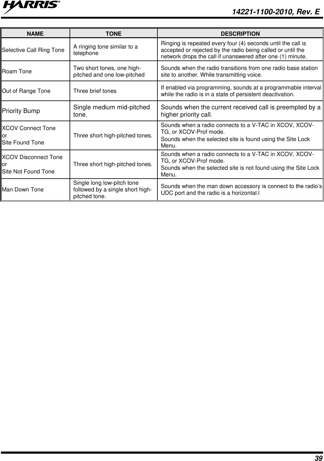
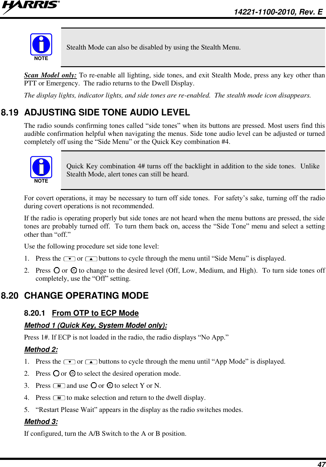
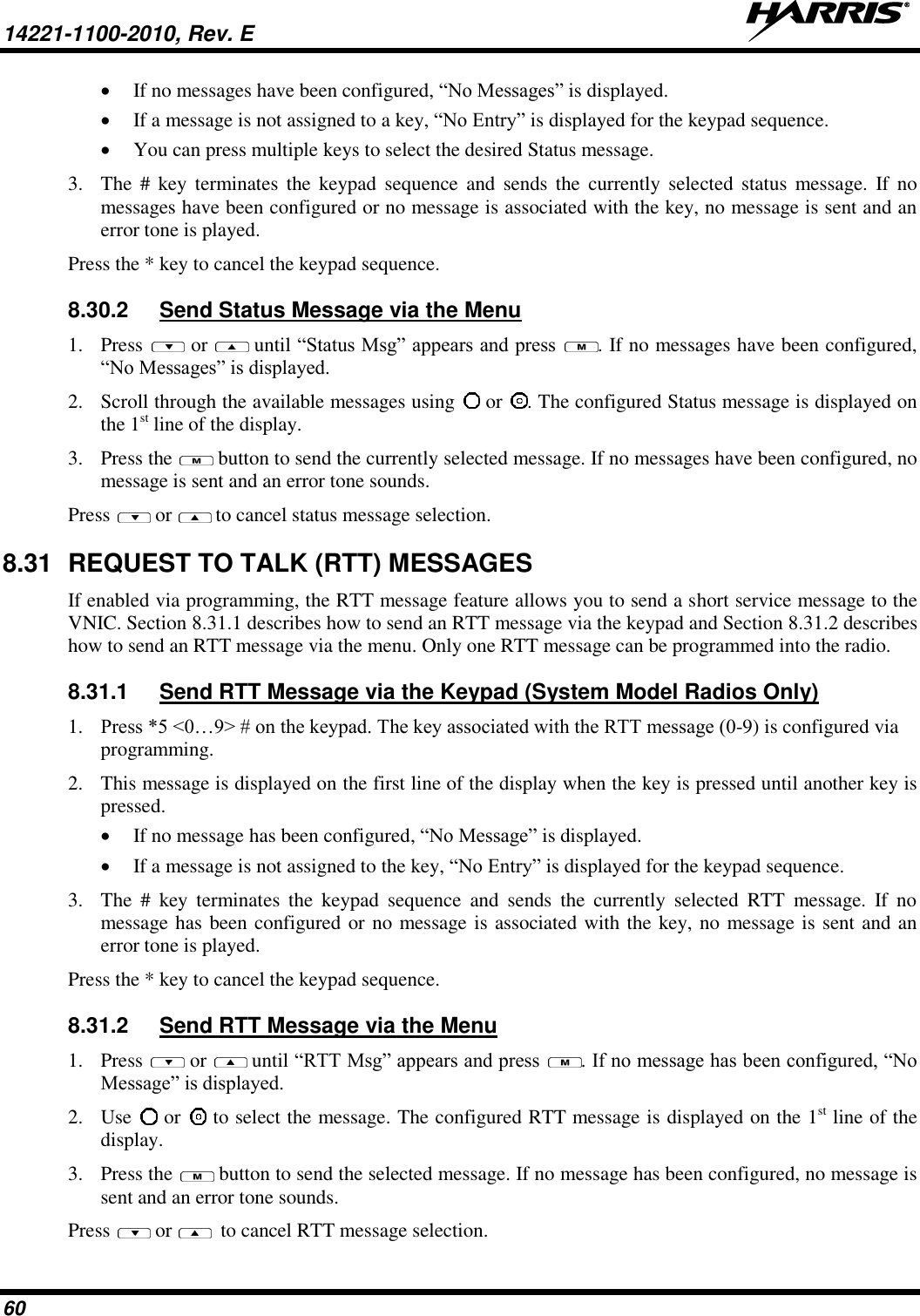
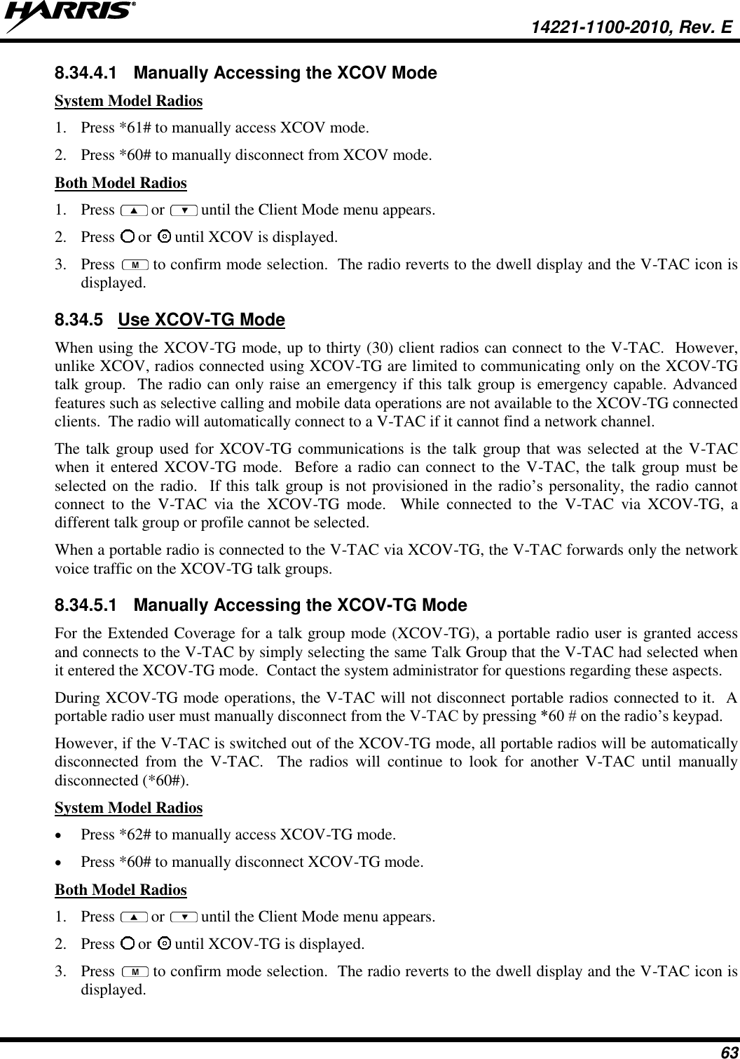
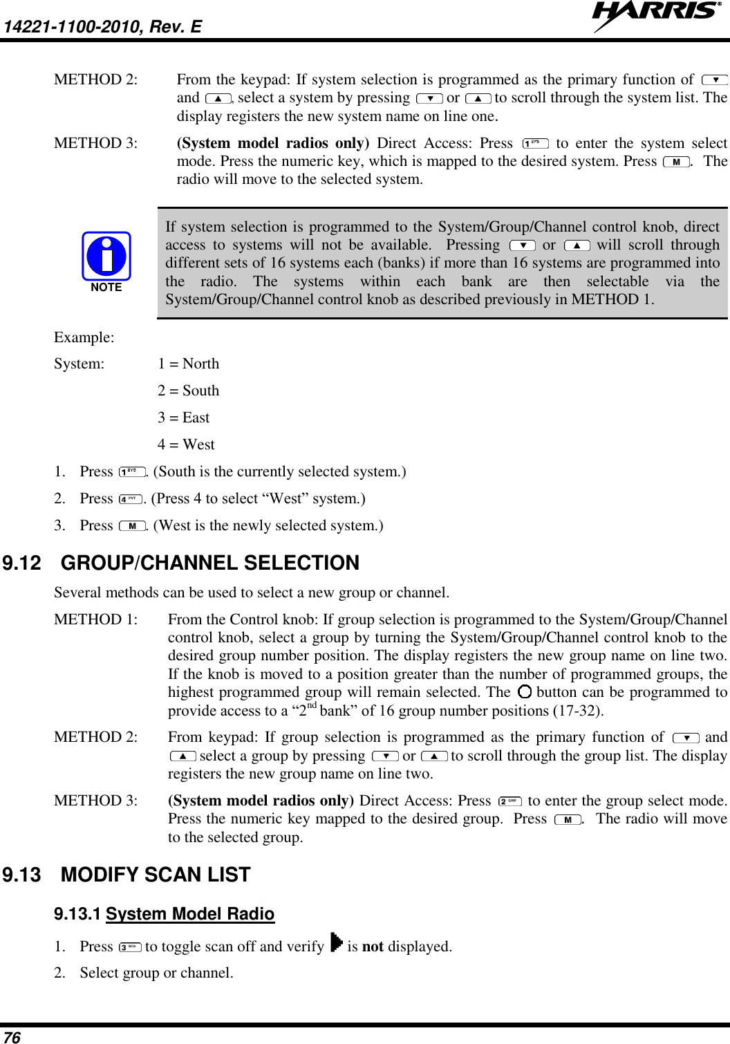
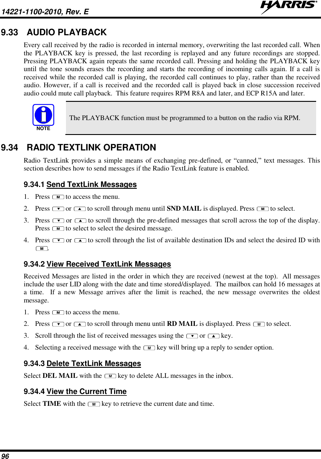
![14221-1100-2010, Rev. E 40 8.8 BASIC MENU STRUCTURE Table 8-5 illustrates the basic XG-75P OpenSky menu structure. Menu items will vary depending upon system programming, radio hardware, and optional configurations. All menus except the dwell display menu can be turned off by network administration personnel. Table 8-5: Basic OpenSky Menu Structure MENU NAME RADIO DISPLAYS USAGE NOTES To/From Dwell Display Engineering Display bit-error rates, RSSI data, sync status, current channel and registration status Displays radio system connection data. For engineering use. Silent Emergency “SilentEmerg” Use or to toggle between OFF/ON. Press to enable. Operating Mode “App Mode” Use or to choose an available mode (OTP, OCF, or ECP). Press and confirm (Y/N) with or and again. GPS Fix “GPS” GPS latitude and longitude position of currently tuned-to base station [“GPS (Site)”] or V-TAC (“GPS”) scrolls across top line of the display. “GPS (Aged)” indicates V-TAC coordinates haven’t been updated for more that 2 minutes. User ID “User ID” User’s identification/name scrolls across top line of the display (if programmed). IP Address “IP Address” Radio’s Internet Protocol (IP) address scrolls across top line of the display. Station Identification “Station ID” Station’s identification/name scrolls across top line of the display (if programmed). Stealth Mode (display backlight is disabled) “StealthMenu” Use or to turn Stealth Mode “On” or “Off.” See Section 8.17 for more information about Stealth Mode. Treble Level “Treble Menu” Use or to choose speaker treble level (LOW, MEDIUM, MEDHIGH, or HIGH). Press to return to dwell display. Display Brightness “Bright Menu” Use or to brighten or dim backlighting. Press to return to dwell display. Side Tone Level “Side Menu” Use or to choose side tone level (OFF, LOW, MED, or HIGH). Press to return to dwell display. See Next Page](https://usermanual.wiki/HARRIS/TR-0131-E/User-Guide-2394040-Page-41.png)
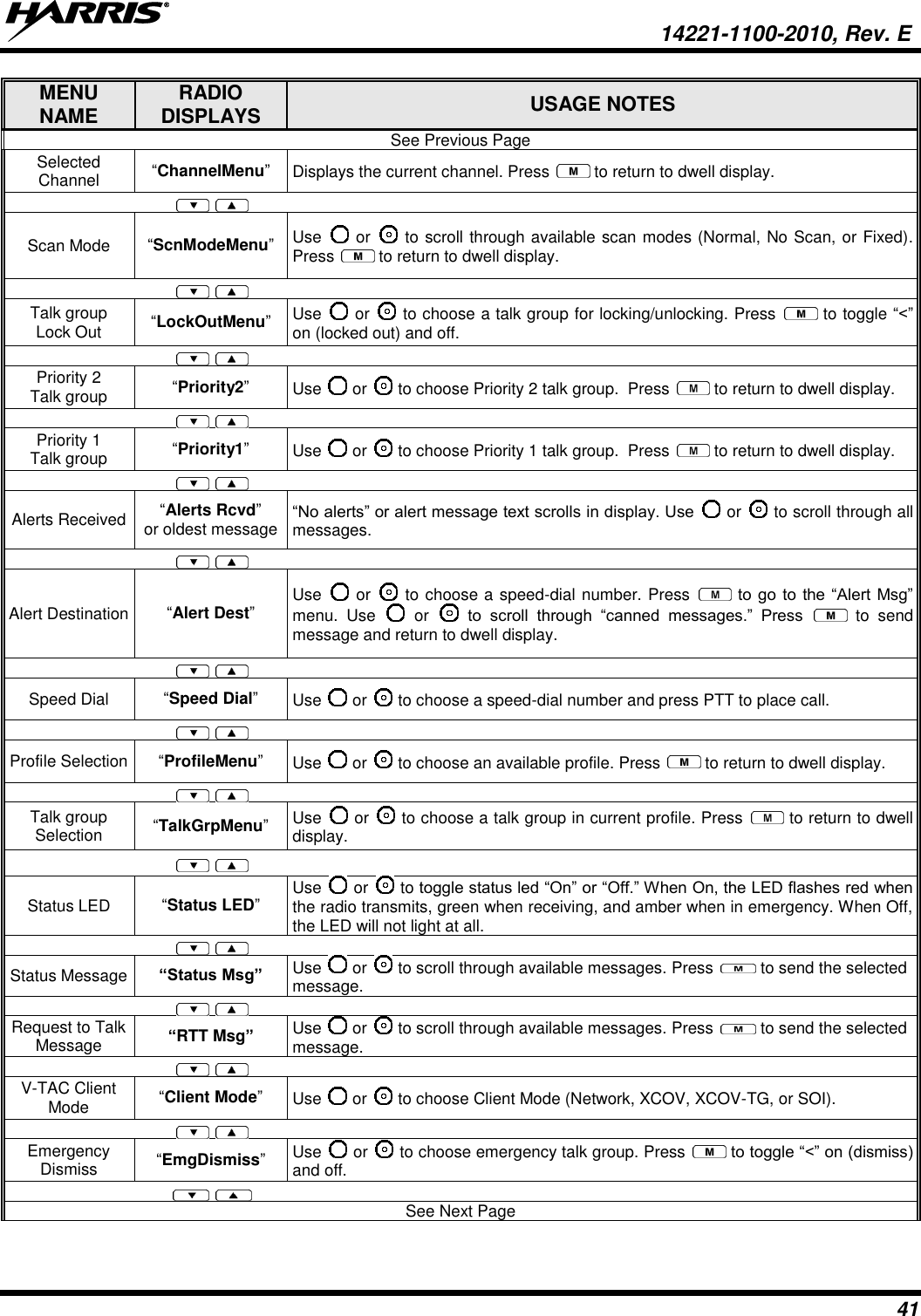
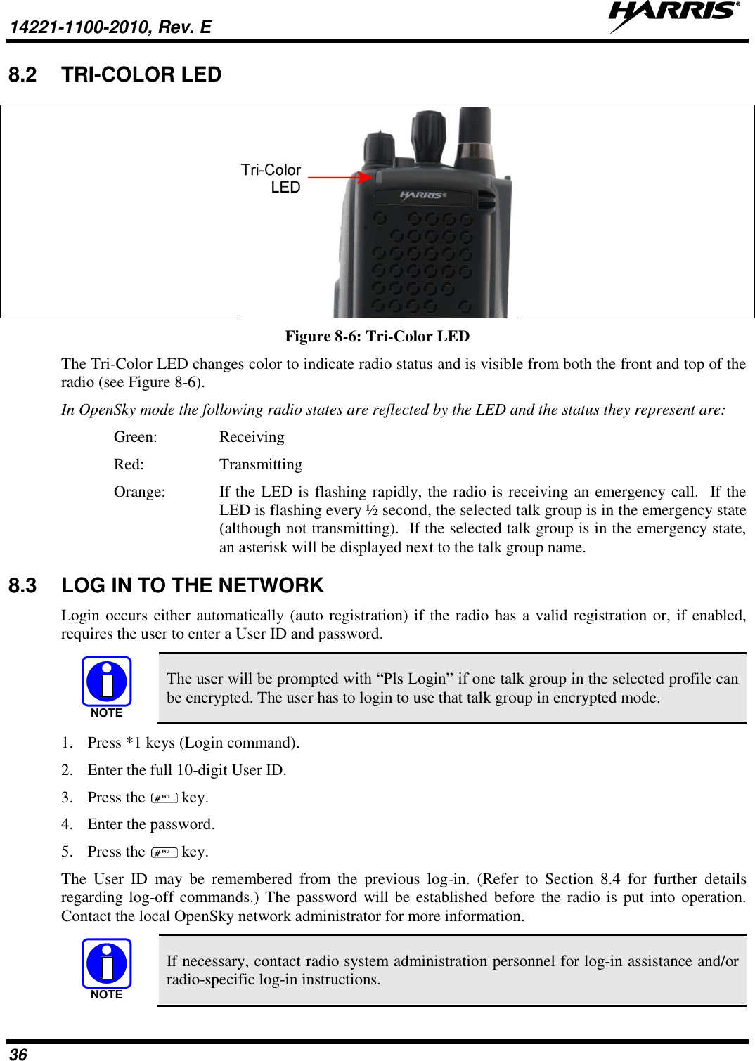
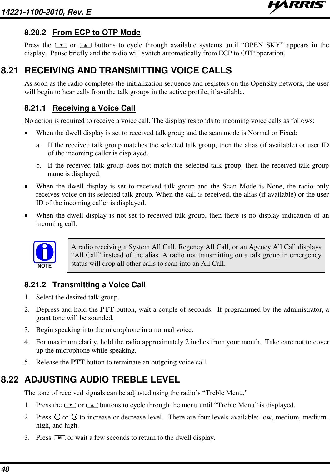
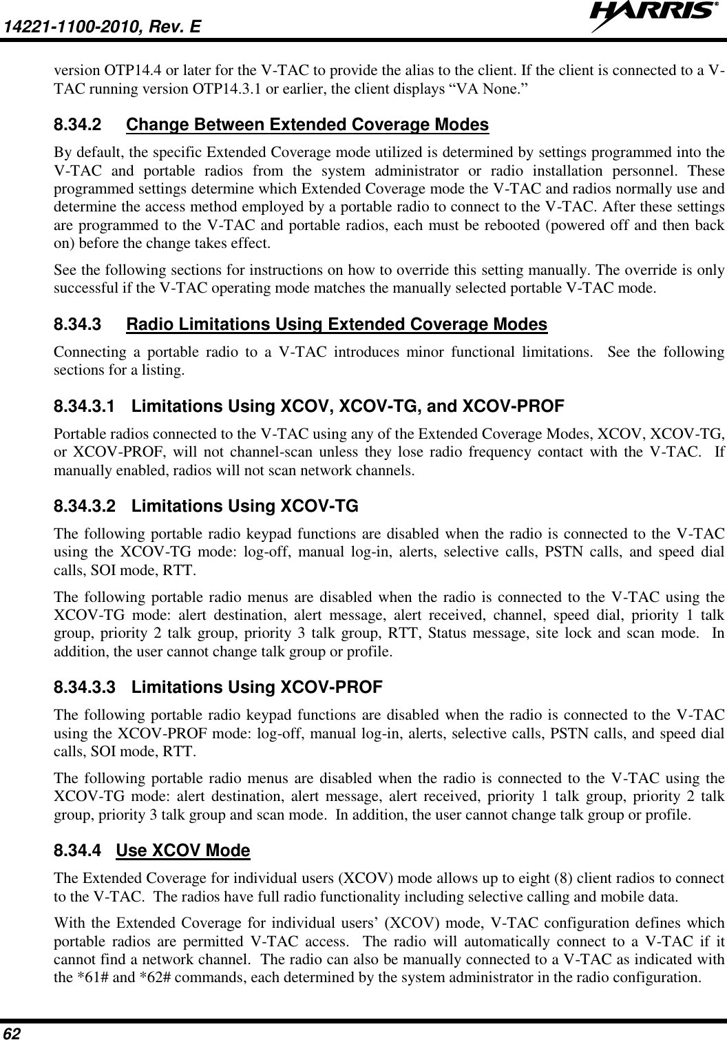
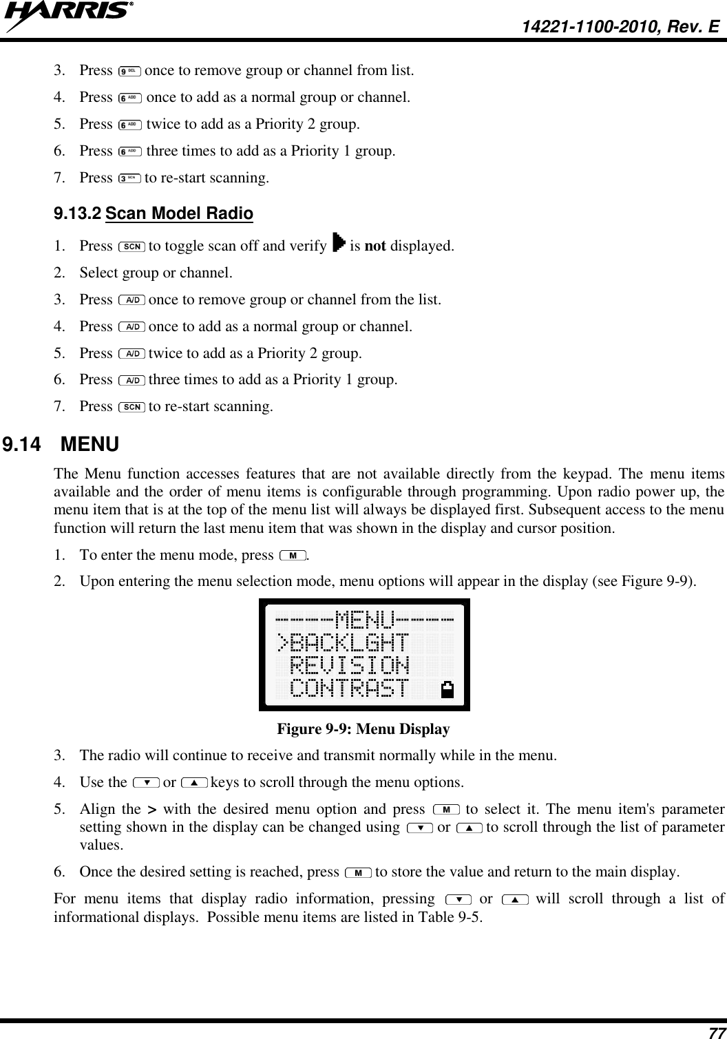
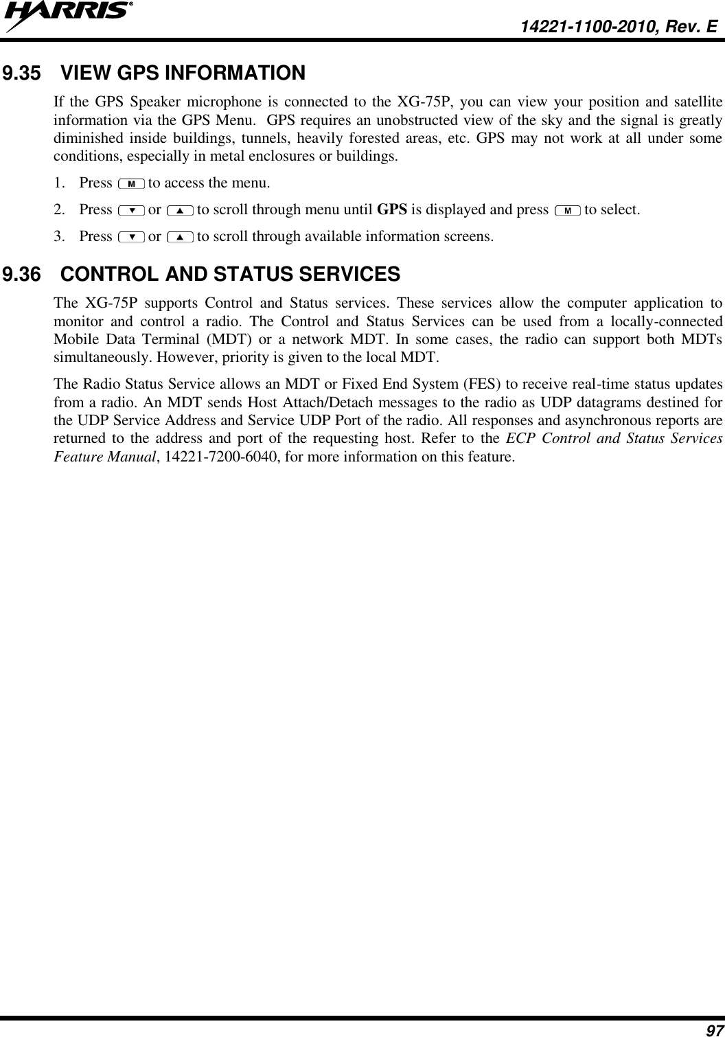
![14221-1100-2010, Rev. E 44 MESSAGE DESCRIPTION NO REG Not registered with MDIS, VNIC, or both. DISABLED Function disabled (e.g., function invalid in current context). 8.10 KEYPAD FUNCTION COMMANDS (SYSTEM MODEL ONLY) To perform a command from the keypad, use the keypad commands in Table 8-6. Table 8-6: Keypad Function Commands COMMANDS FUNCTION *0 Log-off command: *0## (logs the user off the system). See Section 8.4 for additional information. *1 Log-in command: *1<User ID> # <Password> ## (required for encryption). See Section 8.1.3 for additional information. *2 Status Message: *2 <0...9> #. *4 Enter Scene of Incident Mode (SOI) on specified channel and band: *4#<Chan>#<Band># where Chan is the channel number that is being used as a SOI repeater and band is the number assigned to each frequency band. For example, if Channel 25 800 MHz (band 0) is being used for SOI, then enter *4#25#0#. Exit SOI Mode with *40#. *5 RTT Message: *5 <0...9> #. *7 Initiate Selective Alert command: *7<Target ID>#[Choose Message]#. See Section 8.26 for additional information. *8 Radio-to-Radio Call command: *8<Selective call number>#(PTT to dial). *9 Public Switched Telephone Network (PSTN) Call command: *9 <telephone number>#(PTT to dial) See Section 8.27 for additional information. *32 Begin Manual Encryption command: *32<Pre-determined Encryption Key># 1-16 digit encryption key for 128 bit encryption; 17-32 digit encryption key for 256 bit encryption. *33 End Manual Encryption command: *33#. *61 Initiate XCOV Mode: Extended coverage for individual users. *62 Initiate XCOV-TG Mode: Extended coverage for talk groups. *63 Initiate XCOV-PROF Mode command: *63#. *60 Exit XCOV or XCOV-TG Mode: Returns to the Network mode.](https://usermanual.wiki/HARRIS/TR-0131-E/User-Guide-2394040-Page-45.png)
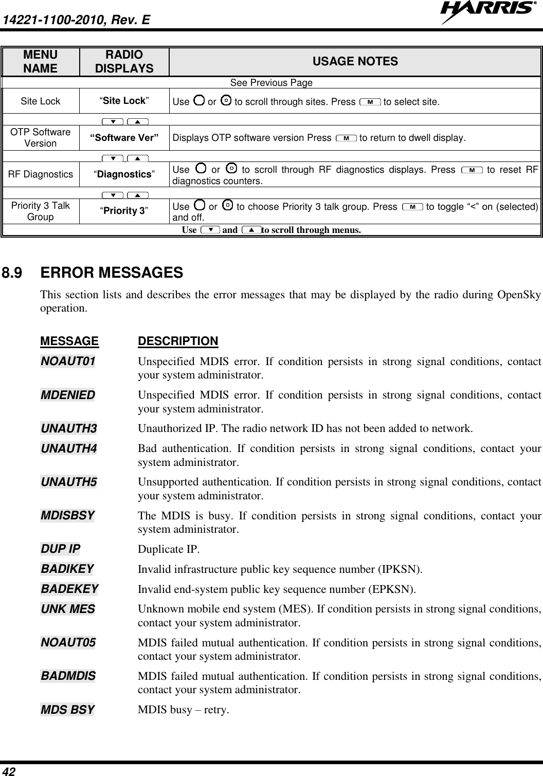
![14221-1100-2010, Rev. E 61 8.32 SITE LOCK Users may need to select the site in cases where network communications are down. The Site Lock menu allows a user to manually roam to a specific site. The sites in the menu are populated with the current site, adjacent sites, and node 2 sites. The menu allows the user to select a particular site based on the Site Name. Once selected, the radio will randomly pick a channel at the site that is identified as operational and attempt to attach to it. If the channel is not available, the radio attempts to attach to the next channel in the channel list for the site until it has attempted every channel at the site. If no channels are available, the radio plays a “Site Not Found” tone and displays “SiteUnavail” on the second line of the Site Lock menu. The radio reverts to its normal roaming functionality. If the radio does find a valid channel on the site, it attaches to it, plays a “Site Found” tone, displays “SiteAvail” on the second line of the Site Lock menu for 2 seconds, and then reverts to the Dwell menu 8.33 GPS COORDINATES The radio’s current latitude and longitude coordinates may be displayed using the “GPS” menu. The following procedure assumes a GPS antenna is connected to the radio and it is receiving adequate signals from GPS satellites. 1. Press or until the “GPS” menu appears in the display. Current GPS coordinate latitude and longitude data continuously scrolls in the top line of the display in a degrees:minutes:seconds format. 2. Press or to change to another menu. If the internal GPS receiver’s data is expired (30 minutes or more) or unavailable, the radio uses the serving base station’s coordinates [GPS (Site) is displayed]. The GPS Menu will also indicate if the data is aged (2 minutes or more) [GPS (Aged) is displayed]. 8.34 V-TAC OPERATION 8.34.1 Extended Coverage Modes (XCOV, XCOV-TG, and XCOV-PROF) In addition to all standard portable radio operating capabilities, Extended Coverage adds the V-TAC’s bridging (vehicular repeat) functionality for accessing the OpenSky radio network. Each portable radio connected to the V-TAC using Extended Coverage is considered a “client” on the V-TAC. Extended Coverage benefits portable radio users since it allows them to get network connectivity using the V-TAC’s higher transmit output power and better antenna system. The V-TAC supports three Extended Coverage modes: Extended Coverage for individual users (XCOV), Extended Coverage for a talk group (XCOV-TG), and Profile Extended Coverage (XCOV-PROF). Typically, Extended Coverage is used after the vehicle’s operator has exited the vehicle with a portable radio unit and the portable unit requires this bridging functionality to access the OpenSky radio network. The V-TAC takes advantage of OpenSky’s TDMA capability to eliminate interference between its local and network radio links when operating in an Extended Coverage mode, an undesirable characteristic of many traditional vehicular repeater systems. Because the V-TAC employs this technology, interference on the network and local radio links is minimized. A V-TAC in Extended Coverage mode sends its alias to clients. The alias is displayed in the second line of the dwell menu of the client, (“VA <alias>”). The client must be connected to a V-TAC running NOTE](https://usermanual.wiki/HARRIS/TR-0131-E/User-Guide-2394040-Page-62.png)


![14221-1100-2020, Rev. B 5 Česky [Czech] Harris Corporation tímto prohlašuje, že tento XG-75P VHF (136 – 174 MHz) UHF-L (378 – 470 MHz) je ve shodě se základními požadavky a dalšími příslušnými ustanoveními směrnice 1999/5/ES. Dansk [Danish] Undertegnede Harris Corporation erklærer herved, at følgende udstyr XG-75P VHF (136 – 174 MHz) UHF-L (378 – 470 MHz) overholder de væsentlige krav og øvrige relevante krav i direktiv 1999/5/EF. Deutsch [German] Hiermit erklärt Harris Corporation, dass sich das Gerät XG-75P VHF (136 – 174 MHz) UHF-L (378 – 470 MHz) in Übereinstimmung mit den grundlegenden Anforderungen und den übrigen einschlägigen Bestimmungen der Richtlinie 1999/5/EG befindet. Eesti [Estonian] Käesolevaga kinnitab Harris Corporation seadme XG-75P VHF (136 – 174 MHz) UHF-L (378 – 470 MHz) vastavust direktiivi 1999/5/EÜ põhinõuetele ja nimetatud direktiivist tulenevatele teistele asjakohastele sätetele. English Hereby, Harris Corporation, declares that this XG-75P VHF (136 – 174 MHz) UHF-L (378 – 470 MHz) is in compliance with the essential requirements and other relevant provisions of Directive 1999/5/EC. Español [Spanish] Por medio de la presente Harris Corporation declara que el XG-75P VHF (136 – 174 MHz) UHF-L (378 – 470 MHz) cumple con los requisitos esenciales y cualesquiera otras disposiciones aplicables o exigibles de la Directiva 1999/5/CE. Ελληνική [Greek] ΜΕ ΤΗΝ ΠΑΡΟΥΣΑ Harris Corporation ΔΗΛΩΝΕΙ ΟΤΙ XG-75P VHF (136 – 174 MHz) UHF-L (378 – 470 MHz) ΣΥΜΜΟΡΦΩΝΕΤΑΙ ΠΡΟΣ ΤΙΣ ΟΥΣΙΩΔΕΙΣ ΑΠΑΙΤΗΣΕΙΣ ΚΑΙ ΤΙΣ ΛΟΙΠΕΣ ΣΧΕΤΙΚΕΣ ΔΙΑΤΑΞΕΙΣ ΤΗΣ ΟΔΗΓΙΑΣ 1999/5/ΕΚ. Français [French] Par la présente Harris Corporation déclare que l'appareil XG-75P VHF (136 – 174 MHz) UHF-L (378 – 470 MHz) est conforme aux exigences essentielles et aux autres dispositions pertinentes de la directive 1999/5/CE. Italiano [Italian] Con la presente Harris Corporation dichiara che questo XG-75P VHF (136 – 174 MHz) UHF-L (378 – 470 MHz) è conforme ai requisiti essenziali ed alle altre disposizioni pertinenti stabilite dalla direttiva 1999/5/CE. Latviski [Latvian] Ar šo Harris Corporation deklarē, ka UHF-L XG-75P (378 – 470 MHz) atbilst Direktīvas 1999/5/EK būtiskajām prasībām un citiem ar to saistītajiem noteikumiem. Lietuvių [Lithuanian] Šiuo Harris Corporation deklaruoja, kad šis XG-75P VHF (136 – 174 MHz) UHF-L (378 – 470 MHz) atitinka esminius reikalavimus ir kitas 1999/5/EB Direktyvos nuostatas.](https://usermanual.wiki/HARRIS/TR-0131-E/User-Guide-2394040-Page-108.png)
![6 14221-1100-2020, Rev. B Nederlands [Dutch] Hierbij verklaart Harris Corporation dat het toestel XG-75P VHF (136 – 174 MHz) UHF-L (378 – 470 MHz) in overeenstemming is met de essentiële eisen en de andere relevante bepalingen van richtlijn 1999/5/EG. Malti [Maltese] Hawnhekk, Harris Corporation, jiddikjara li dan XG-75P VHF (136 – 174 MHz) UHF-L (378 – 470 MHz) jikkonforma mal-ħtiġijiet essenzjali u ma provvedimenti oħrajn relevanti li hemm fid-Dirrettiva 1999/5/EC. Magyar [Hungarian] Alulírott, Harris Corporation nyilatkozom, hogy a XG-75P VHF (136 – 174 MHz) UHF-L (378 – 470 MHz) megfelel a vonatkozó alapvetõ követelményeknek és az 1999/5/EC irányelv egyéb elõírásainak. Polski [Polish] Niniejszym Harris Corporation oświadcza, że XG-75P VHF (136 – 174 MHz) UHF-L (378 – 470 MHz) jest zgodny z zasadniczymi wymogami oraz pozostałymi stosownymi postanowieniami Dyrektywy 1999/5/EC. Português [Portuguese] Harris Corporation declara que este XG-75P VHF (136 – 174 MHz) UHF-L (378 – 470 MHz) está conforme com os requisitos essenciais e outras disposições da Directiva 1999/5/CE. Slovensko [Slovenian] Harris Corporation izjavlja, da je ta XG-75P VHF (136 – 174 MHz) UHF-L (378 – 470 MHz) v skladu z bistvenimi zahtevami in ostalimi relevantnimi določili direktive 1999/5/ES. Slovensky [Slovak] Harris Corporation týmto vyhlasuje, že XG-75P VHF (136 – 174 MHz) UHF-L (378 – 470 MHz) spĺňa základné požiadavky a všetky príslušné ustanovenia Smernice 1999/5/ES. Suomi [Finnish] Harris Corporation vakuuttaa täten että XG-75P VHF (136 – 174 MHz) UHF-L (378 – 470 MHz) tyyppinen laite on direktiivin 1999/5/EY oleellisten vaatimusten ja sitä koskevien direktiivin muiden ehtojen mukainen. Svenska [Swedish] Härmed intygar Harris Corporation att denna XG-75P VHF (136 – 174 MHz) UHF-L (378 – 470 MHz) står I överensstämmelse med de väsentliga egenskapskrav och övriga relevanta bestämmelser som framgår av direktiv 1999/5/EG. Íslenska [Icelandic] Hér með lýsir Harris Corporation yfir því að XG-75P VHF (136 – 174 MHz) UHF-L (378 – 470 MHz) er í samræmi við grunnkröfur og aðrar kröfur, sem gerðar eru í tilskipun 1999/5/EC. Norsk [Norwegian] Harris Corporation erklærer herved at utstyret XG-75P VHF (136 – 174 MHz) UHF-L (378 – 470 MHz) er i samsvar med de grunnleggende krav og øvrige relevante krav i direktiv 1999/5/EF.](https://usermanual.wiki/HARRIS/TR-0131-E/User-Guide-2394040-Page-109.png)