HARRIS TR-0131-E XG-75 UHF-H User Manual FCC IC Certification Report
HARRIS CORPORATION XG-75 UHF-H FCC IC Certification Report
HARRIS >
User Manual

Rhein Tech Laboratories, Inc. Client: Harris Corporation
360 Herndon Parkway Model: XG-75 UHF-H
Suite 1400 IDs: OWDTR-0131-E/3636B-0131
Herndon, VA 20170 Standards: FCC Pt 80/90/22/IC RSS-119
http://www.rheintech.com Report #: 2014082
89 of 113
Appendix N: Manuals
Please refer to the following pages for the Operator’s Manual and the Safety Manual.
Operator’s Manual
14221-1100-2010
Rev. E, Sep/14
XG-75P/XG-75Pe Series
Portable Radios

14221-1100-2010, Rev. E
2
REV
DATE
REASON FOR REVISION
-
Sep/11
Initial release.
A
Nov/11
Updated Table 1-2.
B
Jul/12
Added OpenSky operation.
C
May/13
Added stealth mode and PIN entry (ECP R16A), Audio Playback. Included OTP R20A features. Updates to
OpenSky operation. Updated options and accessories table. Updated warranty.
D
Sep/13
Updated options and accessories table. Updated cleaning procedure.
E
Sep/14
Added Radio TextLink, View GPS, Control and Status Services, CE information, UHF-H band splits to Table 1-1,
A/B/C switch, & Voice Annunciation. Updated options and accessories and data TX/RX indication.
Harris Corporation, Public Safety and Professional Communications (PSPC) Business continually evaluates its technical publications for
completeness, technical accuracy, and organization. You can assist in this process by submitting your comments and suggestions to the
following:
Harris Corporation
PSPC Business fax your comments to: 1-434-455-6851
Technical Publications or
221 Jefferson Ridge Parkway e-mail us at: PSPC_techpubs@harris.com
Lynchburg, VA 24501
ACKNOWLEDGEMENTS
The software contained in this device is copyrighted by Harris Corporation Unpublished rights are reserved under the copyright laws of the
United States.
This device is made under license under one or more of the following US patents: 4,590,473; 4,636,791; 5,148,482; 5,185,796; 5,271,017;
5,377,229; 4,716,407; 4,972,460; 5,502,767; 5,146,497; 5,164,986; 5,185,795; 5,226,084; 5,247,579; 5,491,772; 5,517,511; 5,630,011;
5,649,050; 5,701,390; 5,715,365; 5,754,974; 5,826,222; 5,870,405; 6,161,089; and 6,199,037 B1. DVSI claims certain rights, including
patent rights under aforementioned U.S. patents, and under other U.S. and foreign patents and patents pending. Any use of this software or
technology requires a separate written license from DVSI.
CREDITS
Harris, assuredcommunications, OpenSky, and EDACS are registered trademarks and ProScan and Failsoft are trademarks of Harris
Corporation.
RBRC and 1-800-8-BATTERY are registered trademarks of Rechargeable Battery Recycling Corporation.
AMBE is a registered trademark and IMBE, AMBE+, and AMBE+2 are trademarks of Digital Voice Systems, Inc.
All other product and brand names are trademarks, registered trademarks, or service marks of their respective holders.
NOTICE!
The material contained herein is subject to U.S. export approval. No export or re-export is permitted without written approval from the U.S.
Government. Rated: EAR99; in accordance with U.S. Dept. of Commerce regulations 15CFR774, Export Administration Regulations.
Information and descriptions contained herein are the property of Harris Corporation. Such information and descriptions may not be copied
or reproduced by any means, or disseminated or distributed without the express prior written permission of Harris Corporation, PSPC
Business, 221 Jefferson Ridge Parkway, Lynchburg, VA 24501.
This manual covers Harris Corporation products manufactured and sold by Harris Corporation.
This product conforms to the European Union WEEE Directive 2002/96/EC. Do not dispose of this product in a public
landfill. Take it to a recycling center at the end of its life.
The voice coding technology embodied in this product is protected by intellectual property rights including patent rights, copyrights, and
trade secrets of Digital Voice Systems, Inc. The user of this technology is explicitly prohibited from attempting to decompile, reverse
engineer, or disassemble the Object Code, or in any other way convert the Object Code into human-readable form.
Repairs to this equipment should be made only by an authorized service technician or facility designated by the supplier. Any repairs,
alterations, or substitution of recommended parts made by the user to this equipment not approved by the manufacturer could void the
user’s authority to operate the equipment in addition to the manufacturer’s warranty.
This manual is published by Harris Corporation without any warranty. Improvements and changes to this manual necessitated by
typographical errors, inaccuracies of current information, or improvements to programs and/or equipment, may be made by Harris
Corporation at any time and without notice. Such changes will be incorporated into new editions of this manual. No part of this manual
may be reproduced or transmitted in any form or by any means, electronic or mechanical, including photocopying and recording, for any
purpose, without the express written permission of Harris Corporation.
Copyright © 2011 - 2014 Harris Corporation
14221-1100-2010, Rev. E
3
This device is a RF transceiver intended for land mobile radio applications. The device may have use restrictions, which require that the
national authority be contacted for any system licensing requirements, frequency use, allowable power level, etc.
14221-1100-2010, Rev. E
4

14221-1100-2010, Rev. E
5
Česky
[Czech]
Harris Corporation tímto prohlašuje, že tento XG-75P VHF (136 – 174 MHz) UHF-L (378 – 470 MHz) je ve
shodě se základními požadavky a dalšími příslušnými ustanoveními směrnice 1999/5/ES.
Dansk
[Danish]
Undertegnede Harris Corporation erklærer herved, at følgende udstyr XG-75P VHF (136 – 174 MHz)
UHF-L (378 – 470 MHz) overholder de væsentlige krav og øvrige relevante krav i direktiv 1999/5/EF.
Deutsch
[German]
Hiermit erklärt Harris Corporation, dass sich das Gerät XG-75P VHF (136 – 174 MHz) UHF-L (378 – 470
MHz) in Übereinstimmung mit den grundlegenden Anforderungen und den übrigen einschlägigen
Bestimmungen der Richtlinie 1999/5/EG befindet.
Eesti
[Estonian]
Käesolevaga kinnitab Harris Corporation seadme XG-75P VHF (136 – 174 MHz) UHF-L (378 – 470 MHz)
vastavust direktiivi 1999/5/EÜ põhinõuetele ja nimetatud direktiivist tulenevatele teistele asjakohastele
sätetele.
English
Hereby, Harris Corporation, declares that this XG-75P VHF (136 – 174 MHz) UHF-L (378 – 470 MHz) is in
compliance with the essential requirements and other relevant provisions of Directive 1999/5/EC.
Español
[Spanish]
Por medio de la presente Harris Corporation declara que el XG-75P VHF (136 – 174 MHz) UHF-L (378 –
470 MHz) cumple con los requisitos esenciales y cualesquiera otras disposiciones aplicables o exigibles
de la Directiva 1999/5/CE.
Ελληνική
[Greek]
ΜΕ ΤΗΝ ΠΑΡΟΥΣΑ Harris Corporation ΔΗΛΩΝΕΙ ΟΤΙ XG-75P VHF (136 – 174 MHz) UHF-L (378 – 470
MHz) ΣΥΜΜΟΡΦΩΝΕΤΑΙ ΠΡΟΣ ΤΙΣ ΟΥΣΙΩΔΕΙΣ ΑΠΑΙΤΗΣΕΙΣ ΚΑΙ ΤΙΣ ΛΟΙΠΕΣ ΣΧΕΤΙΚΕΣ ΔΙΑΤΑΞΕΙΣ
ΤΗΣ ΟΔΗΓΙΑΣ 1999/5/ΕΚ.
Français
[French]
Par la présente Harris Corporation déclare que l'appareil XG-75P VHF (136 – 174 MHz) UHF-L (378 – 470
MHz) est conforme aux exigences essentielles et aux autres dispositions pertinentes de la directive
1999/5/CE.
Italiano
[Italian]
Con la presente Harris Corporation dichiara che questo XG-75P VHF (136 – 174 MHz) UHF-L (378 – 470
MHz) è conforme ai requisiti essenziali ed alle altre disposizioni pertinenti stabilite dalla direttiva
1999/5/CE.
Latviski
[Latvian]
Ar šo Harris Corporation deklarē, ka UHF-L XG-75P (378 – 470 MHz) atbilst Direktīvas 1999/5/EK
būtiskajām prasībām un citiem ar to saistītajiem noteikumiem.
Lietuvių
[Lithuanian]
Šiuo Harris Corporation deklaruoja, kad šis XG-75P VHF (136 – 174 MHz) UHF-L (378 – 470 MHz)
atitinka esminius reikalavimus ir kitas 1999/5/EB Direktyvos nuostatas.
Nederlands
[Dutch]
Hierbij verklaart Harris Corporation dat het toestel XG-75P VHF (136 – 174 MHz) UHF-L (378 – 470 MHz)
in overeenstemming is met de essentiële eisen en de andere relevante bepalingen van richtlijn
1999/5/EG.
Malti
[Maltese]
Hawnhekk, Harris Corporation, jiddikjara li dan XG-75P VHF (136 – 174 MHz) UHF-L (378 – 470 MHz)
jikkonforma mal-ħtiġijiet essenzjali u ma provvedimenti oħrajn relevanti li hemm fid-Dirrettiva 1999/5/EC.
Magyar
[Hungarian]
Alulírott, Harris Corporation nyilatkozom, hogy a XG-75P VHF (136 – 174 MHz) UHF-L (378 – 470 MHz)
megfelel a vonatkozó alapvetõ követelményeknek és az 1999/5/EC irányelv egyéb elõírásainak.
Polski
[Polish]
Niniejszym Harris Corporation oświadcza, że XG-75P VHF (136 – 174 MHz) UHF-L (378 – 470 MHz) jest
zgodny z zasadniczymi wymogami oraz pozostałymi stosownymi postanowieniami Dyrektywy 1999/5/EC.
Português
[Portuguese]
Harris Corporation declara que este XG-75P VHF (136 – 174 MHz) UHF-L (378 – 470 MHz) está
conforme com os requisitos essenciais e outras disposições da Directiva 1999/5/CE.

14221-1100-2010, Rev. E
6
Slovensko
[Slovenian]
Harris Corporation izjavlja, da je ta XG-75P VHF (136 – 174 MHz) UHF-L (378 – 470 MHz) v skladu z
bistvenimi zahtevami in ostalimi relevantnimi določili direktive 1999/5/ES.
Slovensky
[Slovak]
Harris Corporation týmto vyhlasuje, že XG-75P VHF (136 – 174 MHz) UHF-L (378 – 470 MHz) spĺňa
základné požiadavky a všetky príslušné ustanovenia Smernice 1999/5/ES.
Suomi
[Finnish]
Harris Corporation vakuuttaa täten että XG-75P VHF (136 – 174 MHz) UHF-L (378 – 470 MHz) tyyppinen
laite on direktiivin 1999/5/EY oleellisten vaatimusten ja sitä koskevien direktiivin muiden ehtojen mukainen.
Svenska
[Swedish]
Härmed intygar Harris Corporation att denna XG-75P VHF (136 – 174 MHz) UHF-L (378 – 470 MHz) står I
överensstämmelse med de väsentliga egenskapskrav och övriga relevanta bestämmelser som framgår av
direktiv 1999/5/EG.
Íslenska
[Icelandic]
Hér með lýsir Harris Corporation yfir því að XG-75P VHF (136 – 174 MHz) UHF-L (378 – 470 MHz) er í
samræmi við grunnkröfur og aðrar kröfur, sem gerðar eru í tilskipun 1999/5/EC.
Norsk
[Norwegian]
Harris Corporation erklærer herved at utstyret XG-75P VHF (136 – 174 MHz) UHF-L (378 – 470 MHz) er i
samsvar med de grunnleggende krav og øvrige relevante krav i direktiv 1999/5/EF.

14221-1100-2010, Rev. E
7
TABLE OF CONTENTS Page
1 REGULATORY AND SAFETY INFORMATION ........................................................................... 13
1.1 SAFETY CONVENTIONS ........................................................................................................ 13
1.2 SAFETY TRAINING INFORMATION .................................................................................... 14
1.2.1 RF Exposure Guidelines ................................................................................................ 14
1.2.2 Electromagnetic Interference/Compatibility.................................................................. 15
1.2.3 Radio Frequency Interference ........................................................................................ 15
1.3 OPERATING TIPS .................................................................................................................... 16
1.3.1 Efficient Radio Operation .............................................................................................. 16
1.3.2 Antenna Care and Replacement ..................................................................................... 16
1.3.3 Electronic Devices ......................................................................................................... 17
1.3.4 Aircraft........................................................................................................................... 17
1.3.5 Electric Blasting Caps ................................................................................................... 17
1.3.6 Potentially Explosive Atmospheres ............................................................................... 17
2 RENSEIGNEMENTS SUR LA RÉGLEMENTATION ET SÉCURITÉ ....................................... 18
2.1 CONVENTIONS SUR LES SYMBOLES DE SÉCURITÉ ...................................................... 18
2.2 RENSEIGNEMENTS SUR LA FORMATION SUR LA SÉCURITÉ ...................................... 18
2.2.1 Directives sur l’exposition aux RF ................................................................................ 19
2.2.2 Interférence/Compatibilité Électromagnétique .............................................................. 20
2.3 INTERFÉRENCE DES RADIOFRÉQUENCES ....................................................................... 20
2.3.1 Partie 15 de la FCC ........................................................................................................ 20
2.3.2 Industrie Canada ............................................................................................................ 20
2.4 CONSEILS D’UTILISATION ................................................................................................... 20
2.4.1 Utilisation Efficace de la Radio ..................................................................................... 20
3 CLEANING ........................................................................................................................................... 23
4 BATTERIES ......................................................................................................................................... 24
4.1 CONDITIONING BATTERY PACKS ...................................................................................... 24
4.1.1 Conditioning NiMH Battery Packs ................................................................................ 24
4.1.2 Conditioning Li-Ion or Li-Poly packs ........................................................................... 24
4.2 STORING LI-ION BATTERY PACKS..................................................................................... 24
4.3 CHARGING BATTERY PACKS .............................................................................................. 25
4.4 BATTERY PACK USAGE ........................................................................................................ 25
4.5 ADDITIONAL INFORMATION .............................................................................................. 25
4.6 CHANGING THE BATTERY PACK ....................................................................................... 26
4.6.1 Removing the Battery Pack ........................................................................................... 26
4.6.2 Attaching the Battery Pack ............................................................................................ 27
4.7 BATTERY DISPOSAL .............................................................................................................. 27
5 INTRODUCTION ................................................................................................................................ 28
6 OPTIONS AND ACCESSORIES ....................................................................................................... 29
7 CHANGE OPERATING MODE ........................................................................................................ 31
7.1 CHANGE FROM OTP MODE .................................................................................................. 31
7.2 CHANGE TO OTP MODE ........................................................................................................ 31
8 OPENSKY OPERATION .................................................................................................................... 32
8.1 CONTROLS ............................................................................................................................... 32
8.1.1 Buttons, Knobs, and Switch........................................................................................... 33
8.1.2 Keypad ........................................................................................................................... 34
8.1.3 Display ........................................................................................................................... 35
8.1.4 Radio Status Icons ......................................................................................................... 35
8.2 TRI-COLOR LED ...................................................................................................................... 36
8.3 LOG IN TO THE NETWORK ................................................................................................... 36

14221-1100-2010, Rev. E
8
TABLE OF CONTENTS Page
8.4 LOG OFF THE NETWORK ...................................................................................................... 37
8.5 PERSONALITY ......................................................................................................................... 37
8.5.1 Profiles ........................................................................................................................... 37
8.5.2 Talk Groups ................................................................................................................... 37
8.6 OPENSKY DISPLAY OVERVIEW .......................................................................................... 38
8.6.1 Display’s Top Line ........................................................................................................ 38
8.6.2 Display’s Second Line ................................................................................................... 38
8.6.3 Dwell Display ................................................................................................................ 38
8.7 ALERT TONES.......................................................................................................................... 38
8.8 BASIC MENU STRUCTURE.................................................................................................... 40
8.9 ERROR MESSAGES ................................................................................................................. 42
8.10 KEYPAD FUNCTION COMMANDS (SYSTEM MODEL ONLY) ........................................ 44
8.11 QUICK KEYS (SYSTEM MODEL ONLY) .............................................................................. 45
8.12 DTMF OVERDIAL .................................................................................................................... 45
8.13 LOCK/UNLOCK THE KEYPAD .............................................................................................. 45
8.14 DUAL-TONE MULTI-FREQUENCY (SYSTEM MODEL ONLY) ........................................ 46
8.15 CHANGING THE ACTIVE PROFILE ..................................................................................... 46
8.16 CHANGING THE SELECTED TALK GROUP ....................................................................... 46
8.17 ADJUSTING DISPLAY AND BUTTON BACKLIGHT BRIGHTNESS ................................ 46
8.18 STEALTH MODE ...................................................................................................................... 46
8.18.1 Enabling Stealth Mode .................................................................................................. 46
8.18.2 Disabling Stealth Mode ................................................................................................. 46
8.19 ADJUSTING SIDE TONE AUDIO LEVEL ............................................................................. 47
8.20 CHANGE OPERATING MODE ............................................................................................... 47
8.20.1 From OTP to ECP Mode ............................................................................................... 47
8.20.2 From ECP to OTP Mode ............................................................................................... 48
8.21 RECEIVING AND TRANSMITTING VOICE CALLS ........................................................... 48
8.21.1 Receiving a Voice Call .................................................................................................. 48
8.21.2 Transmitting a Voice Call .............................................................................................. 48
8.22 ADJUSTING AUDIO TREBLE LEVEL ................................................................................... 48
8.23 TALK GROUP LOCK OUT ...................................................................................................... 49
8.23.1 Lock Out a Talk Group .................................................................................................. 49
8.23.2 Unlock a Talk Group ..................................................................................................... 49
8.24 SCANNING ................................................................................................................................ 50
8.24.1 Selecting Scan Modes .................................................................................................... 50
8.24.2 Changing Active Scan Mode ......................................................................................... 50
8.24.3 Scanning Priority ........................................................................................................... 50
8.24.4 Scan Mode A/B Switch ................................................................................................. 51
8.24.5 Scan Mode Quick Key (System Model Only) ............................................................... 52
8.25 MAKING SELECTIVE CALLS ................................................................................................ 52
8.25.1 Manually Dialing a Selective Call (System Model Only) ............................................. 52
8.25.2 Selective Call Using Speed Dial .................................................................................... 53
8.25.3 Accepting a Selective Call ............................................................................................. 53
8.25.4 Rejecting a Selective Call .............................................................................................. 53
8.25.5 Terminating a Selective Call ......................................................................................... 54
8.26 SELECTIVE ALERTS ............................................................................................................... 54
8.26.1 Defining Messages......................................................................................................... 54
8.26.2 Sending a Message ........................................................................................................ 54
8.26.3 Receiving a Message ..................................................................................................... 55

14221-1100-2010, Rev. E
9
TABLE OF CONTENTS Page
8.26.4 Deleting a Selective Alert Message ............................................................................... 55
8.27 MAKING INTERCONNECT CALLS (SYSTEM MODEL ONLY) ........................................ 56
8.28 EMERGENCY COMMUNICATIONS ..................................................................................... 56
8.28.1 Declaring an Emergency Call or Alert .......................................................................... 57
8.28.2 Receiving an Emergency Call ....................................................................................... 57
8.28.3 Dismissing an Emergency ............................................................................................. 57
8.28.4 Clearing an Emergency Call or Alert ............................................................................ 58
8.29 OPENSKY ENCRYPTION ........................................................................................................ 58
8.29.1 Automatic Encryption .................................................................................................... 58
8.29.2 A/B Switch .................................................................................................................... 59
8.29.3 Manual Encryption (System Model Only)..................................................................... 59
8.30 STATUS MESSAGES ............................................................................................................... 59
8.30.1 Send Status Message via the Keypad (System Model Radios Only) ............................. 59
8.30.2 Send Status Message via the Menu ............................................................................... 60
8.31 REQUEST TO TALK (RTT) MESSAGES ............................................................................... 60
8.31.1 Send RTT Message via the Keypad (System Model Radios Only) ............................... 60
8.31.2 Send RTT Message via the Menu .................................................................................. 60
8.32 SITE LOCK ................................................................................................................................ 61
8.33 GPS COORDINATES ................................................................................................................ 61
8.34 V-TAC OPERATION ................................................................................................................ 61
8.34.1 Extended Coverage Modes (XCOV, XCOV-TG, and XCOV-PROF) .......................... 61
8.34.2 Change Between Extended Coverage Modes ................................................................ 62
8.34.3 Radio Limitations Using Extended Coverage Modes .................................................... 62
8.34.4 Use XCOV Mode .......................................................................................................... 62
8.34.5 Use XCOV-TG Mode .................................................................................................... 63
8.34.6 Using XCOV-PROF Mode ............................................................................................ 64
8.34.7 Use Scene-of-Incident Mode ......................................................................................... 64
9 EDACS, CONVENTIONAL, AND P25 OPERATION .................................................................... 66
9.1 TURNING ON THE RADIO ..................................................................................................... 66
9.2 CONTROLS ............................................................................................................................... 67
9.2.1 Buttons, Knobs, and Switch........................................................................................... 68
9.2.2 Keypad ........................................................................................................................... 69
9.3 DISPLAY ................................................................................................................................... 70
9.4 TRI-COLOR LED ...................................................................................................................... 71
9.5 UNIVERSAL DEVICE CONNECTOR ..................................................................................... 72
9.6 NOISE CANCELLATION ......................................................................................................... 72
9.6.1 Turning Noise Cancellation On and Off ........................................................................ 72
9.6.2 Using Noise Cancellation .............................................................................................. 73
9.6.3 The Effect of Distance from the Microphone ................................................................ 73
9.6.4 Primary versus Secondary Microphone ......................................................................... 73
9.7 STATUS MESSAGES (EDACS AND P25 TRUNKED) .......................................................... 74
9.8 ERROR MESSAGES ................................................................................................................. 74
9.9 ALERT TONES ......................................................................................................................... 75
9.10 VOICE ANNUNCIATION ........................................................................................................ 75
9.11 SYSTEM SELECTION .............................................................................................................. 75
9.12 GROUP/CHANNEL SELECTION ............................................................................................ 76
9.13 MODIFY SCAN LIST ............................................................................................................... 76
9.13.1 System Model Radio ..................................................................................................... 76
9.13.2 Scan Model Radio ......................................................................................................... 77

14221-1100-2010, Rev. E
10
TABLE OF CONTENTS Page
9.14 MENU ........................................................................................................................................ 77
9.14.1 Menu Item Selection Process ......................................................................................... 78
9.15 BACKLIGHT ADJUST ............................................................................................................. 79
9.16 CONTRAST ADJUST ............................................................................................................... 80
9.17 DECLARE AN EMERGENCY ................................................................................................. 80
9.18 LOCKING/UNLOCKING KEYPAD ........................................................................................ 80
9.19 HIGH/LOW POWER ADJUSTMENT ...................................................................................... 80
9.20 ENCRYPTION ........................................................................................................................... 80
9.20.1 Displaying the Currently Used Cryptographic Key Number ......................................... 81
9.20.2 Key Zero ........................................................................................................................ 81
9.20.3 Receiving an Encrypted Call ......................................................................................... 81
9.20.4 Transmitting an Encrypted Call ..................................................................................... 81
9.21 SCANNING TRUNKED GROUPS ........................................................................................... 82
9.21.1 Turning Scan On and Off .............................................................................................. 82
9.21.2 Adding Groups to a Scan List ........................................................................................ 82
9.21.3 Deleting Groups from a Scan List ................................................................................. 83
9.21.4 Nuisance Delete ............................................................................................................. 84
9.22 SCANNING TRUNKED SYSTEMS ......................................................................................... 84
9.22.1 Wide Area System Scanning ......................................................................................... 84
9.22.2 Priority System Scan...................................................................................................... 84
9.22.3 ProScan .......................................................................................................................... 85
9.23 EMERGENCY OPERATION .................................................................................................... 85
9.23.1 Receiving an Emergency Call ....................................................................................... 85
9.23.2 Declaring an Emergency Call ........................................................................................ 85
9.24 STEALTH MODE ...................................................................................................................... 86
9.25 INDIVIDUAL CALLS ............................................................................................................... 86
9.25.1 Receiving and Responding to an Individual Call .......................................................... 86
9.25.2 Sending an Individual Call ............................................................................................ 87
9.25.3 Call Storage Lists ........................................................................................................... 88
9.26 TELEPHONE INTERCONNECT CALLS ................................................................................ 88
9.26.1 Receiving a Telephone Interconnect Call ...................................................................... 88
9.26.2 Sending a Telephone Interconnect Call ......................................................................... 88
9.26.3 Dual-Tone Multi-Frequency: Overdial .......................................................................... 89
9.27 PRE-STORING INDIVIDUAL AND TELEPHONE INTERCONNECT CALLS FROM
THE KEYPAD ........................................................................................................................... 91
9.28 STATUS/MESSAGE OPERATION .......................................................................................... 91
9.28.1 Status Operation ............................................................................................................ 92
9.28.2 Message Operation ........................................................................................................ 92
9.29 DYNAMIC REGROUP OPERATION (EDACS) ..................................................................... 92
9.30 MACRO KEY OPERATION ..................................................................................................... 93
9.31 DATA COMMUNICATIONS ................................................................................................... 93
9.31.1 Displays ......................................................................................................................... 93
9.31.2 Data Off Operation ........................................................................................................ 93
9.31.3 Data On Operation ......................................................................................................... 94
9.31.4 Exiting Data Calls .......................................................................................................... 94
9.31.5 Scan Lockout Mode ....................................................................................................... 94
9.31.6 Data Lockout Mode ....................................................................................................... 94
9.32 SELECTIVE SIGNALING (CONVENTIONAL) ..................................................................... 95
9.32.1 Type 99 Operation ......................................................................................................... 95

14221-1100-2010, Rev. E
11
TABLE OF CONTENTS Page
9.32.2 Type 99 with or without Channel Guard ....................................................................... 95
9.32.3 Resetting Type 99 after a Call ....................................................................................... 95
9.32.4 Type 99 Disable after PTT ............................................................................................ 95
9.33 AUDIO PLAYBACK ................................................................................................................. 96
9.34 RADIO TEXTLINK OPERATION ........................................................................................... 96
9.34.1 Send TextLink Messages ............................................................................................... 96
9.34.2 View Received TextLink Messages .............................................................................. 96
9.34.3 Delete TextLink Messages ............................................................................................ 96
9.34.4 View the Current Time .................................................................................................. 96
9.35 VIEW GPS INFORMATION ..................................................................................................... 97
9.36 CONTROL AND STATUS SERVICES .................................................................................... 97
10 PREVENTIVE MAINTENANCE ...................................................................................................... 98
10.1 IMMERSIBLE PREVENTIVE MAINTENANCE .................................................................... 98
10.2 BASIC TROUBLESHOOTING ................................................................................................. 99
11 CUSTOMER SERVICE .................................................................................................................... 100
11.1 CUSTOMER CARE ................................................................................................................. 100
11.2 TECHNICAL ASSISTANCE .................................................................................................. 100
12 WARRANTY ...................................................................................................................................... 101
FIGURES
Figure 4-1: Removing the Battery Pack ......................................................................................................... 26
Figure 4-2: Attaching the Battery Pack .......................................................................................................... 27
Figure 8-1: Top View ..................................................................................................................................... 32
Figure 8-2: Side View .................................................................................................................................... 32
Figure 8-3: Scan Model Front Panel .............................................................................................................. 34
Figure 8-4: System Model Front Panel .......................................................................................................... 34
Figure 8-5: Radio Display OpenSky Mode .................................................................................................... 35
Figure 8-6: Tri-Color LED ............................................................................................................................. 36
Figure 8-7: Personality Structure Example .................................................................................................... 37
Figure 9-1: Top View ..................................................................................................................................... 67
Figure 9-2: Side View .................................................................................................................................... 67
Figure 9-3: Scan Model Front Panel .............................................................................................................. 69
Figure 9-4: System Model Front Panel .......................................................................................................... 69
Figure 9-5: XG-75P Radio Display ............................................................................................................... 70
Figure 9-6: Tri-Color LED ............................................................................................................................. 71
Figure 9-7: XG-75P 15-Pin Universal Device Connector ............................................................................. 72
Figure 9-8: Using the Noise Cancellation Feature ......................................................................................... 73
Figure 9-9: Menu Display .............................................................................................................................. 77
Figure 9-10: Backlight Menu Item Selection Parameter ................................................................................ 78
Figure 9-11: Backlight Menu Display ........................................................................................................... 78
Figure 9-12: System Encryption Key Display ............................................................................................... 81
Figure 9-13: Group/Channel Encryption Key Display .................................................................................. 81
Figure 9-14: Calls Received Lists .................................................................................................................. 87
Figure 9-15: WHC Individual Call Display ................................................................................................... 87
Figure 9-16: Calls Received and Personality Lists ........................................................................................ 88
Figure 10-1: Labels ........................................................................................................................................ 98
TABLES
Table 1-1: RF Exposure Compliance Testing Distances ............................................................................... 15
Table 1-2: Distance from Body for Different Carrying Options .................................................................... 15

14221-1100-2010, Rev. E
12
TABLE OF CONTENTS Page
Tableau 2-1: Distances de test de conformité des expositions aux RF .......................................................... 19
Tableau 2-2: Distance du corps pour différentes options de transport ........................................................... 19
Table 6-1: Options and Accessories ............................................................................................................... 29
Table 8-1: Buttons, Knobs, and Switch Functions ......................................................................................... 33
Table 8-2: Keypad Functions ......................................................................................................................... 34
Table 8-3: Status Icons Descriptions.............................................................................................................. 35
Table 8-4: Alert Tones ................................................................................................................................... 38
Table 8-5: Basic OpenSky Menu Structure ................................................................................................... 40
Table 8-6: Keypad Function Commands ....................................................................................................... 44
Table 8-7: Quick Key Sequence .................................................................................................................... 45
Table 8-8: Scan Modes .................................................................................................................................. 50
Table 8-9: Status of Selective Call ................................................................................................................. 53
Table 8-10: Status of Selective Alert Messages ............................................................................................. 54
Table 8-11: Emergency Calls vs. Emergency Alerts ..................................................................................... 56
Table 8-12: Band Definitions ......................................................................................................................... 65
Table 9-1: Buttons, Knobs, and Switch Functions ......................................................................................... 68
Table 9-2: XG-75P Front Keypad Functions ................................................................................................. 69
Table 9-3: Status Icons Descriptions.............................................................................................................. 70
Table 9-4: Alert Tones ................................................................................................................................... 75
Table 9-5: Menu Item Information ................................................................................................................ 78
Table 9-6: Information Display ...................................................................................................................... 79
Table 10-1: Troubleshooting .......................................................................................................................... 99
14221-1100-2010, Rev. E
13
1 REGULATORY AND SAFETY INFORMATION
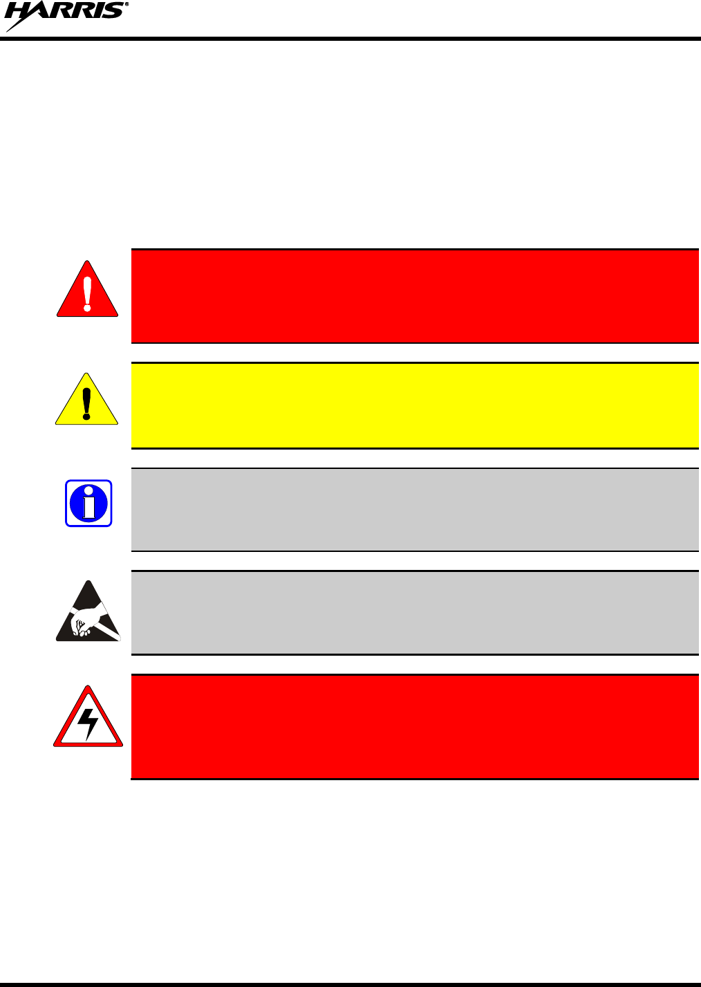
1.1 SAFETY CONVENTIONS
The following conventions are used throughout this manual to alert the user to general safety precautions
that must be observed during all phases of operation, service, and repair of this product. Failure to comply
with these precautions or with specific warning elsewhere in this manual violates safety standards of
design, manufacture, and intended use of the product. Harris assumes no liability for the customer’s
failure to comply with these standards.
The WARNING symbol calls attention to a procedure, practice, or the like, which, if
not correctly performed or adhered to, could result in personal injury. Do not
proceed beyond a WARNING symbol until the conditions identified are fully
understood or met.
The CAUTION symbol calls attention to an operating procedure, practice, or the like,
which, if not performed correctly or adhered to, could result in damage to the equipment
or severely degrade the equipment performance.
The NOTE symbol calls attention to supplemental information, which may improve
system performance or clarify a process or procedure.
The ESD symbol calls attention to procedures, practices, or the like, which could expose
equipment to the effects of Electro-Static Discharge. Proper precautions must be taken to
prevent ESD when handling circuit modules.
The electrical hazard symbol indicates there is an electrical hazard present.
WARNING
CAUTION
NOTE
14221-1100-2010, Rev. E
14
1.2 SAFETY TRAINING INFORMATION
The Harris XG-75P portable radio generates RF electromagnetic energy during
transmit mode. This radio is designed for and classified as “Occupational Use
Only,” meaning it must be used only during the course of employment by
individuals aware of the hazards and the ways to minimize such hazards. This
radio is NOT intended for use by the “General Population” in an uncontrolled
environment.
The XG-75P portable radio has been tested and complies with the FCC RF exposure limits for
“Occupational Use Only.” In addition, this Harris radio complies with the following Standards and
Guidelines with regard to RF energy and electromagnetic energy levels and evaluation of such levels for
exposure to humans:
FCC OET Bulletin 65 Edition 97-01 Supplement C, Evaluating Compliance with FCC Guidelines for
Human Exposure to Radio Frequency Electromagnetic Fields.
American National Standards Institute (C95.1 – 1992), IEEE Standard for Safety Levels with Respect
to Human Exposure to Radio Frequency Electromagnetic Fields, 3 kHz to 300 GHz.
American National Standards Institute (C95.3 – 1992), IEEE Recommended Practice for the
Measurement of Potentially Hazardous Electromagnetic Fields – RF and Microwave.
DIRECTIVE 2004/40/EC OF THE EUROPEAN PARLIAMENT AND OF THE COUNCIL of 29
April 2004 on the minimum health and safety requirements regarding the exposure of workers to the
risks arising from physical agents (electromagnetic fields) and amended by:
Directive 2007/30/EC of the European Parliament and of the Council of 20 June 2007
Directive 2008/46/EC of the European Parliament and of the Council of 23 April 2008
Regulation (EC) No 1137/2008 of the European Parliament and of the Council of 22 October 2008
Directive 2012/11/EU of the European Parliament and of the Council of 19 April 2012
1.2.1 RF Exposure Guidelines
To ensure that exposure to RF electromagnetic energy is within the FCC allowable
limits for occupational use and/or the exposure limit values in Annex A of EU Directive
2004/40/EC, always adhere to the following guidelines:
DO NOT operate the radio without a proper antenna attached, as this may damage the radio and may
also cause the FCC RF exposure limits and/or the exposure limit values in Annex A of EU Directive
2004/40/EC to be exceeded. A proper antenna is the antenna supplied with this radio by Harris or an
antenna specifically authorized by Harris for use with this radio. (Refer to Table 6-1.)
DO NOT transmit for more than 50% of total radio use time (“50% duty cycle”). Transmitting more
than 50% of the time can cause FCC RF exposure compliance requirements and/or the exposure limit
values in Annex A of EU Directive 2004/40/EC to be exceeded. The radio is transmitting when the
“TX” indicator appears in the display. The radio will transmit by pressing the “PTT” (Push-To-Talk)
button.
ALWAYS transmit using low power when possible. In addition to conserving battery charge, low
power can reduce RF exposure.
WARNING
CAUTION
14221-1100-2010, Rev. E
15
ALWAYS use Harris authorized accessories (antennas, batteries, belt clips, speaker/mics, etc). Use of
unauthorized accessories may cause the FCC Occupational/Controlled Exposure RF compliance
requirements and/or the exposure limit values in Annex A of EU Directive 2004/40/EC to be
exceeded. (Refer to Table 1-1.)
As noted in Table 1-1, ALWAYS keep the housing of the transmitter AT LEAST 1.6 cm (0.63
inches) from the body and at least 2.5 cm (1.0 inch) from the face when transmitting to ensure FCC
RF exposure compliance requirements and/or the exposure limit values in Annex A of EU Directive
2004/40/EC are not exceeded. However, to provide the best sound quality to the recipients of your
transmission, Harris recommends you hold the microphone at least 5 cm (2 inches) from mouth, and
slightly off to one side.
Table 1-1: RF Exposure Compliance Testing Distances
RADIO FREQUENCY
TESTED DISTANCES
(worst case scenario)
Body
Face
VHF (136 - 174 MHz)
1.6 cm
2.5 cm
UHF-L (378-470 MHz)
1.6 cm
2.5 cm
700-800 MHz
1.6 cm
2.5 cm
UHF-H (450-522 MHz)
1.6 cm
2.5 cm
Table 1-2: Distance from Body for Different Carrying Options
CARRYING CONFIGURATION
TESTED DISTANCES
(worst case from body)
Belt Clip
1.8 cm
Leather Case with Belt Loop
5.2 cm
Nylon Case with Belt Loop
4.5 cm
Shoulder Strap with D-clip
3.0 cm
Speaker-microphone with antenna
1.6 cm
The information in this section provides the information needed to make the user aware of RF exposure,
and what to do to assure that this radio operates within the FCC RF exposure and/or the exposure limit
values in Annex A of EU Directive 2004/40/EC limits.
1.2.2 Electromagnetic Interference/Compatibility
During transmissions, this Harris radio generates RF energy that can possibly cause interference with
other devices or systems. To avoid such interference, turn off the radio in areas where signs are posted to
do so. DO NOT operate the transmitter in areas that are sensitive to electromagnetic radiation such as
hospitals, aircraft, and blasting sites.
1.2.3 Radio Frequency Interference
1.2.3.1 Part 15
This device complies with Part 15 of the FCC Rules. Operation is subject to the following two conditions:
1. This device may not cause harmful interference, and
14221-1100-2010, Rev. E
16
2. This device must accept any interference received, including interference that may cause undesired
operation.
1.2.3.2 Industry Canada
This device complies with Industry Canada license-exempt RSS standard(s). Operation is subject to the
following two conditions: (1) this device may not cause interference, and (2) this device must accept any
interference, including interference that may cause undesired operation of the device.
1.3 OPERATING TIPS
Antenna location and condition are important when operating a portable radio. Operating the radio in low
lying areas or terrain, under power lines or bridges, inside of a vehicle or in a metal framed building can
severely reduce the range of the unit. Mountains can also reduce the range of the unit.
In areas where transmission or reception is poor, some improvement may be obtained by ensuring that the
antenna is vertical. Moving a few yards in another direction or moving to a higher elevation may also
improve communications. Vehicular operation can be aided with the use of an externally mounted
antenna.
Battery condition is another important factor in the trouble free operation of a portable radio. Always
properly charge the batteries.
1.3.1 Efficient Radio Operation
Keep the antenna in a vertical position when receiving or transmitting a message.
Do not hold the antenna when receiving a message and, especially, do not hold when transmitting a
message.
Do NOT hold onto the antenna when the radio is powered on!
1.3.2 Antenna Care and Replacement
Do NOT use the portable radio with a damaged or missing antenna. A minor burn
may result if a damaged antenna comes into contact with the skin. Replace a
damaged antenna immediately. Operating a portable radio with the antenna missing
could cause personal injury, damage the radio, and may violate FCC regulations.
Use only the supplied or approved antenna. Unauthorized antennas, modifications,
or attachments could cause damage to the radio unit and may violate FCC
regulations. (Refer to Table 6-1.)
WARNING
WARNING
WARNING
14221-1100-2010, Rev. E
17
1.3.3 Electronic Devices
RF energy from portable radios may affect some electronic equipment. Most modern
electronic equipment in cars, hospitals, homes, etc. is shielded from RF energy. However,
in areas in which you are instructed to turn off two-way radio equipment, always observe
the rules. If in doubt, turn it off!
1.3.4 Aircraft
Always turn off a portable radio before boarding any aircraft!
Use it on the ground only with crew permission.
DO NOT use while in-flight!!
1.3.5 Electric Blasting Caps
To prevent accidental detonation of electric blasting caps, DO NOT use two-way
radios within 1000 feet of blasting operations. Always obey the "Turn Off Two-Way
Radios" signs posted where electric blasting caps are being used. (OSHA Standard:
1926.900)
1.3.6 Potentially Explosive Atmospheres
Areas with potentially explosive atmospheres are often, but not always, clearly
marked. These may be fuelling areas, such as gas stations, fuel or chemical transfer
or storage facilities, and areas where the air contains chemicals or particles, such as
grain, dust, or metal powders.
Sparks in such areas could cause an explosion or fire resulting in bodily injury or
even death.
Turn off two-way radios when in any area with a potentially explosive atmosphere. It
is rare, but not impossible that a radio or its accessories could generate sparks.
CAUTION
WARNING
WARNING
WARNING
14221-1100-2010, Rev. E
18
2 RENSEIGNEMENTS SUR LA RÉGLEMENTATION ET
SÉCURITÉ
2.1 CONVENTIONS SUR LES SYMBOLES DE SÉCURITÉ
Les conventions suivantes sont utilisées dans le présent manuel pour avertir l’utilisateur des précautions
générales de sécurité qui doivent être observées pendant toutes les phases d’opération, d’entretien et de
réparation de ce produit. Le non-respect de ces précautions ou d’avertissements précisés ailleurs enfreint
les normes de sécurité de la conception, de la fabrication et de l’utilisation prévue du produit. Harris
n’assume aucune responsabilité pour le non-respect de ces normes par le client.
MISE EN GARDE
Le symbole MISE EN GARDE attire l’attention sur une procédure ou une
pratique qui, si elle n’est pas correctement effectuée ou observée, pourrait
entraîner une blessure personnelle. Ne pas poursuivre au-delà d’un symbole de
MISE EN GARDE avant que les conditions identifiées soient complètement
comprises ou satisfaites.
AVERTISSEMENT
Le symbole AVERTISSEMENT attire l’attention sur une procédure ou une pratique
opérationnelle qui, si elle n’est pas correctement effectuée ou observée, pourrait
entraîner un bris d’équipement ou une importante baisse de rendement de l’équipement.
REMARQUE
Le symbole REMARQUE attire l’attention sur des renseignements supplémentaires qui
peuvent améliorer le rendement du système ou clarifier un processus ou une procédure.
2.2 RENSEIGNEMENTS SUR LA FORMATION SUR LA SÉCURITÉ
MISE EN GARDE
La radio portative Harris XG-75P produit de l’énergie électromagnétique des RF
lorsqu’en mode de transmission. Cette radio est conçue et classée pour une
« Utilisation professionnelle seulement », ce qui signifie qu’elle ne doit être utilisée
que dans le cadre d’un emploi par des individus conscients des risques et des
moyens de limiter ceux-ci. Cette radio N’EST PAS conçue pour une utilisation par
la « Population générale » dans un environnement non contrôlé.
La radio portative XG-75P a été testée et est conforme aux limites d’exposition aux RF de la FCC pour
une « Utilisation professionnelle seulement ». De plus, cette radio Harris est conforme aux normes et
directives suivantes quant à l’énergie des RF et aux niveaux d’énergie électromagnétique, ainsi qu’à
l’évaluation de ces niveaux pour l’exposition aux humains :
Bulletin 65 du OET de la FCC, édition 97-01, supplément C, portant sur l’évaluation de la conformité
aux directives de la FCC quant à l’exposition humaine aux champs électromagnétiques des
radiofréquences.
American National Standards Institute (C95.1 – 1992), norme de l’IEEE sur les niveaux sécuritaires
d’exposition humaine aux champs électromagnétiques des radiofréquences, 3 kHz à 300 GHz.
American National Standards Institute (C95.3 – 1992), pratique recommandée par l’IEEE pour la
mesure des champs électromagnétiques potentiellement dangereux – RF et micro-ondes.
14221-1100-2010, Rev. E
19
2.2.1 Directives sur l’exposition aux RF
AVERTISSEMENT
Pour s’assurer que l’exposition à l’énergie électromagnétique des RF se situe dans les
limites acceptables de la FCC pour l’utilisation professionnelle, respectez toujours les
directives suivantes :
N’utilisez PAS la radio sans qu’une antenne appropriée y soit connectée, car ceci peut endommager la
radio et également causer un dépassement des limites d’exposition aux RF de la FCC. Une antenne
appropriée est celle fournie par Harris avec cette radio, ou une antenne spécifiquement autorisée par
Harris pour être utilisée avec cette radio. (Reportez-vous à Table 6-1.)
Ne transmettez PAS pendant plus de 50 % de la durée d’utilisation totale de la radio (« cycle de
service de 50 % »). La transmission pendant plus de 50 % du temps peut causer un dépassement des
exigences de conformité de la FCC en matière d’exposition aux RF. La radio transmet lorsque
l’indicateur « TX » apparaît sur l’affichage. La radio transmet lorsqu’on appuie sur le bouton « PTT »
(bouton de microphone).
Transmettez TOUJOURS en basse puissance lorsque possible. En plus de préserver la charge de la
pile, une faible puissance réduit l’exposition aux RF.
Utilisez TOUJOURS des accessoires autorisés Harris (antennes, piles, pinces de ceinture, haut-
parleurs/micros, etc.). L’utilisation d’accessoires non autorisés peut entraîner un dépassement des
exigences de conformité pour une exposition aux RF professionnelle ou contrôlée de la FCC.
(Reportez-vous à Table 1-1.)
Tel qu’indiqué dans Table 1-1, conservez TOUJOURS l’appareil et son antenne à AU MOINS 1,6 cm
(0,63 po) du corps, et à au moins 2,5 cm (1,0 po) du visage pendant la transmission, pour vous assurer
de ne pas dépasser les exigences de conformité de la FCC en matière d’exposition aux RF.
Cependant, pour offrir la meilleure qualité sonore aux auditeurs de votre transmission, Harris
recommande de tenir le microphone à au moins 5 cm (2 po) de votre bouche et légèrement déplacé
sur un côté.
Tableau 2-1: Distances de test de conformité des expositions aux RF
RADIOFRÉQUENCES
DISTANCES TESTÉES
(pire des scénarios)
Corps
Visage
VHF (136 - 174 MHz)
1,6 cm
2,5 cm
UHF-L (378-470 MHz)
1,6 cm
2,5 cm
700-800 MHz
1,6 cm
2,5 cm
UHF-H (450-522 MHz)
1,6 cm
2,5 cm
Tableau 2-2: Distance du corps pour différentes options de transport
CONFIGURATION DE TRANSPORT
DISTANCES TESTÉES
(DISTANCE MINIMALE AU CORPS)
Attache de ceinture
1,8 cm
Étui en cuir avec ganse de ceinture
5,2 cm
Étui en nylon avec ganse de ceinture
4,5 cm
Bandoulière avec attache en « D »
3,0 cm

14221-1100-2010, Rev. E
20
Microphone / Haut-parleur avec antenne
1,6 cm
Dans cette section figurent les renseignements nécessaires pour sensibiliser l’utilisateur à l’exposition aux
RF et sur ce qu’il faut faire pour s’assurer que cette radio fonctionne dans les limites d’exposition aux RF
de la FCC.
2.2.2 Interférence/Compatibilité Électromagnétique
Pendant les transmissions, cette radio Harris produit de l’énergie des RF qui peut causer de l’interférence
avec d’autres appareils ou systèmes. Pour éviter de telles interférences, fermez la radio dans les zones où
il est indiqué de le faire. N’utilisez PAS le transmetteur dans des zones sensibles aux radiations
électromagnétiques, comme les hôpitaux, les avions et les sites de détonation.
2.3 INTERFÉRENCE DES RADIOFRÉQUENCES
2.3.1 Partie 15 de la FCC
Cet appareil est conforme à la Partie 15 de la réglementation de la FCC. Le fonctionnement est soumis
aux deux conditions suivantes :
1. Cet appareil ne doit pas causer une interférence nuisible; et
2. Cet appareil doit accepter toute interférence reçue, y compris une interférence qui peut causer un
fonctionnement non souhaité.
2.3.2 Industrie Canada
Cet appareil est conforme aux normes RSS exemptées de licence d’Industrie Canada. Le fonctionnement
est soumis aux deux conditions suivantes : (1) cet appareil ne doit pas causer d’interférence et (2) cet
appareil doit accepter toute interférence, y compris une interférence qui peut causer un fonctionnement
non souhaité de l’appareil.
2.4 CONSEILS D’UTILISATION
L’emplacement et l’état de l’antenne sont importants pour l’utilisation d’une radio portative. L’utilisation
de la radio dans des zones de faible élévation, sous des lignes électriques ou des ponts, à l’intérieur d’un
véhicule ou dans un immeuble à ossature métallique, peut réduire la portée de l’appareil de manière
considérable. Les montagnes peuvent également réduire la portée de l’unité.
Dans les zones où la transmission ou la réception est insatisfaisante, certaines améliorations peuvent être
obtenues en s’assurant que l’antenne est verticale. Se déplacer de quelques mètres dans une autre
direction ou à un emplacement plus élevé peut également améliorer les communications. L’utilisation
d’une antenne fixée à l’extérieur peut faciliter le fonctionnement dans un véhicule.
L’état de la pile est un autre facteur important d’une utilisation sans tracas d’une radio portative. Chargez
toujours correctement la pile.
2.4.1 Utilisation Efficace de la Radio
Gardez l’antenne dans une position verticale pendant la réception ou la transmission d’un message.
14221-1100-2010, Rev. E
21
MISE EN GARDE
Ne tenez PAS l’antenne lorsque la radio est allumée!
2.4.1.1 Entretien Et Remplacement De L’antenne
MISE EN GARDE
N’utilisez pas la radio portative si son antenne est endommagée ou absente. Une
brûlure légère peut se produire au contact d’une antenne endommagée avec la peau.
Remplacez immédiatement une antenne endommagée. L’utilisation d’une radio
portative alors que l’antenne est absente peut causer des blessures, endommager la
radio et pourrait enfreindre la réglementation de la FCC.
AVERTISSEMENT
Utilisez seulement l’antenne fournie ou une antenne approuvée. Des antennes non
autorisées, des modifications ou des ajouts à une antenne peuvent endommager la radio et
enfreindre la réglementation de la FCC. (Reportez-vous à Table 6-1.)
2.4.1.2 Appareils Électroniques
AVERTISSEMENT
L’énergie des RF provenant de radios portatives peut affecter certains appareils
électroniques. La majorité de l’équipement électronique moderne dans les voitures, les
hôpitaux, les maisons, etc. est blindé contre l’énergie des RF. Cependant, dans les zones
où l’on vous demande de fermer l’équipement de radio bidirectionnelle, respectez toujours
les règles. En cas de doute, éteignez-le!
2.4.1.3 Avion
MISE EN GARDE
Éteignez toujours une radio portative avant d’embarquer à bord d’un avion!
Ne l’utilisez au sol qu’avec la permission de l’équipage.
NE l’utilisez PAS durant le vol!
2.4.1.4 Détonateurs Électriques
MISE EN GARDE
Pour prévenir la détonation accidentelle des détonateurs électriques, n’utilisez PAS
de radios bidirectionnelles à moins de 305 m (1 000 pi) des opérations de détonation.
Respectez toujours les indications « Éteindre les radios bidirectionnelles » situées là
où des détonateurs électriques sont utilisés. (Norme OSHA : 1926.900)

14221-1100-2010, Rev. E
22
2.4.1.5 Atmosphère Potentiellement Explosive
MISE EN GARDE
Les zones ayant une atmosphère potentiellement explosive sont souvent, mais pas
toujours, identifiées clairement comme telles. Il peut s’agir de zones d’alimentation
en carburant, comme les postes d’essence, les installations de stockage ou de
transfert de carburant ou de produits chimiques, ainsi que les zones dont l’air
contient des produits chimiques ou des particules, comme des grains, de la poussière
ou des poudres métalliques.
Des étincelles dans de telles zones peuvent provoquer une explosion ou un incendie,
causant ainsi des blessures ou même la mort.
Éteignez les radios bidirectionnelles dans toute zone ayant une atmosphère
potentiellement explosive. Il est rare, mais pas impossible qu’une radio ou ses
accessoires produisent des étincelles.
14221-1100-2010, Rev. E
23
3 CLEANING
Keep the exterior of the radio, battery, antenna, and radio accessories clean.
Periodically clean using the following procedures:
1. To remove dust and dirt, clean using damp clean cloth (warm water and mild detergent soap).
2. Follow by wiping with damp (warm water) clean cloth. Wipe dry with clean cloth
3. Remove the battery and wipe the battery and radio contacts using a soft dry cloth to remove dirt or
grease. This will ensure efficient power transfer from the battery to the radio.
4. Remove any accessories and clean the accessories Universal Device Connector (UDC) contacts using
a clean dry cloth. When the UDC is not in use, cover the connector with the protective dust cap to
prevent the build-up of dust or water particles.
5. If the radio is used in a harsh environment (such as driving rain, salt fog, etc.), it may be necessary to
periodically dry and clean the battery and radio contacts with a soft dry cloth or soft-bristle non-
metallic brush.
For more rigorous cleaning, use the following procedure:
CAUTION
Do not use chemical cleaners, spray, or petroleum-based products. They may damage
the radio housing. We recommend using Chemtronics® Electro-Wash® PR (ES-1603) or
equivalent.
1. Apply the cleaning solution to a clean damp cloth and clean the radio.
Do not spray cleaning solution directly on radio. To clean the radio in the speaker and
microphone areas, carefully wipe these areas but prevent the cleaning solution from
entering the speaker or microphone openings.
2. Wipe off the radio with clean damp cloth using mild warm soapy water.
3. Follow up by wiping off the radio with clean damp cloth using warm water only.
4. Wipe dry with clean cloth.
NOTE
14221-1100-2010, Rev. E
24
4 BATTERIES
The XG-75P series portable radios use rechargeable, recyclable Nickel Metal Hydride (NiMH), Lithium-
Ion (Li-Ion), or Lithium Polymer (Li-Poly) batteries. Please read the battery information provided
carefully to maximize the useful life of each type of battery.
WARNING
Do not disassemble or modify Lithium battery packs. Lithium battery packs are
equipped with built-in safety and protection features. Should these features be
disabled or tampered with in any way, the battery pack can leak electrolyte,
overheat, emit smoke, burst, and/or ignite.
If the battery is ruptured or is leaking electrolyte that results in skin or eye contact
with the electrolyte, immediately flush the affected area with water. If the battery
electrolyte gets in the eyes, flush with water for 15 minutes and consult a physician
immediately.
4.1 CONDITIONING BATTERY PACKS
4.1.1 Conditioning NiMH Battery Packs
Condition a new NiMH battery before putting into use. This also applies to rechargeable NiMH batteries
that have been stored for long periods (weeks, months, or longer). Conditioning requires fully charging
and fully discharging the battery three (3) times using the tri-chemistry charger. The first time the battery
is put into the charger, this unit will condition Nickel-based battery packs by automatically charging and
discharging (cycling) the battery. Refer to the appropriate charger manual for details.
Failure to properly condition NiMH battery packs before initial use will result in
shortened performance by the battery.
4.1.2 Conditioning Li-Ion or Li-Poly packs
Lithium battery packs do not suffer from memory effect and do not require conditioning.
4.2 STORING LI-ION BATTERY PACKS
If a battery pack is expected to be idle for a month or more, it should be properly prepared. Li-Ion battery
packs should not be stored fully charged. Before storing the battery pack, discharge it to 40% capacity. If
the battery is not discharged prior to storage, its overall capacity may be reduced. Although all battery
packs experience some capacity loss during storage, the shelf life for Li-Ion battery packs is about 3
months. However, note that any capacity drop which occurs during storage is permanent and cannot be
reversed. Li-Ion battery packs should be purchased and used immediately. They should not be stock-
piled without a rotating stock plan.
WARNING
CAUTION

14221-1100-2010, Rev. E
25
4.3 CHARGING BATTERY PACKS
Battery chargers are available from Harris with nominal charge times. Combinations include single and
multi-position charge units.
Harris chargers are specifically designed for charging nickel-based and lithium battery packs. The
chargers are chemistry-specific for the battery packs and automatically adjust the charging profiles
accordingly. Refer to the appropriate charger manual for specific operating instructions.
Observe the following guidelines when charging a battery pack:
Avoid high temperature during charging.
Discontinue use if the charger is overheating.
Only charge Harris battery packs using a charger approved for use by Harris.
Do not leave batteries in the charger indefinitely. For best results, leave the battery in the charger for
two to six hours after the Green Ready LED comes on. Then place the battery pack into service and
fully discharge (as indicated by the radio low battery warning) before re-charging.
If any faults are encountered while charging the battery pack, consult the charger’s manual to determine
the cause and possible corrective action.
4.4 BATTERY PACK USAGE
NiMH, Lithium-ion, and Lithium Polymer batteries vary in capacity and life cycle. NiMH, Lithium-Ion,
and Lithium Polymer batteries require that basic usage guidelines be followed in order to optimize the
battery runtime or shift life.
The following guidelines will help optimize the battery runtime or shift life:
Ensure Nickel-based battery packs are fully discharged (as indicated by the radio low battery
warning) before re-charging. Full discharge is not required for Lithium battery packs.
Periodically condition Nickel-based battery packs. The frequency should be determined based on
usage patterns (refer to ECR-7367). If the battery is fully discharged (to radio Low Battery warning)
during routine use, the frequency of conditioning may be reduced. Lithium-ion and Lithium Polymer
batteries do not suffer from memory-effect and therefore do not require conditioning.
Do not leave any Harris rechargeable batteries in a charger for more than a few days.
4.5 ADDITIONAL INFORMATION
For more information regarding the proper care of portable radio battery packs or establishing a battery
maintenance program, refer to ECR-7367 which may be ordered by calling toll free 1-800-368-3277
(international - 1-434-455-6403) or via https://premier.pspc.harris.com/infocenter/.
14221-1100-2010, Rev. E
26
4.6 CHANGING THE BATTERY PACK
4.6.1 Removing the Battery Pack
Make sure the power to the radio is turned off.
Although the XG-75P has been designed to tolerate changing the battery pack without
turning power off, Harris recommends turning the radio off before changing battery packs
to ensure safety and best operation.
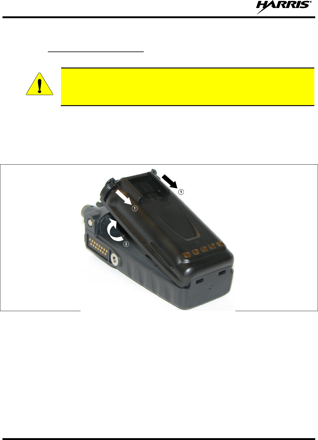
Refer to Figure 4-1 and perform the following to remove the battery pack.
1. Press or pull both latches on either side of the battery pack toward the bottom of the radio
simultaneously.
2. Pull the battery away from the radio.
3. Remove the battery pack from the radio.
Figure 4-1: Removing the Battery Pack
CAUTION
14221-1100-2010, Rev. E
27
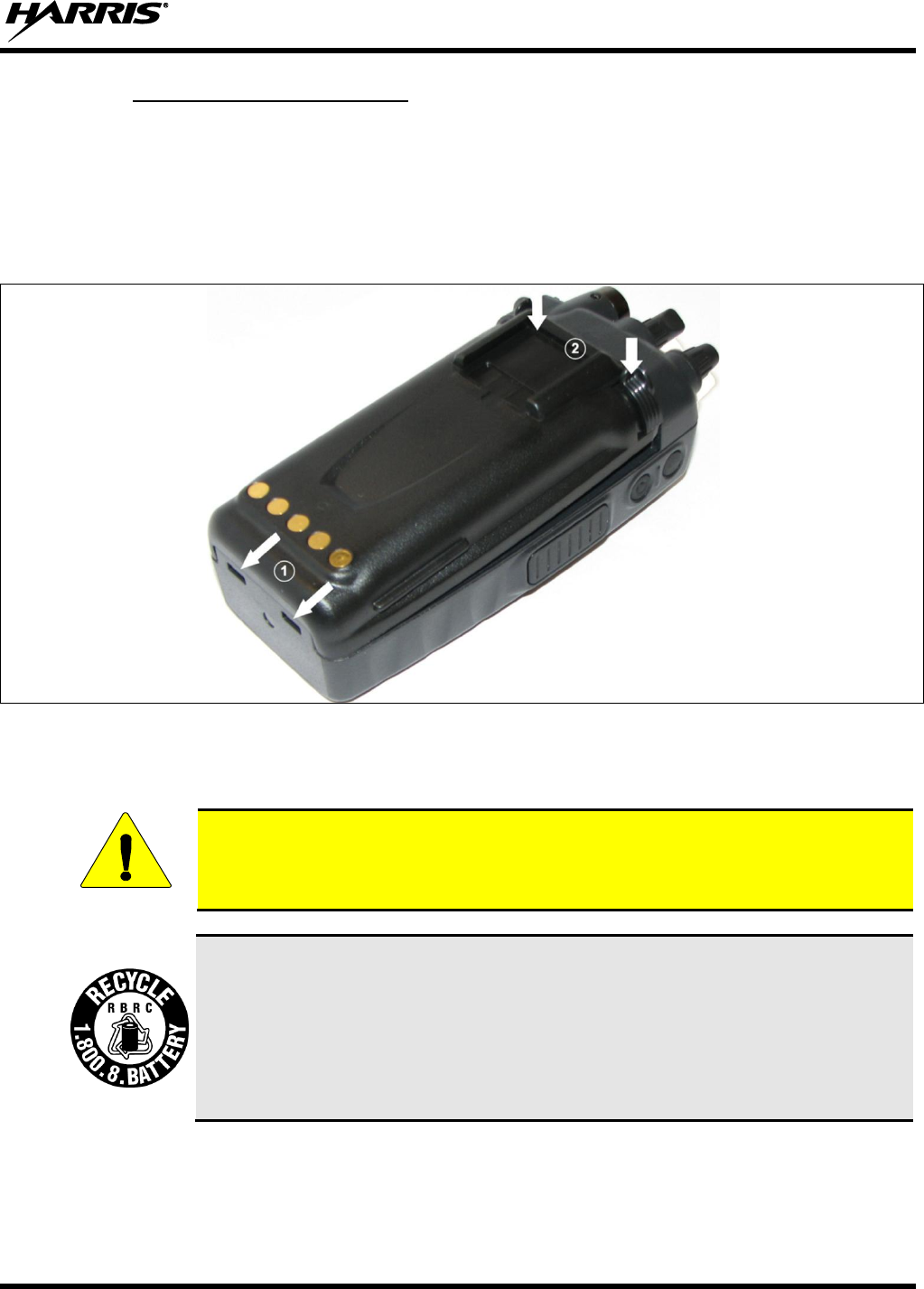
4.6.2 Attaching the Battery Pack
Make sure the power to the radio is turned off.
1. Align the tabs at each side on the bottom of the battery pack with the slots at the bottom of the battery
cavity .
2. Push the top of the battery pack down until the latches click to attach the battery to the radio.
3. Tug gently to verify that the latches are secure and the battery pack is properly attached to the radio.
Figure 4-2: Attaching the Battery Pack
4.7 BATTERY DISPOSAL
In no instance should a battery be incinerated. Disposing of a battery by burning will
cause an explosion.
RECHARGEABLE BATTERY PACK DISPOSAL – The product you have
purchased contains a rechargeable battery. The battery is recyclable. At the end of its
useful life, under various state and local laws, it may be illegal to dispose of this
battery into the municipal waste stream. Check with your local solid waste officials for
details in your area for recycling options or proper disposal. Canadian and U.S. users
may call Toll Free 1-800-8-BATTERY® for information and/or procedures for
returning rechargeable batteries in your locality.
CAUTION

14221-1100-2010, Rev. E
28
5 INTRODUCTION
The XG-75P is available in two models: the Scan model with a limited 6-button front-mounted keypad
and the System model with a 15-button DTMF front-mounted keypad. The Harris XG-75P portable radio
delivers end-to-end encrypted digital voice and IP data communications. It is designed to support
multiple operating modes including:
EDACS® (Enhanced Digital Access Communications System) or ProVoice™ Trunked Modes
P25 Trunked Mode
P25 Digital Conventional Mode
OpenSky® Trunked Protocol (700/800 MHz radio only)
Conventional Analog Mode
The XG-75P portables can include all of these modes or just one. Additional modes of operation can be
added with software updates.
The XG-75P supports a full range of advanced digital trunking features, including talk group calls,
priority scanning, emergency calls, late call entry, and dynamic reconfiguration. It performs autonomous
roaming for wide area applications. High quality voice coding and robust audio components assure
speech clarity.
In the trunked modes, the user selects a communications “operating” system (i.e., EDACS, ProVoice, or
P25) and group. While communicating in a trunked mode, channel selection is transparent to the user and
is controlled via digital communication with the system controller (e.g., a CSD in an EDACS system).
This provides advanced programmable features and fast access to communication channels.
In Conventional Analog mode, the user selects a channel and communicates directly on that channel. A
channel is a transmit/receive radio frequency pair.
The exact operation of the radio will depend on the operating mode, the radio’s programming, and the
particular radio system. Most features described in this manual can be enabled through programming.
Consult your System Administrator for the particular features programmed into your XG-75P. Then refer
to the corresponding section(s) within this manual for feature and operation information.
The XG-75P series portable radios operate reliably even under adverse conditions. These radios meet
MIL-STD-810G specifications for wind driven rain, humidity, and salt fog.
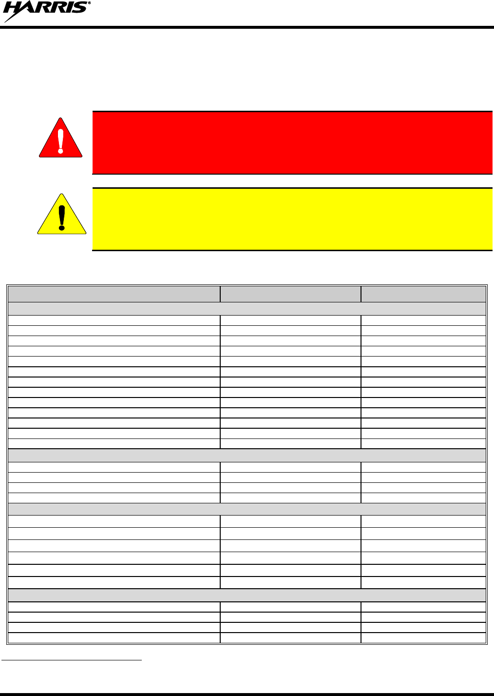
14221-1100-2010, Rev. E
29
6 OPTIONS AND ACCESSORIES
Table 6-1 lists the Options and Accessories tested for use with the XG-75P series portable radios. Refer to
the Harris Products and Services Catalog for a complete list of options and accessories, including those
items that do not adversely affect the RF energy exposure.
Always use Harris authorized accessories (antennas, batteries, belt clips,
speaker/mics, etc). Use of unauthorized accessories may cause the FCC
Occupational/Controlled Exposure RF compliance requirements to be exceeded.
(Refer to Table 1-1.)
Always use the correct options and accessories (battery, antenna, speaker/mic, etc.) for the
radio. Immersion rated options must be used with an immersion rated radio. Intrinsically
safe options (identified by [FM]) are certified by Factory Mutual (FM) and must only be
used with FM certified radios. (Refer to Table 6-1.)
Table 6-1: Options and Accessories1
DESCRIPTION
PART NUMBER
OPTION NUMBER
ANTENNAS
Helical coil (136-151 MHz) [FM]
KRE 101 1219/1
EVXG-NC1B
Helical coil (150-162 MHz) [FM]
KRE 101 1219/2
EVXG-NC1C
Helical coil (162-174 MHz) [FM]
KRE 101 1219/3
EVXG-NC1D
Helical coil (150-174 MHz) [FM]
KRE 101 1219/21
EVXG-NC5W
Helical stub (378-403 MHz) [FM]
KRE 101 1219/9
EVXG-NC5B
Helical stub (403-430 MHz) [FM]
KRE 101 1219/10
EVXG-NC1U
1/4 - wave whip (378-430 MHz) [FM]
KRE 101 1223/10
EVXG-NC1L
Helical stub (430-470 MHz) [FM]
KRE 101 1219/12
EVXG-NC1F
Wideband whip (764-870 MHz) [FM]
KRE 101 1506/2
MAEV-NNC5X
1/2 - wave (764-870 MHz) [FM]
KRE 101 1506/1
MAEV-NNC5K
Helical Stub (470-512 MHz)
KRE 101 1219/14
MAEV-NNC5Y
¼ Wave Whip (440-512 MHz)
KRE 101 1223/12
MAEV-NNC1N
Helical Stub (470-512 MHz)
KRE 101 1219/13
XXNC1G
BATTERIES
Nickel Metal Hydride (NiMH) Battery, Immersible
BT-023406-003
MAEV-NPA9X
NiMh Battery, [FM]
BT-023406-004
MAEV-NPA2A
Lithium-Ion (Li-Ion) Battery, Immersible
BT-023406-005
MAEV-NPA9Y
Lithium Polymer, Immersible
BT-023436-001
MAEV-PA2U
CHARGERS
Power Adapter Kit, VC4000 Charger
PS-007810-001
MAH2-NPS9X
VC4000 Tri-Chemistry Charger
CH-017231-001
MAH2-VC4PB
Single Charger, Tri-Chemistry
CH-104560-007
MAEV-NCH9T
6-bay Charger, Li-Ion/Polymer
12082-0314-01
MAEV-CH4B
Wall Mount Kit, 6-Bay Li-Ion/Poly Charger
12082-0315-01
MAEV-AE4A
Charger, 6-Bay, Tri-Chemistry
CH-104570-007
MAEV-NCH9U
AUDIO ACCESSORIES
Speaker Mic without Antenna (cc) provision, [FM]
MC-023933-001
MAEV-NAE9D
Rugged Speaker Mic, Antenna, Straight, SBR [FM]
MC-011617-602
MAEV-NAE6D
Earphone for Speaker Mic, [FM]
LS103239V1
MAEV-NAE3Z
Earphone for Speaker Mic, right angle jack
LS103239V2
EV-AE1K
1 Options and Accessories table updated in 14221-1100-2010, Rev. E.
WARNING
CAUTION

14221-1100-2010, Rev. E
30
DESCRIPTION
PART NUMBER
OPTION NUMBER
GPS
MC-009104-002
MAEV-NAE9R
Ruggedized Speaker Mic-Coil Cord [FM]
MC-011617-601
MAEV-NAE6C
Standard Speaker Mic - Non Ant [FM]
MC-011617-701
MAEV-NAE6A
Rugged Speaker Mic, Coiled Cord, Hi-Visibility
MC-011617-606
EV-AE4C
Speaker Mic, Straight Cord, 25.6in, Antenna
MC-011617-703
MAEV-AE6L
Speaker Mic, Antenna, Straight, 18in
MC-011617-718
MAEV-AE6M
Speaker Mic, Antenna, Straight, 30in
MC-011617-730
MAEV-AE6N
Speaker Mic, Rugged, Coiled, Hirose Port
MC-011617-611
EV-AE4K
DROP SHIP AUDIO ACCESSORIES
Earphone Kit, Black
EA-009580-001
Earphone Kit, Beige
EA-009580-002
2-Wire Kit, Palm Mic, Black
EA-009580-003
2-Wire Kit, Palm Mic, Beige
EA-009580-004
3-Wire Kit, Mini-Lapel Mic, Black
EA-009580-005
3-Wire Kit, Mini-Lapel Mic, Beige
EA-009580-006
Explorer Headset with PTT
EA-009580-007
Lightweight Headset Single Speaker with PTT
EA-009580-008
Breeze Headset with PTT
EA-009580-009
Headset, Heavy Duty, N/C Behind-the-Head, with PTT
EA-009580-010
Ranger Headset with PTT
EA-009580-011
Skull Mic with Body PTT and Earcup
EA-009580-012
Headset, Heavy Duty, N/C Over-the-Head, with PTT
EA-009580-013
Throat Mic with Acoustic Tube and Body PTT
EA-009580-014
Throat Mic with Acoustic Tube, Body PTT, and Ring
PTT
EA-009580-015
Breeze Headset with PTT and Pigtail Jack
EA-009580-016
Hurricane Headset with PTT
EA-009580-017
Hurricane Headset with PTT and Pigtail Jack
EA-009580-018
CARRYING CASE ACCESSORIES
Black Nylon Case with Belt Loop Kit
14011-0012-01 contains:
14011-0011-01
CC-014527
MAEV-NHC2A
Orange Nylon Case with Belt Loop Kit
14011-0012-02 contains:
14011-0011-02
CC-014527
MAEV-NHC2B
Leather Case with Belt Loop Kit
14011-0012-03 contains:
14011-0011-03
KRY1011608/2
CC-014527
MAEV-NHC2C
Leather Case with Shoulder Strap Kit
14011-0012-04 contains:
14011-0011-04
KRY1011608/2
CC-014524-001
MAEV-NHC2D
Short Leather Retaining Strap (use with Shoulder
Strap application)
CC-014524-002
MAEV-NHC2E
Metal Belt Clip
CC23894
MAEV-NHC2G
Strap Holder, “T”
KRY 101 1656/1
MAEV-NHC2J
Belt Loop, Leather with Swivel
KRY1011609/1
FM-017262-001
MAEV-NHC7T

14221-1100-2010, Rev. E
31
7 CHANGE OPERATING MODE
7.1 CHANGE FROM OTP MODE
To change from OTP operating mode to EDACS/P25/Conventional (ECP):
1. Use or to cycle through the menu until “App Mode” is displayed.
2. Use or to choose an available mode. Press and or to confirm (Y/N).
3. Press the button to confirm.
Or
With a system model radio, press 1# to transition to ECP.
Or
If configured turn the A/B Switch to the A or B position.
7.2 CHANGE TO OTP MODE
1. Use or to scroll through available systems until OpenSky is displayed and wait.
2. The radio transitions to OTP mode.
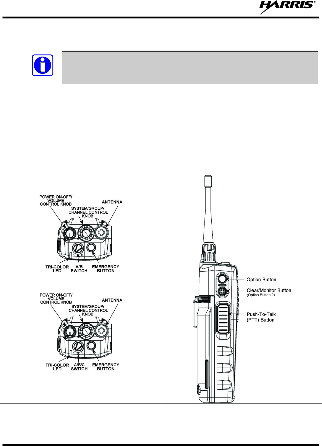
14221-1100-2010, Rev. E
32
8 OPENSKY OPERATION
OpenSky is only available in the 700/800 MHz model of the XG-75P series portable
radios.
Once an OpenSky system has been selected from the available systems on the XG-75P series portable
radio, the characteristics described in the following sections will govern operation.
8.1 CONTROLS
The XG-75P portable radio features two rotary control knobs, an emergency button, and a dual-position
A/B switch, all located on the top of the radio. Refer to Figure 9-1. The Push-To-Talk (PTT) button and
two option buttons are located to the left side of the radio keypad (see Figure 9-2). The front mounted
keypad of the System model has 15 buttons and the Scan model has six buttons (refer to Figure 8-3 and
Figure 8-4).
With A/B Switch
With A/B/C Switch
Figure 8-1: Top View
Figure 8-2: Side View
NOTE
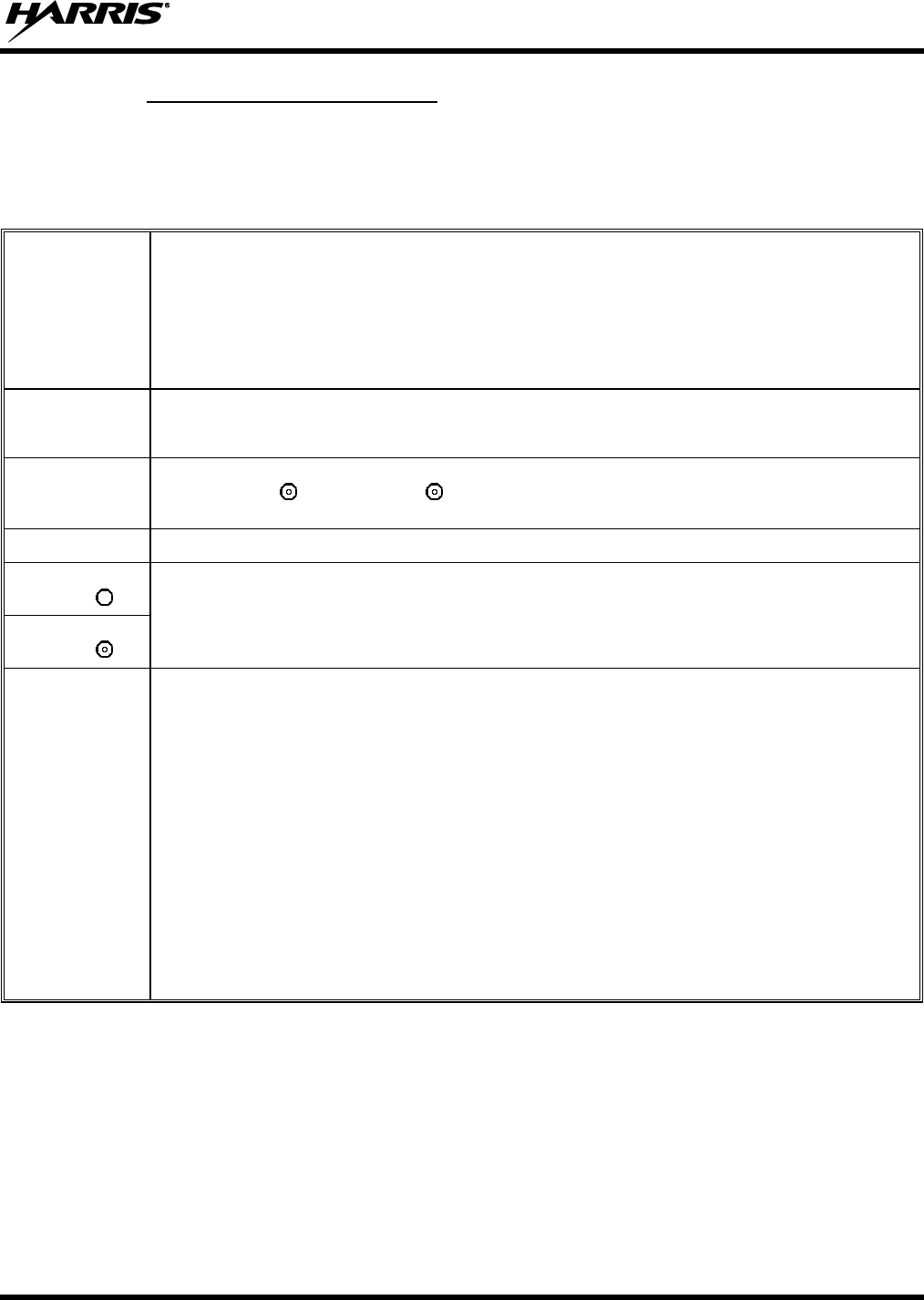
14221-1100-2010, Rev. E
33
8.1.1 Buttons, Knobs, and Switch
The functions of the buttons, knob controls, and dual position A/B Switch vary depending on the mode of
operation. Their functions while in the OpenSky mode of operation are discussed in the following
paragraphs.
Table 8-1: Buttons, Knobs, and Switch Functions
POWER
ON-OFF
VOLUME KNOB
The Power On-Off/Volume Knob is rotated to apply power to the radio and adjust audio volume up and
down.
Rotating the control clockwise applies power to the radio. Rotating the control clockwise increases the
volume level. Minimum volume levels may be programmed into the radio to prevent missed calls due to
a low volume setting. While adjusting the volume, the display will momentarily indicate the volume level
(e.g., VOL=39). The volume range is from a minimum programmed level of 1 (displayed as OFF in the
display) up to 39, which is the maximum level.
VOICE GROUP
SELECTION
KNOB
Used to select voice groups when operating within an OpenSky system. This is a 16-position rotary
knob. A channel stopper ring (14002-0169-02) is available from Harris’ Customer Care center. Refer to
Installation Guide 14221-110-4040 for installation instructions.
EMERGENCY
BUTTON
Press the emergency button to declare an emergency. To clear an emergency, press and hold the
Option 2 button . While holding , press the emergency button. Release both buttons when the
“emergency cleared” tone sounds.
PTT BUTTON
The Push-To-Talk button must be pressed before voice transmission begins.
SIDE OPTION
BUTTON 1
Scrolls UP or DOWN through available items within a sub-menu, such as available talk groups, pre-
programmed speed dial numbers, canned alert messages, etc.
SIDE OPTION
BUTTON 2
A/B SWITCH
OR
A/B/C SWITCH
The following settings are configurable via the at@abcswitch command:
No Action.
V-TAC Detach (same as *60).
V-TAC Attach (same as *61, *62, or *62 depending on at@cmode setting).
Change to ECP mode.
Scan Mode - No Scan (See Section 8.24.1).
Scan Mode - Normal (See Section 8.24.1).
Scan Mode - Fixed (See Section 8.24.1).
Voice Encryption OFF - If the Selected Talk Group is voice encrypted disable voice encryption on
transmit.
Voice Encryption ON - If the Selected Talk Group is voice encrypted enable voice encryption on
transmit.
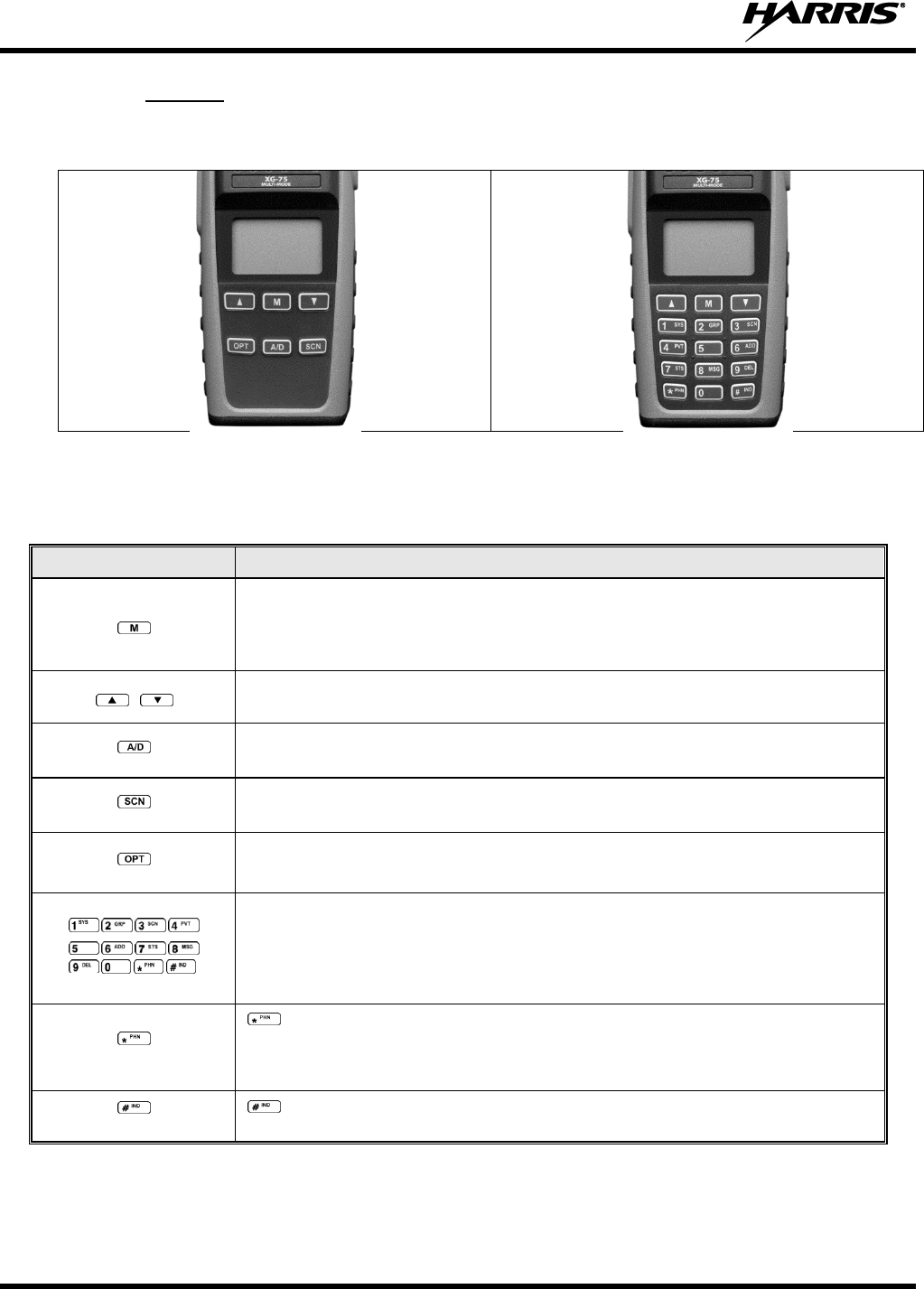
14221-1100-2010, Rev. E
34
8.1.2 Keypad
The front mounted keypad of the Scan model has six buttons and System model has 15 buttons. Refer to
Figure 8-3 and Figure 8-4, respectively.
Figure 8-3: Scan Model Front Panel
Figure 8-4: System Model Front Panel
In OTP mode, numeric entry is the primary function of the keys. Each key is described in Table 8-2.
Table 8-2: Keypad Functions
KEY
FUNCTION
Primary function: Acts much as an “enter” button to activate a selection.
Secondary function: While in the “dwell display,” press repeatedly to scroll through and
view status display (on 2nd line) for current profile, caller, received talk group, and
channel.
Scrolls through available menu items (see Table 8-5).
(Scan Model only)
Currently undefined in OpenSky mode.
(Scan Model only)
Toggles scan mode On/Off.
(Scan Model only)
Currently undefined in OpenSky mode.
(System Model Only)
The numeric keys are used to enter passwords for logging into the OpenSky network, if
not pre-configured for automatic registration at power-up.
Also used to place telephone interconnect and individual (unit-to-unit) calls, operating
like a normal telephone keypad. Additional functions are also available, such as speed
dial, quick access to V-TAC, voice scanning, and Stealth mode operation.
(System Model Only)
Initiates OpenSky functions (log in, log out, selective call, telephone interconnect
call, etc.). See page 42 for additional information. It is also used as an escape or to
clear an entry (something like backspace, but it clears everything, not only the last
digit/character).
(System Model Only)
Used in conjunction with alpha-numeric keys for passwords and OpenSky
functions. See page 42 for additional information.
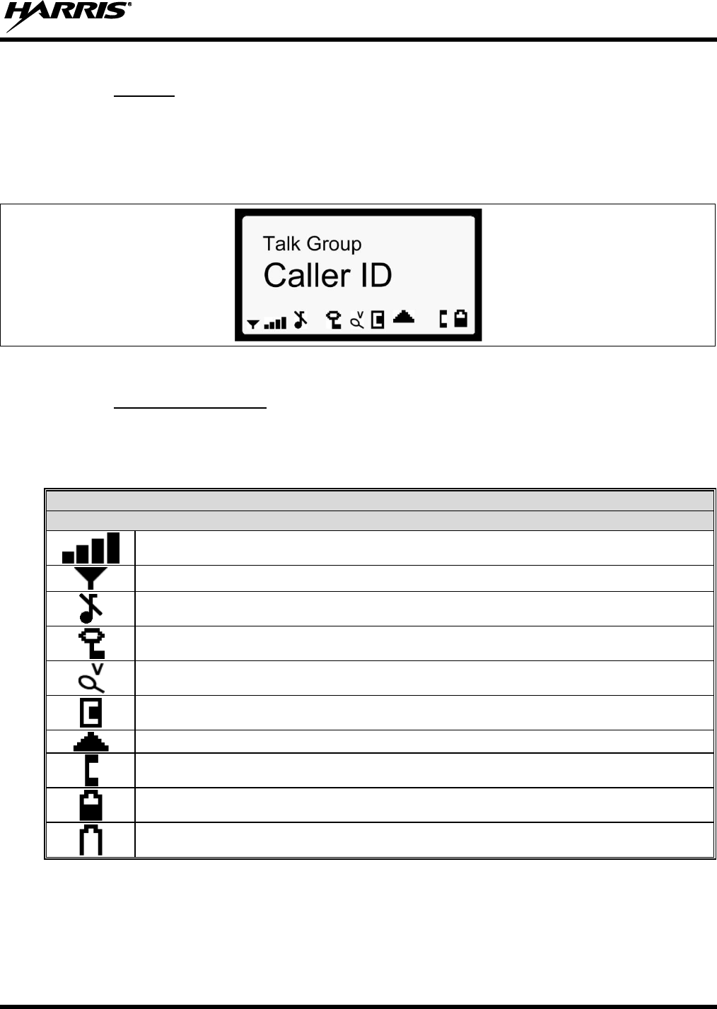
14221-1100-2010, Rev. E
35
8.1.3 Display
The XG-75P display is made up of four lines containing twelve alpha-numeric character blocks each.
The 3rd line also contains twelve blocks, each used to display radio status icons. If programmed, the
display backlighting will illuminate upon power up or when radio controls are operated. Specific display
characteristics will be discussed in following sub-sections.
Figure 8-5: Radio Display OpenSky Mode
8.1.4 Radio Status Icons
Status Icons indicate the various operating characteristics of the radio. The icons show operating modes
and conditions and appear on the third line of the display (see Table 8-3).
Table 8-3: Status Icons Descriptions
STATUS ICON DESCRIPTIONS
OPENSKY ICONS
Steady – Received Signal Strength Indicator (RSSI).
Steady – Radio is data registered.
Steady – Stealth mode is enabled, all tones and the display backlight are disabled, voice is still heard.
Steady - Radio is transmitting or receiving an encrypted voice call.
Animated – The radio is scanning for a V-TAC. Once the radio has attached to a V-TAC, the icon will turn off.
V-TAC Connection Indicator – Indicates the client is connected to a V-TAC.
Steady – Indicates Voice Scan mode is Normal or Fixed. Is not displayed when Voice Scan mode is No Scan.
Steady – Indicates Selective Call mode.
Steady – Battery charge indicator.
Flashing – Low battery indicator.
The battery charge indicator illustrates approximate charge only, based on battery voltage.
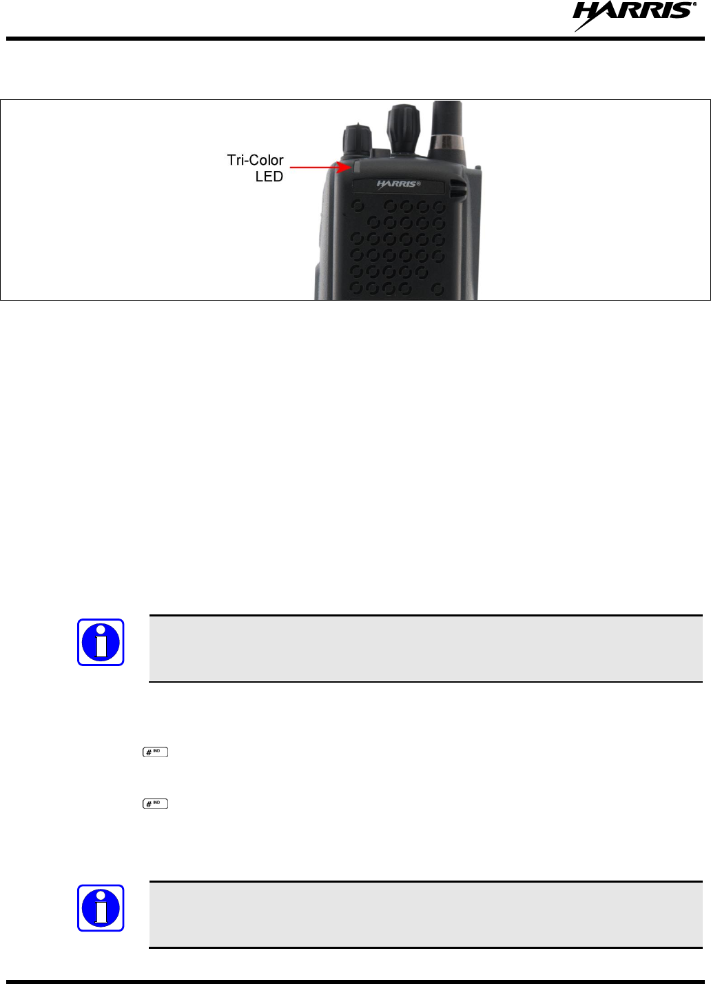
14221-1100-2010, Rev. E
36
8.2 TRI-COLOR LED
Figure 8-6: Tri-Color LED
The Tri-Color LED changes color to indicate radio status and is visible from both the front and top of the
radio (see Figure 8-6).
In OpenSky mode the following radio states are reflected by the LED and the status they represent are:
Green: Receiving
Red: Transmitting
Orange: If the LED is flashing rapidly, the radio is receiving an emergency call. If the
LED is flashing every ½ second, the selected talk group is in the emergency state
(although not transmitting). If the selected talk group is in the emergency state,
an asterisk will be displayed next to the talk group name.
8.3 LOG IN TO THE NETWORK
Login occurs either automatically (auto registration) if the radio has a valid registration or, if enabled,
requires the user to enter a User ID and password.
The user will be prompted with “Pls Login” if one talk group in the selected profile can
be encrypted. The user has to login to use that talk group in encrypted mode.
1. Press *1 keys (Login command).
2. Enter the full 10-digit User ID.
3. Press the key.
4. Enter the password.
5. Press the key.
The User ID may be remembered from the previous log-in. (Refer to Section 8.4 for further details
regarding log-off commands.) The password will be established before the radio is put into operation.
Contact the local OpenSky network administrator for more information.
If necessary, contact radio system administration personnel for log-in assistance and/or
radio-specific log-in instructions.
NOTE
NOTE
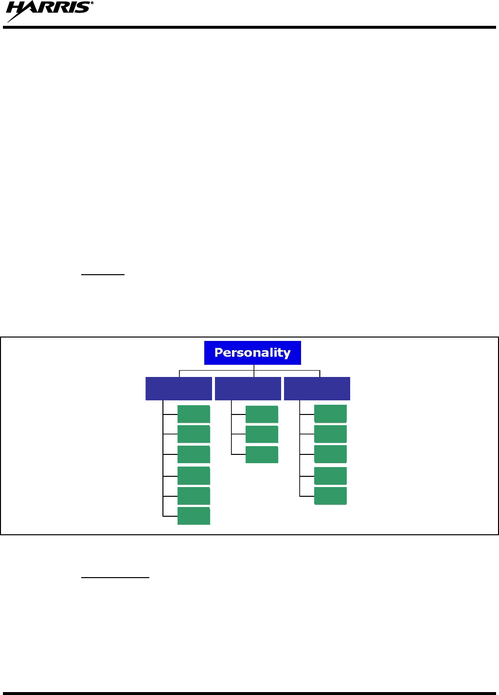
14221-1100-2010, Rev. E
37
8.4 LOG OFF THE NETWORK
The *0## command de-registers the radio. Typically, this is automatically performed when powering
down the radio. Using this method, the User ID is remembered by the radio, so only the password is
needed at next log-in. If a user is logged in, it is necessary to log-off.
8.5 PERSONALITY
As illustrated in Figure 8-7, a personality defines the profiles and talk groups available to the user. It is
the structuring of a collection of profiles and privileges established by the OpenSky network administrator
to provide the user with a comprehensive set of profiles to communicate effectively with the necessary
talk groups or individuals.
Personalities are stored on the network and downloaded over-the-air to the radio. This process is called
“provisioning.” Provisioning occurs at radio power-up (if the personality is not already stored in the
radio’s memory) and at user log-in (if the radio has been deregistered). When changes are made to the
personality, the radio is automatically re-provisioned. Each personality can contain up to 16 profiles and
each profile can contain up to sixteen talk groups.
8.5.1 Profiles
As stated above, each profile can contain up to 16 talk groups. A profile also defines the radio’s
emergency behavior. All transmissions are made on the selected talk group (displayed on the top line of
the dwell display). The user can change the selected talk group to any of the other talk groups within the
profile.
Figure 8-7: Personality Structure Example
8.5.2 Talk Groups
A talk group represents a set of users that regularly need to communicate with one another. There can be
any number of authorized users assigned to a talk group. Talk groups are established and organized by the
OpenSky network administrator. An OpenSky talk group is similar to a channel within a conventional
FM radio system.
TG a
TG b
TG c
TG x
TG y
TG z
TG d
TG e
TG f
TG a
TG d
TG g
TG h
TG i
TG = Talk Group
Profile 1
Profile 2
Profile 3

14221-1100-2010, Rev. E
38
8.6 OPENSKY DISPLAY OVERVIEW
The 12-character x 3-line display shows the radio status. The first two lines of the display are text lines
that change in response to user interaction with the menu buttons. Status icons appear in the bottom line
(line 3) of the display (see Table 8-3).
8.6.1 Display’s Top Line
The display’s top line of text changes as the and buttons are pressed to scroll through the
available menu options (see Table 8-5). When the dwell display is present, the selected talk group will be
displayed. Other information, such as alert messages will scroll across the top line of the display.
8.6.2 Display’s Second Line
The second line will display information such as active menu, login prompt, emergency status, and dwell
display messages as described in the following section.
8.6.3 Dwell Display
When not engaged in menu selection, the first two lines of the display default to the user-defined display,
known as the “dwell display.” The top line indicates the currently selected talk group. The second line
will display the currently selected profile, caller ID/alias2, received talk group, and current channel name
if the channel menu is enabled. Press the button repeatedly to scroll through and view one of these
second line options.
8.7 ALERT TONES
The XG-75P radio also provides audible Alert Tones or “beeps” to indicate the various operating
conditions (see Table 8-4).
Table 8-4: Alert Tones
NAME
TONE
DESCRIPTION
Call Queued
One low tone/two high tones
Call is queued for processing.
Call Denied
Three short beeps
Radio is out of coverage area or requested talk group is active.
Grant (or Go-Ahead)
Single short beep
Sounded when resources become available for a call request
placed in the queue (if enabled) upon channel access.
If the radio roams to another site while transmitting, then it will
auto rekey and begin transmitting on that tower. It gives a
second grant tone to let the user know they have roamed.
Call Removed
Single long low-pitched tone
Notifies the user access to the channel has been lost (out of
coverage area or pre-empted by higher-priority call).
Low Battery
One low-pitched/one short mid-
pitched
Low battery.
Selective Alert Received
Four short tones
Only played once to indicate a selective alert has been
received.
Emergency Alert Tone
Three long beeps
Sounds when an emergency alert is declared.
Emergency Cleared Tone
Single long low-pitched tone
Sounds when an emergency is cleared.
2 Alias is a logical ID name such as “J_Smith.” The name corresponds to a user ID such as 003-542-0001.

14221-1100-2010, Rev. E
39
NAME
TONE
DESCRIPTION
Selective Call Ring Tone
A ringing tone similar to a
telephone
Ringing is repeated every four (4) seconds until the call is
accepted or rejected by the radio being called or until the
network drops the call if unanswered after one (1) minute.
Roam Tone
Two short tones, one high-
pitched and one low-pitched
Sounds when the radio transitions from one radio base station
site to another. While transmitting voice.
Out of Range Tone
Three brief tones
If enabled via programming, sounds at a programmable interval
while the radio is in a state of persistent deactivation.
Priority Bump
Single medium mid-pitched
tone.
Sounds when the current received call is preempted by a
higher priority call.
XCOV Connect Tone
or
Site Found Tone
Three short high-pitched tones.
Sounds when a radio connects to a V-TAC in XCOV, XCOV-
TG, or XCOV-Prof mode.
Sounds when the selected site is found using the Site Lock
Menu.
XCOV Disconnect Tone
or
Site Not Found Tone
Three short high-pitched tones.
Sounds when a radio connects to a V-TAC in XCOV, XCOV-
TG, or XCOV-Prof mode.
Sounds when the selected site is not found using the Site Lock
Menu.
Man Down Tone
Single long low-pitch tone
followed by a single short high-
pitched tone.
Sounds when the man down accessory is connect to the radio’s
UDC port and the radio is a horizontal.l
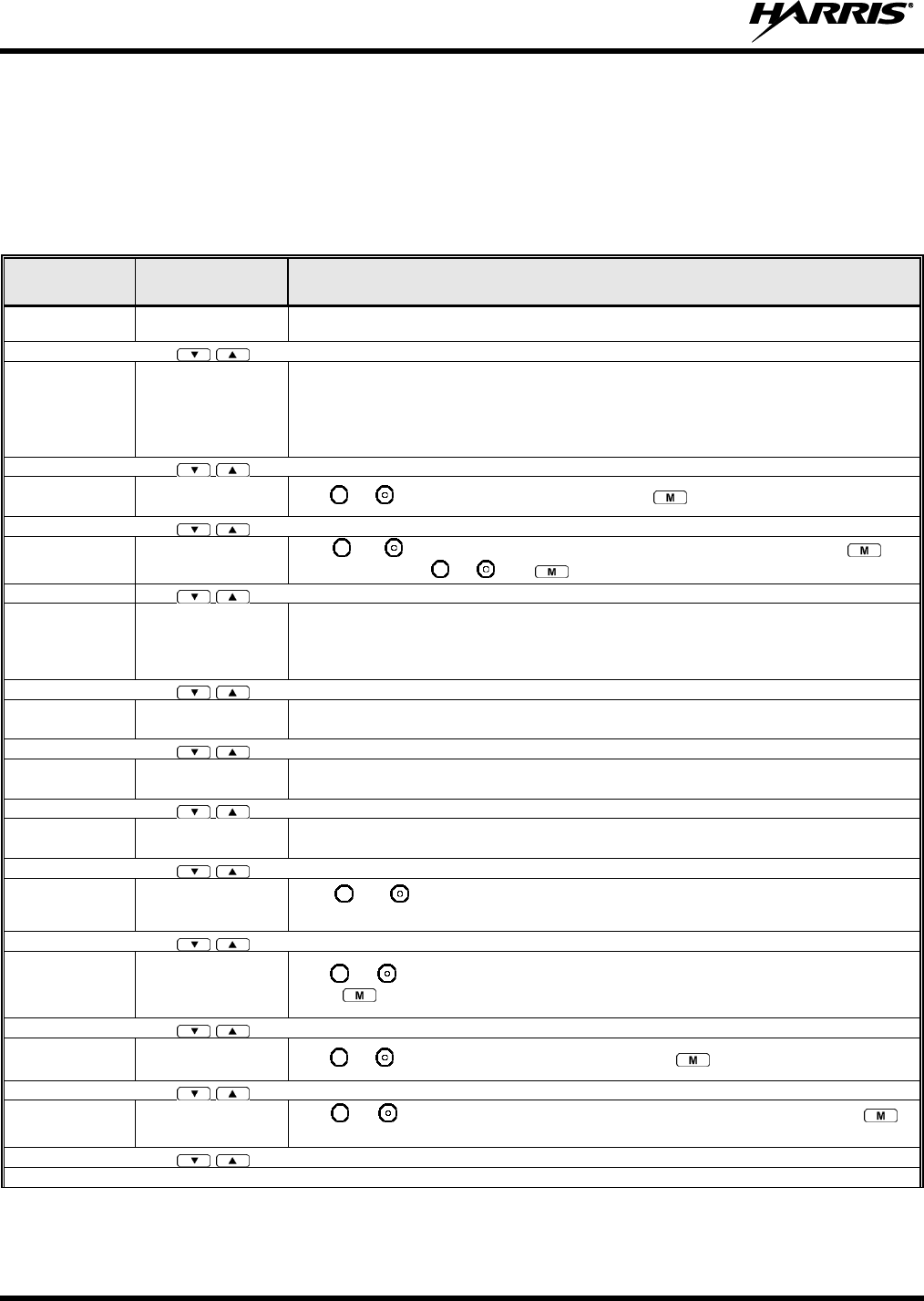
14221-1100-2010, Rev. E
40
8.8 BASIC MENU STRUCTURE
Table 8-5 illustrates the basic XG-75P OpenSky menu structure. Menu items will vary depending upon
system programming, radio hardware, and optional configurations. All menus except the dwell display
menu can be turned off by network administration personnel.
Table 8-5: Basic OpenSky Menu Structure
MENU
NAME
RADIO
DISPLAYS
USAGE NOTES
To/From Dwell
Display
Engineering
Display
bit-error rates,
RSSI data, sync
status, current
channel and
registration status
Displays radio system connection data. For engineering use.
Silent
Emergency
“SilentEmerg”
Use or to toggle between OFF/ON. Press to enable.
Operating Mode
“App Mode”
Use or to choose an available mode (OTP, OCF, or ECP). Press and
confirm (Y/N) with or and again.
GPS Fix
“GPS”
GPS latitude and longitude position of currently tuned-to base station [“GPS (Site)”] or
V-TAC (“GPS”) scrolls across top line of the display. “GPS (Aged)” indicates V-TAC
coordinates haven’t been updated for more that 2 minutes.
User ID
“User ID”
User’s identification/name scrolls across top line of the display (if programmed).
IP Address
“IP Address”
Radio’s Internet Protocol (IP) address scrolls across top line of the display.
Station
Identification
“Station ID”
Station’s identification/name scrolls across top line of the display (if programmed).
Stealth Mode
(display backlight
is disabled)
“StealthMenu”
Use or to turn Stealth Mode “On” or “Off.” See Section 8.17 for more
information about Stealth Mode.
Treble Level
“Treble Menu”
Use or to choose speaker treble level (LOW, MEDIUM, MEDHIGH, or HIGH).
Press to return to dwell display.
Display
Brightness
“Bright Menu”
Use or to brighten or dim backlighting. Press to return to dwell display.
Side Tone Level
“Side Menu”
Use or to choose side tone level (OFF, LOW, MED, or HIGH). Press to
return to dwell display.
See Next Page
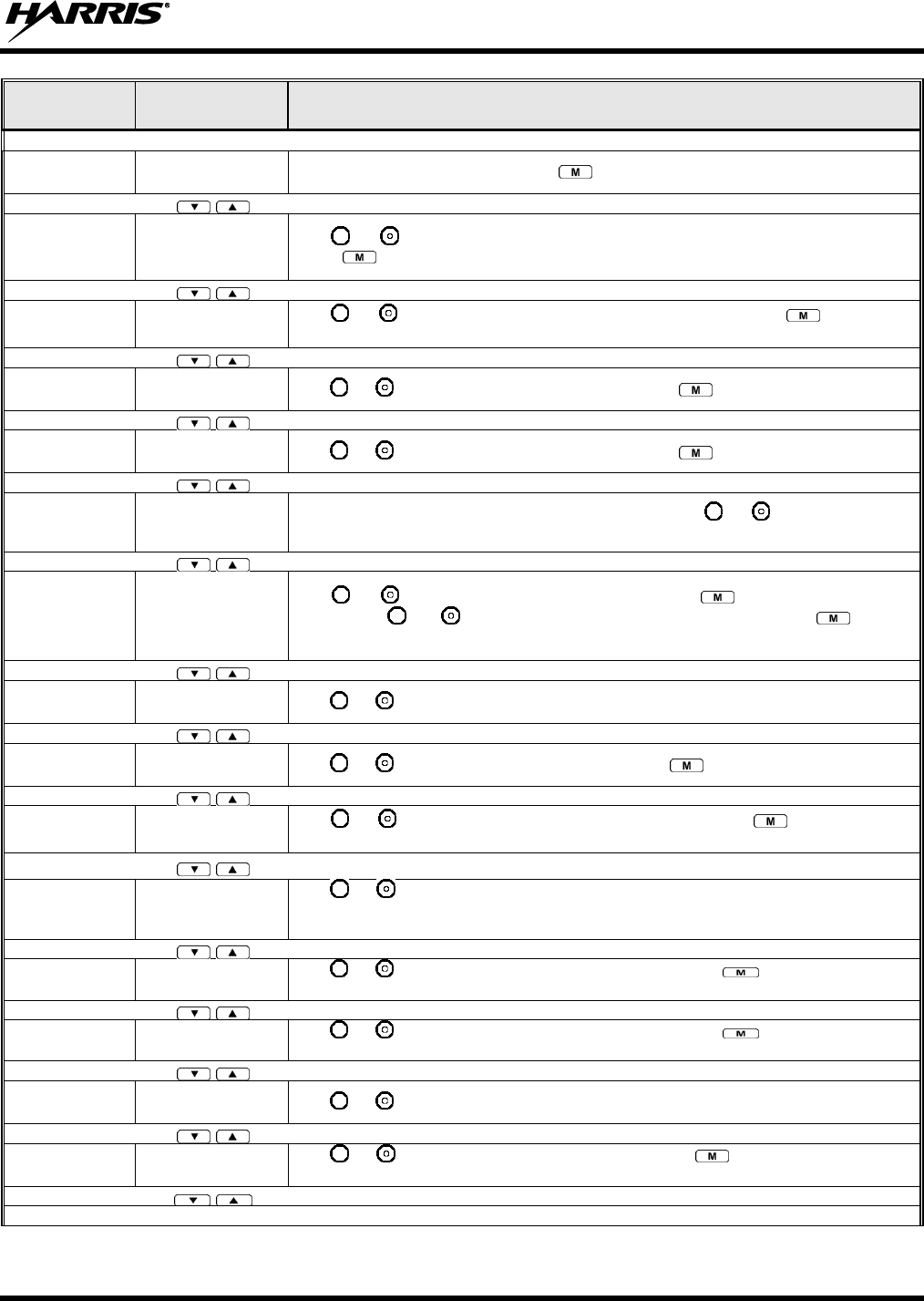
14221-1100-2010, Rev. E
41
MENU
NAME
RADIO
DISPLAYS
USAGE NOTES
See Previous Page
Selected
Channel
“ChannelMenu”
Displays the current channel. Press to return to dwell display.
Scan Mode
“ScnModeMenu”
Use or to scroll through available scan modes (Normal, No Scan, or Fixed).
Press to return to dwell display.
Talk group
Lock Out
“LockOutMenu”
Use or to choose a talk group for locking/unlocking. Press to toggle “<”
on (locked out) and off.
Priority 2
Talk group
“Priority2”
Use or to choose Priority 2 talk group. Press to return to dwell display.
Priority 1
Talk group
“Priority1”
Use or to choose Priority 1 talk group. Press to return to dwell display.
Alerts Received
“Alerts Rcvd”
or oldest message
“No alerts” or alert message text scrolls in display. Use or to scroll through all
messages.
Alert Destination
“Alert Dest”
Use or to choose a speed-dial number. Press to go to the “Alert Msg”
menu. Use or to scroll through “canned messages.” Press to send
message and return to dwell display.
Speed Dial
“Speed Dial”
Use or to choose a speed-dial number and press PTT to place call.
Profile Selection
“ProfileMenu”
Use or to choose an available profile. Press to return to dwell display.
Talk group
Selection
“TalkGrpMenu”
Use or to choose a talk group in current profile. Press to return to dwell
display.
Status LED
“Status LED”
Use or to toggle status led “On” or “Off.” When On, the LED flashes red when
the radio transmits, green when receiving, and amber when in emergency. When Off,
the LED will not light at all.
Status Message
“Status Msg”
Use or to scroll through available messages. Press to send the selected
message.
Request to Talk
Message
“RTT Msg”
Use or to scroll through available messages. Press to send the selected
message.
V-TAC Client
Mode
“Client Mode”
Use or to choose Client Mode (Network, XCOV, XCOV-TG, or SOI).
Emergency
Dismiss
“EmgDismiss”
Use or to choose emergency talk group. Press to toggle “<” on (dismiss)
and off.
See Next Page
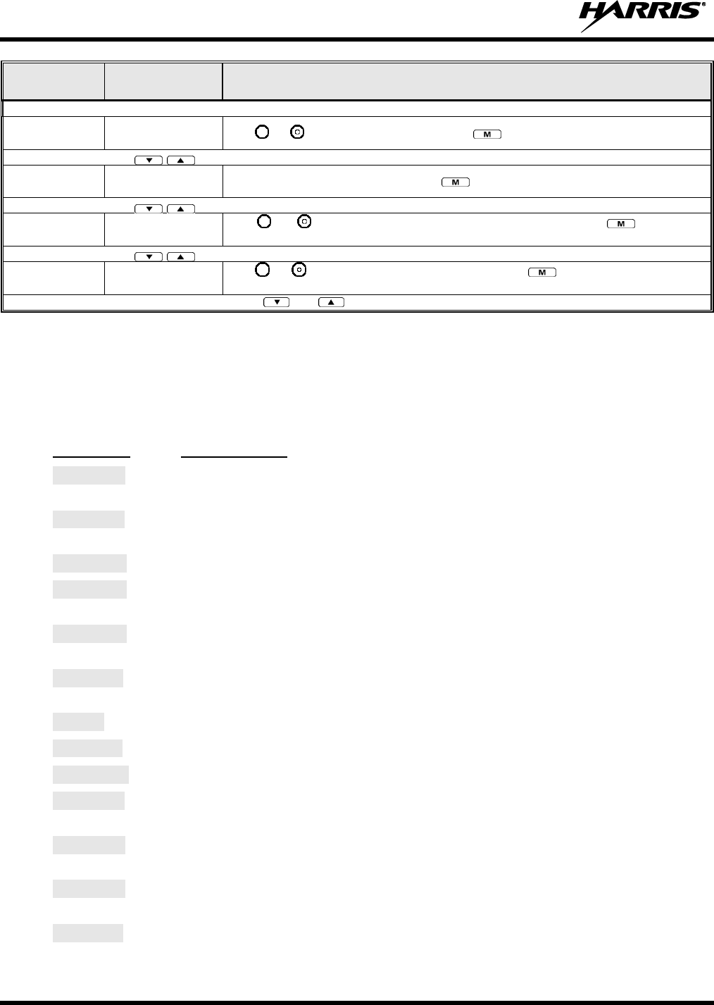
14221-1100-2010, Rev. E
42
MENU
NAME
RADIO
DISPLAYS
USAGE NOTES
See Previous Page
Site Lock
“Site Lock”
Use or to scroll through sites. Press to select site.
OTP Software
Version
“Software Ver”
Displays OTP software version Press to return to dwell display.
RF Diagnostics
“Diagnostics”
Use or to scroll through RF diagnostics displays. Press to reset RF
diagnostics counters.
Priority 3 Talk
Group
“Priority 3”
Use or to choose Priority 3 talk group. Press to toggle “<” on (selected)
and off.
Use and to scroll through menus.
8.9 ERROR MESSAGES
This section lists and describes the error messages that may be displayed by the radio during OpenSky
operation.
MESSAGE
DESCRIPTION
NOAUT01
Unspecified MDIS error. If condition persists in strong signal conditions, contact
your system administrator.
MDENIED
Unspecified MDIS error. If condition persists in strong signal conditions, contact
your system administrator.
UNAUTH3
Unauthorized IP. The radio network ID has not been added to network.
UNAUTH4
Bad authentication. If condition persists in strong signal conditions, contact your
system administrator.
UNAUTH5
Unsupported authentication. If condition persists in strong signal conditions, contact
your system administrator.
MDISBSY
The MDIS is busy. If condition persists in strong signal conditions, contact your
system administrator.
DUP IP
Duplicate IP.
BADIKEY
Invalid infrastructure public key sequence number (IPKSN).
BADEKEY
Invalid end-system public key sequence number (EPKSN).
UNK MES
Unknown mobile end system (MES). If condition persists in strong signal conditions,
contact your system administrator.
NOAUT05
MDIS failed mutual authentication. If condition persists in strong signal conditions,
contact your system administrator.
BADMDIS
MDIS failed mutual authentication. If condition persists in strong signal conditions,
contact your system administrator.
MDS BSY
MDIS busy – retry.

14221-1100-2010, Rev. E
43
MESSAGE
DESCRIPTION
UNK DOM
Unknown home domain. If condition persists in strong signal conditions, contact
your system administrator.
KEYSYNC
Mismatched key sequence number.
UNK ALG
Unknown/unsupported encryption algorithm.
BADSIZE
Unsupported MDIS key size.
NOAUT11
MES failed data mutual authentication. If condition persists in strong signal
conditions, contact your system administrator.
NOAUT12
No response from MDIS. If condition persists in strong signal conditions, contact
your system administrator.
NOREPLY
No SME response from MDIS. If condition persists in strong signal conditions,
contact your system administrator.
VDENIED
Unspecified VNIC error. If condition persists in strong signal conditions, contact
your system administrator.
BAD VID
Invalid voice user ID. Check User ID. If correct, contact your system administrator.
HOM DWN
The Home VNIC is down. Retry. If error continues, contact your system
administrator.
SRV BSY
The serving VNIC is busy (congested).
MAX USR
The maximum number of users are already registered with the specified user ID.
OpenSky allows one User ID to log onto the network using up to three different
radios. Use *0## command or power down one of the other radios to de-register the
radio.
NAS BSY
The system cannot provision MES because of an administrative process.
NOAUTHM
The MES failed voice mutual authentication. If a valid radio displays this error,
contact TAC (see Section 11.2).
NOSUPRT
The MES cannot support the required provision. If condition persists in strong signal
conditions, contact your system administrator.
NOAUTHV
VNIC does not support or failed mutual authentication. If condition persists in strong
signal conditions, contact your system administrator.
PLS LOGIN
Login with keypad.
BAD PWD
An invalid password has been entered. Verify the password and re-enter.
OVER_TEMP
The radio may be too hot. The radio will cease transmitting if it exceeds an
operational temperature threshold. Let the radio cool before attempting to transmit.
Report this failure to authorized technician.
No App
ECP mode is unavailable (not programmed).
NO PRIV
Missing required privilege.
NO SYNC
No forward-channel sync (weak or no coverage). If condition persists in strong signal
conditions, contact your system administrator.
Dead battery
Radio must shutdown because battery charge is critically low.

14221-1100-2010, Rev. E
44
MESSAGE
DESCRIPTION
NO REG
Not registered with MDIS, VNIC, or both.
DISABLED
Function disabled (e.g., function invalid in current context).
8.10 KEYPAD FUNCTION COMMANDS (SYSTEM MODEL ONLY)
To perform a command from the keypad, use the keypad commands in Table 8-6.
Table 8-6: Keypad Function Commands
COMMANDS
FUNCTION
*0
Log-off command: *0## (logs the user off the system). See Section 8.4 for additional information.
*1
Log-in command: *1<User ID> # <Password> ## (required for encryption). See Section 8.1.3 for
additional information.
*2
Status Message: *2 <0...9> #.
*4
Enter Scene of Incident Mode (SOI) on specified channel and band: *4#<Chan>#<Band>#
where Chan is the channel number that is being used as a SOI repeater and band is the number
assigned to each frequency band. For example, if Channel 25 800 MHz (band 0) is being used for
SOI, then enter *4#25#0#.
Exit SOI Mode with *40#.
*5
RTT Message: *5 <0...9> #.
*7
Initiate Selective Alert command: *7<Target ID>#[Choose Message]#. See Section 8.26 for
additional information.
*8
Radio-to-Radio Call command: *8<Selective call number>#(PTT to dial).
*9
Public Switched Telephone Network (PSTN) Call command: *9 <telephone number>#(PTT to
dial) See Section 8.27 for additional information.
*32
Begin Manual Encryption command: *32<Pre-determined Encryption Key>#
1-16 digit encryption key for 128 bit encryption; 17-32 digit encryption key for 256 bit encryption.
*33
End Manual Encryption command: *33#.
*61
Initiate XCOV Mode: Extended coverage for individual users.
*62
Initiate XCOV-TG Mode: Extended coverage for talk groups.
*63
Initiate XCOV-PROF Mode command: *63#.
*60
Exit XCOV or XCOV-TG Mode: Returns to the Network mode.
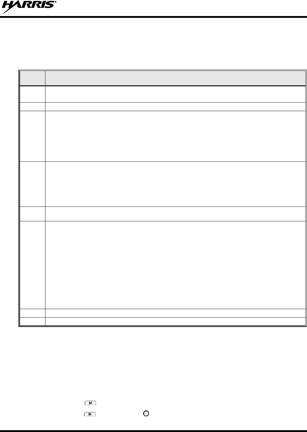
14221-1100-2010, Rev. E
45
8.11 QUICK KEYS (SYSTEM MODEL ONLY)
Quick Keys are a two-button sequence that provides the user with quick access to certain menu items.
Quick Keys function as a toggle for these menu items.
Table 8-7: Quick Key Sequence
QUICK
KEYS
FUNCTION
1#
Transition to ECP Mode
If ECP code is not loaded in the radio, “No App” appears in the display.
2#
Toggles Stealth Mode On/Off
3#
Toggles Scan Mode On/Off (Normal/Fixed, see details below)
If the Scan Mode is Normal when the Scan Mode is toggled Off, the Scan Mode will be Normal when
toggled On again.
If the Scan Mode is Fixed when the Scan Mode is toggled Off, the Scan Mode will be Fixed when
scan mode is toggled On again.
If the Scan Mode is Off when the radio boots up, the Scan Mode will be Normal when Scan Mode is
toggled On.
4#
Lights/Tones On/Off
Pressing 4# turns the TX/RX LEDs, Backlight, and Side Tones On/Off.
If any of the TX/RX LEDs, Backlight, and/or Side Tones are On, and this quick key sequence is used,
then all of the TX/RX LEDs, Backlight, and Side Tones are turned Off.
If the radio is in Stealth mode, this quick key is disabled since the user is not able to turn on the
light/tones in stealth mode.
5#
This quick key sequence is used to set the current active profile to the default profile in the personality as
defined in the UAS.
6#
XCOV & XCOV-TG Attach/Detach
This quick key sequence is used to manually connect to a V-TAC. When attaching to a V-TAC, the
radio’s programming determines whether to attach to the V-TAC in XCOV or XCOV-TG mode.
If the user attaches to a V-TAC manually, using the *61# or *62# command sequence, the radio is
understood to be attached and this quick key sequence will detach the radio from the V-TAC.
If the user detaches manually from a V-TAC using the *60# command sequence, the radio is
understood to be detached and this quick key sequence will attach the radio to a V-TAC.
At bootup, the radio is understood to be detached from a V-TAC. If a radio automatically attaches to
a V-TAC, the radio is still understood to be detached from a V-TAC and will attempt to attach to a V-
TAC.
If a radio manually attaches to a V-TAC and then is automatically detached from a V-TAC, the radio
will attempt to attach to another V-TAC.
7#
This quick key sequence is used to transmit the RTT Automatic Normal Message to the console.
8#
This quick key sequence is used to transmit the RTT Automatic Priority Message to the console.
8.12 DTMF OVERDIAL
Using the keypad on a System Model, the radio can transmit DTMF tones corresponding to
numbers/characters 0 - 9, *, and # on the keypad. To overdial numbers/characters, transmit by pressing
and holding the PTT button and then, press the corresponding keys (one at a time) on the keypad.
8.13 LOCK/UNLOCK THE KEYPAD
1. Press and hold the button.
2. While holding the button, press the button on the side of the radio.
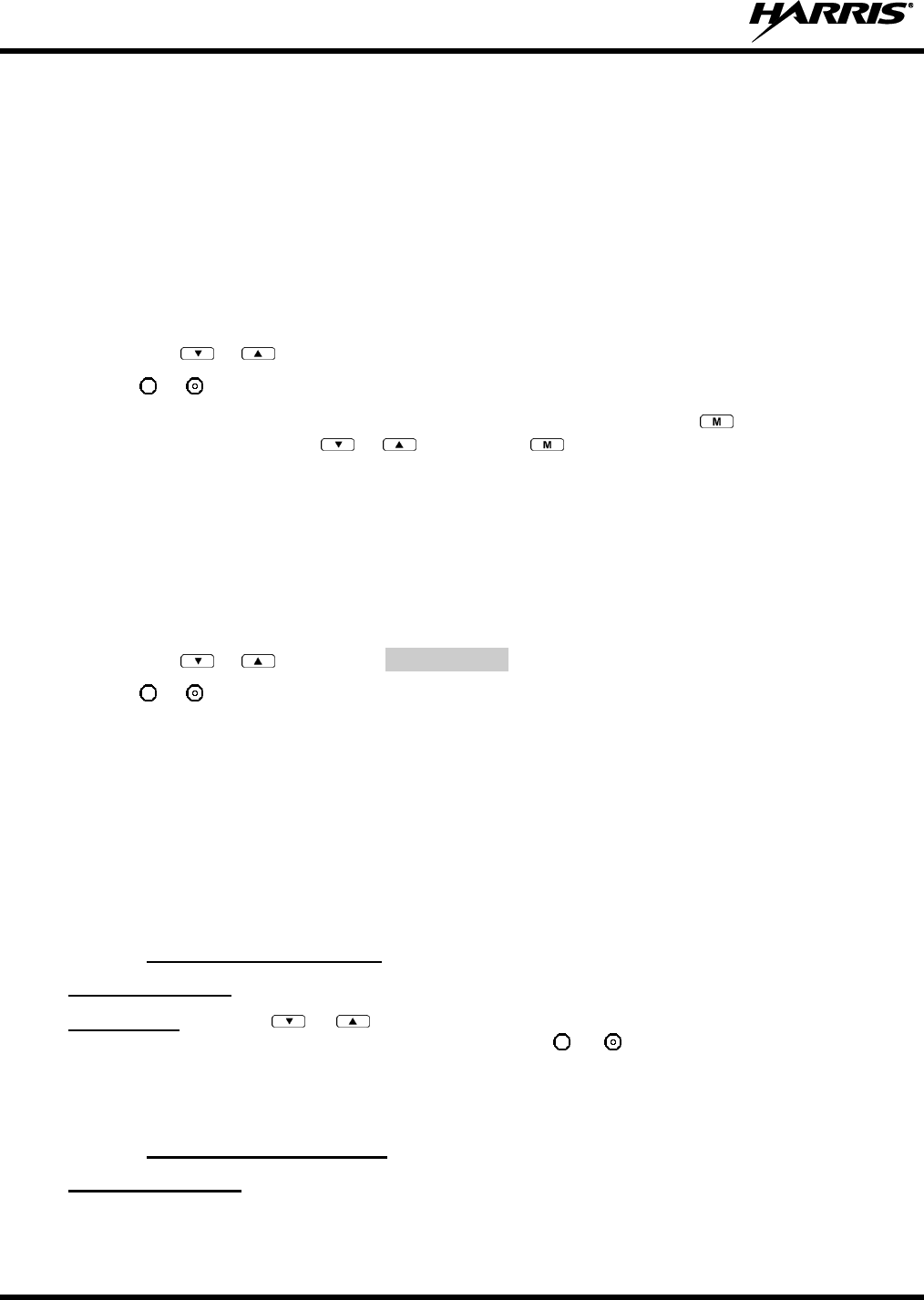
14221-1100-2010, Rev. E
46
8.14 DUAL-TONE MULTI-FREQUENCY (SYSTEM MODEL ONLY)
Dual-Tone Multi-Frequency (DTMF) is the system used by touch-tone telephones. DTMF assigns a
specific tone frequency to each key so a microprocessor can easily identify its activation. This allows for
specific tasks such as entering a user ID and password, or selective calling.
When a key on the DTMF keypad is pressed, the DTMF tone is played through the radio’s speaker.
8.15 CHANGING THE ACTIVE PROFILE
The radio can store up to 16 standard profiles, one of which is the currently active profile. To change the
currently active profile:
1. Press the or buttons until “ProfileMenu” is displayed.
2. Use or to scroll through the list of available profiles.
3. Profile becomes active when selected for longer than 2 seconds, when the is pressed, or when the
menu is changed using the or button. Press to activate the selected profile.
8.16 CHANGING THE SELECTED TALK GROUP
Each profile stored in the radio can have up to 16 talk groups. One talk group within the currently active
profile is set as the “selected talk group.” To change the selected talk group, turn the Group Selection
knob on top of the radio or use the Talk Group selection menu.
8.17 ADJUSTING DISPLAY AND BUTTON BACKLIGHT BRIGHTNESS
1. Press the or buttons until Bright Menu is displayed.
2. Use or to brighten or dim the display and button backlighting.
8.18 STEALTH MODE
For some users, it is important to be able to turn off the radio’s display lights and side tones, but not the
radio traffic. For example, in covert operations, lights and sounds could inadvertently expose an
otherwise unobservable radio user. For this purpose, the radio has a Stealth feature that disables the radio
display lights, indicator lights, audible alert, and side tones.
When Stealth Mode is on, the radio continues to scan the programmed list of talk groups and the user can
key-up on the selected talk group.
8.18.1 Enabling Stealth Mode
System Model only: Quick Key combination 2# toggles Stealth Mode on and off.
Both models: Press the or buttons to scroll through menus until “StealthMenu” appears in the
display. To immediately activate Stealth Mode press the or button once. This activates Stealth
Mode, exits the Stealth Menu, and returns to the Dwell Display.
The display lights, indicator lights, and side tones are disabled. The stealth mode icon is displayed.
8.18.2 Disabling Stealth Mode
System Model only: To re-enable all lighting, side tones and exit Stealth Mode, press Quick Key
combination 2# again. The radio returns to the Dwell Display.
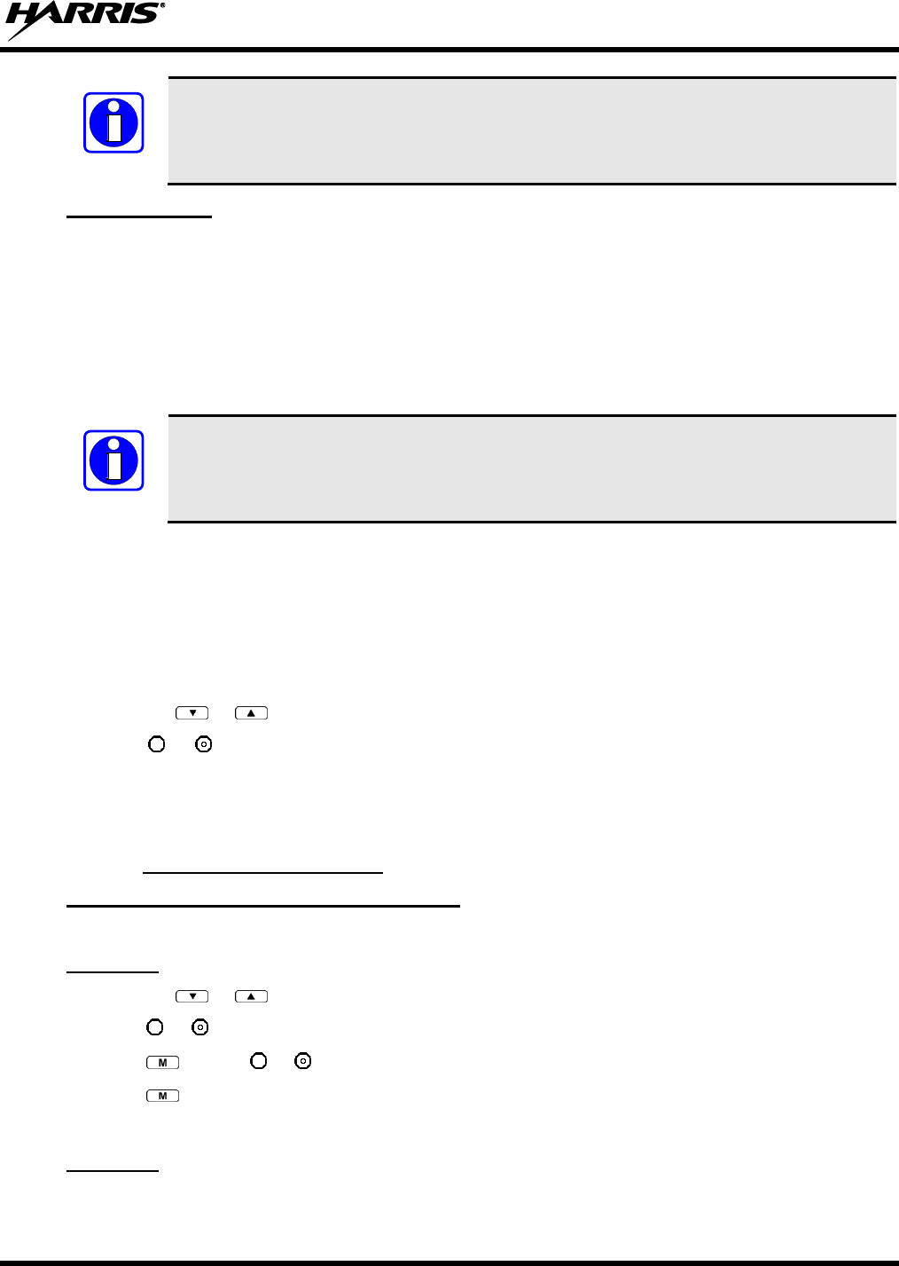
14221-1100-2010, Rev. E
47
Stealth Mode can also be disabled by using the Stealth Menu.
Scan Model only: To re-enable all lighting, side tones, and exit Stealth Mode, press any key other than
PTT or Emergency. The radio returns to the Dwell Display.
The display lights, indicator lights, and side tones are re-enabled. The stealth mode icon disappears.
8.19 ADJUSTING SIDE TONE AUDIO LEVEL
The radio sounds confirming tones called “side tones” when its buttons are pressed. Most users find this
audible confirmation helpful when navigating the menus. Side tone audio level can be adjusted or turned
completely off using the “Side Menu” or the Quick Key combination #4.
Quick Key combination 4# turns off the backlight in addition to the side tones. Unlike
Stealth Mode, alert tones can still be heard.
For covert operations, it may be necessary to turn off side tones. For safety’s sake, turning off the radio
during covert operations is not recommended.
If the radio is operating properly but side tones are not heard when the menu buttons are pressed, the side
tones are probably turned off. To turn them back on, access the “Side Tone” menu and select a setting
other than “off.”
Use the following procedure set side tone level:
1. Press the or buttons to cycle through the menu until “Side Menu” is displayed.
2. Press or to change to the desired level (Off, Low, Medium, and High). To turn side tones off
completely, use the “Off” setting.
8.20 CHANGE OPERATING MODE
8.20.1 From OTP to ECP Mode
Method 1 (Quick Key, System Model only):
Press 1#. If ECP is not loaded in the radio, the radio displays “No App.”
Method 2:
1. Press the or buttons to cycle through the menu until “App Mode” is displayed.
2. Press or to select the desired operation mode.
3. Press and use or to select Y or N.
4. Press to make selection and return to the dwell display.
5. “Restart Please Wait” appears in the display as the radio switches modes.
Method 3:
If configured, turn the A/B Switch to the A or B position.
NOTE
NOTE
14221-1100-2010, Rev. E
48
8.20.2 From ECP to OTP Mode
Press the or buttons to cycle through available systems until “OPEN SKY” appears in the
display. Pause briefly and the radio will switch automatically from ECP to OTP operation.
8.21 RECEIVING AND TRANSMITTING VOICE CALLS
As soon as the radio completes the initialization sequence and registers on the OpenSky network, the user
will begin to hear calls from the talk groups in the active profile, if available.
8.21.1 Receiving a Voice Call
No action is required to receive a voice call. The display responds to incoming voice calls as follows:
When the dwell display is set to received talk group and the scan mode is Normal or Fixed:
a. If the received talk group matches the selected talk group, then the alias (if available) or user ID
of the incoming caller is displayed.
b. If the received talk group does not match the selected talk group, then the received talk group
name is displayed.
When the dwell display is set to received talk group and the Scan Mode is None, the radio only
receives voice on its selected talk group. When the call is received, the alias (if available) or the user
ID of the incoming caller is displayed.
When the dwell display is not set to received talk group, then there is no display indication of an
incoming call.
A radio receiving a System All Call, Regency All Call, or an Agency All Call displays
“All Call” instead of the alias. A radio not transmitting on a talk group in emergency
status will drop all other calls to scan into an All Call.
8.21.2 Transmitting a Voice Call
1. Select the desired talk group.
2. Depress and hold the PTT button, wait a couple of seconds. If programmed by the administrator, a
grant tone will be sounded.
3. Begin speaking into the microphone in a normal voice.
4. For maximum clarity, hold the radio approximately 2 inches from your mouth. Take care not to cover
up the microphone while speaking.
5. Release the PTT button to terminate an outgoing voice call.
8.22 ADJUSTING AUDIO TREBLE LEVEL
The tone of received signals can be adjusted using the radio’s “Treble Menu.”
1. Press the or buttons to cycle through the menu until “Treble Menu” is displayed.
2. Press or to increase or decrease level. There are four levels available: low, medium, medium-
high, and high.
3. Press or wait a few seconds to return to the dwell display.
NOTE
14221-1100-2010, Rev. E
49
8.23 TALK GROUP LOCK OUT
There are two ways to focus voice communications by suppressing calls from talk groups in the active
profile.
No Scan. By changing the Scanning Mode to “No Scan” only the selected talk group is scanned.
Lock Out. By locking out selected talk groups, background noise or chatter can be eliminated, and
scanning resources can be focused on just those groups whose calls you wish to monitor.
Lock out is a listening (receive) function and only blocks received calls on locked out talk
groups. Lock out does not affect transmit capability. “No Scan” and “Lock Out” do not
apply to recent emergency lock outs.
Only talk groups in the active profile can be locked out, since they are the only talk groups whose voice
calls can be heard on the radio. Talk group lock out is a scan-related feature. With lock out, one or more
talk groups in the active profile can be temporarily disabled from being scanned. Calls are not received
on locked-out talk groups. Lock out settings are not retained between profile changes.
P1, P2, and P3 groups CANNOT be locked out.
The default emergency and emergency-capable talk groups can be locked out if they are NOT in an
emergency state. If a talk group is locked out and is subsequently changed to the currently selected talk
group, it will automatically be unlocked by the radio so the user can hear calls on the talk group. The
radio may be configured so all talk groups are automatically locked out by default. In this case, they must
be manually unlocked, if desired.
8.23.1 Lock Out a Talk Group
1. Use the or buttons to scroll through the menu choices until “LockOutMenu” appears in the
display.
2. Use the or keys to scroll through the list of talk groups, if any, until the user group you want to
lock out appears in the display.
3. Press the key to select the lockable talk group.
4. “<” appears next to the locked out talk group.
8.23.2 Unlock a Talk Group
1. Use the or buttons to scroll through the menu choices until “LockOutMenu” appears in the
display.
2. Use the or keys to scroll through the list of talk groups, if any, until the user group you want to
unlock appears in the display.
3. Use the key to unlock the displayed talk group.
Changing the active profile removes any lockouts you have made.
Turning off the radio removes any lockouts you have made.
NOTE
NOTE
NOTE
14221-1100-2010, Rev. E
50
8.24 SCANNING
8.24.1 Selecting Scan Modes
Three scanning modes are available for the radio, but only one can be active at any time. Changing the
scanning mode changes the way the radio scans voice calls for all of the profiles in the radio personality,
no matter which profile is or becomes active.
The choice of scanning mode broadens or narrows the span of communications with all the groups in
profiles you listen to, but does not affect your interaction with those groups you talk with. The scanning
modes available for selection may be limited to a subset of the three scanning modes by the administrator.
Table 8-8: Scan Modes
SCAN
MODE
EXPLANATION
None
Eliminates distractions.
Full communications (listen and talk) with the selected talk group.
No calls received from other talk groups.
Normal
(Default)
The user can scan all talk groups in the active profile that are not locked out as long as there is demand on
the site.
Priority (P1, P2, and P3) groups are user selectable.
Receive calls from more than one talk group, if available from the current site.
Allows dragging of the selected talk group, P1, P2, P3, and emergency talk group (in emergency state) to the
site on which the radio is registered. (If other calls are available at the site, they also can be heard but they will
not be actively dragged.)
The default emergency talk group, as well as any emergency-enabled talk groups, is only dragged if it is in
emergency mode.
Fixed
Functions the same as Normal Scan Mode, except the priority groups are fixed to the selected profile’s pre-
defined P1 and P2 groups (configured via the UAS).
The scanning mode choice remains in effect until it is changed. Even if the radio is turned off, the current
scanning mode selection is saved for the next use.
8.24.2 Changing Active Scan Mode
8.24.2.1 Setting the Scan Mode
1. Press the or buttons until “ScnModeMenu” appears in the display.
2. Use the or keys to scroll through the list of modes until your choice appears: Normal, None, or
Fixed.
3. Press the key to activate the scan mode selection and return to the dwell display.
8.24.2.2 Duration of Scanning Mode Selections
Scanning Mode selections survive power down. At startup, the radio defaults to the scanning mode of set
during last use. The last selection made remains in effect until a new selection is made from the Scan
Mode menu.
8.24.3 Scanning Priority
The following lists the scanning priority order (from highest to lowest):
Selected talk group in emergency state.
14221-1100-2010, Rev. E
51
Default emergency group in emergency state.
Selected talk group.
Emergency capable group in emergency state.
Priority 1 talk group.
Priority 2 talk group.
Priority 3 talk group.
Other (non-priority).
8.24.3.1 Changing Scan Priority
1. Press the or keys until “Priority1” or “Priority2” appears in the display (Priority1 group has
higher priority than the Priority2 group).
2. Press the or button until the desired talk group is displayed.
3. Press the key to select and activate the selection. The radio automatically returns to the Dwell
Display.
Changing the priority of a listen group does not change your talk group.
Priority can be set for six talk groups (Priority1, Priority2, and up to four Priority 3),
but only in the selected profile.
If the save settings is configured for the radio, scanning priority settings are saved
when the radio is turned off. Otherwise, they are reset to the default values when the
radio is turned off.
8.24.3.2 Changing Scan Priority 3 Talk Groups
1. Use the or buttons to scroll through the menu choices until “Priority 3” appears in the
display.
2. Use the or keys to scroll through the list of talk groups, if any, until the user group you want to
set as Priority 3 appears in the display.
3. Press the key to select a Priority 3 talk group.
4. “<” appears next to the Priority 3 talk group.
8.24.4 Scan Mode A/B Switch
The A/B switch can be configured to toggle Scan Mode On/Off.
If the Scan mode icon (see Table 8-3) is On; either the Normal or Fixed Scan modes are enabled,
depending on programming. If the Scan mode icon is not displayed, Scan mode is set to No Scan.
NOTE
14221-1100-2010, Rev. E
52
8.24.5 Scan Mode Quick Key (System Model Only)
Press 3# to toggle Scan mode on and off.
If the Scan mode icon (see Table 8-3) is On; either the Normal or Fixed Scan modes are enabled,
depending on programming. If the Scan mode icon is not displayed, Scan mode is set to No Scan.
8.25 MAKING SELECTIVE CALLS
Selective calling is the capability for two voice radio units to obtain and use an independent talk path for a
unit-to-unit call. A properly equipped radio can initiate a selective call to any radio in the system that is
also programmed for selective calls.
In the OpenSky system, a radio can be configured to initiate selective calls through a pre-programmed list
in memory called a speed dial list. Alternatively, a properly equipped radio can initiate a selective call to
any radio in the system by entering the ten-digit User ID (similar to a telephone number) of the target
radio. Some radios are configured to only receive (not initiate) selective calls.
Selective calls are terminated if an emergency is declared. The network limits selective
calls to ten (10) minutes maximum.
If a Selective Call is attempted without registration, “No Priv” is displayed.
8.25.1 Manually Dialing a Selective Call (System Model Only)
1. Enter *8, the User ID number of the user being called, and the # key (no dashes or spaces). This
feature must be enabled by the administrator.
*8<destination user id>#
A shortened User ID number can be dialed using the following guidelines:
If the radio being called is in the same region and agency – enter only the last four digits.
If the radio being called is in the same region, but a different agency – enter only the last seven
digits.
If the radio being called is in another region or if the area is unknown – enter all ten digits.
2. Press the PTT (and release) to ring the other user.
The ring tone is sounded.
If the other user accepts the call, the called user’s alias will appear in initiating caller’s display. The
two are now in a unit-to-unit call until one ends the call, the call is terminated due to an initiated
emergency, or the maximum time limit of ten (10) minutes is reached.
If the called radio is busy, “BUSY” will appear in the second line of the display.
Table 8-9 lists and defines the messages that are displayed by the radio during a selective call.
NOTE
NOTE
14221-1100-2010, Rev. E
53
Table 8-9: Status of Selective Call
STATUS
MESSAGE
DEFINITION
Busy
Peer is involved in another selective/PSTN call.
Disconnect
Selective/PSTN call was terminated for unknown reason.
Network Err
Selective/PSTN call cannot continue because of an unspecified network error.
Reject
Peer or this user declined request to establish selective/PSTN call.
Unavailable
Peer cannot be reached for selective/PSTN call.
Calling
Calling peer (i.e., for selective or PSTN calls).
Connecting
Establishing selective/PSTN call with peer.
Hangup
Peer or this user terminated selective/PSTN call.
Lim 10 min
Selective/PSTN call limited to 10 minutes.
Timing Out
Selective/PSTN call has 10 seconds remaining before limit is reached (shown for 5 seconds).
Sel Call
Selective call is active.
8.25.2 Selective Call Using Speed Dial
Speed dial numbers are defined and provisioned by the OpenSky network administrator and
cannot be manually entered into the radio by the user. Contact the administrator if changes
to the speed dial list are required.
Scroll through the Menu options using the or button until “Speed Dial” appears in the
second line of the display. Using the or keys, scroll through the pre-programmed speed-dial
numbers until the desired number appears in the display and press the PTT button.
OR
Press and hold a key associated with a given number for more than three seconds. For example, press
and hold the to open the Speed Dial Menu and display the number assigned to that key in the
speed dial list. Press the PTT button.
A ring tone is sounded.
If the other user accepts the call, the called user’s alias will appear in initiating caller’s display. The two
are now in a unit-to-unit call until one ends the call, or the call is terminated due to an initiated
emergency.
If the called radio is involved in another selective call, “BUSY” will appear on the second line of the
display. “Unavailable” is displayed when the call has not been answered after a 1 minute timeout or
when the other party is not registered on the network.
8.25.3 Accepting a Selective Call
1. The radio will ring (like a telephone), indicating you are receiving a Selective Call.
2. Press , , or buttons to accept the incoming Selective Call.
3. “CONNECT” appears in the display, followed by “Lim 10 Min.,” “SEL CALL,” and the alias of the
caller, once the call is established.
8.25.4 Rejecting a Selective Call
When a Selective Call is received (the radio is ringing), you can reject the call by pressing or .
The call is rejected and “Reject” appears on the callers display.
NOTE

14221-1100-2010, Rev. E
54
8.25.5 Terminating a Selective Call
Terminate a Selective Call (call must be active) by pressing the or button. “HANGUP” will
appear in the display followed by the active talk group.
8.26 SELECTIVE ALERTS
Selective alert messaging is an OTP feature that allows one of up to eight (8) pre-programmed (canned)
text messages to be sent from one radio to another. The sender specifies a destination (receiving) radio,
selects one of the pre-programmed text messages, and then transmits it to the destination radio. The
message delivery system adds sender and time-of-day information and forwards the message to the
destination (receiving) radio. The sending radio receives a brief message noting the status of the
transmission.
Received messages are stored in the radio until deleted or until the radio is rebooted. Received messages
do not survive a reboot.
8.26.1 Defining Messages
All selective alert messages are pre-defined. The messages are programmed and provisioned remotely by
your OpenSky system administrator. The radio user cannot create selective alert message content. The
entire selective alert message, including the abbreviation, can be up to 99 characters long.
Table 8-10 lists and defines the messages that may be displayed by the radio during a Selective Alert.
Table 8-10: Status of Selective Alert Messages
STATUS
MESSAGE
DEFINITION
Alert Sent
Alert message successfully sent to target.
Delivered
Alert message passed to network.
Delivering
Delivering alert message to target.
New alert
New alert message received.
No alerts
No alerts are available.
Busy
VNIC congested and cannot deliver message at the current time.
Dest Down
Destination home VNIC down.
Ignored
Destination is either non-responsive or does not care to respond.
Inv Option
Distribution option is invalid.
Not Reg
Destination is not registered.
Partial
Not all destination ESN instances reachable.
Unauth Alrt
Unauthorized service function; initiator is not authorized to send the selected service message.
Unknown Msg
Unknown status received from VNIC.
Unreachable
Alert destination cannot be reached.
8.26.2 Sending a Message
The sending process has three steps. First select the destination radio’s User ID, then select the alert
message, and finally send the message. Refer to the procedures in subsections 8.26.2.1 or 8.26.2.2 for
instructions on selecting a destination for a Selective Alert Message.
14221-1100-2010, Rev. E
55
8.26.2.1 Selecting a Destination Using the Keypad (System Model Only)
1. Using the keypad, enter *7.
At the “AlertDst” prompt, enter the full User ID of the unit to send the message. A shortened User
ID number can be dialed using the following guidelines:
If the radio being called is in the same region and agency – enter only the last four digits.
If the radio being called is in the same region, but a different agency – enter only the last seven
digits.
If the radio being called is in another region or if the area is unknown – enter all ten digits.
2. Press the key to activate the selection.
3. Use the and buttons, or the and buttons to scroll through the available messages until
the desired message is displayed.
4. Press the or key to send the message.
5. Observe Status Messages (Table 8-10) to ensure proper delivery.
8.26.2.2 Selecting a Destination Using the Menu
1. Using the or key, scroll through the menu until “AlertDst” (Alert Destination) appears.
2. Use the or button to scroll through the list of User IDs until the desired destination is displayed
and press the key.
3. Use the or buttons to scroll through the available messages until the desired message is
displayed.
4. Press the key to send the message.
5. Observe Status Messages (Table 8-10) to ensure proper delivery.
8.26.3 Receiving a Message
When a selective alert message is received by a radio, a four-beep tone is heard. The tone is heard only
once, but the message “NEWALRT” alternates with the talk group on the main display. Up to eight
received messages can be stored. If a ninth message is received, the first (oldest) message is automatically
deleted to make room for the new message.
Received messages are displayed with the time and source information.
To display a Selective Alert Message:
1. Using the or button, scroll through the menu items until “Alerts Rcvd” appears. The oldest
message is displayed and scrolls across the top line of the display.
2. The message includes the time, the User ID, and alias of the sender along with the message.
3. To view the next message, press or .
8.26.4 Deleting a Selective Alert Message
1. Display the message.
2. Press the key and or to select Y or N.
3. At the “Delete? Y” prompt, press the key. The message will be deleted.
14221-1100-2010, Rev. E
56
Received messages cannot be saved.
8.27 MAKING INTERCONNECT CALLS (SYSTEM MODEL ONLY)
1. Using the keypad, enter *9, followed by the telephone number being called, and the # key (no dashes
or spaces).
*9<telephone number>#
Wait a couple of seconds and press and release the PTT button to initiate the call. An initial ring tone
will sound to indicate signal call initiation. Once the gateway picks up the call, the ring tone will
change. Press and hold the PTT and talk normally then release the PTT to listen.
2. To hang up the call, press or the key.
8.28 EMERGENCY COMMUNICATIONS
The XG-75P portable radio is capable of sending an emergency alert and making emergency calls on the
network. The OpenSky system handles emergency calls with the highest priority, allowing you or the
people you serve to get needed help.
Emergency call and alert capability for a profile is configured by the system administrator.
The radio that initiates an emergency alert emits a signal of three distinct beeps that only
goes to the dispatch console.
Table 8-11: Emergency Calls vs. Emergency Alerts
EMERGENCY ALERT
EMERGENCY CALL
An Emergency Alert message is sent to
the dispatcher console. The dispatch
console plays an emergency tone when it
receives the message.
An Emergency Alert message is sent to the dispatcher console. All peers
(radios and consoles) and the dispatch console play the emergency tone
whenever an emergency call is detected. An emergency tone plays for each
new emergency, or when a profile is changed, (assuming there is an
emergency on one of the talk groups for the new profile).
If the orange LED is flashing rapidly, the radio is receiving an emergency
call. If the LED is flashing every ½ second, the selected talk group is in the
emergency state (although not transmitting). If the selected talk group is in
the emergency state, an asterisk displays next to the talk group name.
No emergency audio (voice) transmission
(hot-mic) capability available (per
programming by system administrator)
In addition to the Emergency Alert signal, the microphone goes hot for a
predetermined length of time to allow for emergency audio (voice)
transmission. The radio declaring the emergency has channel access
priority. The User can also use the PTT after the pre-determined hot-mic
audio transmission, or during to extend the initial hot-mic audio transmission.
NOTE
NOTE

14221-1100-2010, Rev. E
57
8.28.1 Declaring an Emergency Call or Alert
1. Press the red emergency button on the radio to enter emergency mode.
The emergency behavior for the selected profile is configured by the network
administrator. This determines whether pressing the Emergency button sends an
Emergency Call or just an Emergency Alert. An Emergency Alert is always part of and
sent with an Emergency Call.
If the active profile of the unit initiating the emergency is configured to Emergency Alert, the three-
beep emergency alert signal is sent only to the dispatcher console.
If the active profile of the unit initiating the emergency is configured to Emergency Call, the three-
beep emergency alert signal is sent to the dispatcher console and to all other radios within the selected
talk group. The default emergency talk group becomes the selected talk group. The display will
alternate between the emergency talk group name and “EMERGENCY” to indicate that the
emergency has been initiated.
2. The microphone is hot (open mic) for a programmed amount of time in order to send your voice out
on the emergency talk group.
If the attempt is unsuccessful, “E-PEND” flashes periodically and a retry is queued for 10 seconds. If
unsuccessful because of lost sync, retry occurs immediately upon reacquiring sync. On each retry attempt,
the radio temporarily displays “E-RETRY.” This process repeats until the emergency is successfully
declared.
8.28.2 Receiving an Emergency Call
When receiving an emergency call, the radio sounds the emergency tone (three short high-pitched tones).
The radio will flash “EMERGENCY” and display the alias of the user that triggered the emergency or the
alias of the talk group (if the incoming talk group is the selected talk group of the receiving radio).
With “No Scan,” only the emergency tone is heard, not the initial open mic transmission.
To dismiss or ignore the emergency, refer to Section 8.28.3.
8.28.3 Dismissing an Emergency
The “Dismissing an Emergency” function allows you to “ignore” an emergency declared by another user.
An emergency is dismissed for a configurable amount of time (default = 5 minutes).
1. After receiving an emergency call, press the or button until you see “EmgDismiss.”
2. Press the to toggle “<” on (dismiss) and off. This works in similar fashion to the lock out menu.
The emergency dismiss timer is cleared when the emergency is cleared.
NOTE
NOTE
NOTE
14221-1100-2010, Rev. E
58
8.28.4 Clearing an Emergency Call or Alert
Check with your system administrator to ensure that your radio is configured with the
ability to clear an emergency.
1. To clear an emergency, press and hold . While holding , press the emergency button. Release
both buttons when the “emergency cleared” tone sounds.
2. The radio returns to your default selected talk group. The “EMERGENCY” display is removed from
the main screen.
If the radio is in stealth mode, clearing the emergency will cause the radio to exit stealth
mode.
8.29 OPENSKY ENCRYPTION
In the OpenSky network, both data and voice use a 128-bit or 256-bit key encryption standard published
by the Federal Information Processing Service (FIPS), called Advanced Encryption Standard (AES).
AES is approved by the U.S. Department of Commerce for encryption of classified materials.
When encryption is enabled on the network, data is encrypted from the MDIS to the Mobile End System
(MES) (e.g., XG-75P portable radio). This form of encryption provides airlink security.
Voice encryption is handled either automatically or manually. Automatic encryption is initiated through
the Unified Administration Server (UAS) for a specific talk group and requires nothing from the radio
user. Manual encryption is initiated by two or more radio users. Both methods of encryption are
discussed in the following sections.
When a user transmits encrypted voice, any listening users with different encryption keys
hear distorted voice and “No Access” appears in the radio display.
8.29.1 Automatic Encryption
For automatic encryption, a system administrator will select the talk group to be encrypted at the interface
to the UAS. Once the talk groups have been selected and identified as secure, credentials for key
generation are generated automatically by the system and provisioned to authorized users. This process
requires that authorized users login to the network and be authenticated. Encryption keys require no
manual handling and are never sent “in the clear” over any network interface or airlink.
1. Locate the talk group that has been encrypted at the system administrator level.
2. “Pls Login” appears in the display (unless the keypad was used to log in).
3. Log in normally by entering your User ID and Password.
If a user is engaged in a call on a talk group encrypted at the network administrator level, “Secure Call”
will appear in the second line of the dwell display if the user is logged into that talk group.
If a secure call is in progress elsewhere and the user has not logged in, the bottom of the dwell display
will alternate between “No Access” and the alias of the radio that is currently engaged in the secure call.
NOTE
NOTE
NOTE
14221-1100-2010, Rev. E
59
If enabled via programming, a radio can automatically login at voice registration and enable
voice encryption.
8.29.2 A/B Switch
If configured, the A/B switch can be used to enable or disable encryption.
8.29.3 Manual Encryption (System Model Only)
Two or more users can manually encrypt a call, if enabled, without an established encrypted talk group.
A pre-determined “key or code” is required. While a user is engaged in a manually encrypted call, users
within the talk group that are not encrypted can still make standard voice calls on that talk group. The
encrypted user can hear the standard unencrypted calls, but cannot respond while still manually
encrypted.
Manual key entry only affects the currently selected talk group. All available talk groups within the
current profile may be independently encrypted.
The key must be pre-determined by the users prior to making a manually encrypted call on
a talk group and is entered into the radio using the keypad. For 128 bit encryption, this
key is between 1 and 16 digits. For 256 bit encryption, this key is between 17 and 32
digits.
8.29.3.1 Using Manual Encryption
1. Press *32 on the keypad.
2. Enter the key (1 – 16 digits for 128 bit encryption; 17 – 32 digits for 256 bit encryption).
3. Press #.
4. To end manual encryption, press *33.
If a user is engaged in a call on a talk group that has been manually encrypted at the radio level, the user
will see “Secure Call” on the bottom of the dwell display.
If a secure (encrypted) call is in progress, and the user has not entered the key, the bottom of the dwell
display will alternate between “No Access” and the alias of the radio that is currently engaged in the
secure call.
Once the user has terminated manual encryption, “UnSecure” appears temporarily in the bottom line of
the dwell display.
8.30 STATUS MESSAGES
If enabled via programming, the radio can transmit a pre-programmed status message. Section 8.30.1
describes how to send a status message via the keypad and Section 8.30.2 describes how to send a status
message via the menu.
8.30.1 Send Status Message via the Keypad (System Model Radios Only)
1. Press *2 <0…9> # on the keypad.
2. A Status message can be associated with each key (0 – 9). This text is displayed on the first line of the
display when the key is pressed until another key is pressed.
NOTE
NOTE

14221-1100-2010, Rev. E
60
If no messages have been configured, “No Messages” is displayed.
If a message is not assigned to a key, “No Entry” is displayed for the keypad sequence.
You can press multiple keys to select the desired Status message.
3. The # key terminates the keypad sequence and sends the currently selected status message. If no
messages have been configured or no message is associated with the key, no message is sent and an
error tone is played.
Press the * key to cancel the keypad sequence.
8.30.2 Send Status Message via the Menu
1. Press or until “Status Msg” appears and press . If no messages have been configured,
“No Messages” is displayed.
2. Scroll through the available messages using or . The configured Status message is displayed on
the 1st line of the display.
3. Press the button to send the currently selected message. If no messages have been configured, no
message is sent and an error tone sounds.
Press or to cancel status message selection.
8.31 REQUEST TO TALK (RTT) MESSAGES
If enabled via programming, the RTT message feature allows you to send a short service message to the
VNIC. Section 8.31.1 describes how to send an RTT message via the keypad and Section 8.31.2 describes
how to send an RTT message via the menu. Only one RTT message can be programmed into the radio.
8.31.1 Send RTT Message via the Keypad (System Model Radios Only)
1. Press *5 <0…9> # on the keypad. The key associated with the RTT message (0-9) is configured via
programming.
2. This message is displayed on the first line of the display when the key is pressed until another key is
pressed.
If no message has been configured, “No Message” is displayed.
If a message is not assigned to the key, “No Entry” is displayed for the keypad sequence.
3. The # key terminates the keypad sequence and sends the currently selected RTT message. If no
message has been configured or no message is associated with the key, no message is sent and an
error tone is played.
Press the * key to cancel the keypad sequence.
8.31.2 Send RTT Message via the Menu
1. Press or until “RTT Msg” appears and press . If no message has been configured, “No
Message” is displayed.
2. Use or to select the message. The configured RTT message is displayed on the 1st line of the
display.
3. Press the button to send the selected message. If no message has been configured, no message is
sent and an error tone sounds.
Press or to cancel RTT message selection.
14221-1100-2010, Rev. E
61
8.32 SITE LOCK
Users may need to select the site in cases where network communications are down. The Site Lock menu
allows a user to manually roam to a specific site. The sites in the menu are populated with the current
site, adjacent sites, and node 2 sites. The menu allows the user to select a particular site based on the Site
Name. Once selected, the radio will randomly pick a channel at the site that is identified as operational
and attempt to attach to it.
If the channel is not available, the radio attempts to attach to the next channel in the channel list for the
site until it has attempted every channel at the site. If no channels are available, the radio plays a “Site
Not Found” tone and displays “SiteUnavail” on the second line of the Site Lock menu. The radio reverts
to its normal roaming functionality.
If the radio does find a valid channel on the site, it attaches to it, plays a “Site Found” tone, displays
“SiteAvail” on the second line of the Site Lock menu for 2 seconds, and then reverts to the Dwell menu
8.33 GPS COORDINATES
The radio’s current latitude and longitude coordinates may be displayed using the “GPS” menu. The
following procedure assumes a GPS antenna is connected to the radio and it is receiving adequate signals
from GPS satellites.
1. Press or until the “GPS” menu appears in the display. Current GPS coordinate latitude and
longitude data continuously scrolls in the top line of the display in a degrees:minutes:seconds format.
2. Press or to change to another menu.
If the internal GPS receiver’s data is expired (30 minutes or more) or unavailable, the
radio uses the serving base station’s coordinates [GPS (Site) is displayed]. The GPS
Menu will also indicate if the data is aged (2 minutes or more) [GPS (Aged) is displayed].
8.34 V-TAC OPERATION
8.34.1 Extended Coverage Modes (XCOV, XCOV-TG, and XCOV-PROF)
In addition to all standard portable radio operating capabilities, Extended Coverage adds the V-TAC’s
bridging (vehicular repeat) functionality for accessing the OpenSky radio network. Each portable radio
connected to the V-TAC using Extended Coverage is considered a “client” on the V-TAC. Extended
Coverage benefits portable radio users since it allows them to get network connectivity using the
V-TAC’s higher transmit output power and better antenna system.
The V-TAC supports three Extended Coverage modes: Extended Coverage for individual users (XCOV),
Extended Coverage for a talk group (XCOV-TG), and Profile Extended Coverage (XCOV-PROF).
Typically, Extended Coverage is used after the vehicle’s operator has exited the vehicle with a portable
radio unit and the portable unit requires this bridging functionality to access the OpenSky radio network.
The V-TAC takes advantage of OpenSky’s TDMA capability to eliminate interference between its local
and network radio links when operating in an Extended Coverage mode, an undesirable characteristic of
many traditional vehicular repeater systems. Because the V-TAC employs this technology, interference
on the network and local radio links is minimized.
A V-TAC in Extended Coverage mode sends its alias to clients. The alias is displayed in the second line
of the dwell menu of the client, (“VA <alias>”). The client must be connected to a V-TAC running
NOTE

14221-1100-2010, Rev. E
62
version OTP14.4 or later for the V-TAC to provide the alias to the client. If the client is connected to a V-
TAC running version OTP14.3.1 or earlier, the client displays “VA None.”
8.34.2 Change Between Extended Coverage Modes
By default, the specific Extended Coverage mode utilized is determined by settings programmed into the
V-TAC and portable radios from the system administrator or radio installation personnel. These
programmed settings determine which Extended Coverage mode the V-TAC and radios normally use and
determine the access method employed by a portable radio to connect to the V-TAC. After these settings
are programmed to the V-TAC and portable radios, each must be rebooted (powered off and then back
on) before the change takes effect.
See the following sections for instructions on how to override this setting manually. The override is only
successful if the V-TAC operating mode matches the manually selected portable V-TAC mode.
8.34.3 Radio Limitations Using Extended Coverage Modes
Connecting a portable radio to a V-TAC introduces minor functional limitations. See the following
sections for a listing.
8.34.3.1 Limitations Using XCOV, XCOV-TG, and XCOV-PROF
Portable radios connected to the V-TAC using any of the Extended Coverage Modes, XCOV, XCOV-TG,
or XCOV-PROF, will not channel-scan unless they lose radio frequency contact with the V-TAC. If
manually enabled, radios will not scan network channels.
8.34.3.2 Limitations Using XCOV-TG
The following portable radio keypad functions are disabled when the radio is connected to the V-TAC
using the XCOV-TG mode: log-off, manual log-in, alerts, selective calls, PSTN calls, and speed dial
calls, SOI mode, RTT.
The following portable radio menus are disabled when the radio is connected to the V-TAC using the
XCOV-TG mode: alert destination, alert message, alert received, channel, speed dial, priority 1 talk
group, priority 2 talk group, priority 3 talk group, RTT, Status message, site lock and scan mode. In
addition, the user cannot change talk group or profile.
8.34.3.3 Limitations Using XCOV-PROF
The following portable radio keypad functions are disabled when the radio is connected to the V-TAC
using the XCOV-PROF mode: log-off, manual log-in, alerts, selective calls, PSTN calls, and speed dial
calls, SOI mode, RTT.
The following portable radio menus are disabled when the radio is connected to the V-TAC using the
XCOV-TG mode: alert destination, alert message, alert received, priority 1 talk group, priority 2 talk
group, priority 3 talk group and scan mode. In addition, the user cannot change talk group or profile.
8.34.4 Use XCOV Mode
The Extended Coverage for individual users (XCOV) mode allows up to eight (8) client radios to connect
to the V-TAC. The radios have full radio functionality including selective calling and mobile data.
With the Extended Coverage for individual users’ (XCOV) mode, V-TAC configuration defines which
portable radios are permitted V-TAC access. The radio will automatically connect to a V-TAC if it
cannot find a network channel. The radio can also be manually connected to a V-TAC as indicated with
the *61# and *62# commands, each determined by the system administrator in the radio configuration.
14221-1100-2010, Rev. E
63
8.34.4.1 Manually Accessing the XCOV Mode
System Model Radios
1. Press *61# to manually access XCOV mode.
2. Press *60# to manually disconnect from XCOV mode.
Both Model Radios
1. Press or until the Client Mode menu appears.
2. Press or until XCOV is displayed.
3. Press to confirm mode selection. The radio reverts to the dwell display and the V-TAC icon is
displayed.
8.34.5 Use XCOV-TG Mode
When using the XCOV-TG mode, up to thirty (30) client radios can connect to the V-TAC. However,
unlike XCOV, radios connected using XCOV-TG are limited to communicating only on the XCOV-TG
talk group. The radio can only raise an emergency if this talk group is emergency capable. Advanced
features such as selective calling and mobile data operations are not available to the XCOV-TG connected
clients. The radio will automatically connect to a V-TAC if it cannot find a network channel.
The talk group used for XCOV-TG communications is the talk group that was selected at the V-TAC
when it entered XCOV-TG mode. Before a radio can connect to the V-TAC, the talk group must be
selected on the radio. If this talk group is not provisioned in the radio’s personality, the radio cannot
connect to the V-TAC via the XCOV-TG mode. While connected to the V-TAC via XCOV-TG, a
different talk group or profile cannot be selected.
When a portable radio is connected to the V-TAC via XCOV-TG, the V-TAC forwards only the network
voice traffic on the XCOV-TG talk groups.
8.34.5.1 Manually Accessing the XCOV-TG Mode
For the Extended Coverage for a talk group mode (XCOV-TG), a portable radio user is granted access
and connects to the V-TAC by simply selecting the same Talk Group that the V-TAC had selected when
it entered the XCOV-TG mode. Contact the system administrator for questions regarding these aspects.
During XCOV-TG mode operations, the V-TAC will not disconnect portable radios connected to it. A
portable radio user must manually disconnect from the V-TAC by pressing *60 # on the radio’s keypad.
However, if the V-TAC is switched out of the XCOV-TG mode, all portable radios will be automatically
disconnected from the V-TAC. The radios will continue to look for another V-TAC until manually
disconnected (*60#).
System Model Radios
Press *62# to manually access XCOV-TG mode.
Press *60# to manually disconnect XCOV-TG mode.
Both Model Radios
1. Press or until the Client Mode menu appears.
2. Press or until XCOV-TG is displayed.
3. Press to confirm mode selection. The radio reverts to the dwell display and the V-TAC icon is
displayed.
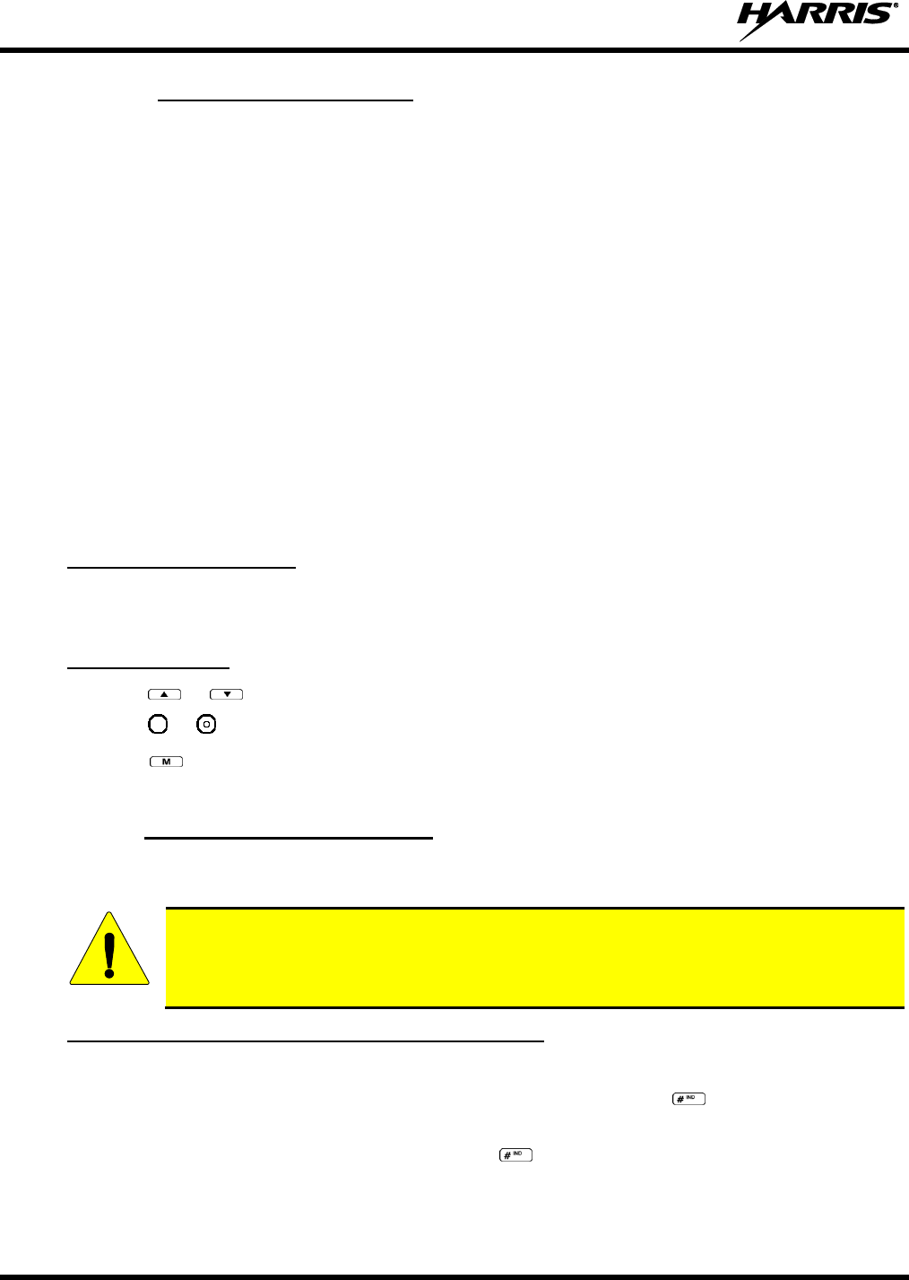
14221-1100-2010, Rev. E
64
8.34.6 Using XCOV-PROF Mode
In XCOV-PROF mode, client attachment to a V-TAC is based on profile rather than talk group.
XCOV-PROF mode allows the transmission and receipt of voice calls on any talk group in the profile as
opposed to only one talk group. XCOV-PROF allows emergencies on a non-selected talk group based on
the emergency behaviors of the profile. XCOV-PROF minimizes data traffic between the client and V-
TAC while allowing flexibility of voice functionality. As a result, data services between the client and V-
TAC are disabled. The radio will automatically connect to a V-TAC if it cannot find a network channel.
Note the following regarding XCOV-PROF mode:
The client profile must match the V-TAC.
The client profile used to connect to the V-TAC must have been previously provisioned to the client
prior to connection. If the profile is not in the client’s personality, the client cannot connect to the V-
TAC.
Neither the V-TAC nor a client can change the profile once it has entered XCOV-PROF mode. The
Profile menu will be disabled.
Client global profiles are disabled.
8.34.6.1 Access XCOV-PROF Mode
System Model Radios Only:
Enter the command *63 # to set the radio to use the XCOV-PROF mode.
Press *60 # to disconnect from the XCOV-PROF mode.
Both Model Radios:
1. Press or until the Client Mode menu appears.
2. Press or until XCOV-PROF is displayed.
3. Press to confirm mode selection. The radio reverts to the dwell display and the V-TAC icon is
displayed.
8.34.7 Use Scene-of-Incident Mode
The Scene-of-Incident mode (SOI) is user-selectable. The SOI mode provides a local repeater function
(V-TAC) with no network connection.
When operating in the SOI mode, the radio is disconnected from the OpenSky network.
Therefore, communications with radios and dispatch personnel on the network is not
possible.
SOI Mode, Manual Channel Entry (System Model Only)
1. Press *4#.
2. The radio prompts for the channel. Enter the channel number and press to confirm channel.
3. The radio prompts for the band. Table 8-12 lists valid bands and their definitions. Enter the number
assigned for the desired frequency band and press to confirm.
4. The radio reverts to the dwell display. If accepted, you will be switched off the network, and be
communicating locally through the V-TAC.
CAUTION
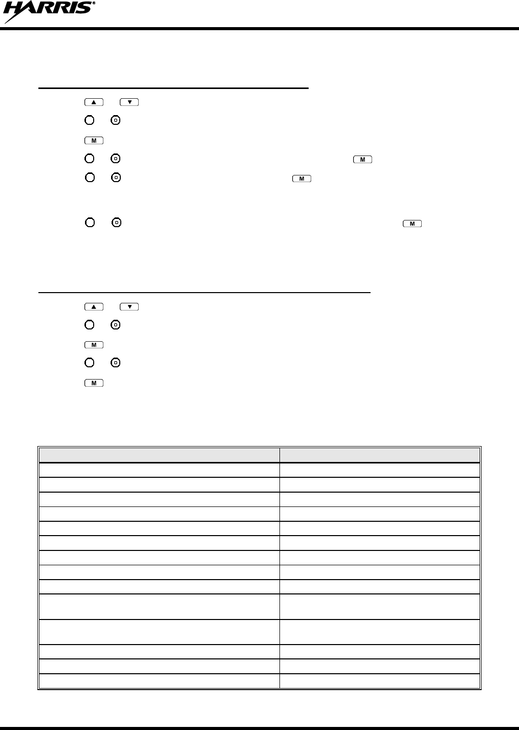
14221-1100-2010, Rev. E
65
Press *40# or use the Client Mode menu to return to normal operation (Network Mode). The personality
and profile in use at the time the radio entered SOI mode is restored.
SOI Mode, Manual Channel Entry (Both Model Radios)
1. Press or until the Client Mode menu appears.
2. Press or until SOI is displayed.
3. Press to confirm mode selection.
4. Press or until “Manual Select Chan” is displayed and press .
5. Press or to edit the right-most digit and press to advance to the next digit. Repeat until the
desired channel is entered.
6. The radio then prompts the user to edit the band. Table 8-12 lists valid bands and their definitions.
Press or to edit the number assigned to the frequency band and press to confirm and enter
the SOI mode.
Use the Client Mode menu to return to normal operation (Network Mode). The personality and profile in
use at the time the radio entered SOI mode is restored.
SOI Mode, Pre-Programmed Channel Selection (Both Model Radios)
1. Press or until the Client Mode menu appears.
2. Press or until SOI is displayed.
3. Press to confirm mode selection.
4. Press or scroll through a list of pre-programmed channels.
5. Press to confirm channel and enter SOI mode.
Use the Client Mode menu to return to normal operation (Network Mode). The personality and profile in
use at the time the radio entered SOI mode is restored.
Table 8-12: Band Definitions
RF BAND
RF CHANNEL NUMBER
0 = SMR
Band 0: 1-830
1 = AMPS
Band 1: 1-600
2 = BORDER
Band 2: 1-600
3 = 700 MHz Band 1
Band 3: 1-477
4 = 700 MHz Band 2
Band 4: 481-957
5 = 700 MHz Band 3
Band 5: 1-477
6 = 700 MHz Band 4
Band 6: 481-957
7 = 900 MHz
Band 7: 1-399
8 = 800 MHz Rebanded
Band 8: 1-830
9 = 400 MHz T band WB
Band 9: 1-6718
(Independent Separation Between TX and RX)
10 = 400 MHz T band NB
Band 10: 1-6718
(Independent Separation Between TX and RX)
11 = 400 MHz T band Temp (NYPD only)
Band 11: 1-120
14 = 700 MHz reband WB
Band 14: 1-957
15 = 700 MHz reband NB
Band 15: 1-959
14221-1100-2010, Rev. E
66
9 EDACS, CONVENTIONAL, AND P25 OPERATION
9.1 TURNING ON THE RADIO
1. Power ON the radio by rotating the POWER ON-OFF/VOLUME knob clockwise. A short alert
signal (if enabled through programming) indicates the radio is ready to use.
The radio can be programmed to require the entry of a PIN in order to operate the radio.
Check with your System Administrator if you forget your PIN. As the PIN is entered, an
asterisk is displayed for each digit. The actual value is not displayed.
2. The display shows the last selected system and group or a default system and group (depending on
programming).
3. Adjust the POWER ON-OFF/VOLUME knob to the desired volume level.
4. Select the desired system and group. The display indicates the current system and group names.
5. The radio is now ready to transmit and receive calls.
In the trunked environment, CC SCAN will be displayed if communication with the
system's control channel cannot be established. This may occur if, for example, the radio
is out of range of the trunking site. It may be necessary to move to another location or
select another trunking system to re-establish the control channel link for trunked mode
operations. CC SCAN is displayed on the group line until a control channel is accessed.
NOTE
NOTE
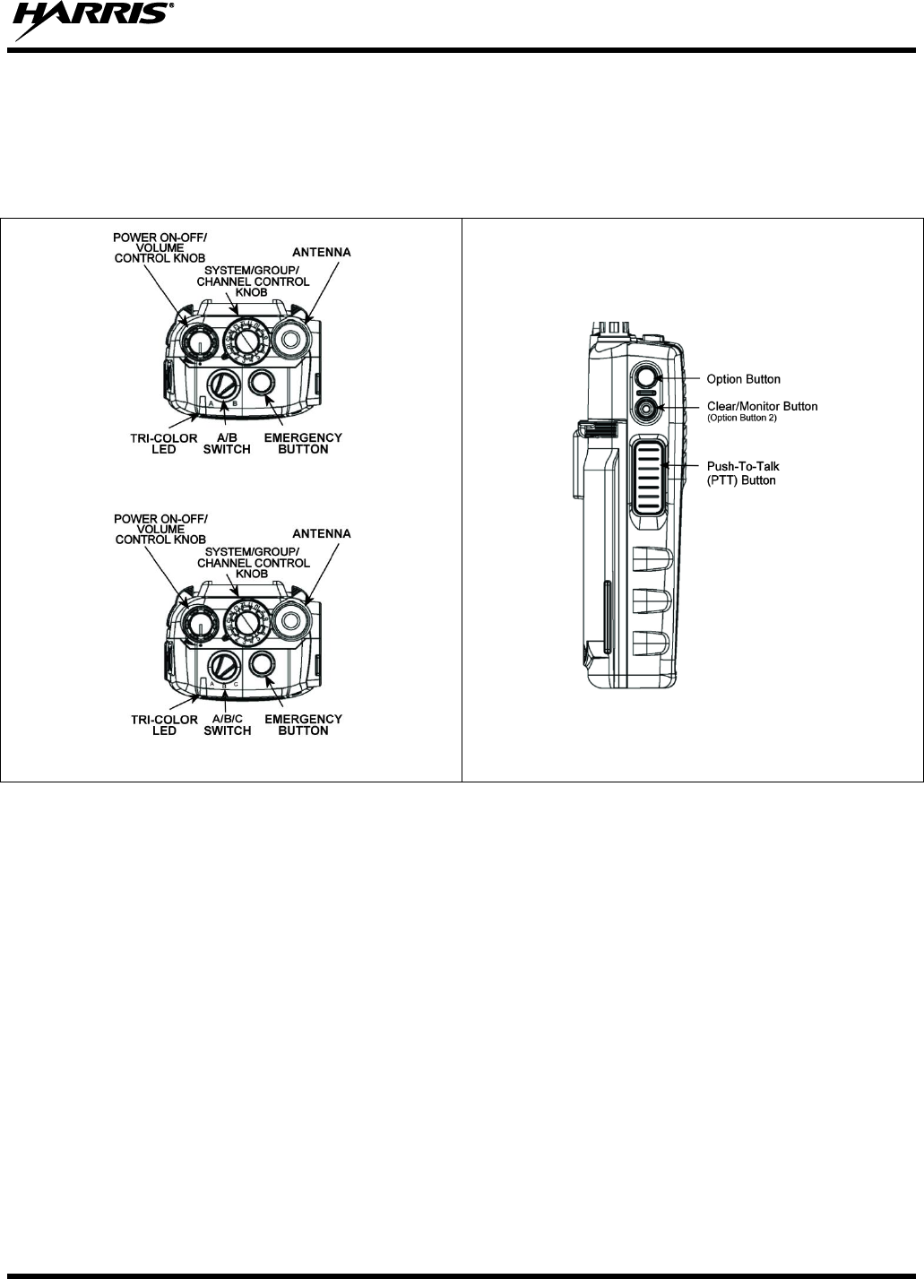
14221-1100-2010, Rev. E
67
9.2 CONTROLS
The XG-75P portable radios feature two rotary control knobs, an emergency button, and a dual-position
A/B switch located on the top of the radio (Figure 9-1). The Push-To-Talk (PTT) button and two option
buttons are located on the side (Figure 9-2) of the radio. The front mounted keypad of the System model
has 15 buttons and the Scan model has six buttons. Refer to Figure 9-3 and Figure 9-4, respectively.
With A/B Switch
With A/B/C Switch
Figure 9-1: Top View
Figure 9-2: Side View
14221-1100-2010, Rev. E
68
9.2.1 Buttons, Knobs, and Switch
The functions of the buttons and knob controls vary depending on mode of operation. The dual position
A/B switch is currently software defined only in ECP mode. Primary functions of the button, switch, and
knob controls are discussed in general terms in Table 9-1.
Table 9-1: Buttons, Knobs, and Switch Functions
POWER ON/OFF-VOLUME
CONTROL KNOB
Applies power to the radio and adjusts audio volume.
The radio can be programmed to require the entry of a PIN in order
to operate the radio. Check with your System Administrator if you
forget your PIN. As the PIN is entered, an asterisk is displayed for
each digit. The actual value is not displayed.
Rotating the control clockwise applies power to the radio. If enabled through
programming, a single alert tone indicates the radio is operational.
Rotating the control clockwise increases the volume level. A minimum volume
level can be programmed into the radio to prevent missed calls due to a low
volume setting. While adjusting the volume, the display momentarily indicates the
volume level (i.e., VOL=31). The volume ranges from a minimum programmable
level of zero (displayed as OFF in the display) up to 40, which is the loudest level.
SYSTEM/GROUP/CHANNEL
CONTROL KNOB
Used to select groups/channels. This is a 16-position rotary knob.
EMERGENCY/HOME BUTTON
Automatically selects a pre-programmed “Home” Group/System by pressing and
holding for a programmed duration OR it can be used to declare an emergency by
pressing and holding for a programmed duration. The button can be pre-
programmed for either operation, but not both.
PUSH-TO-TALK (PTT)
BUTTON
The PTT button is pressed before voice transmission begins.
Activates one of a number of programmable software options selected during PC
programming.
Exits the current operation (removing all displays associated with it) and returns
the radio to the selected talk group.
A/B SWITCH
OR
A/B/C SWITCH
The function of the A/B or A/B/C switch is user-defined from a list of
programmable options.
NOTE
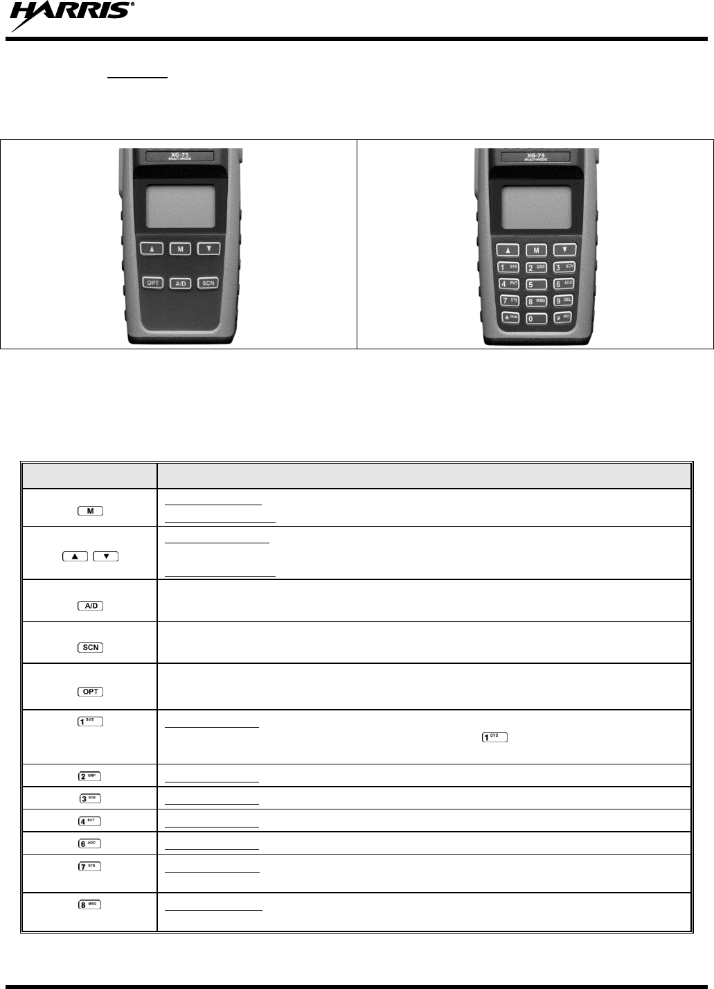
14221-1100-2010, Rev. E
69
9.2.2 Keypad
The front mounted keypad of the Scan model has six buttons and System model has 15 buttons. Refer to
Figure 9-3 and Figure 9-4, respectively.
Figure 9-3: Scan Model Front Panel
Figure 9-4: System Model Front Panel
The primary and secondary functions of each key, where applicable, are described in Table 9-2 and the
following section.
Table 9-2: XG-75P Front Keypad Functions
KEY
FUNCTION
Primary Function: Accesses the menu.
Secondary Function: Activates a selected item within the menu, similar to an “Enter” key.
Primary Function: Scrolls through available systems, groups, or channels, depending on
personality programming.
Secondary Function: Changes the selection for an item within a list.
Adds/deletes selected groups or channels from the scan list of the currently selected system.
Toggles scan operation on and off.
Activates one of any programmable software options selected during radio programming, i.e.,
high/low TX power and talkaround.
Primary function: Selects a specific system. If the rotary knob is used to select the system and
more than 16 systems are programmed in the radio, the key is used to select additional
banks (groupings) of systems.
Primary function: Selects a specific group.
Primary function: Turns the Scan operation on and off.
Primary function: Enables or disables encryption for the system/group/channel displayed.
Primary function: Adds groups or channels from the currently selected system to the scan list.
Primary function: The Status key accesses the status list (0-9) permitting the transmission of
a pre-programmed status message to an EDACS or P25 site.
Primary function: The Message key accesses the message list (0-9). The Message key
permits the transmission of a pre-programmed message to an EDACS or P25 site.
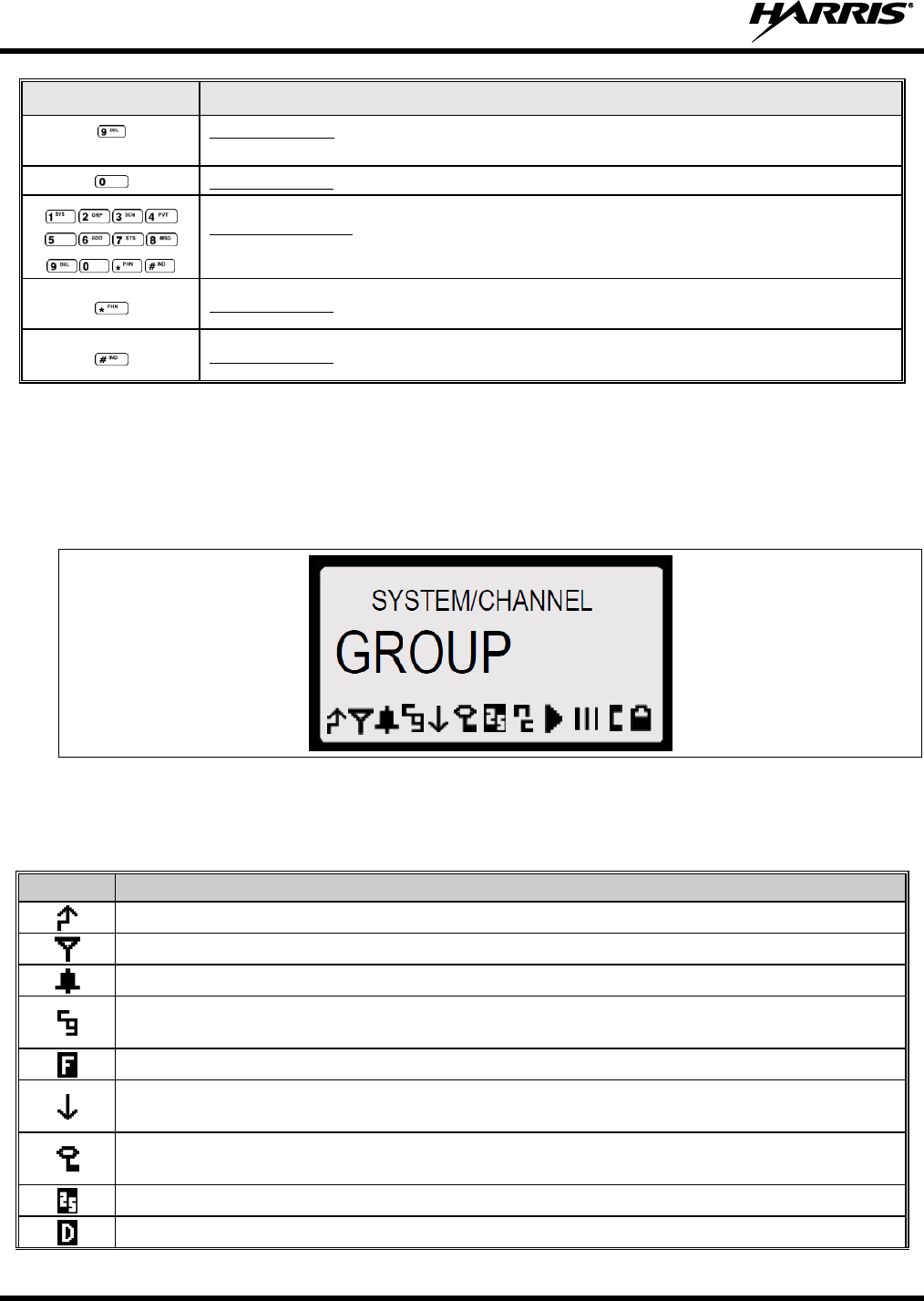
14221-1100-2010, Rev. E
70
KEY
FUNCTION
Primary function: Deletes selected groups or channels of the currently selected system from
the Scan list.
Primary function: Inverts display – Toggle normal/invert. Requires ECP R16B or later.
Secondary function: The secondary function of these keys acts as a typical DTMF telephone
pad, and are used to place telephone interconnect and individual (unit-to-unit) calls.
Primary function: In EDACS and P25 modes, initiates telephone interconnect calls.
Primary function: In EDACS and P25 modes, initiates individual, unit-to-unit calls.
9.3 DISPLAY
The XG-75P display is made up of four lines containing twelve alpha-numeric character blocks each. If
programmed, the display backlighting will illuminate upon power up or when radio controls are operated.
Specific display characteristics will be discussed in following sub-sections.
Figure 9-5: XG-75P Radio Display
Table 9-3 describes the icons that may be displayed by the XG-75P during operation.
Table 9-3: Status Icons Descriptions
ICON
DESCRIPTIONS
Steady – during all radio transmissions.
Steady – “Busy” transmitting or receiving, call queued.
Steady – T99 Mode enabled.
Steady – Channel Guard enabled.
If icon is not visible – Channel Guard is disabled.
Steady – EDACS system in Failsoft™ mode.
Steady – transmit at low power.
If icon is not visible – transmit at high power.
Steady – transmit in encrypt mode.
Flashing – receiving an encrypted call.
Steady – Indicates the current channel is set up as a Project 25 (P25) channel.
Steady – Indicates the current channel is set up as a ProVoice channel.
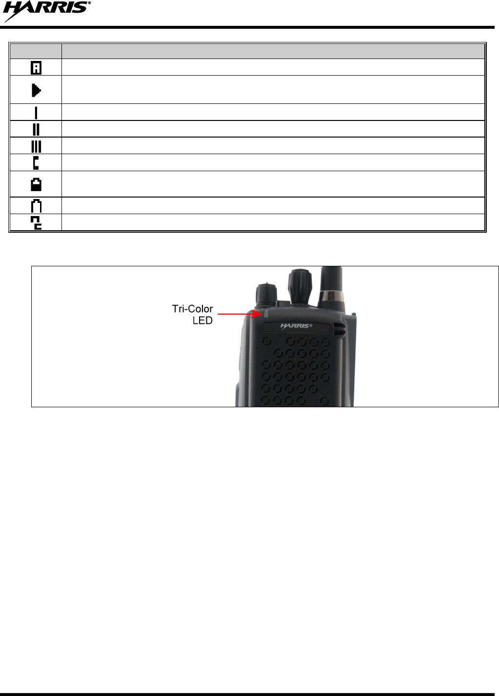
14221-1100-2010, Rev. E
71
ICON
DESCRIPTIONS
Steady – Indicates the current channel is set up as an analog channel.
Animated (rotates clockwise) – scan mode enabled.
If icon is not visible – scan is disabled.
Steady – priority 1 group or channel.
Steady – priority 2 group or channel.
Steady – group or channel in scan list.
Steady – special call mode (individual or telephone).
Steady – battery charge indicator. The battery charge indicators illustrate approximate level
only, based on battery voltage.
Flashing – Low battery indicator.
Steady – Noise cancelling is enabled.
9.4 TRI-COLOR LED
Figure 9-6: Tri-Color LED
The Tri-Color LED changes color to indicate radio status and is visible from both the front and top of the
radio (see Figure 9-1). In addition, the mode of operation may also help determine what the color of the
LED represents.
Green: Receiving
Red: Transmitting Unencrypted
Orange: Transmitting Encrypted
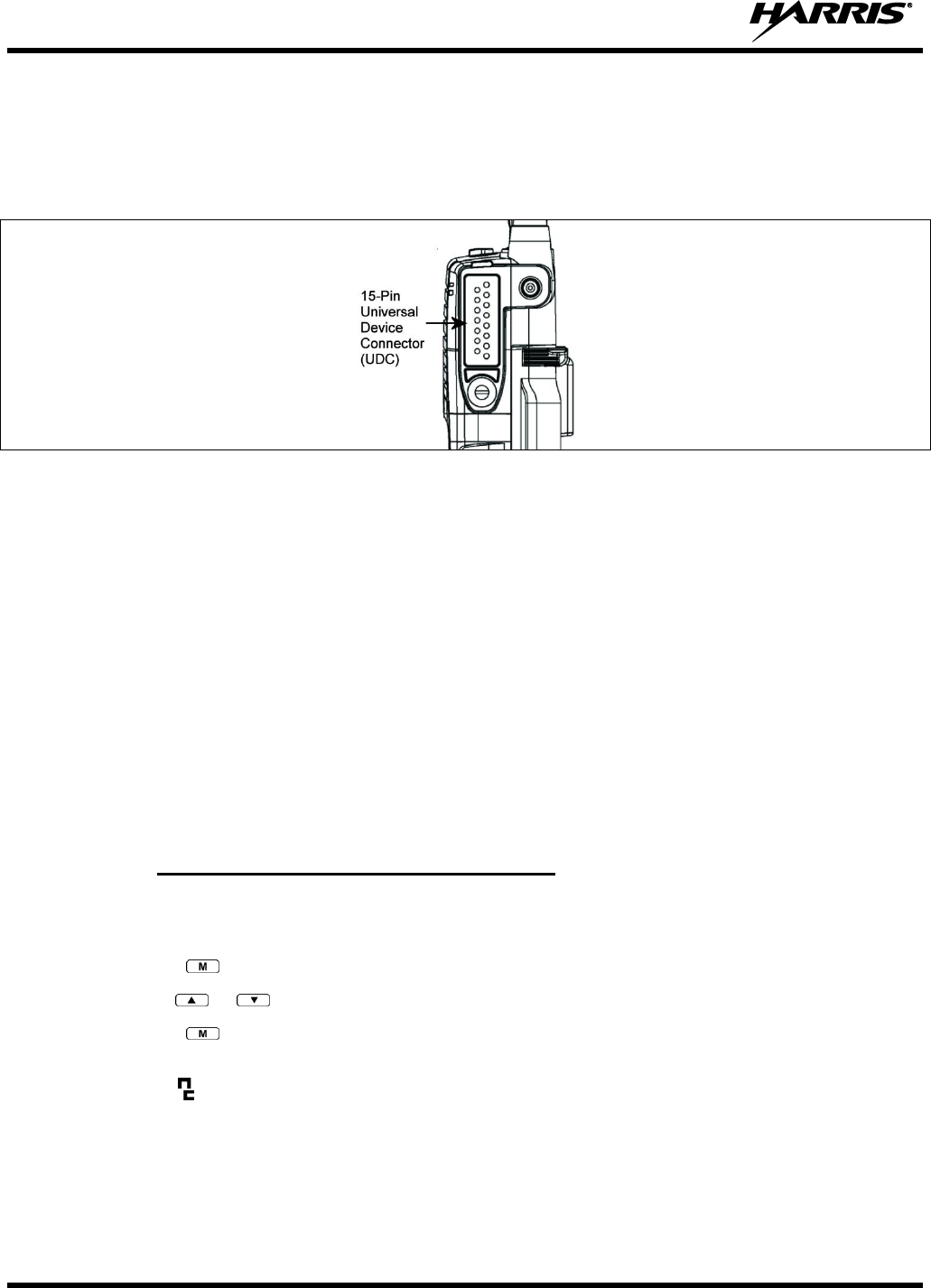
14221-1100-2010, Rev. E
72
9.5 UNIVERSAL DEVICE CONNECTOR
The Universal Device Connector (UDC) provides connections for external accessories such as a headset,
a speaker-microphone, audio test box, audio test cables, and programming cables. The UDC is located on
the right side of the radio, opposite the PTT Button. The UDC facilitates programming and testing the
radio. The UDC pins perform different functions depending on the accessory attached to the UDC.
Figure 9-7: XG-75P 15-Pin Universal Device Connector
9.6 NOISE CANCELLATION
The XG-75P features Harris’ proprietary noise suppression capability to provide clear and crisp voice
quality in high-noise environments for use in any mode, including both analog and digital
communications.
The XG-75P has two microphones; one located on the front (primary) and one on the rear (secondary).
The primary microphone operates in exactly the same manner as a normal radio and is the one you talk
into. The secondary microphone is used to pick up the surrounding noise when noise cancellation is
turned on.
In the case where noise cancellation is enabled and a speaker microphone is attached to the XG-75P, talk
into the speaker microphone. In this mode, XG-75P front microphone is used to pick up the surrounding
noise, and the rear microphone is unused.
If the secondary microphone is blocked, the XG-75P operates as though noise cancellation is turned off.
9.6.1 Turning Noise Cancellation On and Off
A button on the radio or the A/B switch can be programmed to toggle noise cancellation on or off.
OR
1. Press the button.
2. Use the or button to select “NOIS CAN.”
3. Press the again to toggle noise cancellation on or off.
The top line of the display will briefly display “NC ON” or “NC OFF.” When noise cancellation is
enabled, the icon is displayed on the bottom of the display.
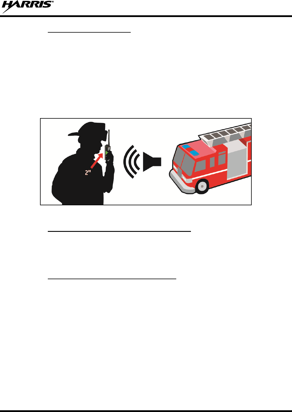
14221-1100-2010, Rev. E
73
9.6.2 Using Noise Cancellation
When using the noise cancellation feature, observe the following:
Talk within two (2) inches of primary microphone (see Figure 9-8).
Speak clearly, loudly, and with authority.
If possible, face the noise source when talking into the radio (see Figure 9-8).
Ensure the primary and secondary microphones are not covered. See Section 9.6.4 for more
information on the primary and secondary microphones.
In very noisy environments, it is okay to yell into the radio. The radio can handle very loud input
levels.
Figure 9-8: Using the Noise Cancellation Feature
9.6.3 The Effect of Distance from the Microphone
Unlike a normal microphone system, noise cancellation makes the level of your voice diminish quickly as
you move away from the radio. In essence, the radio starts to see your voice as surrounding noise.
Whereas, you may be comfortable speaking up to a foot away from the front of a normal radio, noise
cancellation requires that you keep it close.
9.6.4 Primary versus Secondary Microphone
9.6.4.1 Without a Speaker Microphone Attached
The primary microphone is located on the front of the radio and the secondary is on the back of the radio.
9.6.4.2 With a Speaker Microphone Attached
When a speaker microphone is attached, the radio electronically switches over to use the radio’s front
microphone as secondary. The microphone on the attached speaker microphone becomes the primary
microphone.

14221-1100-2010, Rev. E
74
9.7 STATUS MESSAGES (EDACS AND P25 TRUNKED)
During radio operation, various radio Status Messages may be displayed. The messages are described
below.
MESSAGE
NAME
DESCRIPTION
QUEUED
Call Queued
Indicates the system has placed the call in a request queue.
SYS BUSY
System Busy
Indicates the system is busy, no channels are currently available, the queue
is full, or an individual call is being attempted to a radio that is currently
transmitting.
DENIED
Call Denied
Indicates the radio or talkgroup is not authorized to operate on the selected
system or talkgroup.
CC SCAN
Control
Channel Scan
Indicates the control channel is lost and the radio has entered the Control
Channel Scan mode to search for the control channel. This is usually an out
of range indication.
WA SCAN
Wide Area
Scan
Indicates the radio has entered the Wide Area Scan mode to search for a
new system. Wide Area Scan mode must enabled through programming.
SYSC ON
System Scan
Features On
Indicates the System Scan features are enabled.
SYSC OFF
System Scan
Features Off
Indicates the System Scan features are disabled.
LOW BATT
Low Battery
Battery voltage has dropped to the point to where the radio is no longer
able to transmit. The radio will still receive calls until the battery is
discharged beyond the point of operation, at which time the radio
automatically shuts down.
RXEMER
Receive
Emergency
Indicates an emergency call is being received. This message flashes on
line two.
TXEMER
Transmit
Emergency
Indicates an emergency call has been transmitted on this radio. This
message will be flashing on line two.
VOL=31
Volume Level
Indicates the current volume level. The volume level display ranges from
OFF (muted) to 40 (loudest).
WHC
Who Has
Called
Indicates an individual call has been received, but not responded to. The
indicator turns off if the individual call mode is entered, the system is
changed, or the radio is turned off and then on again.
UNKNOWN
Unknown ID
Indicates an individual call is being received from an unknown ID.
9.8 ERROR MESSAGES
If either of the Error Messages shown below is displayed, the radio is programmed incorrectly or needs
servicing.
DSP ERR
ERR=XXXX
(Power Up only)
or
DIG V x
ERR x
Where xxxx is the error code and DSP ERR or DIG V ERR is the message.
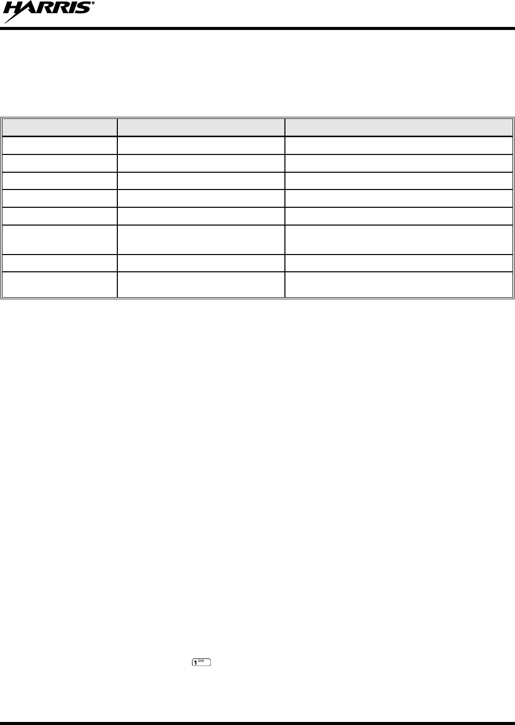
14221-1100-2010, Rev. E
75
9.9 ALERT TONES
The XG-75P radio provides audible Alert Tones or “beeps” to indicate the various operating conditions
(see Table 9-4).
Table 9-4: Alert Tones
NAME
TONE
DESCRIPTION
Call Originate
one short mid-pitched
OK to talk after pressing the push-to-talk button.
Call Queued
one high-pitched
Call queued for processing.
Autokey
one mid-pitched
Queued call received channel assignment.
System Busy
three low-pitched
System busy or unable to complete call.
Call Denied
one low-pitched
Radio is not authorized on the system or group.
Carrier Control Timer
five high-pitched/one long low-pitched
PTT depressed for maximum length of time.
Low Battery
one low-pitched/one short mid-pitched
Low battery.
TX Low Battery Alert
one low-pitched
After PTT - battery too low to transmit.
9.10 VOICE ANNUNCIATION
When enabled via programming, the Voice Annunciation feature provides audible feedback for various
radio operations. The radio can be programmed to play an audio message for any or all of the following.
This message can be a pre-recorded (canned) message or a user-recorded message.
Zone changes
Channel changes
System changes
Encryption On/Off
Monitor On/Off
Noise Cancellation On/Off
Scan On/Off
Talkaround On/Off
Tx Disabled On/Off
For more information on configuring the radio for Voice Annunciation, refer to the Voice Annunciation
Feature manual, 14221-7200-6110.
9.11 SYSTEM SELECTION
METHOD 1:
From the control knob: If system selection is programmed to the
System/Group/Channel control knob, select a system by turning the knob to the
desired system number position (1-16). The display registers the new system name on
line one. The button can be programmed to provide access to a “2nd bank” of 16
system number positions (17-32).
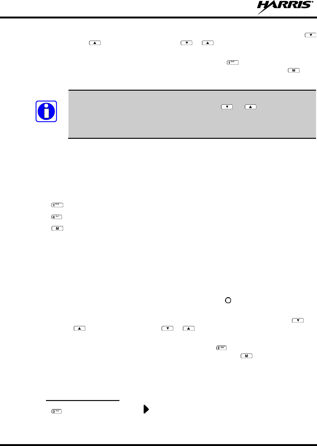
14221-1100-2010, Rev. E
76
METHOD 2:
From the keypad: If system selection is programmed as the primary function of
and , select a system by pressing or to scroll through the system list. The
display registers the new system name on line one.
METHOD 3:
(System model radios only) Direct Access: Press to enter the system select
mode. Press the numeric key, which is mapped to the desired system. Press . The
radio will move to the selected system.
If system selection is programmed to the System/Group/Channel control knob, direct
access to systems will not be available. Pressing or will scroll through
different sets of 16 systems each (banks) if more than 16 systems are programmed into
the radio. The systems within each bank are then selectable via the
System/Group/Channel control knob as described previously in METHOD 1.
Example:
System: 1 = North
2 = South
3 = East
4 = West
1. Press . (South is the currently selected system.)
2. Press . (Press 4 to select “West” system.)
3. Press . (West is the newly selected system.)
9.12 GROUP/CHANNEL SELECTION
Several methods can be used to select a new group or channel.
METHOD 1:
From the Control knob: If group selection is programmed to the System/Group/Channel
control knob, select a group by turning the System/Group/Channel control knob to the
desired group number position. The display registers the new group name on line two.
If the knob is moved to a position greater than the number of programmed groups, the
highest programmed group will remain selected. The button can be programmed to
provide access to a “2nd bank” of 16 group number positions (17-32).
METHOD 2:
From keypad: If group selection is programmed as the primary function of and
select a group by pressing or to scroll through the group list. The display
registers the new group name on line two.
METHOD 3:
(System model radios only) Direct Access: Press to enter the group select mode.
Press the numeric key mapped to the desired group. Press . The radio will move
to the selected group.
9.13 MODIFY SCAN LIST
9.13.1 System Model Radio
1. Press to toggle scan off and verify is not displayed.
2. Select group or channel.
NOTE
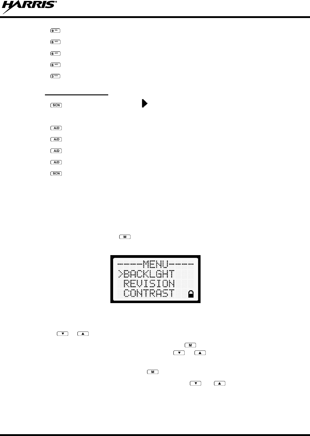
14221-1100-2010, Rev. E
77
3. Press once to remove group or channel from list.
4. Press once to add as a normal group or channel.
5. Press twice to add as a Priority 2 group.
6. Press three times to add as a Priority 1 group.
7. Press to re-start scanning.
9.13.2 Scan Model Radio
1. Press to toggle scan off and verify is not displayed.
2. Select group or channel.
3. Press once to remove group or channel from the list.
4. Press once to add as a normal group or channel.
5. Press twice to add as a Priority 2 group.
6. Press three times to add as a Priority 1 group.
7. Press to re-start scanning.
9.14 MENU
The Menu function accesses features that are not available directly from the keypad. The menu items
available and the order of menu items is configurable through programming. Upon radio power up, the
menu item that is at the top of the menu list will always be displayed first. Subsequent access to the menu
function will return the last menu item that was shown in the display and cursor position.
1. To enter the menu mode, press .
2. Upon entering the menu selection mode, menu options will appear in the display (see Figure 9-9).
Figure 9-9: Menu Display
3. The radio will continue to receive and transmit normally while in the menu.
4. Use the or keys to scroll through the menu options.
5. Align the > with the desired menu option and press to select it. The menu item's parameter
setting shown in the display can be changed using or to scroll through the list of parameter
values.
6. Once the desired setting is reached, press to store the value and return to the main display.
For menu items that display radio information, pressing or will scroll through a list of
informational displays. Possible menu items are listed in Table 9-5.
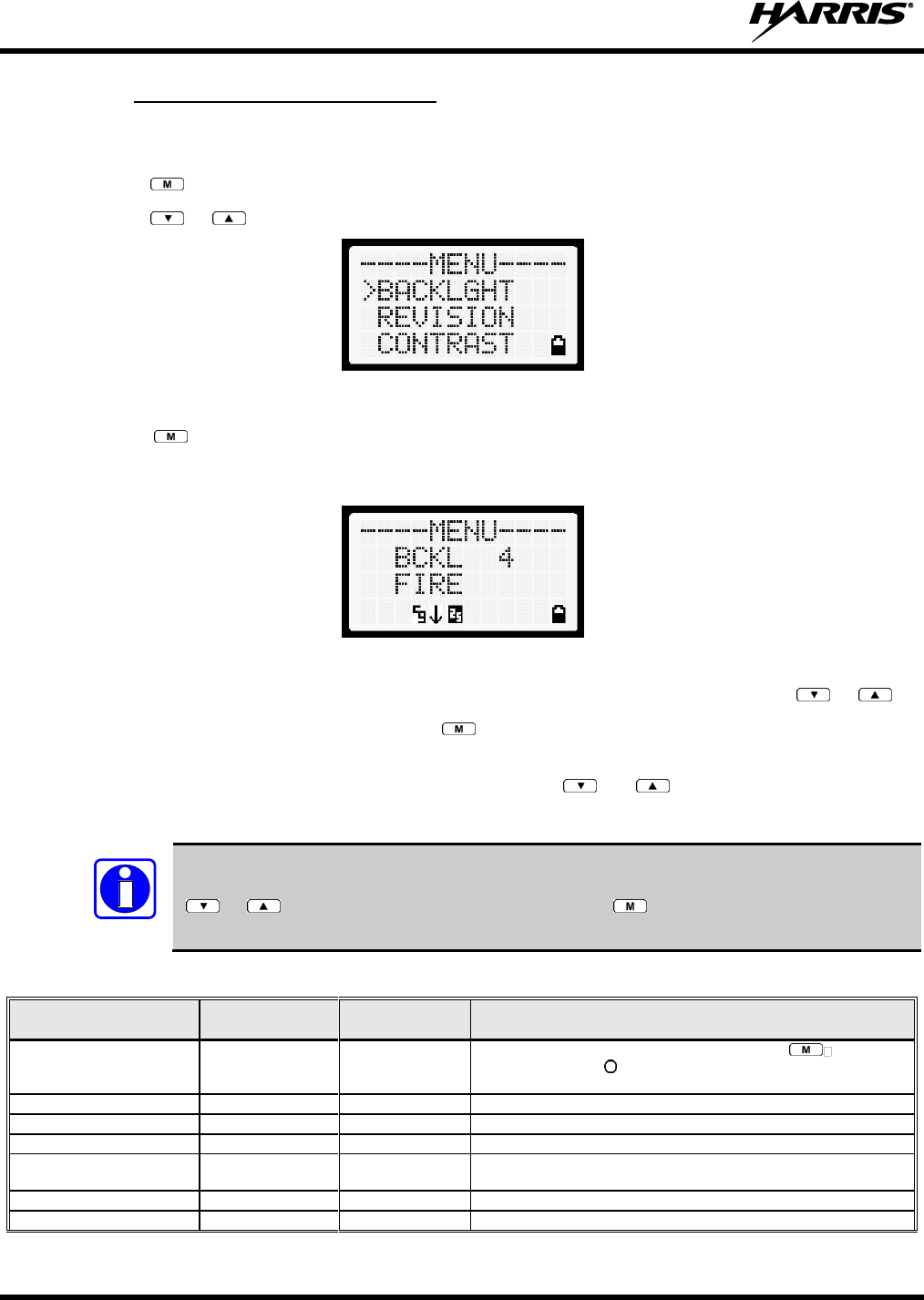
14221-1100-2010, Rev. E
78
9.14.1 Menu Item Selection Process
An example of the backlight menu item selection process and menu item parameter change is shown in
Figure 9-10.
1. Press . The menu mode is entered.
2. Press or until the display shows:
Figure 9-10: Backlight Menu Item Selection Parameter
3. Press . The backlight menu item is activated. Line one shows the active menu item and its
current parameter setting. Line two shows the currently selected system or group name (see Figure
9-11).
Figure 9-11: Backlight Menu Display
4. The menu item's parameter setting shown in the display can now be changed by using or .
5. Once the desired setting is reached, press to store the value and return the menu option selection
level.
For menu items that display radio information pressing or will scroll through a list of
informational displays. An example of information displays is shown in Table 9-5.
The TX POWER menu item, when selected, toggles LOW/HIGH power. It does not use
or to scroll nor is an additional press of the button required.
Table 9-5: Menu Item Information
FEATURE
DISPLAY
PARAMETER
SETTING
COMMENT
Keypad Lock
KEY LOCK
Locked
Unlocked
Locks the keypad. To unlock; press and release then within
1 second press the button. This sequence is also a short cut to
locking the keypad.
Backlight Adjust
BACKLGHT
OFF, 1 thru 6
Selects the light level for backlighting.
Contrast Adjust
CONTRAST
1, 2, 3, 4
Selects the display contrast level.
Transmit Power Select
TX POWER
HIGH or LOW
Selects radio output power mode.
Radio Revision Information
REVISION
N/A
Selects the information display to view. Informational display only
(see Table 9-6). No user selectable settings.
Toggle Scan On/Off
SCAN
ON/OFF
Toggles Scan operation ON/OFF.
Toggle Private Mode
PRIVATE
ON/OFF
Toggles Private Mode ON/OFF.
NOTE
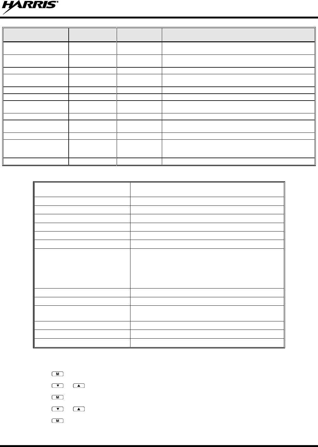
14221-1100-2010, Rev. E
79
FEATURE
DISPLAY
PARAMETER
SETTING
COMMENT
Display Current Encryption
Key
DISP KEY
N/A
Displays current encryption key. Informational display only. No
selectable settings.
Display Current Home
Group/Channel
HOME
N/A
Selects Home Group/Channel.
Select Desired System
SYS SEL
N/A
Selects a new system.
Add Group/Channel to Scan
List
SCAN ADD
N/A
Adds to Scan List.
Delete Group/Channel
SCAN DEL
N/A
Deletes Group or Channel from Scan List.
Add/Delete Scan List
SCAN A/D
N/A
Add or Delete from Scan List.
Select Telephone Numbers
From Phone List
PHN CALL
N/A
Trunked Only.
Data Operation
NO DATA
ON/OFF
Trunked Only. Toggles Data Operation ON/OFF.
Select Individual Call from
IC List
IND CALL
N/A
Select Group
GRP SEL
N/A
Feature Encryption Display
FEATURES
N/A
Indicates current features programmed into the radio as well as
certain information required to add features to the radio.
Informational display only. No user selectable settings.
System Scan Enable
SYS SCAN
ON/OFF
Toggles System Scan feature ON/OFF.
Table 9-6: Information Display
RADIO ID
XXXXXXXX
LID in EDACS IP. In CONV it has no meaning.
RAM SIZ
RAM Size
FLSH SIZ
Flash Size
RF BAND
Frequency Band
PERS VER
Software Version
DSP DATE
Date DSP code was built.
DSP TIME
Time DSP code was built.
DSP FEAT
The DSP Features supported by the DSP code, in Hexadecimal.
Bit mapped (see IPC spec for details):
0x0001 – Conventional
0x0002 – EDACS
0x0010 – AMPF
0x0020 – undefined
DSP VER
DSP Software Version
FLSH VER
FLASH Software
HARRIS
(C) 2011
Copyright
PERSNLTY
Personality Name
BLD DATE
Date host (ARM) code was built.
BLD TIME
Time host (ARM) code was built.
9.15 BACKLIGHT ADJUST
1. Press to access the menu.
2. Press or to scroll through menu until “BACKLGHT” appears.
3. Press to select the backlight menu.
4. Press or to scroll through available settings off, 1 through 6.
5. Press to select new backlight setting.
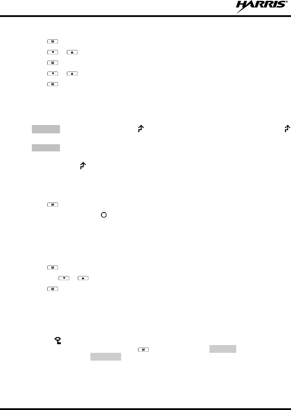
14221-1100-2010, Rev. E
80
9.16 CONTRAST ADJUST
1. Press to access the menu.
2. Press or to scroll through menu until “CONTRAST” appears.
3. Press to select Contrast menu.
4. Press or to adjust contrast setting from 1 - 4.
5. Press to select new contrast setting.
9.17 DECLARE AN EMERGENCY
1. Press and hold the red Emergency/Home button. The length of time to hold the button is
programmable; check with the system administrator.
2. *TXEMER* will flash in the display, and will be displayed. After 2-3 seconds the transmit icon
will turn off.
3. *TXEMER* continues to flash until the emergency is cleared. See Section 9.23 for additional
emergency operation.
4. Press the PTT and will reappear.
5. Release PTT when the transmission is complete.
9.18 LOCKING/UNLOCKING KEYPAD
1. Press button.
2. Within 1 second, press the button on the side of the radio.
9.19 HIGH/LOW POWER ADJUSTMENT
Transmit power adjustment is possible if enabled through programming. Within conventional systems,
transmit power is adjustable on a per channel basis. Within EDACS trunking systems, transmit power is
adjustable on a per system basis.
1. Press .
2. Using the or keys, select “TX POWER.”.
3. Press again to toggle between High and Low power.
4. “POWER = HIGH” or “POWER = LOW” will appear momentarily on the top line of the display.
9.20 ENCRYPTION
The XG-75P portable radio supports AES and DES encryption. When operating on a group or channel
programmed for encryption, all transmissions are encrypted, and the radio receives clear and encrypted
signals. The icon is displayed when encryption is enabled. If enabled via programming, the encryption
can be enabled or disabled by pressing the key and selecting the PRIVATE menu option. If not
enabled, the radio displays FRCD PVT when you try to disable encryption.
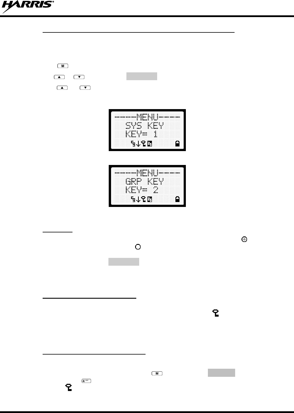
14221-1100-2010, Rev. E
81
9.20.1 Displaying the Currently Used Cryptographic Key Number
To display the Currently Used Cryptographic Key Number for either the system encryption key (for
special call such as individual, phone, all, agency or fleet) or the group/channel key (for group or
conventional calls), perform the following procedure:
1. Press the button.
2. Use the or button to select DISP KEY.
3. Use the or button to toggle between displaying the system key (Figure 9-12) or the
group/channel key (Figure 9-13).
Figure 9-12: System Encryption Key Display
Figure 9-13: Group/Channel Encryption Key Display
9.20.2 Key Zero
All cryptographic keys can be zeroed (erased from radio memory) by pressing the button and while
still pressing this button, press and hold the button. Press both buttons for 2 seconds. A series of beeps
will begin at the start of the 2 second period and then switch to a solid tone after the keys have been
zeroed. The display will indicate KEY ZERO.
If the cryptographic key(s) are zeroed, one or more keys must be transferred from the Keyloader into the
radio before private communications may continue.
9.20.3 Receiving an Encrypted Call
When receiving, the radio automatically switches between clear or private operation. If the transmission
being received is an encrypted transmission, it will be decrypted, the icon will be displayed, the
receiver will unsquelch, and the message will be heard in the speaker. For this to occur, the selected
group or channel must be programmed for private operation and the correct cryptographic key must be
loaded into the radio.
9.20.4 Transmitting an Encrypted Call
1. Select the desired group or channel.
2. Place the radio in Private Mode by pressing key, then select PRIVATE from the menu. On a
System radio, the key can be used to toggle the Private Mode on/off. When Private Mode is
enabled, the icon is displayed.
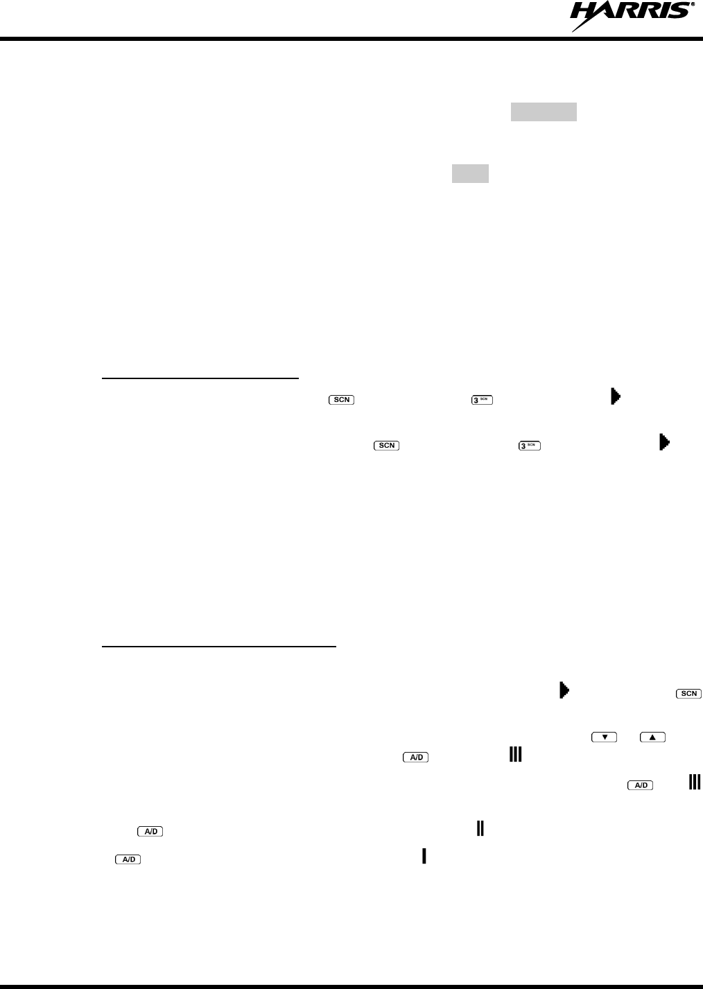
14221-1100-2010, Rev. E
82
3. If the last state of the radio was Private Mode, the Private Mode will be enabled on power up. Also,
the Private Mode will be enabled if forced operation has been programmed in the radio.
If a group or channel is not programmed for Private Mode operation, PVT DIS will be displayed if
an attempt is made to enable private transmit mode. It is not possible to operate on this group/channel
in Private Mode.
If the radio does not have the correct encryption key loaded, NOKY will be displayed and the call will
not be transmitted.
4. Continue with standard transmission procedures. A Private Mode access tone will be heard when the
PTT button is pressed.
9.21 SCANNING TRUNKED GROUPS
Groups that have been previously added to the scan list on a per system basis may be scanned. Each
system's group scan list is retained in memory when the radio is powered off or when the battery pack is
removed.
9.21.1 Turning Scan On and Off
1. Toggle Scan operation on by pressing (Scan model) or (System model). icon rotates
clockwise to indicate radio is scanning.
2. Toggle Scan operation off by again pressing (Scan model) or (System model). will
disappear.
If the radio scans to a group other than the selected group then receives a call on the selected
group, the radio will switch to the selected group. However, if the “scanned-to” group is
programmed at a higher priority the radio will remain on the “scanned-to” group.
The radio will continue scanning if a new group is selected when scan is on.
3. Pressing the PTT button when scan is on will cause the radio to transmit on the displayed group or to
the currently selected group (depending on programming).
9.21.2 Adding Groups to a Scan List
Scan Model Radio
1. Scan must be off to add/delete groups to/from the scan list. If the Scan icon is on, press the
key to turn Scan off.
2. Select the desired group using the System/Group/Channel control knob and/or the or keys.
If the selected group is currently on the list, pressing will display on line three.
3. If the scan list status icon is blank, the group can be added to the scan list by pressing the key.
will be displayed on line three.
4. Press the key a second time to set the group to Priority 2. A is displayed on line three.
5. Press a third time to set the group to Priority 1. A is displayed on line three. The priority level
section sequence only advances the group to the next high priority level and stops at priority level 1.
To select a lower priority level, the group must be deleted from the scan list and then added back to
the scan list. Each new group added to the scan list starts at the lowest priority. If the Priority 1 and
Priority 2 groups are already set and a new group is assigned as Priority 1 or Priority 2, the previously
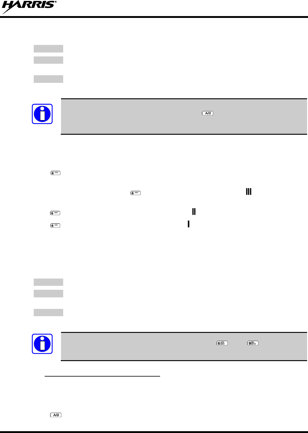
14221-1100-2010, Rev. E
83
assigned group will change to non-priority scanning. One of the following messages may be
momentarily displayed.
SCAN DIS
The radio is not programmed to scan.
FIXED P1
A Priority 1 group has been pre-programmed into the radio. A new Priority 1 group
cannot be selected.
FIXD LST
A fixed scan list has been pre-programmed into the radio. It is not possible to change
the list without reprogramming the radio.
To quickly view multiple group scan status, press then rotate the group knob. Each
group status will appear on the display.
System Model Radio
1. With scan operation turned off, select the desired group to add to the selected trunked system group
scan list.
2. Press . The current priority status of the group will be displayed in column 10 of line three for a
time-out period. If the group is not part of the scan list, the status will be blank.
3. While the status is displayed, press to add the group to the scan list. The icon is displayed on
line three.
4. Press a second time to set the group to Priority 2. The icon is displayed on line three.
5. Press a third time to set the group to Priority 1. The icon is displayed on line three. The priority
level selection sequence only advances the group to next higher priority level and stops at priority
level 1. To select a lower priority level, the group must be deleted from the scan list and then added
back to the scan list. Each new group added to the scan list starts at the lowest priority. If the Priority
1 and Priority 2 groups are already set and a new group is assigned as Priority 1 or Priority 2, the
previously assigned group will change to non-priority scanning. One of the following messages may
be momentarily displayed.
SCAN DIS
The radio is not programmed to scan.
FIXED P1
A Priority 1 group has been pre-programmed into the radio. A new Priority 1 group
cannot be selected.
FIXD LST
A fixed scan list has been pre-programmed into the radio. It is not possible to change
the list without reprogramming the radio.
To quickly view multiple group scan status, press either or the key. Then rotate
the group knob. Each group status will appear on the display.
9.21.3 Deleting Groups from a Scan List
Scan Model Radio
1. With scan operation turned off, select the desired group to delete from the selected trunked system
group scan list.
2. Press . The current status of the group is displayed for a time-out period.
NOTE
NOTE
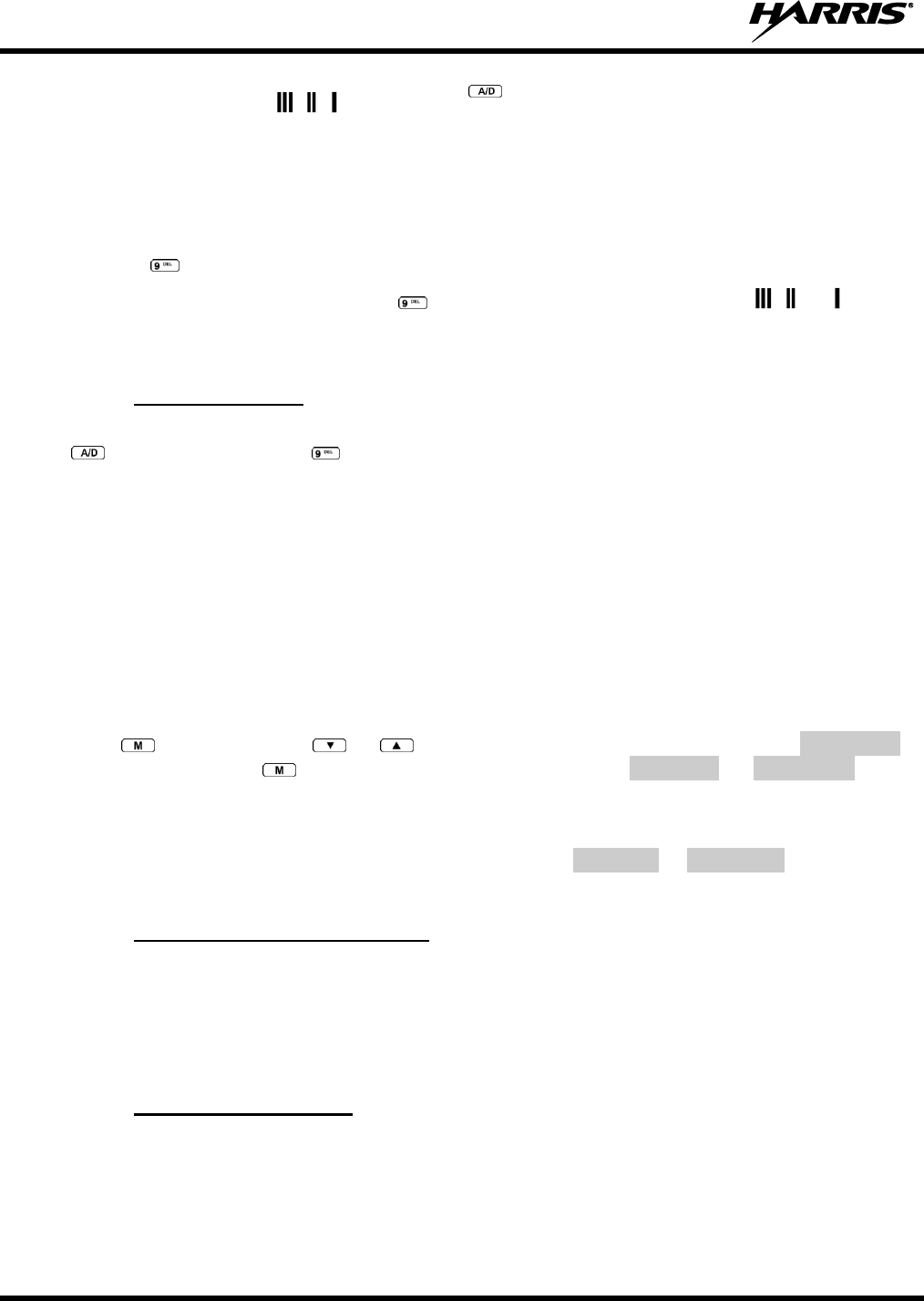
14221-1100-2010, Rev. E
84
3. While the current status is displayed, press until the group from the scan list is "blank." The
sequence is "blank," , , , "blank." Any group that is not in a trunked system group scan list will
show a "blank" for the time-out period when it is the selected channel.
System Model Radio
1. With scan operation turned off, select the desired group to delete from the selected trunked system's
group scan list.
2. Press . The current status of the group is displayed for a time-out period.
3. While the status is displayed, press to delete the group from the scan list. , , or turns off.
Any group that is not in a trunked system group scan list will show a "blank" for the time out period
when it is the selected channel.
9.21.4 Nuisance Delete
A group can also be deleted from the scan list, if it is not the currently selected group, by pressing the
key (Scan model) or the key (System model) during scan operation while the radio is displaying
the unwanted group. The group will be deleted from the system's group scan list in the same manner as if
done using the steps above. Deletions done in this manner will not remain deleted if the radio is powered
off and then powered on.
9.22 SCANNING TRUNKED SYSTEMS
The radio can be programmed using Radio Personality Manager (RPM) with the following System Scan
features. Then these features are automatically enabled when the radio is powered on. A key or menu
option is also defined to allow the System Scan features to be toggled during radio operation. The System
Scan state will be maintained through system changes but will default to on when the radio is powered on.
Enable/Disable via Menu Selection
Press and then use the or buttons to scroll through the selections until SYS SCAN is
displayed. Then press to toggle the System Scan state. The SYSC ON or SYSC OFF display
message is displayed for two seconds to show the new state.
Enable/Disable via Pre-Programmed Keypad Key
Press the key pre-programmed to toggle System Scan and the SYSC ON or SYSC OFF display message
is displayed for two seconds to show the new state.
9.22.1 Wide Area System Scanning
The XG-75P series radio can be pre-programmed through RPM for Wide Area System Scan operation for
roaming across mobile systems. EDACS radio systems manage the radios assigned to the system via a
control channel (CC). Upon the loss of the currently selected system's control channel, radios can be
programmed to automatically scan the control channels of other systems. If a new control channel is
found, the radio will switch to the new system and sound an alert tone.
9.22.2 Priority System Scan
The radio can also be pre-programmed for Priority System Scan. The priority system is the desired or
preferred system. While receiving the control channel of the selected system, the radio will periodically
leave the selected system and search for the control channel of the priority system. This is done at a pre-
programmed rate defined by the value in the Priority Scan Time control, unless the ProScan™ algorithm is
enabled, as explained in the following sections. This priority scan timer is reset each time the PTT button

14221-1100-2010, Rev. E
85
is pressed or when the call is received. If the priority system control channel is found, or meets the
predefined criteria (ProScan), the radio will automatically switch to the priority system.
9.22.2.1 Enabling the Wide Area System Scan Function
If the radio cannot find the control channel of the selected system and begins to wide area system scan,
the radio will only scan for the priority system control channel if the priority system is in the wide area
scan list.
9.22.2.2 When ProScan is Enabled
The radio monitors the priority system and will switch to the priority system if the pre-preogrammed
criteria ProScan options are met. If ProScan is enabled, the rate at which the radio will scan for the
priority system is defined by the System Sample Time control, set in RPM (refer to RPM On-Line Help).
See Section 9.22.3 for more information on ProScan.
9.22.3 ProScan
The radio may be programmed for ProScan system scan operation for multi-site applications. ProScan is
a multi-site, system-scanning algorithm. ProScan provides the radio with the ability to select a new
system for the radio to communicate on, when the selected system drops below a predefined level. This
algorithm enables each radio to analyze the signal quality of its current control channel and compare it
with the signal quality of the control channel for each site in its adjacent scan list. The signal quality
metric used for the ProScan algorithm is based on a combination of both Received Signal Strength
Indicator (RSSI) and Control Channel Verification (CCV) measurements. When the selected system
degrades to a pre-programmed level, the radio will begin to look for a better control channel. Once a
control channel that exceeds the pre-programmed parameters is found, the radio will change to the new
system and emit a tone (if enabled through programming). If the control channel is completely lost, the
radio will enter Wide Area System scanning and search the programmed adjacent systems until a suitable
control channel is found.
9.23 EMERGENCY OPERATION
The radio's ability to declare an emergency, clear an emergency, remain locked on an emergency system
and group, and the emergency audio and display freeze can each be enabled or disabled through
programming. When an emergency is declared, scanning will stop and restarts only after the emergency
has been cleared.
9.23.1 Receiving an Emergency Call
When receiving an Emergency Call on the selected group and system, an alert beep is heard and is
displayed. The message *RXEMER* flashes in the display on line two until the emergency condition is
cleared.
9.23.2 Declaring an Emergency Call
Perform the following steps to send an emergency call to a selected system and group (or on an optionally
pre-programmed group).
1. Press and hold the red EMERGENCY button that is on top of the radio in front of the antenna for
approximately one second (this time is programmable and therefore could be longer or shorter; check
with the system administrator). The radio will transmit an emergency call request with the radio ID
until an emergency channel assignment is received.
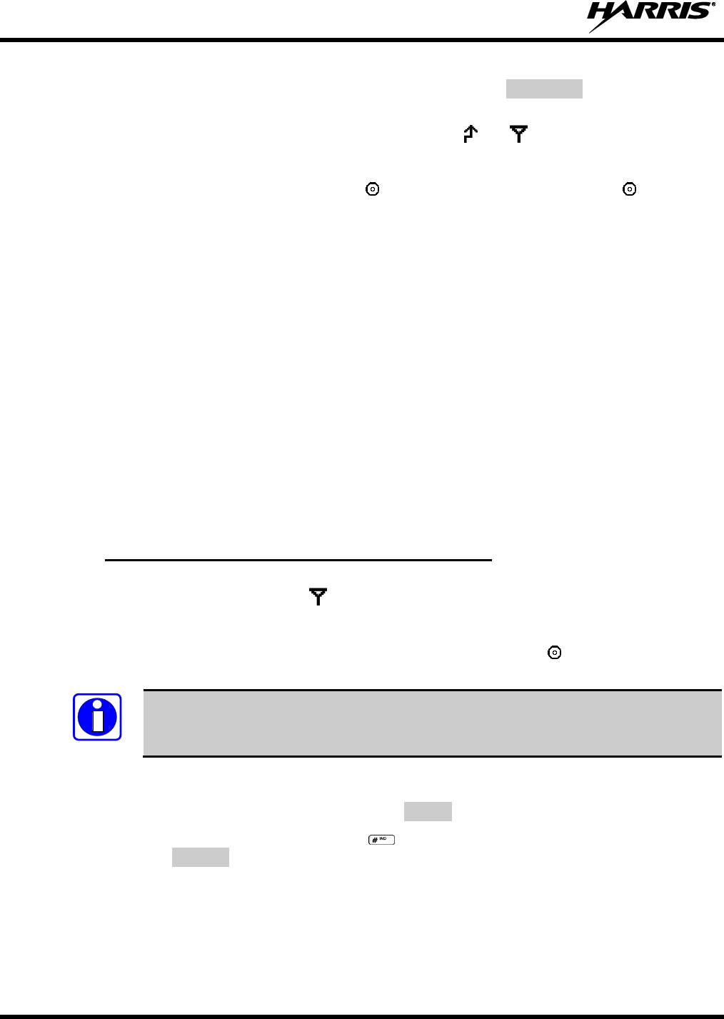
14221-1100-2010, Rev. E
86
2. When the working channel assignment is received, the radio sounds a single beep indicating the radio
has auto keyed (see Table 9-4) and is ready for voice transmission. *TXEMER* flashes on line two in
the display until the emergency is cleared.
3. Press PTT and speak into the microphone in a normal voice. and momentarily turn on.
4. Release PTT when the transmission is complete.
To clear the emergency, first press and hold the button. While continuing to hold the button, press
the EMERGENCY button. The radio must be programmed to clear emergencies.
9.24 STEALTH MODE
Press the button programmed for Stealth Mode operation to toggle Stealth Mode on or off. During Stealth
Mode, all buttons are disabled except PTT, the button programmed for Stealth operation, Emergency, and
Nuisance delete. The radio will receive and transmit when Stealth Mode is enabled.
The radio can be configured to disable any or all of the following during Stealth Mode:
LCD display
LED
Backlight
Side/alert tones
Stealth Mode can be configured to persist through a power cycle.
9.25 INDIVIDUAL CALLS
9.25.1 Receiving and Responding to an Individual Call
When the radio receives an individual call (a call directed only to the user's radio), it un-mutes on the
assigned working channel and displays . The first line on the display shows the logical ID number of
the unit sending the message, or the associated name if the ID number is found in the individual call list.
The radio can be programmed to ring when an individual call is received. If enabled, the ring begins five
seconds after the caller un-keys and will continue until the PTT button, the button, or the individual
call mode is entered.
The volume of the ring is adjustable through the volume control levels.
If a response is made by pressing the PTT to the call prior to the programmed call-back time-out, the call
will automatically be directed to the originating unit. If a response is not made before the call-back time-
out, the radio will return to normal receive display, and *WHC* will appear on the first line of the LCD.
To respond after the call-back time-out, press the key. The radio's display will show the callers ID on
the first line and WHCI=1 on the second line. Pressing the PTT button at this point will initiate an
individual call back to the original caller.
The radio stores the IDs of the last 10 callers in the Calls Received List as shown. Individual calls are
stored in the top half of the list (1-10) and Group calls are stored in the bottom half of the list (1-10). The
most recent call is stored in position 1, the second most recent call is stored in position 2, etc.
NOTE
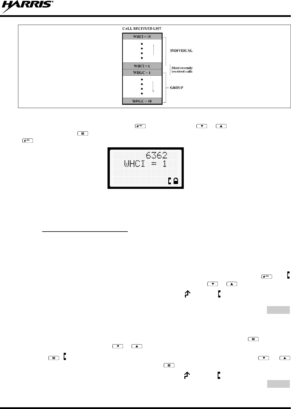
14221-1100-2010, Rev. E
87
Figure 9-14: Calls Received Lists
To access the Calls Received List, press the key twice. Use the or buttons to scroll through
the list. Pressing the key will display the time elapsed since the call was received. After pressing
the display will appear similar to Figure 9-15.
Figure 9-15: WHC Individual Call Display
Pressing the PTT will initiate an individual call to the displayed logical ID. Powering the radio off and on
will clear this list.
9.25.2 Sending an Individual Call
9.25.2.1 Pre-Stored Individual Calls
The following procedures describe how to initiate and complete a Pre-Stored Individual Call.
System Model Radio
1. To select a pre-stored individual phone number, enter the individual call mode using the key.
is displayed. Then scroll through the list of stored numbers using the or keys.
2. Press the PTT button; when the radio is clear to transmit, turns on, turns off, and the channel
access tone sounds. Line one shows the called individual's name if found in the list of stored
individuals or LID followed by the logical ID number of the unit being called. The message *INDV*
displays on line two.
Scan Model Radio
1. To select a pre-stored individual number, enter the menu mode by pressing the key. Scroll
through the mode list using the or buttons.
2. Press . is displayed. Scroll through the list of stored phone numbers using the or
buttons until the desired number is displayed. Press .
3. Press the PTT button; when the radio is clear to transmit turns on, turns off, and the channel
access tone sounds. Line one shows the called individual's name or LID. The message *INDV*
displays on line two.
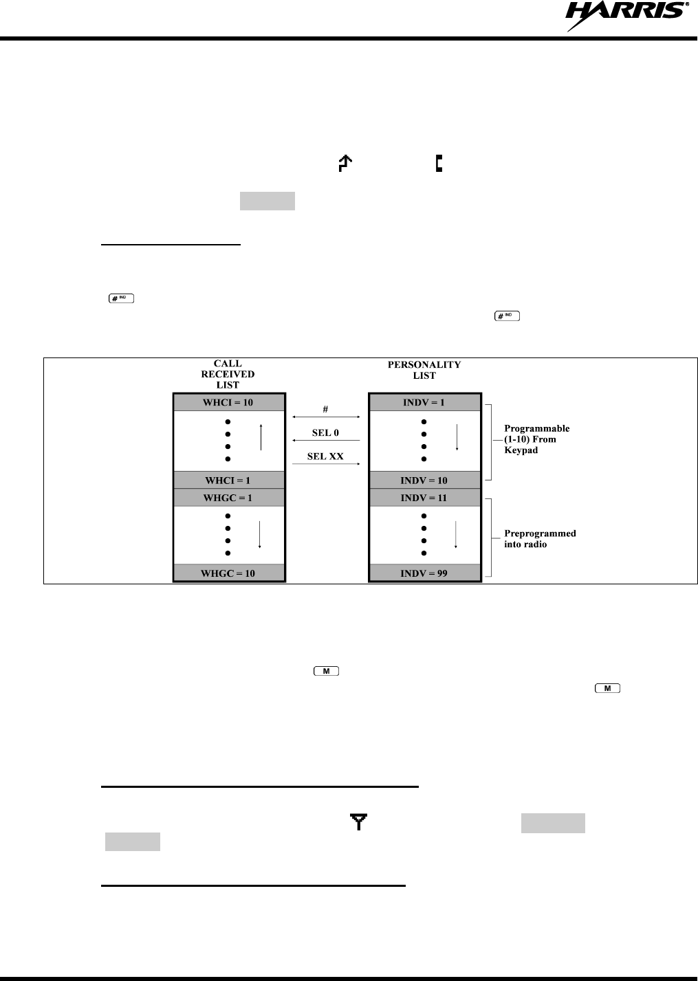
14221-1100-2010, Rev. E
88
9.25.2.2 Direct Dial Individual Calls (System Model Only)
1. The following procedure describes how to initiate and complete a Direct Dial Individual Call.
2. The individual call ID is not stored in the pre-stored list of call IDs but the individual unit ID is
known, it can be entered directly from the keypad.
3. Press and hold the PTT button to transmit. will turn on, will turn off, and the channel access tone
will sound. Line one shows the called individual's ID followed by the logical ID number of the unit
being called. The message *INDV* displays on line two. Proceed talking into the microphone.
9.25.3 Call Storage Lists
There are two lists available for call storage in the XG-75P series radios, the calls received list (1 - 10)
and the personality list (1 - 99 as defined by the user). When the individual call mode is entered by
pressing , the calls received list is available. The user can toggle to the personality list by selecting
any index other than 0 or toggle between the two lists by pressing the key. If wrap is enabled, the
calls received list wraps on itself and not into the other list.
Figure 9-16: Calls Received and Personality Lists
The saved call list shows all ten storage locations. If no calls have been received, the saved call list will be
empty and the pre-stored list will be available upon entering the individual call mode.
When in the saved call list, pressing the key toggles the time stamp on and off. The time stamp
indicates how long ago the call was received. When in the pre-stored list, pressing the key toggles
the Logical Identification (LID) on and off.
9.26 TELEPHONE INTERCONNECT CALLS
9.26.1 Receiving a Telephone Interconnect Call
When the radio receives a telephone interconnect call (a call directed only to the user's radio), it un-mutes
on the assigned working channel and displays . The first line displays *PHONE*. The second line
displays *INDV*. Proceed with the call. Press the PTT to talk, release the PTT to listen.
9.26.2 Sending a Telephone Interconnect Call
9.26.2.1 Pre-Stored Number
Use the following procedures to initiate and complete a Telephone Interconnect call.
14221-1100-2010, Rev. E
89
1. System Model: To select a previously stored phone number, press the key. Use the or
buttons to scroll through the list of stored numbers.
Scan Model: To select a previously stored phone number, press the key. Use the or
buttons to select the menu option PHN CALL. Press the key again then use the or
buttons to scroll through the list of pre-stored numbers.
2. Press and release the PTT button. When the radio is clear to transmit, turns on, turns off, and the
channel access tone sounds. Line one shows the accompanying name selected from the list of stored
numbers. The message *PHONE* appears on line two of the display. The radio then automatically
transmits the programmed number stored in the special call queue.
3. A telephone ring will be heard from the speaker. When someone answers the phone, press the PTT
button and speak into the microphone. Release the PTT button to listen to the callee. Unsuccessful
interconnect signaling returns the radio to the normal receive mode and the number remains displayed
until the special call is cleared or the time-out expires or another group or system is selected.
Terminate a call by pressing the button.
In half-duplex mode, only one person may talk at a time. The radio PTT button needs to
be pressed in order to communicate to the individual called and released for the individual
called to be heard.
9.26.2.2 Direct Dialing of Phone Calls (System Model Only)
1. If the phone number is not stored in the pre-stored list of phone numbers, but the phone number is
known, it can be entered directly from the keypad. Start by pressing the key, then enter the
required number from the keypad. Press and release the PTT button.
The last number directly entered can be recalled by first pressing then pressing the
PTT button.
2. A telephone ring can be heard from the speaker. When someone answers the phone, press and hold
the PTT button and speak into the microphone. Release the PTT button to listen to the individual
called. Unsuccessful interconnect signaling returns the radio to the normal receive mode and the
number remains displayed until the special call is cleared or the time-out expires or another group or
system is selected.
3. To terminate the call, momentarily press the button.
9.26.3 Dual-Tone Multi-Frequency: Overdial
Once the radio has established a connection to the public telephone system, it may be necessary to “over-
dial” more digits to access banking services, answering machines, credit card calls, or other types of
systems that require Dual-Tone Multi-Frequency (DTMF) access digits.
Overdial operation can also be used to initiate a telephone interconnect call via DTMF signaling if a dial
tone has already been accessed on the system. This method makes a telephone interconnect call while
operating in the conventional mode but will also function in trunked mode if a dial tone is directly
accessible.
Telephone numbers and other number sequences for overdialing can be stored in the phone list when
programming the radio. These numbers are accessed by pressing the key, then following the
selection mode rules. Perform the following procedures to access and dial these stored numbers.
NOTE
NOTE

14221-1100-2010, Rev. E
90
Scan Model Radio
1. Follow the procedure in Section 9.26.2 to establish a connection to the telephone system or consult
the system administrator for the procedure to access a dial tone on the trunked or conventional
system.
2. Enter selection mode first to enable entry of overdial numbers by pressing the button.
3. Follow the selection mode rules to call up a stored number from the phone list: Use the or
buttons to scroll through the list of stored numbers. is displayed. Press the PTT to send the overdial
sequence once. If the number needs to be transmitted again it must be selected or entered again (this
prevents unwanted numbers from being sent the next time the PTT button is pressed during the call).
Overdial select/entry mode remains active until the call is dropped, cleared, or is pressed. The
overdial select/entry mode can be re-entered if the call is still active by pressing .
System Model Radio
1. Follow the procedure in Section 9.26.2 to establish a connection to the telephone system or consult
the system administrator for the procedure to access a dial tone on the trunked or conventional
system.
2. Overdial numbers are transmitted using one of the following methods:
METHOD 1:
1. Enter the overdial selection mode by pressing the button.
2. Use the or buttons to scroll through the list of stored numbers. is
displayed. Press the PTT to send the overdial sequence once. If the number needs to
be transmitted again it must be selected or entered again (this prevents unwanted
numbers from being sent the next time the PTT button is pressed during the call).
Overdial select/entry mode remains active until the call is dropped, cleared, or is
pressed. The overdial select/entry mode can be re-entered if the call is still active by
pressing .
METHOD 2:
(System model radios only)
1. Enter the overdial selection mode by pressing the button.
2. Press and hold the PTT button while entering the overdial number sequence from the
keypad. This method sends DTMF tones during individual, telephone interconnect,
trunked group, or conventional channel calls. Press the PTT to send the overdial
sequence once. If the number needs to be transmitted again it must be selected or
entered again (this prevents unwanted numbers from being sent the next time the PTT
button is pressed during the call). Anytime the PTT button is pressed and held, the
keypad is enabled for DTMF entry.
Overdial select/entry mode remains active until the call is dropped, cleared, or is
pressed. The overdial select/entry mode can be re-entered if the call is still active by
pressing .
This overdial select/entry mode remains active until dropped, cleared, or is pressed. The overdial
select/entry mode can be re-entered if the call is still active by pressing the button.

14221-1100-2010, Rev. E
91
9.27 PRE-STORING INDIVIDUAL AND TELEPHONE INTERCONNECT
CALLS FROM THE KEYPAD
Individual Call ID numbers, telephone numbers, and other number sequences for overdialing are stored in
the special calls lists when programming the radio. The first ten entry locations of these lists can be
changed by the radio operator. The keypad is used when adding, changing, and storing numbers in these
entry locations.
Use the following procedure to store a number in one of the first ten entries of a special call list:
1. Press the or button to enter the individual call list or the phone call list. is displayed.
2. Scroll through the list using the or keys until one of the first ten entries is reached. NO
ENTRY is displayed if the location is empty.
3. Enter the desired number. If necessary, a pause can be entered by pressing and holding 0-9, , or
until an underscore appears in the display (telephone interconnect only). The individual call list
entries will accept up to 5 digits. The phone call list entries accept a combination of up to 31 digits
and pauses.
4. Press and hold the key until the display changes indicating that the number has been stored.
Repeat steps 1-4 to store additional numbers, to change numbers already stored, or to change the storage
location of a number.
9.28 STATUS/MESSAGE OPERATION
The Status and Message operations allow for the transmission of a pre-programmed status or a pre-
programmed message to an EDACS or P25 site. Each Status and Message is assigned an ID then cross-
referenced with the representative status condition (“Off Duty,” for example) or a message (“Call home”).
In addition, Status conditions can also be associated with a programmable Menu entry (required for
second method of transmitting a Status condition).
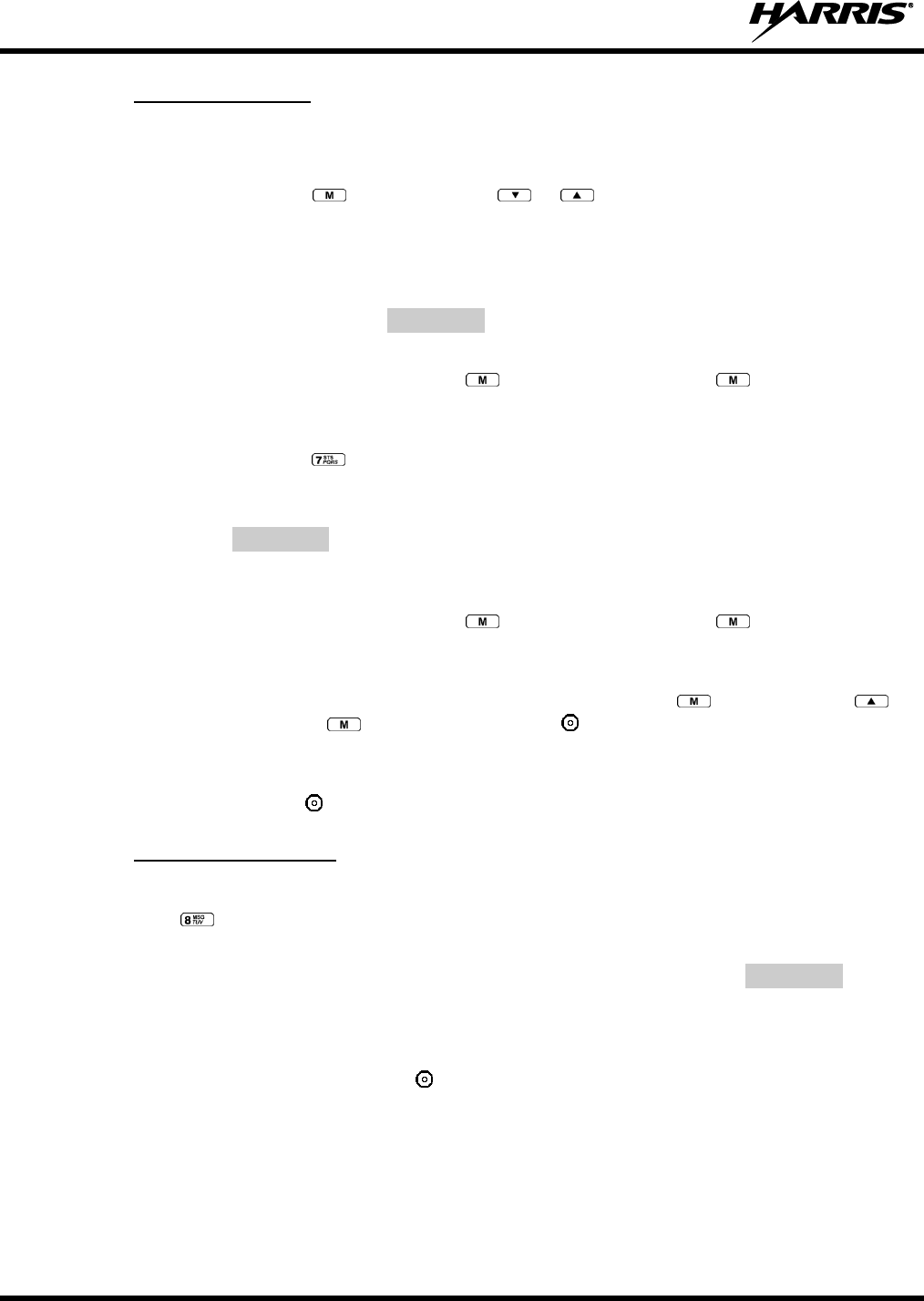
14221-1100-2010, Rev. E
92
9.28.1 Status Operation
System Model Radio
One of two methods can be used to transmit a status condition.
METHOD 1:
1. Press the key, then use the or buttons to scroll to the pre-programmed
status condition. STATUS and 0 through 9 pre-programmed status selections are
available from the menu.
2. If STATUS is selected, you need to enter the number of the status condition you
intend to transmit. If no status has been programmed for the selected number key, the
radio will display NO ENTRY. A valid selection will display the status for a pre-
programmed time.
After the time-out expires or the key has been pressed (the key will override the
time-out period), the status is selected and will be transmitted to the site or stored in the
radio memory where it can be polled by the site at a future time.
METHOD 2:
1. Press the key.
2. Press the corresponding pre-programmed 0 through 9 status condition key. If no
status has been programmed for the selected number key, the radio will display
NO ENTRY. A valid selection will permit the status condition to appear in the top
line of the display and the status ID to appear in the second line of the display for a
pre-programmed time.
After the time-out expires or the key has been pressed (the key will override the
time-out period), the status is selected and will be transmitted to the site or stored in the
radio memory where it can be polled by the site at a future time.
To view the currently selected status after it has been transmitted, press the key and then the key
to ramp to STATUS, press the key again and then the button prior to the time-out period. If the
status was not sent successfully to the site, the text associated with the status will flash in the display.
The status selection can be changed by pressing a different status key 0 through 9, or the status operation
can be cancelled by pressing . Both operations must be carried out prior to the time-out period.
9.28.2 Message Operation
The following method can be used to transmit a Message using the Message Operation.
1. Press the key.
2. Press the corresponding pre-programmed 0 through 9 pre-programmed “message” key. If no message
has been programmed for the selected number key, the radio will display NO ENTRY. A valid
selection will permit the message to appear in the top line of the display and the message ID to appear
in the second line of the display for a pre-programmed time.
The message selection can be changed by pressing a different message key 0 through 9, or the message
operation can be cancelled by pressing . Both operations must be carried out prior to the pre-
programmed time-out period.
9.29 DYNAMIC REGROUP OPERATION (EDACS)
Dynamic Regroup Operation permits multiple talk groups (up to eight) to be added to a radio via the
system manager. The radio must be pre-programmed to respond to regrouping. Dynamic regrouping will

14221-1100-2010, Rev. E
93
not be activated in a radio until the system manager sends an activation message. Each radio that receives
and acknowledges the regrouping instructions is successfully regrouped.
Pressing and holding the button for 2.5 seconds toggles the user into and out of the dynamic regroup
groupset. A double beep will sound for entry or exit. The display will indicate REGRP_0x where "x" is a
digit of 1 to 8 indicating the group (when dynamic regroup has been enabled by the user). If the radio is in
dynamic regroup and the user selects a group that has not been regrouped, the display will show NO
ENTRY. The radio will be prevented from transmitting and receiving calls in this condition except for
scanned groups.
After the time-out expires or the key has been pressed, the status is selected and is transmitted to the
site or stored in radio memory where it can be polled by the site at a future time.
If the pre-programmed groupset on the currently selected system contains an EMER/HOME group and
the radio is in dynamic regroup, the radio will declare the emergency on the currently selected dynamic
group.
9.30 MACRO KEY OPERATION
Macro key operation permits the user to accomplish a series of keystrokes with a single "macro"
keystroke. Each macro key is capable of executing up to twenty (20) keystrokes, to any push button input
(i.e., keypad keys, option buttons, etc.). Each macro key can be pre-programmed to activate when pressed
or when released. A macro key can also be pre-programmed to change the key stroke sequence the next
time the macro key is activated.
For detailed operation and assignment of macro keys, contact your communications supervisor or
administrator.
9.31 DATA COMMUNICATIONS
The XG-75P series portable radios permit both voice and data calls to be transmitted and received. The
radio can handle only one type of call at a time; however, either data or voice is selected transparently by
the operator through normal usage of the radio.
The radios can be connected to a Mobile Data Terminal (MDT) or to a host computer. Any RS-232
compatible device that supports the Radio Data Interface (RDI) protocol (Version 1.91 or greater) may be
connected to the radio. Support for MDTs or host computers is a programmable option per radio.
Additionally, radios may also be programmed for data only operation (no voice calls transmitted or
received).
9.31.1 Displays
The following will be displayed during data operation:
DATA T/R
Appears on top line of display when the radio is transmitting/receiving a data call.
DATA OFF
Appears on top line of display when the radio is in the data disabled state.
DATA ON
Appears for two seconds on top line of display when the radio is toggled to the data
enabled state.
9.31.2 Data Off Operation
The radio can be placed in the data disabled state by any of the following methods. When the data state is
disabled, DATA OFF appears on the top line of the display.
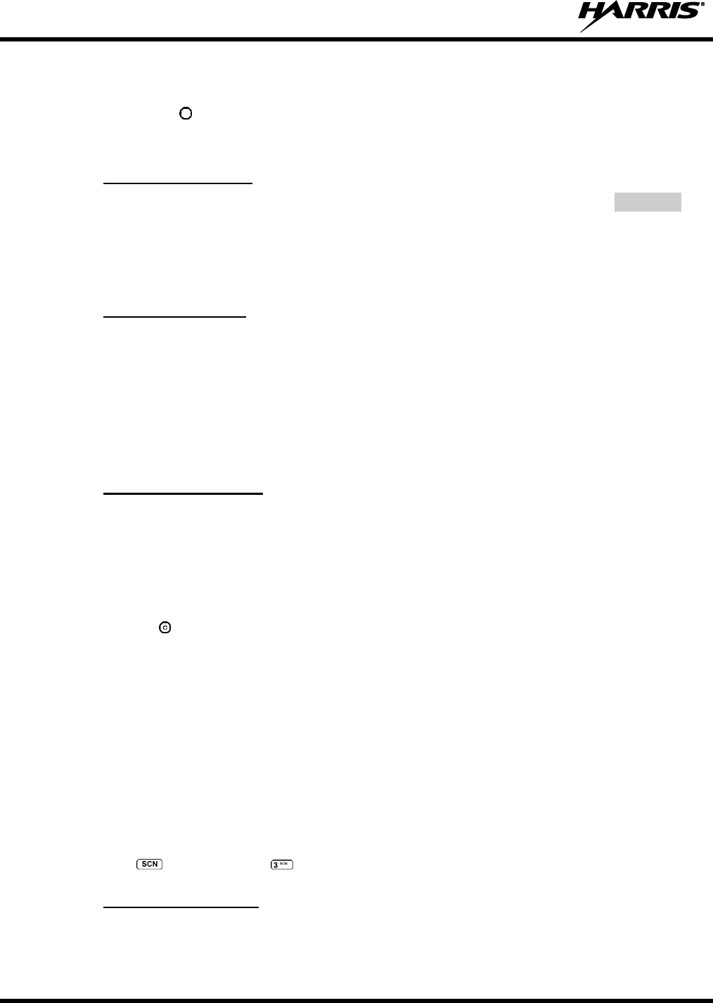
14221-1100-2010, Rev. E
94
Declaring an emergency (not to be used unless an actual emergency condition exists). Alert tone will
sound.
Pressing button (if pre-programmed as “no data” key). Alert tone will sound.
Pressing the pre-programmed “no data” key. Refer to previous bullet.
9.31.3 Data On Operation
The data state is enabled by one of the following (depending on how it was disabled). DATA ON will
appear on the top line in the display for two seconds; then the display will return to normal.
Pressing the pre-programmed “no data” (ND) key toggles data state on or off.
Clearing an emergency. This is valid only if the emergency caused “DATA OFF” operation.
9.31.4 Exiting Data Calls
Under normal conditions, the radio enters the scan lockout mode and returns to the control channel after
completion of a data call (transmit or receive). If, during a data call, one of the following operations
occurs, the data call is immediately terminated and the radio performs the desired function:
If the PTT is activated.
If an Emergency is declared by pressing the pre-programmed emergency button.
If a group or system is changed.
9.31.5 Scan Lockout Mode
Following the transmission or reception of a data call, if scan is enabled, scanning will stop temporarily.
There are two independent pre-programmed times associated with this mode; one after a received data
call and one after a transmitted data call. During this time, the scan indicator will flash to indicate that
scan is enabled but temporarily suspended. This condition typically returns to normal scan operation
when the pre-programmed time expires; however, the following operations and conditions will terminate
the scan lockout mode before the timeout has expired.
Pressing the button.
Pressing the PTT.
Changing a group or system.
Entering Telephone Interconnect mode.
Entering Individual call mode.
Receiving a new emergency assignment.
Declaring or clear an emergency.
Receiving an individual or phone call.
Receiving an Agency, Fleet, or System All Call.
Pressing (Scan model) or (System model) to toggle Scan on or off.
9.31.6 Data Lockout Mode
During the voice call scan hang time (pre-programmed) the radio does not receive data calls.

14221-1100-2010, Rev. E
95
9.32 SELECTIVE SIGNALING (CONVENTIONAL)
Selective signaling controls the muting and unmuting of the receive audio. This allows a user or
dispatcher to selectively call an individual radio or group of radios. The XG-75P portable radios support
selective signaling in Type 99 decode format.
9.32.1 Type 99 Operation
Type 99 is a conventional in-band, two-tone sequential signaling method. This conventional signaling
protocol controls the muting and unmuting of a radio. Type 99 encoded base stations, mobiles, or
portables can selectively call individual units or groups of units in a conventional system. Type 99 is
used in paging operations providing a dispatcher with the ability to selectively call a radio or a group of
radios. If Type 99 is enabled in the radio personality, the radio can decode Individual, Group, and
Supergroup Type 99 calls.
In a selective signaling environment, the XG-75P portable radios operate in one of two states, Monitor
mode or Selective Call mode.
In Monitor mode, Type 99 “OFF,” the decoder is disabled and all calls are heard by the user.
In Selective Call mode, Type 99 “ON,” the decoder is enabled and only calls intended for the user are
heard.
9.32.2 Type 99 with or without Channel Guard
Selective signaling operates with or without Channel Guard. If Channel Guard is enabled, the radio can
be programmed with an "And" or an "Or" option, determined by programming with T99 Mute Control.
If the "And" option is programmed, T99 calls require the correct selective signaling (T99 tone
sequence) AND the correct Channel Guard tones are heard by the user.
If the "Or" option is programmed, calls with the correct Channel Guard tones OR calls with the
correct T99 tone sequence and Channel Guard tones are heard by the user.
A radio operating in Selective Call mode that receives a selective call switches to the Monitor mode (after
decoding the T99 call) and the TX/RX LED flashes green. The TX/RX LED indicates whether the
channel has a carrier signal.
9.32.3 Resetting Type 99 after a Call
After decoding a Type 99 call, the radio operates in Monitor mode and all traffic on the channel is
audible. If the channel has Channel Guard, only the traffic with the radio's Channel Guard tone will be
heard.
To reset Type 99 operation, use one of the following methods:
Press the button.
Press the button, if enabled through programming to toggle Type 99 on/off.
Allow the "Auto-Reset" timer, if enabled through programming, to reset the Type 99 decoder.
9.32.4 Type 99 Disable after PTT
The radio may be programmed with the Type 99 Disable after PTT feature, which automatically disables
the Type 99 decoder after a transmission.
Use one of the methods outlined in the Section 9.32.3 to reset Type 99 operation.
14221-1100-2010, Rev. E
96
9.33 AUDIO PLAYBACK
Every call received by the radio is recorded in internal memory, overwriting the last recorded call. When
the PLAYBACK key is pressed, the last recording is replayed and any future recordings are stopped.
Pressing PLAYBACK again repeats the same recorded call. Pressing and holding the PLAYBACK key
until the tone sounds erases the recording and starts the recording of incoming calls again. If a call is
received while the recorded call is playing, the recorded call continues to play, rather than the received
audio. However, if a call is received and the recorded call is played back in close succession received
audio could mute call playback. This feature requires RPM R8A and later, and ECP R15A and later.
The PLAYBACK function must be programmed to a button on the radio via RPM.
9.34 RADIO TEXTLINK OPERATION
Radio TextLink provides a simple means of exchanging pre-defined, or “canned,” text messages. This
section describes how to send messages if the Radio TextLink feature is enabled.
9.34.1 Send TextLink Messages
1. Press to access the menu.
2. Press or to scroll through menu until SND MAIL is displayed. Press to select.
3. Press or to scroll through the pre-defined messages that scroll across the top of the display.
Press to select to select the desired message.
4. Press or to scroll through the list of available destination IDs and select the desired ID with
.
9.34.2 View Received TextLink Messages
Received Messages are listed in the order in which they are received (newest at the top). All messages
include the user LID along with the date and time stored/displayed. The mailbox can hold 16 messages at
a time. If a new Message arrives after the limit is reached, the new message overwrites the oldest
message.
1. Press to access the menu.
2. Press or to scroll through menu until RD MAIL is displayed. Press to select.
3. Scroll through the list of received messages using the or key.
4. Selecting a received message with the key will bring up a reply to sender option.
9.34.3 Delete TextLink Messages
Select DEL MAIL with the key to delete ALL messages in the inbox.
9.34.4 View the Current Time
Select TIME with the key to retrieve the current date and time.
NOTE

14221-1100-2010, Rev. E
97
9.35 VIEW GPS INFORMATION
If the GPS Speaker microphone is connected to the XG-75P, you can view your position and satellite
information via the GPS Menu. GPS requires an unobstructed view of the sky and the signal is greatly
diminished inside buildings, tunnels, heavily forested areas, etc. GPS may not work at all under some
conditions, especially in metal enclosures or buildings.
1. Press to access the menu.
2. Press or to scroll through menu until GPS is displayed and press to select.
3. Press or to scroll through available information screens.
9.36 CONTROL AND STATUS SERVICES
The XG-75P supports Control and Status services. These services allow the computer application to
monitor and control a radio. The Control and Status Services can be used from a locally-connected
Mobile Data Terminal (MDT) or a network MDT. In some cases, the radio can support both MDTs
simultaneously. However, priority is given to the local MDT.
The Radio Status Service allows an MDT or Fixed End System (FES) to receive real-time status updates
from a radio. An MDT sends Host Attach/Detach messages to the radio as UDP datagrams destined for
the UDP Service Address and Service UDP Port of the radio. All responses and asynchronous reports are
returned to the address and port of the requesting host. Refer to the ECP Control and Status Services
Feature Manual, 14221-7200-6040, for more information on this feature.

14221-1100-2010, Rev. E
98
10 PREVENTIVE MAINTENANCE
10.1 IMMERSIBLE PREVENTIVE MAINTENANCE
XG-75P radios labelled “immersible” (see Figure 10-1) require periodic testing using specialized
equipment to verify the radio’s watertight integrity.
To recertify the watertight integrity of the XG-75P portable radio, the radio must be inspected by a
service center authorized and certified by Harris to perform the necessary tests to verify the watertight
integrity.
The Harris Service Network includes company-owned service facilities as well as the capabilities of
service partners located throughout the world. We have over 250 Authorized Service Centers (ASC)
qualified to perform warranty repairs, installation and maintenance services. For a list of ASCs, contact
our Customer Care Center.
Preventive Maintenance for Immersion-Rated Radios
CAUTION
XG-75P radios with Immersion Option must be serviced by a service center
authorized and certified by Harris to perform the necessary tests to verify watertight
integrity. As part of a thorough preventive maintenance plan, Harris recommends
Immersion-Rated XG-75P radios are, at a minimum, tested and re-certified on an
annual basis. Harris further recommends that the radios be tested on or close to the
anniversary of the ship date printed on the Model Number label on the back of the
radio (see Figure 10-1).
Figure 10-1: Labels
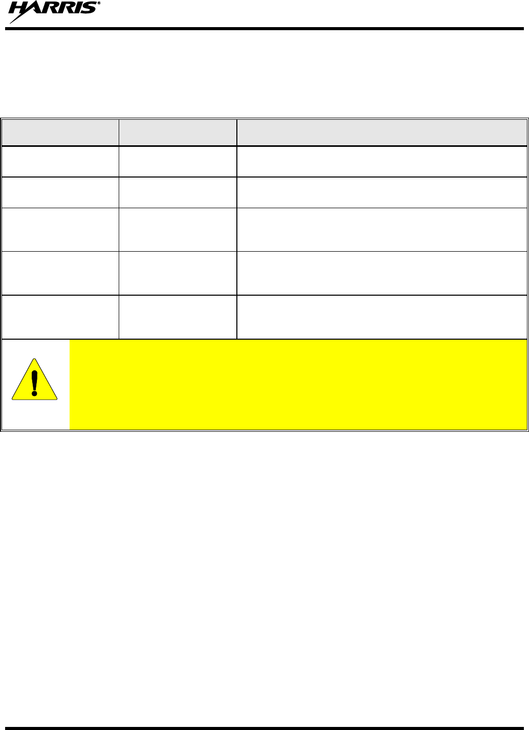
14221-1100-2010, Rev. E
99
10.2 BASIC TROUBLESHOOTING
Use Table 10-1 as a troubleshooting guide if the radio is not functioning properly. If additional assistance
is required, contact a qualified service technician or call Harris at 1-800-528-7711.
Table 10-1: Troubleshooting
SYMPTOM
POSSIBLE CAUSE
POSSIBLE SOLUTION
Radio will not turn
on.
Low battery charge.
Change the battery pack to a fully charged pack.
No Audio.
Speaker volume is
muted.
Increase the volume level.
Poor Audio.
User is in a poor
coverage area or not
on the network.
Move to a better coverage area.
Radio powers off for
no apparent reason.
Radio may be
experiencing very
low voltage.
Have the battery checked by an authorized technician.
Radio will not
transmit.
Radio may be out of
coverage area or
may be overheated.
Return to coverage area if possible. If overheated, let
radio cool before retrying transmission. Report this
failure to an authorized technician.
CAUTION
Though none of the above symptoms or solutions require disassembling the radio, this is a
reminder that Harris recommends the radio should only be disassembled by Harris-
authorized and certified service personnel. More importantly, if the radio is covered by
Immersion-Rated Option MAEV-PKGMR, then the radio must be serviced by Harris
authorized and certified service personnel. This is a requirement to maintain the watertight
integrity warranted under Immersion Option MAEV-PKGMR.

14221-1100-2010, Rev. E
100
11 CUSTOMER SERVICE
11.1 CUSTOMER CARE
If any part of the system equipment is damaged on arrival, contact the shipper to conduct an inspection
and prepare a damage report. Save the shipping container and all packing materials until the inspection
and the damage report are completed. In addition, contact the Customer Care center to make
arrangements for replacement equipment. Do not return any part of the shipment until you receive
detailed instructions from a Harris representative.
Contact the Customer Care center at http://www.pspc.harris.com/CustomerService or:
North America:
Phone Number: 1-800-368-3277
Fax Number: 1-321-409-4393
E-mail: PSPC_CustomerFocus@harris.com
International:
Phone Number: 1-434-455-6403
Fax Number: 1-321-409-4394
E-mail: PSPC_InternationalCustomerFocus@harris.com
11.2 TECHNICAL ASSISTANCE
The Technical Assistance Center's (TAC) resources are available to help with overall system operation,
maintenance, upgrades and product support. TAC is the point of contact when answers are needed to
technical questions.
Product specialists, with detailed knowledge of product operation, maintenance and repair provide
technical support via a toll-free (in North America) telephone number. Support is also available through
mail, fax and e-mail.
For more information about technical assistance services, contact your sales representative, or call the
Technical Assistance Center at:
North America: 1-800-528-7711
International: 1-434-385-2400
Fax: 1-434-455-6712
E-mail: PSPC_tac@harris.com

14221-1100-2010, Rev. E
101
12 WARRANTY
Please register this product within 10 days of purchase. Registration validates the warranty coverage, and
enables Harris to contact you in case of any safety notifications issued for this product.
Registration can be made on-line at the Customer Care center webpage:
http://www.pspc.harris.com/Service/Customerservice.aspx.
While on the webpage, please review the applicable battery and/or product warranty literature.

Public Safety and Professional Communications | www.pspc.harris.com
221 Jefferson Ridge Parkway | Lynchburg, VA USA 24501 | 1-800-528-7711

Product Safety Manual
14221-1100-2020
Rev. B, Sep/14
This booklet contains important safety information regarding
Specific Absorption Rate (SAR) and RF exposure limits included
in United States and international standards. Read the
information in this booklet before operating your radio.
XG-75P/XG-75Pe Series
Portable Radios

2 14221-1100-2020, Rev. B
REV
DATE
DESCRIPTION
-
Sep/11
Initial release.
A
Nov/11
Updated Table 1-2.
B
Sep/14
Added CE information. Added UHF-H band split to Table 1-1.
ACKNOWLEDGEMENTS
The software contained in this device is copyrighted by Harris Corporation. Unpublished rights
are reserved under the copyright laws of the United States.
This device is made under license under one or more of the following US patents: 4,590,473;
4,636,791; 5,148,482; 5,185,796; 5,271,017; 5,377,229; 4,716,407; 4,972,460; 5,502,767;
5,146,497; 5,164,986; 5,185,795; 5,226,084; 5,247,579; 5,491,772; 5,517,511; 5,630,011;
5,649,050; 5,701,390; 5,715,365; 5,754,974; 5,826,222; 5,870,405; 6,161,089; and 6,199,037 B1.
DVSI claims certain rights, including patent rights under aforementioned U.S. patents, and under
other U.S. and foreign patents and patents pending. Any use of this software or technology
requires a separate written license from DVSI.
CREDITS
Harris, EDACS, OpenSky, and assuredcommunications are registered trademarks and ProVoice is
a trademark of Harris Corporation.
RBRC and 1-800-8-BATTERY are registered trademarks of Rechargeable Battery Recycling
Corporation.
AMBE is a registered trademark and IMBE, AMBE+, and AMBE+2 are trademarks of Digital
Voice Systems, Inc.
All other product and brand names are trademarks, registered trademarks, or service marks of
their respective holders. NOTICE
The material contained herein is subject to U.S. export approval. No export or re-export is
permitted without written approval from the U.S. Government. Rated: EAR99; in accordance with
U.S. Dept. of Commerce regulations 15CFR774, Export Administration Regulations.
Information and descriptions contained herein are the property of Harris Corporation. Such
information and descriptions may not be copied or reproduced by any means, or disseminated or
distributed without the express prior written permission of Harris Corporation, PSPC Division,
221 Jefferson Ridge Parkway, Lynchburg, VA 24501.
This product conforms to the European Union WEEE Directive 2002/96/EC. Do not
dispose of this product in a public landfill. This product should be taken to a recycling
center at the end of its life.
The voice coding technology embodied in this product is protected by intellectual property rights
including patent rights, copyrights, and trade secrets of Digital Voice Systems, Inc. The user of
this technology is explicitly prohibited from attempting to decompile, reverse engineer, or
disassemble the Object Code, or in any other way convert the Object Code into human-readable
form.
Repairs to this equipment should be made only by an authorized service technician or facility
designated by the supplier. Any repairs, alterations, or substitution of recommended parts made
by the user to this equipment not approved by the manufacturer could void the user’s authority to
operate the equipment in addition to the manufacturer’s warranty.
This manual is published by Harris Corporation, without any warranty. Improvements and changes to this
manual necessitated by typographical errors, inaccuracies of current information, or improvements to programs
and/or equipment, may be made by Harris Corporation, at any time and without notice. Such changes will be
incorporated into new editions of this manual. No part of this manual may be reproduced or transmitted in any
form or by any means, electronic or mechanical, including photocopying and recording, for any purpose,
without the express written permission of Harris Corporation.
Copyright © 2011, 2014 Harris Corporation.
14221-1100-2020, Rev. B 3
This device is a RF transceiver intended for land mobile radio applications. The device may have
use restrictions, which require that the national authority be contacted for any system licensing
requirements, frequency use, allowable power level, etc.
4 14221-1100-2020, Rev. B

14221-1100-2020, Rev. B 5
Česky
[Czech]
Harris Corporation tímto prohlašuje, že tento XG-75P VHF
(136 – 174 MHz) UHF-L (378 – 470 MHz) je ve shodě se
základními požadavky a dalšími příslušnými ustanoveními
směrnice 1999/5/ES.
Dansk
[Danish]
Undertegnede Harris Corporation erklærer herved, at
følgende udstyr XG-75P VHF (136 – 174 MHz) UHF-L (378 –
470 MHz) overholder de væsentlige krav og øvrige relevante
krav i direktiv 1999/5/EF.
Deutsch
[German]
Hiermit erklärt Harris Corporation, dass sich das Gerät XG-
75P VHF (136 – 174 MHz) UHF-L (378 – 470 MHz) in
Übereinstimmung mit den grundlegenden Anforderungen und
den übrigen einschlägigen Bestimmungen der Richtlinie
1999/5/EG befindet.
Eesti
[Estonian]
Käesolevaga kinnitab Harris Corporation seadme XG-75P
VHF (136 – 174 MHz) UHF-L (378 – 470 MHz) vastavust
direktiivi 1999/5/EÜ põhinõuetele ja nimetatud direktiivist
tulenevatele teistele asjakohastele sätetele.
English
Hereby, Harris Corporation, declares that this XG-75P VHF
(136 – 174 MHz) UHF-L (378 – 470 MHz) is in compliance
with the essential requirements and other relevant provisions
of Directive 1999/5/EC.
Español
[Spanish]
Por medio de la presente Harris Corporation declara que el
XG-75P VHF (136 – 174 MHz) UHF-L (378 – 470 MHz)
cumple con los requisitos esenciales y cualesquiera otras
disposiciones aplicables o exigibles de la Directiva
1999/5/CE.
Ελληνική
[Greek]
ΜΕ ΤΗΝ ΠΑΡΟΥΣΑ Harris Corporation ΔΗΛΩΝΕΙ ΟΤΙ XG-
75P VHF (136 – 174 MHz) UHF-L (378 – 470 MHz)
ΣΥΜΜΟΡΦΩΝΕΤΑΙ ΠΡΟΣ ΤΙΣ ΟΥΣΙΩΔΕΙΣ ΑΠΑΙΤΗΣΕΙΣ
ΚΑΙ ΤΙΣ ΛΟΙΠΕΣ ΣΧΕΤΙΚΕΣ ΔΙΑΤΑΞΕΙΣ ΤΗΣ ΟΔΗΓΙΑΣ
1999/5/ΕΚ.
Français
[French]
Par la présente Harris Corporation déclare que l'appareil XG-
75P VHF (136 – 174 MHz) UHF-L (378 – 470 MHz) est
conforme aux exigences essentielles et aux autres
dispositions pertinentes de la directive 1999/5/CE.
Italiano
[Italian]
Con la presente Harris Corporation dichiara che questo XG-
75P VHF (136 – 174 MHz) UHF-L (378 – 470 MHz) è
conforme ai requisiti essenziali ed alle altre disposizioni
pertinenti stabilite dalla direttiva 1999/5/CE.
Latviski
[Latvian]
Ar šo Harris Corporation deklarē, ka UHF-L XG-75P (378 –
470 MHz) atbilst Direktīvas 1999/5/EK būtiskajām prasībām
un citiem ar to saistītajiem noteikumiem.
Lietuvių
[Lithuanian]
Šiuo Harris Corporation deklaruoja, kad šis XG-75P VHF
(136 – 174 MHz) UHF-L (378 – 470 MHz) atitinka esminius
reikalavimus ir kitas 1999/5/EB Direktyvos nuostatas.

6 14221-1100-2020, Rev. B
Nederlands
[Dutch]
Hierbij verklaart Harris Corporation dat het toestel XG-75P
VHF (136 – 174 MHz) UHF-L (378 – 470 MHz) in
overeenstemming is met de essentiële eisen en de andere
relevante bepalingen van richtlijn 1999/5/EG.
Malti
[Maltese]
Hawnhekk, Harris Corporation, jiddikjara li dan XG-75P VHF
(136 – 174 MHz) UHF-L (378 – 470 MHz) jikkonforma mal-
ħtiġijiet essenzjali u ma provvedimenti oħrajn relevanti li
hemm fid-Dirrettiva 1999/5/EC.
Magyar
[Hungarian]
Alulírott, Harris Corporation nyilatkozom, hogy a XG-75P
VHF (136 – 174 MHz) UHF-L (378 – 470 MHz) megfelel a
vonatkozó alapvetõ követelményeknek és az 1999/5/EC
irányelv egyéb elõírásainak.
Polski
[Polish]
Niniejszym Harris Corporation oświadcza, że XG-75P VHF
(136 – 174 MHz) UHF-L (378 – 470 MHz) jest zgodny z
zasadniczymi wymogami oraz pozostałymi stosownymi
postanowieniami Dyrektywy 1999/5/EC.
Português
[Portuguese]
Harris Corporation declara que este XG-75P VHF (136 – 174
MHz) UHF-L (378 – 470 MHz) está conforme com os
requisitos essenciais e outras disposições da Directiva
1999/5/CE.
Slovensko
[Slovenian]
Harris Corporation izjavlja, da je ta XG-75P VHF (136 – 174
MHz) UHF-L (378 – 470 MHz) v skladu z bistvenimi
zahtevami in ostalimi relevantnimi določili direktive
1999/5/ES.
Slovensky
[Slovak]
Harris Corporation týmto vyhlasuje, že XG-75P VHF (136 –
174 MHz) UHF-L (378 – 470 MHz) spĺňa základné
požiadavky a všetky príslušné ustanovenia Smernice
1999/5/ES.
Suomi
[Finnish]
Harris Corporation vakuuttaa täten että XG-75P VHF (136 –
174 MHz) UHF-L (378 – 470 MHz) tyyppinen laite on
direktiivin 1999/5/EY oleellisten vaatimusten ja sitä koskevien
direktiivin muiden ehtojen mukainen.
Svenska
[Swedish]
Härmed intygar Harris Corporation att denna XG-75P VHF
(136 – 174 MHz) UHF-L (378 – 470 MHz) står I
överensstämmelse med de väsentliga egenskapskrav och
övriga relevanta bestämmelser som framgår av direktiv
1999/5/EG.
Íslenska
[Icelandic]
Hér með lýsir Harris Corporation yfir því að XG-75P VHF
(136 – 174 MHz) UHF-L (378 – 470 MHz) er í samræmi við
grunnkröfur og aðrar kröfur, sem gerðar eru í tilskipun
1999/5/EC.
Norsk
[Norwegian]
Harris Corporation erklærer herved at utstyret XG-75P VHF
(136 – 174 MHz) UHF-L (378 – 470 MHz) er i samsvar med
de grunnleggende krav og øvrige relevante krav i direktiv
1999/5/EF.

14221-1100-2020, Rev. B 7
TABLE OF CONTENTS Page
1. REGULATORY AND SAFETY INFORMATION ........................... 8
1.1 SAFETY SYMBOL CONVENTIONS ........................................ 8
1.2 SAFETY TRAINING INFORMATION ...................................... 9
1.3 OPERATING TIPS .................................................................... 11
2. RENSEIGNEMENTS SUR LA RÉGLEMENTATION ET SÉCURITÉ
14
2.1 CONVENTIONS SUR LES SYMBOLES DE SÉCURITÉ ....... 14
2.2 RENSEIGNEMENTS SUR LA FORMATION SUR LA SÉCURITÉ
.................................................................................................. 15
2.3 INTERFÉRENCE DES RADIOFRÉQUENCES ....................... 17
2.4 CONSEILS D’UTILISATION ................................................... 17
3. OPTIONS AND ACCESSORIES ...................................................... 19
4. BATTERY PACKS ............................................................................ 20
4.1 CONDITIONING NIMH BATTERY PACKS........................... 20
4.2 CONDITIONING LI-ION OR LI-POLY PACKS ..................... 21
4.3 STORING LI-ION BATTERY PACKS ..................................... 21
4.4 ADDITIONAL INFORMATION ............................................... 21
4.5 BATTERY DISPOSAL .............................................................. 21
5. IMMERSIBLE XG-75P PREVENTIVE MAINTENANCE ........... 22
6. TECHNICAL ASSISTANCE ............................................................ 22
7. WARRANTY ...................................................................................... 23
Harris Corporation, Public Safety and Professional Communications (PSPC) Business continually
evaluates its technical publications for completeness, technical accuracy, and organization. You
can assist in this process by submitting your comments and suggestions to the following:
Harris Corporation
PSPC Business or fax your comments to: 1-434-455-6851
Technical Publications
221 Jefferson Ridge Parkway or e-mail us at: PSPC_techpubs@harris.com
Lynchburg, VA 24501
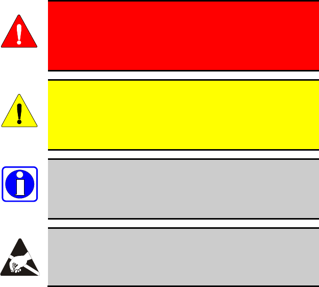
8 14221-1100-2020, Rev. B
1. REGULATORY AND SAFETY INFORMATION
1.1 SAFETY SYMBOL CONVENTIONS
The following conventions are used to alert the user to general safety
precautions that must be observed during all phases of operation, service, and
repair of this product. Failure to comply with these precautions or with
specific warnings elsewhere violates safety standards of design, manufacture,
and intended use of the product. Harris assumes no liability for the customer's
failure to comply with these standards.
WARNING
The WARNING symbol calls attention to a procedure,
practice, or the like, which, if not correctly performed or
adhered to, could result in personal injury. Do not proceed
beyond a WARNING symbol until the conditions identified
are fully understood or met.
CAUTION
The CAUTION symbol calls attention to an operating
procedure, practice, or the like, which, if not performed
correctly or adhered to, could result in a risk of danger, damage
to the equipment, or severely degrade the equipment
performance.
NOTE
The NOTE symbol calls attention to supplemental
information, which may improve system performance or
clarify a process or procedure.
The ESD symbol calls attention to procedures, practices, or the
like, which could expose equipment to the effects of Electro-
Static Discharge. Proper precautions must be taken to prevent
ESD when handling circuit modules.

14221-1100-2020, Rev. B 9
1.2 SAFETY TRAINING INFORMATION
WARNING
The Harris Corporation XG-75 portable radio generates
RF electromagnetic energy during transmit mode. This
radio is designed for and classified as “Occupational Use
Only,” meaning it must be used only during the course of
employment by individuals aware of the hazards and the
ways to minimize such hazards. This radio is NOT
intended for use by the “General Population” in an
uncontrolled environment.
The XG-75P portable radio has been tested and complies with the FCC RF
exposure limits for “Occupational Use Only.” In addition, this radio complies
with the following Standards and Guidelines with regard to RF energy and
electromagnetic energy levels and evaluation of such levels for exposure to
humans:
FCC OET Bulletin 65 Edition 97-01 Supplement C, Evaluating
Compliance with FCC Guidelines for Human Exposure to Radio
Frequency Electromagnetic Fields.
American National Standards Institute (C95.1 – 1992), IEEE Standard for
Safety Levels with Respect to Human Exposure to Radio Frequency
Electromagnetic Fields, 3 kHz to 300 GHz.
American National Standards Institute (C95.3 – 1992), IEEE
Recommended Practice for the Measurement of Potentially Hazardous
Electromagnetic Fields – RF and Microwave.
DIRECTIVE 2004/40/EC OF THE EUROPEAN PARLIAMENT AND
OF THE COUNCIL of 29 April 2004 on the minimum health and safety
requirements regarding the exposure of workers to the risks arising from
physical agents (electromagnetic fields) and amended by:
Directive 2007/30/EC of the European Parliament and of the Council of
20 June 2007
Directive 2008/46/EC of the European Parliament and of the Council of
23 April 2008
Regulation (EC) No 1137/2008 of the European Parliament and of the
Council of 22 October 2008
Directive 2012/11/EU of the European Parliament and of the Council of
19 April 2012
10 14221-1100-2020, Rev. B
1.2.1 RF Exposure Guidelines
CAUTION
To ensure that exposure to RF electromagnetic energy is
within the FCC allowable limits for occupational use
and/or the exposure limit values in Annex A of EU
Directive 2004/40/EC, always adhere to the following
guidelines:
DO NOT operate the radio without a proper antenna attached, as this may
damage the radio and may also cause the FCC RF exposure limits and/or
the exposure limit values in Annex A of EU Directive 2004/40/EC to be
exceeded. A proper antenna is the antenna supplied with this radio by
Harris or an antenna specifically authorized by Harris Corporation for use
with this radio.
DO NOT transmit for more than 50% of total radio use time (“50% duty
cycle”). Transmitting more than 50% of the time can cause FCC RF
exposure compliance requirements and/or the exposure limit values in
Annex A of EU Directive 2004/40/EC to be exceeded. The radio is
transmitting when the “TX” indicator appears in the display. The radio
will transmit by pressing the “PTT” (Push-To-Talk) button.
ALWAYS transmit using low power when possible. In addition to
conserving battery charge, low power can reduce RF exposure.
ALWAYS use Harris authorized accessories (antennas, batteries, belt
clips, speaker/mics, etc). Use of unauthorized accessories may cause the
FCC Occupational/Controlled Exposure RF compliance requirements
and/or the exposure limit values in Annex A of EU Directive 2004/40/EC
to be exceeded.
As noted in Table 1-1, ALWAYS keep the housing of the transmitter AT
LEAST 1.6 cm (0.63 inches) from the body and at least 2.5 cm (1.00
inch) from the face when transmitting to ensure FCC RF exposure
compliance requirements and/or the exposure limit values in Annex A of
EU Directive 2004/40/EC are not exceeded. However, to provide the best
sound quality to the recipients of your transmission, Harris recommends
you hold the microphone at least 5 cm (2 inches) from your mouth, and
slightly off to one side.
Table 1-1: RF Exposure Compliance Tested Distances
RADIO FREQUENCY
BAND
TESTED DISTANCES
(worst case scenario)
Body
Face
VHF (136 - 174 MHz)
1.6 cm
2.5 cm
UHF-L (378-470 MHz)
1.6 cm
2.5 cm
700-800 MHz
1.6 cm
2.5 cm
UHF-H (450-522 MHz)
1.6 cm
2.5 cm

14221-1100-2020, Rev. B 11
Table 1-2: Distance from Body for Different Carrying Options
CARRYING CONFIGURATION
TESTED DISTANCES (WORST
CASE FROM BODY)
Belt Clip
1.8 cm
Leather Case with Belt Loop
5.2 cm
Nylon Case with Belt Loop
4.5 cm
Shoulder Strap with D-clip
3.0 cm
Speaker-microphone with
antenna
1.6 cm
The information in this section provides the information needed to make the
user aware of a RF exposure, and what to do to assure that this radio operates
within the FCC RF exposure limits and/or the exposure limit values in Annex
A of EU Directive 2004/40/EC.
1.2.2 Electromagnetic Interference/Compatibility
During transmissions, Harris radios generate RF energy that can possibly
cause interference with other devices or systems. To avoid such interference,
turn off the radios in areas where signs are posted to do so. DO NOT operate
the transmitter in areas that are sensitive to electromagnetic radiation such as
hospitals, aircraft, and blasting sites.
1.2.3 Radio Frequency Interference
1.2.3.1 Part 15
This device complies with Part 15 of the FCC Rules. Operation is subject to
the following two conditions:
1. This device may not cause harmful interference, and
2. This device must accept any interference received, including interference
that may cause undesired operation.
1.2.3.2 Industry Canada
This device complies with Industry Canada license-exempt RSS standard(s).
Operation is subject to the following two conditions: (1) this device may not
cause interference, and (2) this device must accept any interference, including
interference that may cause undesired operation of the device.
1.3 OPERATING TIPS
Antenna location and condition are important when operating a portable radio.
Operating the radio in low lying areas or terrain, under power lines or bridges,
inside of a vehicle or in a metal framed building can severely reduce the range
of the unit. Mountains can also reduce the range of the unit.
12 14221-1100-2020, Rev. B
In areas where transmission or reception is poor, some improvement may be
obtained by ensuring the antenna is vertical. Moving a few yards in another
direction or moving to a higher elevation may also improve communications.
Vehicular operation can be aided with the use of an externally mounted
antenna.
Battery condition is another important factor in the trouble free operation of a
portable radio. Always properly charge the batteries.
1.3.1 Efficient Radio Operation
Keep the antenna in a vertical position when receiving or transmitting a
message.
WARNING
Do NOT hold onto the antenna when the radio is powered
on.
1.3.2 Antenna Care and Replacement
WARNING
Always keep the antenna at least 1.6 cm (0.63 inches) from
the body and at least 2.5 cm (1.00 inch) from the face when
transmitting to ensure FCC RF exposure compliance
requirements are not exceeded.
WARNING
Do not use the portable radio with a damaged or missing
antenna. A minor burn may result if skin comes into
contact with a damaged antenna. Replace a damaged
antenna immediately. Operating a portable radio with the
antenna missing could cause personal injury, damage the
radio, and may violate FCC regulations.
WARNING
Use only supplied or approved antennas. Use of
unauthorized antennas, modifications, or attachments
could cause damage to the radio unit and may violate FCC
regulations.
1.3.3 Electronic Devices
CAUTION
RF energy from portable radios may affect some electronic
equipment. Most modern electronic equipment in cars,
hospitals, homes, etc. are shielded from RF energy. However,
in areas in which you are instructed to turn off two-way radio
equipment, always observe the rules. If in doubt, turn it off!

14221-1100-2020, Rev. B 13
1.3.4 Aircraft
WARNING
Always turn off a portable radio before boarding any
aircraft!
Use it on the ground only with crew permission.
DO NOT use while in-flight!!
1.3.5 Electric Blasting Caps
WARNING
To prevent accidental detonation of electric blasting caps,
DO NOT use two-way radios within 1000 feet of blasting
operations. Always obey the "Turn Off Two-Way Radios"
signs posted where electric blasting caps are being used.
(OSHA Standard: 1926.900)
1.3.6 Potentially Explosive Atmospheres
WARNING
Areas with potentially explosive atmospheres are often,
but not always, clearly marked. These may be fuelling
areas, such as gas stations, fuel or chemical transfer or
storage facilities, and areas where the air contains
chemicals or particles, such as grain, dust, or metal
powders.
Sparks in such areas could cause an explosion or fire
resulting in bodily injury or even death.
Turn OFF two-way radios when in any area with a
potentially explosive atmosphere. It is rare, but not
impossible that a radio or its accessories could generate
sparks.

14 14221-1100-2020, Rev. B
2. RENSEIGNEMENTS SUR LA
RÉGLEMENTATION ET SÉCURITÉ
2.1 CONVENTIONS SUR LES SYMBOLES DE
SÉCURITÉ
Les conventions suivantes sont utilisées dans le présent manuel pour avertir
l’utilisateur des précautions générales de sécurité qui doivent être observées
pendant toutes les phases d’opération, d’entretien et de réparation de ce
produit. Le non-respect de ces précautions ou d’avertissements précisés
ailleurs enfreint les normes de sécurité de la conception, de la fabrication et de
l’utilisation prévue du produit. Harris n’assume aucune responsabilité pour le
non-respect de ces normes par le client.
MISE EN GARDE
Le symbole MISE EN GARDE attire l’attention sur une
procédure ou une pratique qui, si elle n’est pas
correctement effectuée ou observée, pourrait entraîner
une blessure personnelle. Ne pas poursuivre au-delà d’un
symbole de MISE EN GARDE avant que les conditions
identifiées soient complètement comprises ou satisfaites.
AVERTISSEMENT
Le symbole AVERTISSEMENT attire l’attention sur une
procédure ou une pratique opérationnelle qui, si elle n’est pas
correctement effectuée ou observée, pourrait entraîner un bris
d’équipement ou une importante baisse de rendement de
l’équipement.
REMARQUE
Le symbole REMARQUE attire l’attention sur des
renseignements supplémentaires qui peuvent améliorer le
rendement du système ou clarifier un processus ou une
procédure.

14221-1100-2020, Rev. B 15
2.2 RENSEIGNEMENTS SUR LA FORMATION SUR
LA SÉCURITÉ
MISE EN GARDE
La radio portative Harris XG-75P produit de l’énergie
électromagnétique des RF lorsqu’en mode de
transmission. Cette radio est conçue et classée pour une
« Utilisation professionnelle seulement », ce qui signifie
qu’elle ne doit être utilisée que dans le cadre d’un emploi
par des individus conscients des risques et des moyens de
limiter ceux-ci. Cette radio N’EST PAS conçue pour une
utilisation par la « Population générale » dans un
environnement non contrôlé.
La radio portative XG-75P a été testée et est conforme aux limites
d’exposition aux RF de la FCC pour une « Utilisation professionnelle
seulement ». De plus, cette radio Harris est conforme aux normes et directives
suivantes quant à l’énergie des RF et aux niveaux d’énergie
électromagnétique, ainsi qu’à l’évaluation de ces niveaux pour l’exposition
aux humains :
Bulletin 65 du OET de la FCC, édition 97-01, supplément C, portant sur
l’évaluation de la conformité aux directives de la FCC quant à
l’exposition humaine aux champs électromagnétiques des
radiofréquences.
American National Standards Institute (C95.1 – 1992), norme de l’IEEE
sur les niveaux sécuritaires d’exposition humaine aux champs
électromagnétiques des radiofréquences, 3 kHz à 300 GHz.
American National Standards Institute (C95.3 – 1992), pratique
recommandée par l’IEEE pour la mesure des champs électromagnétiques
potentiellement dangereux – RF et micro-ondes.
2.2.1 Directives sur l’exposition aux RF
AVERTISSEMENT
Pour s’assurer que l’exposition à l’énergie électromagnétique
des RF se situe dans les limites acceptables de la FCC pour
l’utilisation professionnelle, respectez toujours les directives
suivantes :
N’utilisez PAS la radio sans qu’une antenne appropriée y soit connectée,
car ceci peut endommager la radio et également causer un dépassement
des limites d’exposition aux RF de la FCC. Une antenne appropriée est
celle fournie par Harris avec cette radio, ou une antenne spécifiquement
autorisée par Harris pour être utilisée avec cette radio.

16 14221-1100-2020, Rev. B
Ne transmettez PAS pendant plus de 50 % de la durée d’utilisation totale
de la radio (« cycle de service de 50 % »). La transmission pendant plus
de 50 % du temps peut causer un dépassement des exigences de
conformité de la FCC en matière d’exposition aux RF. La radio transmet
lorsque l’indicateur « TX » apparaît sur l’affichage. La radio transmet
lorsqu’on appuie sur le bouton « PTT » (bouton de microphone).
Transmettez TOUJOURS en basse puissance lorsque possible. En plus de
préserver la charge de la pile, une faible puissance réduit l’exposition aux
RF.
Utilisez TOUJOURS des accessoires autorisés Harris (antennes, piles,
pinces de ceinture, haut-parleurs/micros, etc.). L’utilisation d’accessoires
non autorisés peut entraîner un dépassement des exigences de conformité
pour une exposition aux RF professionnelle ou contrôlée de la FCC.
(Reportez-vous à Tableau 2-1.)
Tel qu’indiqué dans Tableau 2-1, conservez TOUJOURS l’appareil et son
antenne à AU MOINS 1,6 cm (0,63 po) du corps, et à au moins 2,5 cm
(1,0 po) du visage pendant la transmission, pour vous assurer de ne pas
dépasser les exigences de conformité de la FCC en matière d’exposition
aux RF. Cependant, pour offrir la meilleure qualité sonore aux auditeurs
de votre transmission, Harris recommande de tenir le microphone à au
moins 5 cm (2 po) de votre bouche et légèrement déplacé sur un côté.
Tableau 2-1: Distances de test de conformité des expositions aux RF
RADIOFRÉQUENCES
DISTANCES TESTÉES
(pire des scénarios)
Corps
Visage
VHF (136 - 174 MHz)
1,6 cm
2,5 cm
UHF-L (378-470 MHz)
1,6 cm
2,5 cm
700-800 MHz
1,6 cm
2,5 cm
UHF-H (450-522 MHz)
1,6 cm
2,5 cm
Tableau 2-2: Distance du corps pour différentes options de transport
CONFIGURATION DE TRANSPORT
DISTANCES TESTÉES
(DISTANCE MINIMALE AU
CORPS)
Attache de ceinture
1,8 cm
Étui en cuir avec ganse de ceinture
5,2 cm
Étui en nylon avec ganse de ceinture
4,5 cm
Bandoulière avec attache en « D »
3,0 cm
Microphone / Haut-parleur avec antenne
1,6 cm

14221-1100-2020, Rev. B 17
Dans cette section figurent les renseignements nécessaires pour sensibiliser
l’utilisateur à l’exposition aux RF et sur ce qu’il faut faire pour s’assurer que
cette radio fonctionne dans les limites d’exposition aux RF de la FCC.
2.2.2 Interférence/Compatibilité Électromagnétique
Pendant les transmissions, cette radio Harris produit de l’énergie des RF qui
peut causer de l’interférence avec d’autres appareils ou systèmes. Pour éviter
de telles interférences, fermez la radio dans les zones où il est indiqué de le
faire. N’utilisez PAS le transmetteur dans des zones sensibles aux radiations
électromagnétiques, comme les hôpitaux, les avions et les sites de détonation.
2.3 INTERFÉRENCE DES RADIOFRÉQUENCES
2.3.1 Partie 15 de la FCC
Cet appareil est conforme à la Partie 15 de la réglementation de la FCC. Le
fonctionnement est soumis aux deux conditions suivantes :
1. Cet appareil ne doit pas causer une interférence nuisible; et
2. Cet appareil doit accepter toute interférence reçue, y compris une
interférence qui peut causer un fonctionnement non souhaité.
2.3.2 Industrie Canada
Cet appareil est conforme aux normes RSS exemptées de licence d’Industrie
Canada. Le fonctionnement est soumis aux deux conditions suivantes : (1) cet
appareil ne doit pas causer d’interférence et (2) cet appareil doit accepter toute
interférence, y compris une interférence qui peut causer un fonctionnement
non souhaité de l’appareil.
2.4 CONSEILS D’UTILISATION
L’emplacement et l’état de l’antenne sont importants pour l’utilisation d’une
radio portative. L’utilisation de la radio dans des zones de faible élévation,
sous des lignes électriques ou des ponts, à l’intérieur d’un véhicule ou dans un
immeuble à ossature métallique, peut réduire la portée de l’appareil de
manière considérable. Les montagnes peuvent également réduire la portée de
l’unité.
Dans les zones où la transmission ou la réception est insatisfaisante, certaines
améliorations peuvent être obtenues en s’assurant que l’antenne est verticale.
Se déplacer de quelques mètres dans une autre direction ou à un emplacement
plus élevé peut également améliorer les communications. L’utilisation d’une
antenne fixée à l’extérieur peut faciliter le fonctionnement dans un véhicule.
L’état de la pile est un autre facteur important d’une utilisation sans tracas
d’une radio portative. Chargez toujours correctement la pile.
18 14221-1100-2020, Rev. B
2.4.1 Utilisation Efficace de la Radio
Gardez l’antenne dans une position verticale pendant la réception ou la
transmission d’un message.
MISE EN GARDE
Ne tenez PAS l’antenne lorsque la radio est allumée!
2.4.1.1 Entretien Et Remplacement De L’antenne
MISE EN GARDE
N’utilisez pas la radio portative si son antenne est
endommagée ou absente. Une brûlure légère peut se
produire au contact d’une antenne endommagée avec la
peau. Remplacez immédiatement une antenne
endommagée. L’utilisation d’une radio portative alors que
l’antenne est absente peut causer des blessures,
endommager la radio et pourrait enfreindre la
réglementation de la FCC.
AVERTISSEMENT
Utilisez seulement l’antenne fournie ou une antenne approuvée.
Des antennes non autorisées, des modifications ou des ajouts à
une antenne peuvent endommager la radio et enfreindre la
réglementation de la FCC.
2.4.1.2 Appareils Électroniques
AVERTISSEMENT
L’énergie des RF provenant de radios portatives peut affecter
certains appareils électroniques. La majorité de l’équipement
électronique moderne dans les voitures, les hôpitaux, les
maisons, etc. est blindé contre l’énergie des RF. Cependant,
dans les zones où l’on vous demande de fermer l’équipement
de radio bidirectionnelle, respectez toujours les règles. En cas
de doute, éteignez-le!

14221-1100-2020, Rev. B 19
2.4.1.3 Avion
MISE EN GARDE
Éteignez toujours une radio portative avant
d’embarquer à bord d’un avion!
Ne l’utilisez au sol qu’avec la permission de l’équipage.
NE l’utilisez PAS durant le vol!
2.4.1.4 Détonateurs Électriques
MISE EN GARDE
Pour prévenir la détonation accidentelle des détonateurs
électriques, n’utilisez PAS de radios bidirectionnelles à
moins de 305 m (1 000 pi) des opérations de détonation.
Respectez toujours les indications « Éteindre les radios
bidirectionnelles » situées là où des détonateurs électriques
sont utilisés. (Norme OSHA : 1926.900)
2.4.1.5 Atmosphère Potentiellement Explosive
MISE EN GARDE
Les zones ayant une atmosphère potentiellement explosive
sont souvent, mais pas toujours, identifiées clairement
comme telles. Il peut s’agir de zones d’alimentation en
carburant, comme les postes d’essence, les installations de
stockage ou de transfert de carburant ou de produits
chimiques, ainsi que les zones dont l’air contient des
produits chimiques ou des particules, comme des grains,
de la poussière ou des poudres métalliques.
Des étincelles dans de telles zones peuvent provoquer une
explosion ou un incendie, causant ainsi des blessures ou
même la mort.
Éteignez les radios bidirectionnelles dans toute zone ayant
une atmosphère potentiellement explosive. Il est rare, mais
pas impossible qu’une radio ou ses accessoires produisent
des étincelles.
3. OPTIONS AND ACCESSORIES
A complete list of Options and Accessories approved for use with the XG-75P
portable radio can be found online in the Operator’s Manual 14221-1100-2010
at www.pspc.harris.com. Also reference the Products and Services Catalog
for all available options and accessories, including those items that do not
adversely affect the RF energy exposure.
20 14221-1100-2020, Rev. B
WARNING
Always use Harris authorized accessories (antennas,
batteries, belt clips, speaker/mics, etc). Use of unauthorized
accessories may cause the FCC Occupational/Controlled
Exposure RF compliance requirements to be exceeded.
CAUTION
Always use the correct options and accessories (battery,
antenna, speaker/mic, etc.) for the radio. Immersion rated
options must be used with an immersion rated radio.
Intrinsically safe options must be used with intrinsically safe
radios.
4. BATTERY PACKS
The XG-75 series portable radios use rechargeable, recyclable Nickel Metal
Hydride (NiMH), Lithium-Ion (Li-Ion), or Lithium Polymer (Li-Poly) battery
packs. Please follow the directions below to maximize the useful life of each
type of battery pack.
WARNING
Do not disassemble or modify Lithium battery packs.
Lithium battery packs are equipped with built-in safety
and protection features. Should these features be disabled
or tampered with in any way, the battery pack can leak
electrolyte, overheat, emit smoke, burst, and/or ignite.
WARNING
If the battery pack is ruptured or is leaking electrolyte
that results in skin or eye contact with the electrolyte,
immediately flush the affected area with water. If the
battery electrolyte gets in the eyes, flush with water for 15
minutes and consult a physician immediately.
CAUTION
Always use Harris authorized chargers and conditioners. Use
of unauthorized chargers and conditioners may void the
warranty.
4.1 CONDITIONING NIMH BATTERY PACKS
Condition a new NiMH battery pack before putting into use. This also applies
to rechargeable NiMH battery packs that have been stored for long periods
(weeks, months, or longer). Conditioning requires fully charging and fully
discharging the battery pack three (3) times using the tri-chemistry charger.
The first time the battery pack is put into the charger, this unit will condition
Nickel-based battery packs by automatically charging and discharging
(cycling) the battery. Refer to the appropriate charger manual for details.

14221-1100-2020, Rev. B 21
CAUTION
Failure to properly condition NiMH battery packs before initial
use will result in shortened performance by the battery.
4.2 CONDITIONING LI-ION OR LI-POLY PACKS
Lithium battery packs do not suffer from memory effect and do not require
conditioning.
4.3 STORING LI-ION BATTERY PACKS
If a battery pack is expected to be idle for a month or more, it should be
properly prepared. Li-Ion battery packs should not be stored fully charged.
Before storing the battery pack, discharge it to 40% capacity. If the battery is
not discharged prior to storage, its overall capacity may be reduced. Although
all battery packs experience some capacity loss during storage, the shelf life
for Li-Ion battery packs is about 3 months. However, note that any capacity
drop which occurs during storage is permanent and cannot be reversed. Li-Ion
battery packs should be purchased and used immediately. They should not be
stock-piled without a rotating stock plan.
4.4 ADDITIONAL INFORMATION
For more information regarding the proper care of portable radio battery packs
or establishing a battery maintenance program, refer to ECR-7367 which may
be ordered by calling toll free 1-800-368-3277 (international - 1-434-455-
6403) or via https://premier.pspc.harris.com/infocenter/.
4.5 BATTERY DISPOSAL
CAUTION
In no instance should a battery pack be incinerated. Disposing
of a battery pack by burning will cause an explosion.
RECHARGEABLE BATTERY PACK DISPOSAL – The
product you have purchased contains a rechargeable battery
pack. The battery pack is recyclable. At the end of its useful
life, under various state and local laws, it may be illegal to
dispose of this battery pack into the municipal waste stream.
Check with your local solid waste officials for details in your
area for recycling options or proper disposal. Canadian and
U.S. users may call Toll Free 1-800-8-BATTERY® for
information and/or procedures for returning rechargeable
batteries in your locality.
22 14221-1100-2020, Rev. B
5. IMMERSIBLE XG-75P PREVENTIVE
MAINTENANCE
Preventive Maintenance for Immersion-Rated Radios
CAUTION
XG-75P model radios with Immersion Option must be serviced
by a service center authorized and certified by Harris to
perform the necessary tests to verify watertight integrity. As
part of a thorough preventive maintenance plan, Harris
recommends Immersion-Rated XG-75P portable radios, at a
minimum, be tested and re-certified on an annual basis. Harris
further recommends that the radios be tested on or close to the
anniversary of the ship date printed on the Model Number label
on the back of the radio.
6. TECHNICAL ASSISTANCE
The Technical Assistance Center's (TAC’s) resources are available to help
with overall system operation, maintenance, upgrades and product support.
TAC is your point of contact when answers are needed to technical questions.
Product specialists, with detailed knowledge of product operation,
maintenance, and repair, provide technical support via a toll-free (in North
America) telephone number. Support is also available through mail, fax and
e-mail. For more information about technical assistance services, contact
your sales representative, or call the Technical Assistance Center directly at:
North America: 1-800-528-7711
International: 1-434-385-2400
Fax: 1-434-455-6712
E-mail: PSPC_tac@harris.com

14221-1100-2020, Rev. B 23
7. WARRANTY
Please register this product within 10 days of purchase. Registration validates
the warranty coverage, and enables Harris to contact you in case of any safety
notifications issued for this product.
Registration can be made on-line at the Customer Care center webpage:
http://www.pspc.harris.com/Service/Customerservice.aspx.
While on the webpage, please review the applicable battery and/or product
warranty literature.

Public Safety and Professional Communications
221 Jefferson Ridge Parkway | Lynchburg, VA USA 24501
www.pspc.harris.com | 1-800-528-7711