HARRIS TR-0133-E XL-200P, Multi-Band Portable Land Mobile Radio User Manual
HARRIS CORPORATION XL-200P, Multi-Band Portable Land Mobile Radio
UserManual.wiki
>
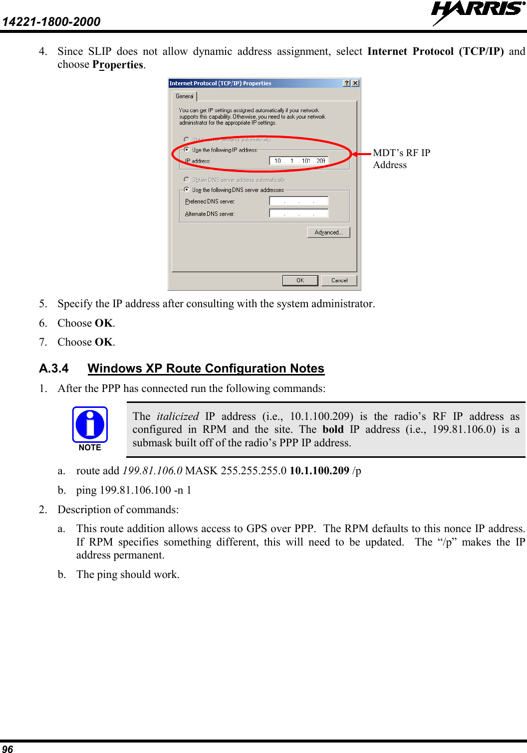
HARRIS
>
TR-0133-E User Manual
>
User Manual
Contents
1.
User Manual
2.
Users Manual
User Manual
Navigation menu
Upload a User Manual
Namespaces
Wiki Guide
HTML
PDF
Info
Views
User Manual
Discussion / Help
Navigation

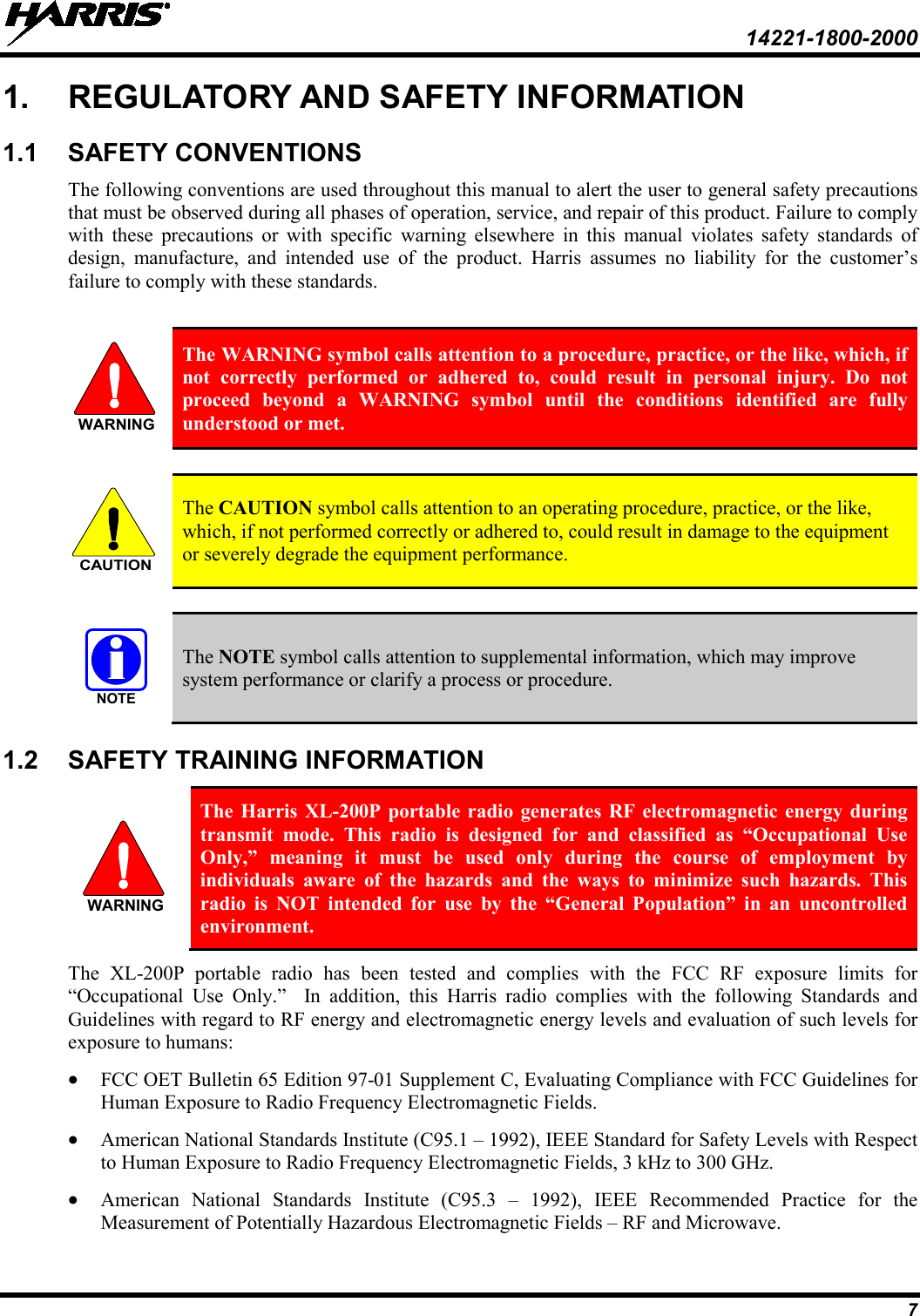
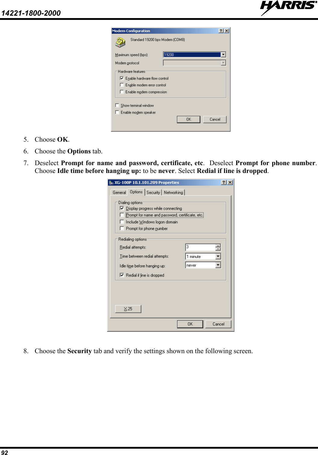
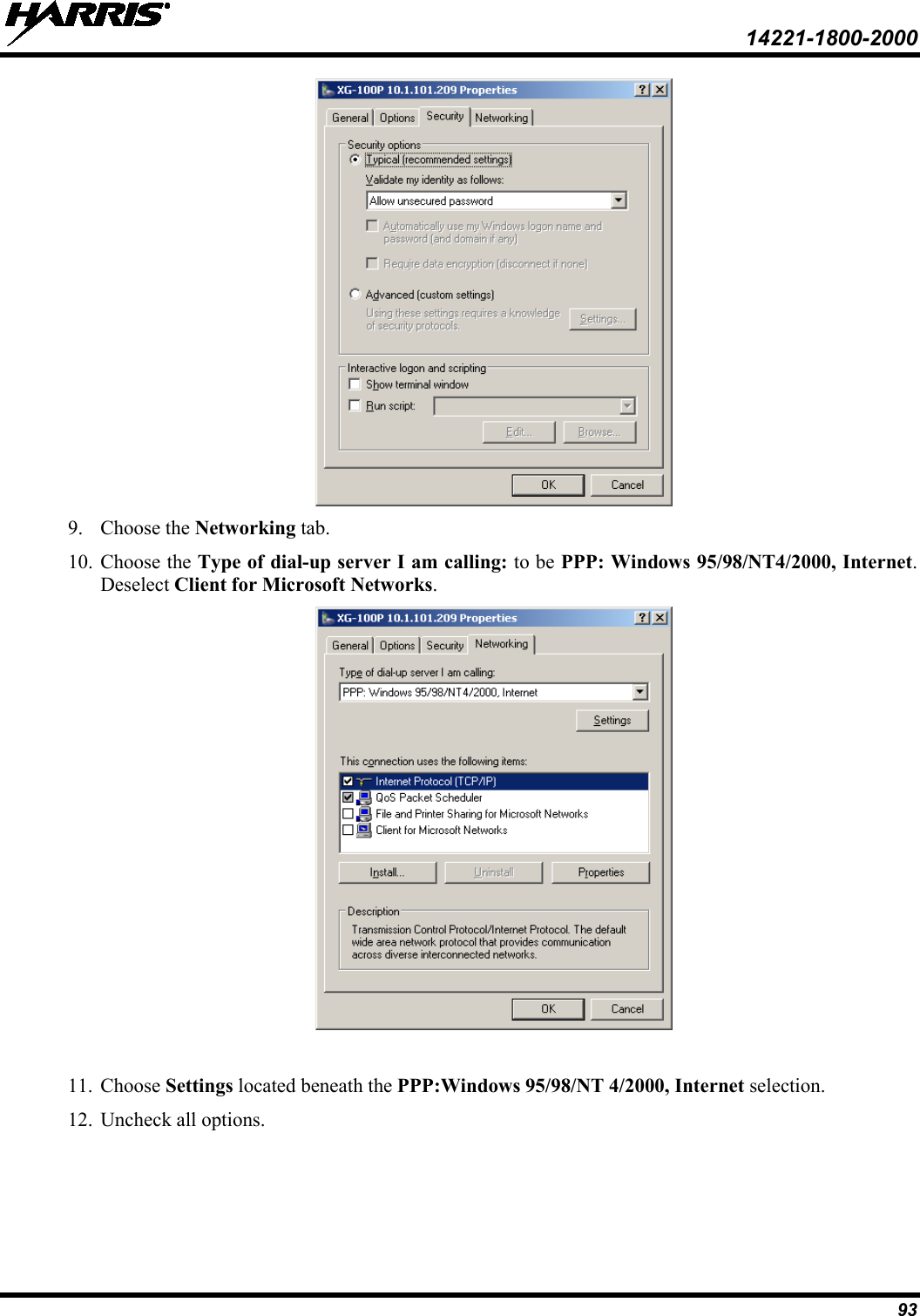
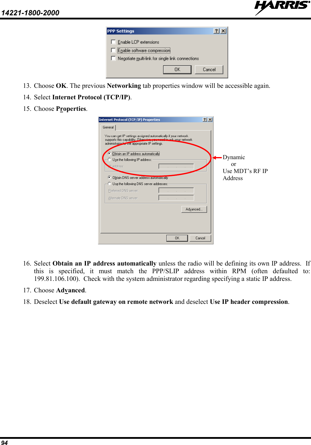
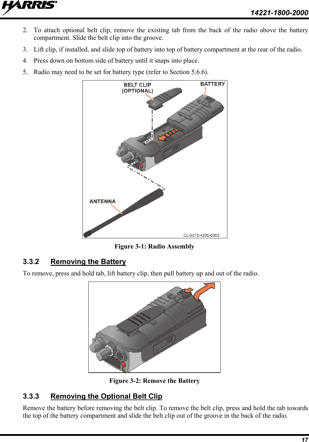
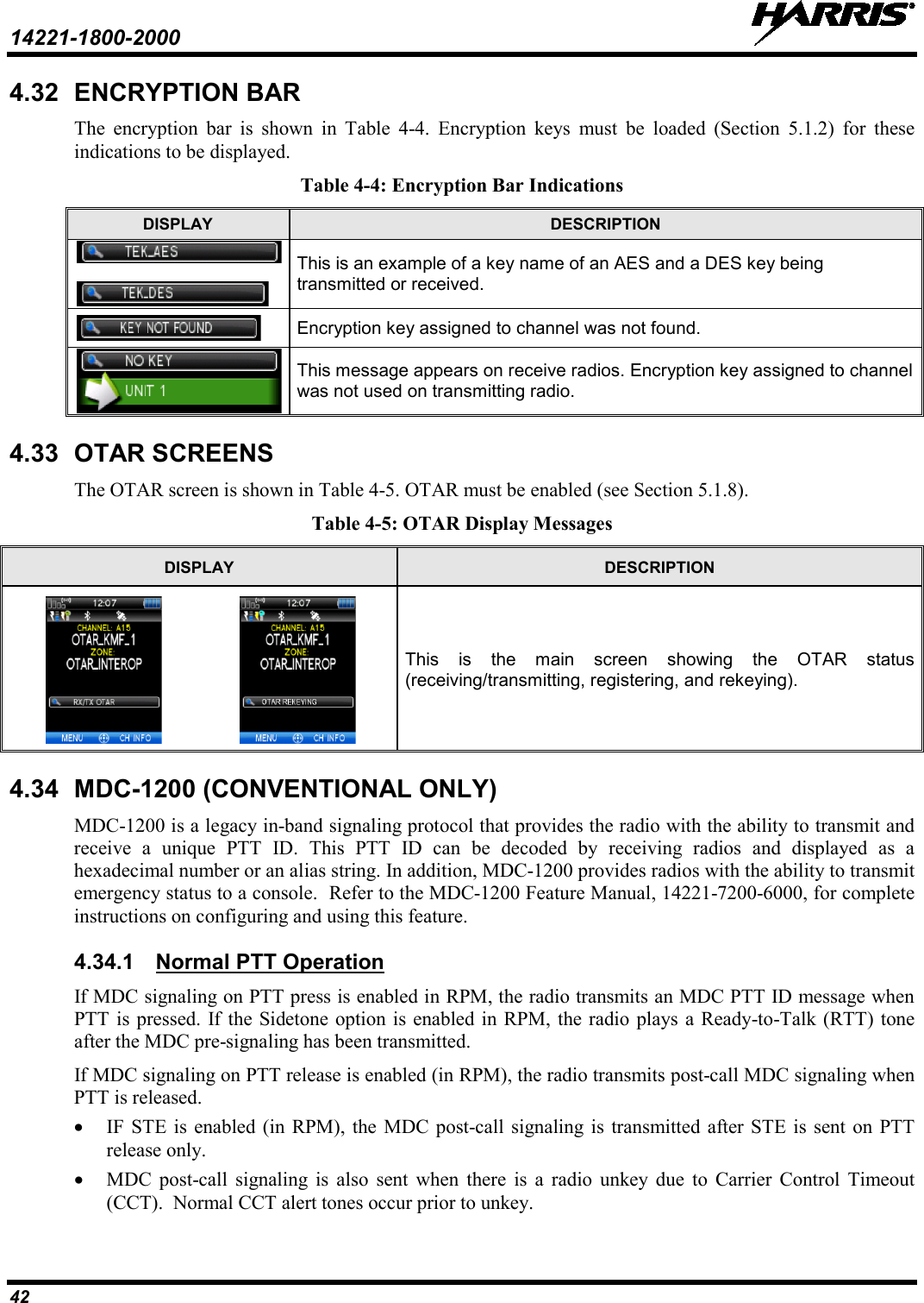
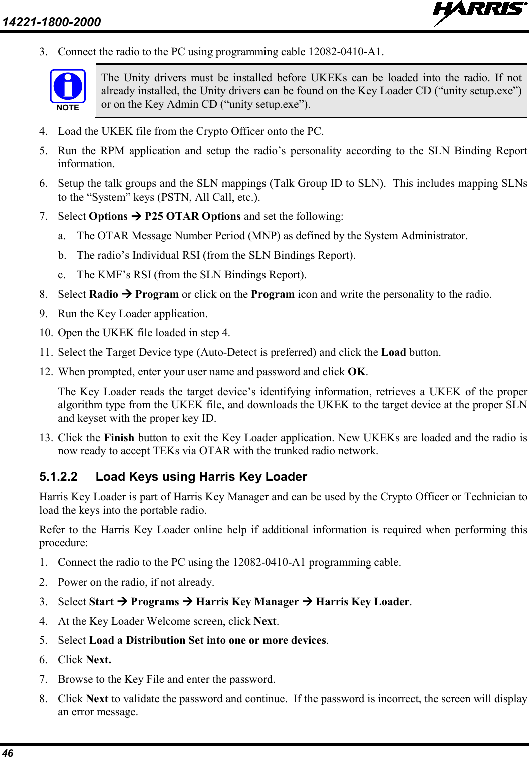
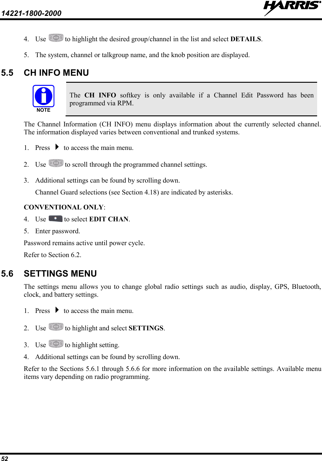
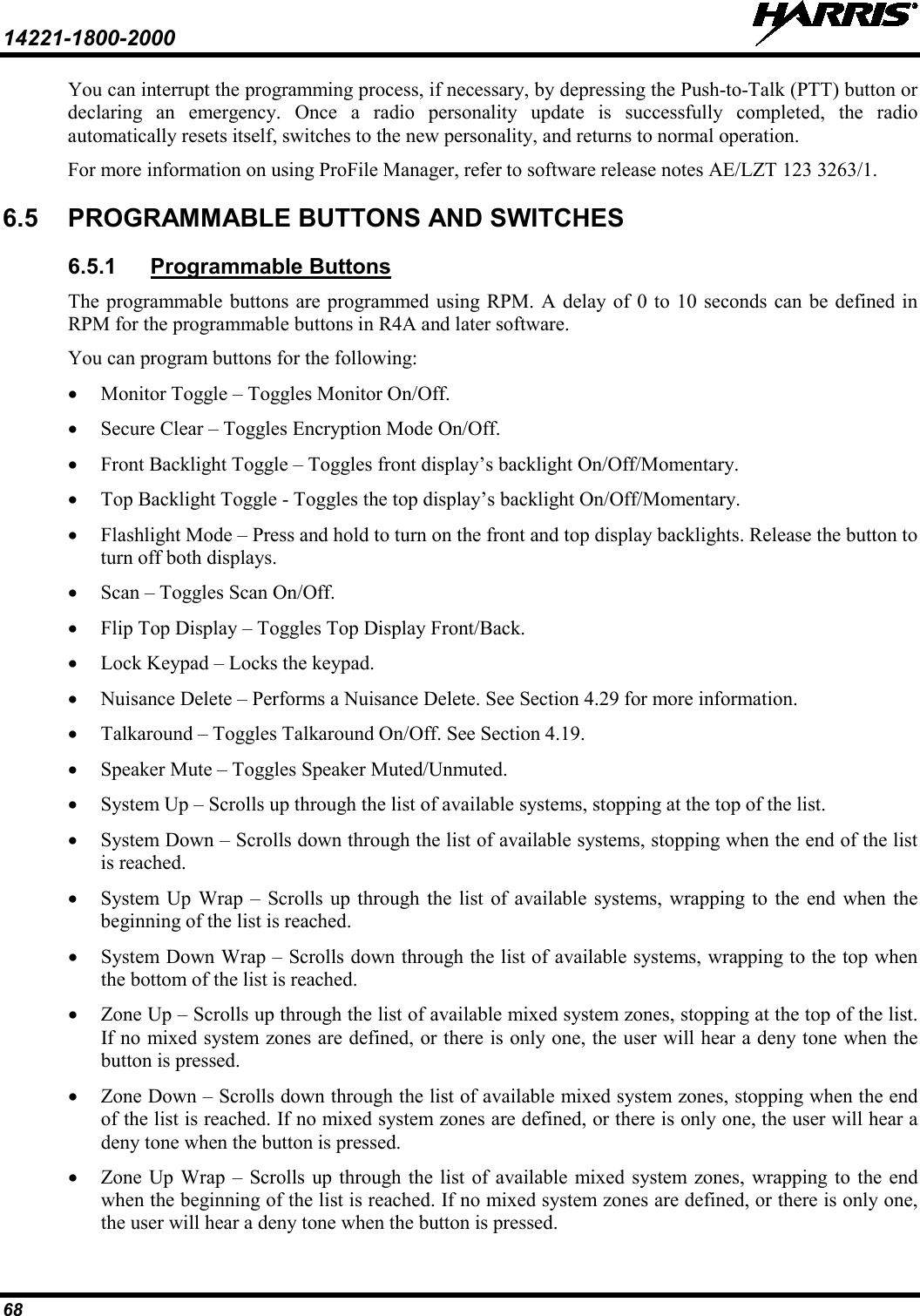
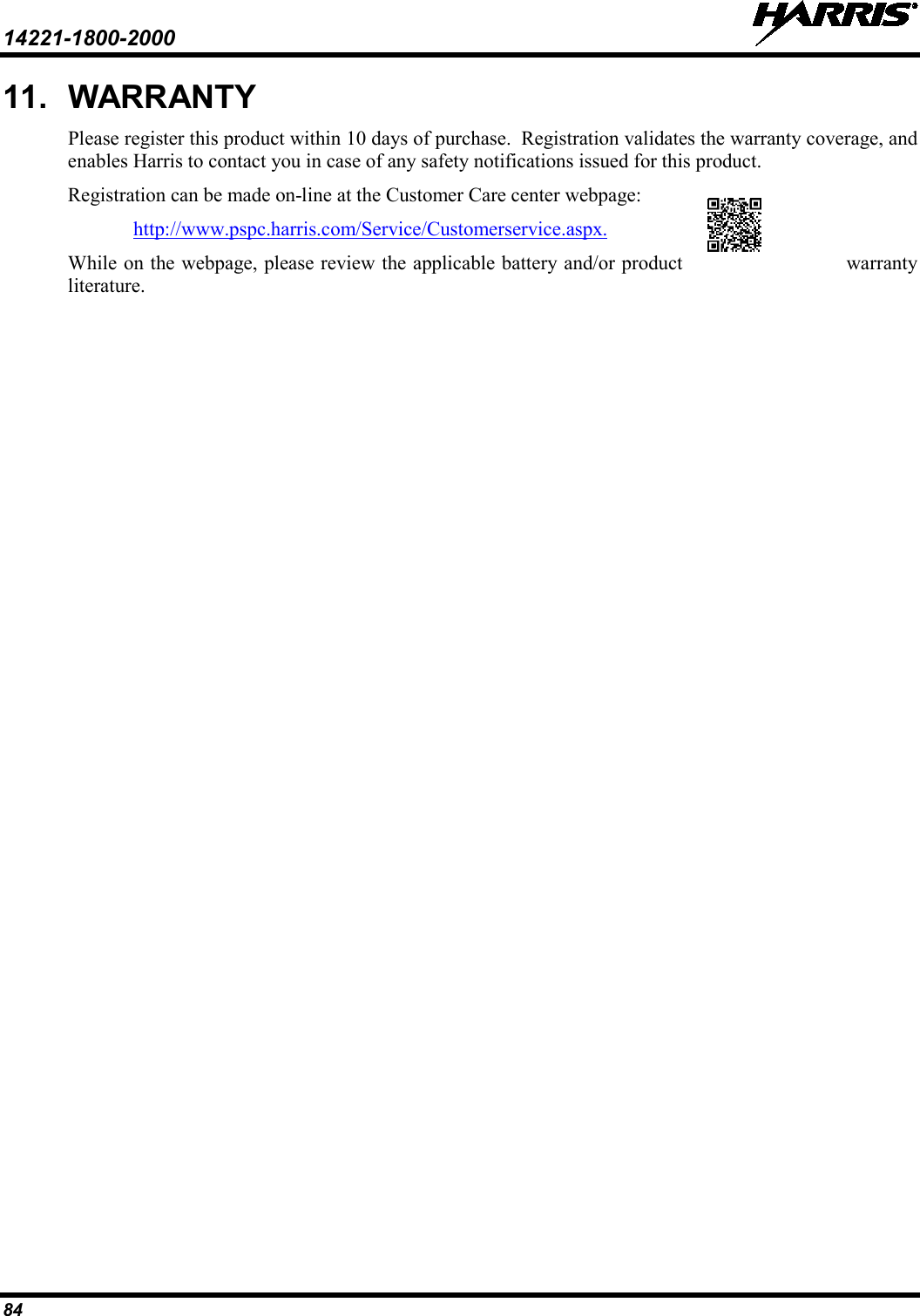
![14221-1800-2000 16 3. INTRODUCTION 3.1 DESCRIPTION The XL-200P provides users with advanced capabilities, interoperability, and ease of use in an extremely rugged radio that performs under the most adverse conditions. By supporting multiple operating modes (P25 Trunked, P25 Conventional, and Analog Conventional) across the VHF, UHF, and 700/800 MHz bands in a single radio, responders can communicate and collaborate with multiple jurisdictions and agencies operating on multiple frequencies and systems. The XL-200P is available with both a Full and Limited keypad and in black and high-visibility yellow. XL-200P features include: • Active Noise Cancellation using three microphones to transmit intelligible audio from users in loud environments • AMBE+2™ Vocoder providing noise cancellation capability and optimizing audio quality for loud and clear communications • Meets MIL-STD-810G for durability and certified for more stringent tests of 1.5-meter drop to concrete • Easy-to-read multi-color front display and monochromatic top display to enhance communications for improved user safety • Instant Recall allowing users to replay the last transmission received • Built-in GPS for position tracking and rapid response for emergencies • Wi-Fi and Bluetooth® functionality For optional accessories, refer to Table 3-1. Additional accessories may have been added since publication of this manual; contact Harris for more information. 3.2 STORAGE GUIDELINES Store your XL-200P and batteries in a clean, cool (not exceeding 86 °F [+30 °C]), dry, and ventilated storage area. 3.3 BASIC SETUP 3.3.1 Assemble the Radio Only use a Harris charger approved for the battery chemistry. Injury could occur from improper charger use. Do not over-tighten the antenna as damage could result. 1. Make sure batteries are charged per charger manual 10515-0372-4010 (supplied with the charger). WARNINGCAUTION](https://usermanual.wiki/HARRIS/TR-0133-E.User-Manual/User-Guide-2553916-Page-17.png)
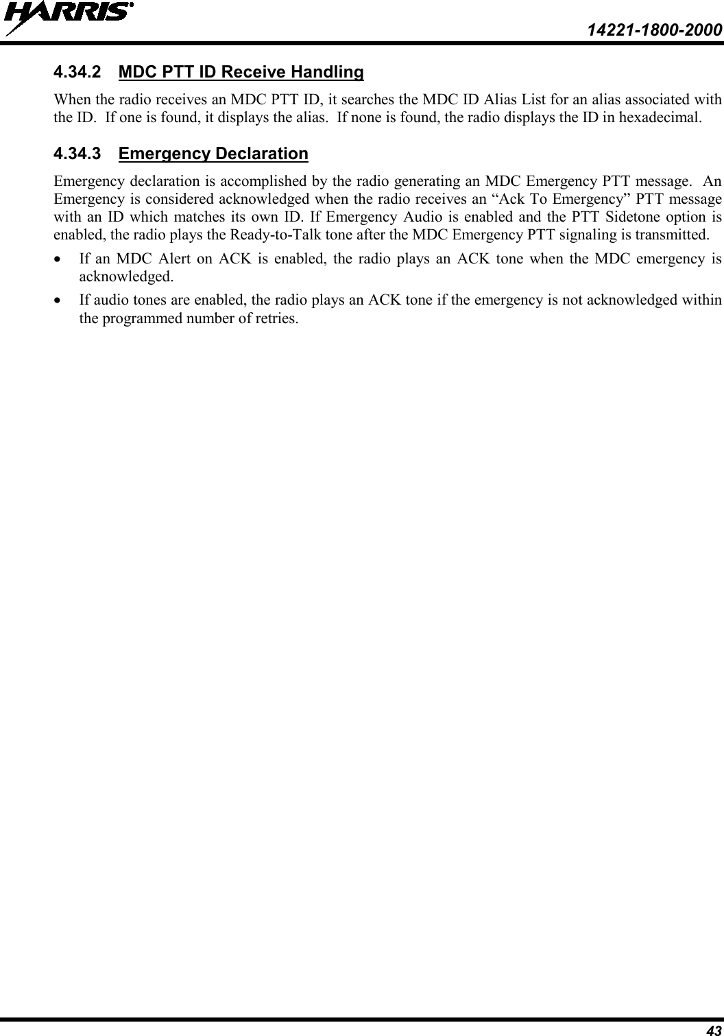
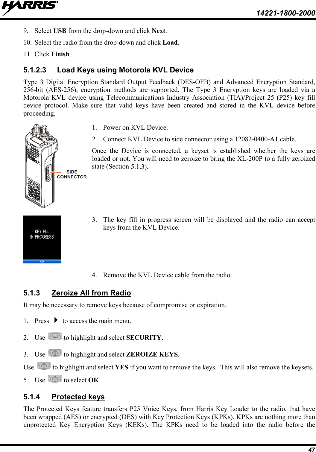
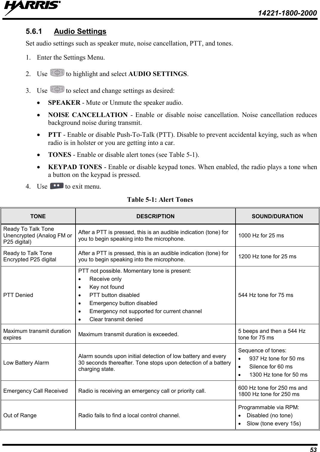
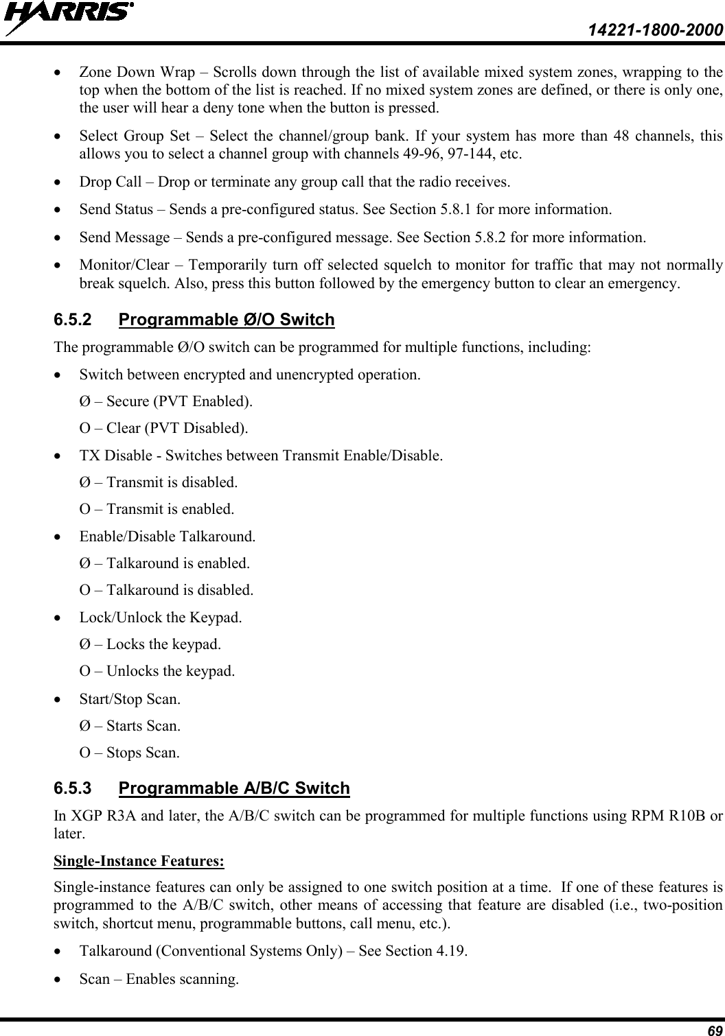
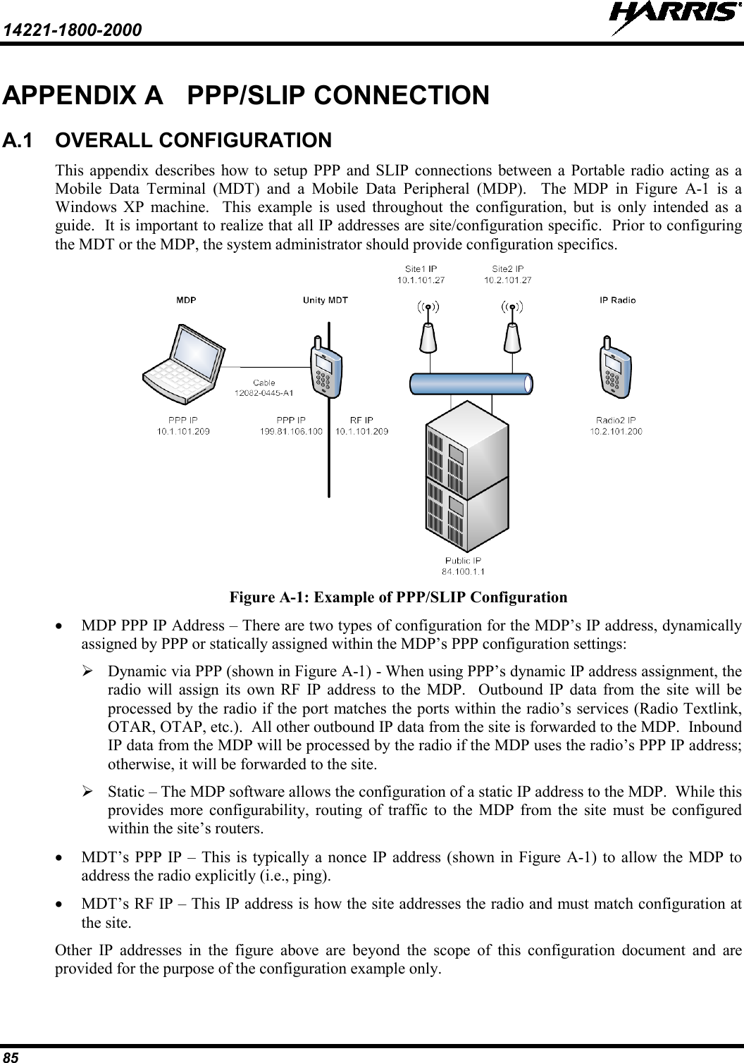
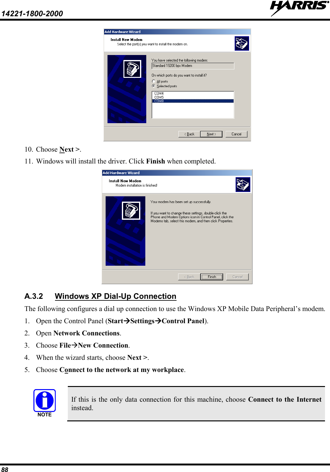
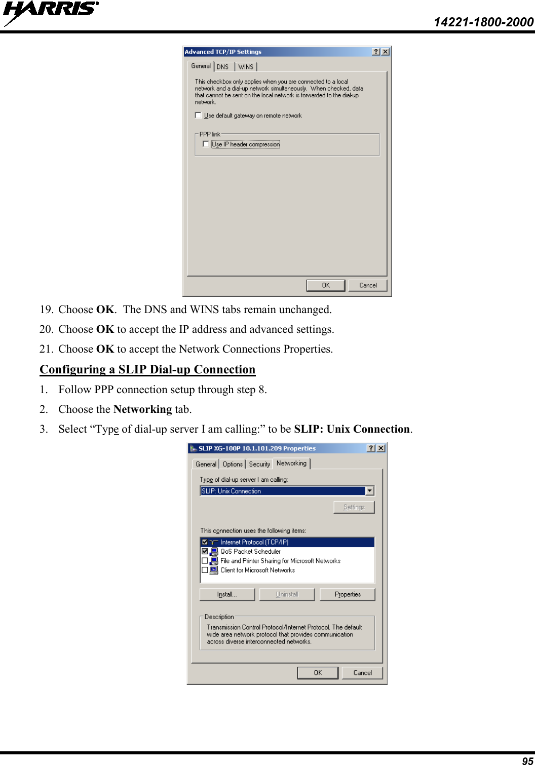
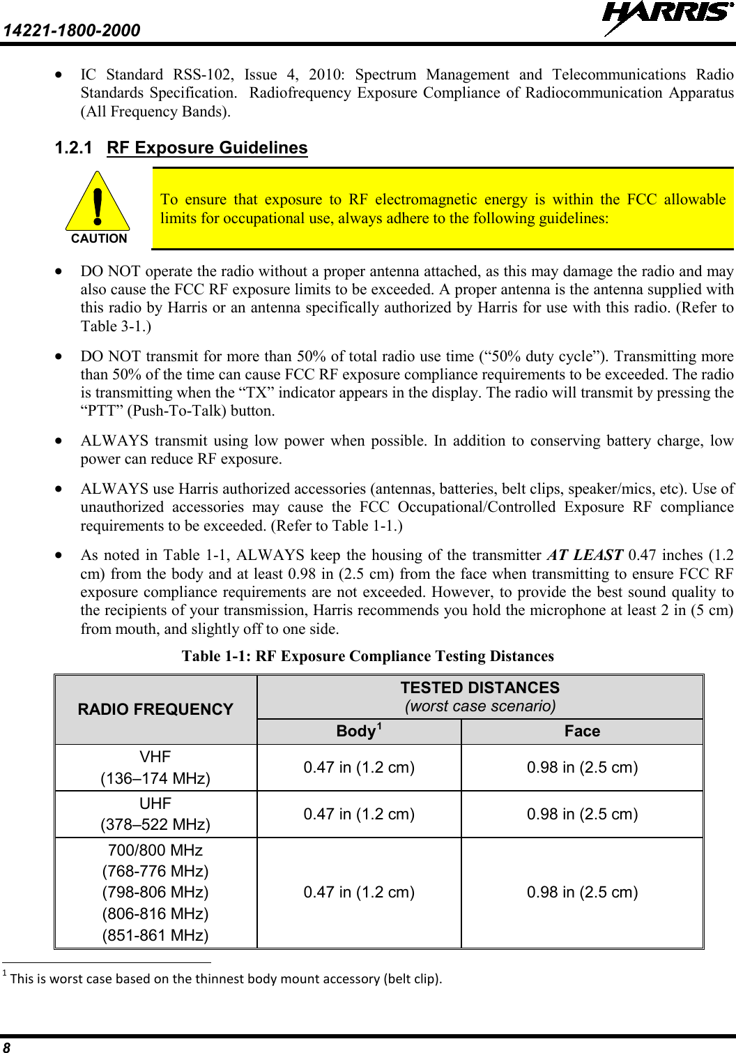
![14221-1800-2000 87 A.3 MDP PPP CONFIGURATION (WINDOWS XP) A.3.1 The following configures a modem that will be used for the PPP connection on a Windows XP Mobile Data Peripheral. Windows XP Modem Configuration 1. Open the Control Panel (StartSettingsControl Panel). 2. Select Phone and Modem Options. 3. Choose Modems tab. 4. Select Add button. 5. Choose “Don’t detect my modem; I will select it from a list.” 6. Choose Next >. 7. Choose the [Standard Modem Types] that corresponds the speed of the radio as configured in the RPM. For a 19200 bps connection, choose Standard 19200 bps Modem. Choosing a modem speed faster than the over-the-air bit rate removes the overhead incurred by PPP layer framing. 8. Choose Next >. 9. Choose the port the radio is connected to.](https://usermanual.wiki/HARRIS/TR-0133-E.User-Manual/User-Guide-2553916-Page-88.png)