Contents
Exihibit 8

Exhibit 8: OEM Interface Manual
©1999 Ericsson Inc. Page 1 of 16
DM-10
OEM INTERFACE MANUAL

Exhibit 8: OEM Interface Manual
©1999 Ericsson Inc. Page 2 of 16
CONTENTS – OEM INTERFACE MANUAL
1. DM10 TRANSCEIVER MODULE OUTLINE DRAWING.......................................................... 3
1.1. MECHANICAL.............................................................................................................................4
1.2. ELECTRICAL ..............................................................................................................................5
1.2.1. ELECTRICAL PERFORMANCE ...............................................................................................5
1.2.2. MOBILE STATION POWER CLASS.........................................................................................6
1.3. POWER CONSUMPTION..............................................................................................................6
1.3.1. TRANSMIT/TALK MODE ......................................................................................................6
1.3.2. STANDBY MODE .................................................................................................................6
1.3.3. SLEEP MODE (MINIMUM DC POWER CONSUMPTION)..........................................................6
2. ABSOLUTE MAXIMUM RATINGS ............................................................................................. 7
3. SAFETY .......................................................................................................................................... 8
3.1. EXPOSURE TO RADIO FREQUENCY ENERGY .............................................................................8
3.2. MODULE OPERATION ................................................................................................................8
3.3. POSTED FACILITIES...................................................................................................................8
3.4. ELECTRONIC DEVICES...............................................................................................................8
3.5. BLASTING AREAS.......................................................................................................................9
3.6. POTENTIALLY EXPLOSIVE ATMOSPHERES ...............................................................................9
3.7. VEHICLES...................................................................................................................................9
3.8. FOR VEHICLES EQUIPPED WITH AN AIRBAG..............................................................................9
3.9. RESPONSIBLE USE .....................................................................................................................9
4. TECHNICAL SPECIFICATIONS ............................................................................................... 12
4.1. GENERAL .................................................................................................................................12
4.2. RECEIVER SECTION.................................................................................................................12
4.3. TRANSMITTER SECTION ..........................................................................................................13
4.4. CONNECTORS...........................................................................................................................13
4.4.1. 30-PIN INTERFACE CONNECTIONS .....................................................................................13
4.4.2. RF INTERFACE CONNECTOR..............................................................................................14
4.4.3. DETAILED SIGNAL DESCRIPTIONS .....................................................................................14
4.4.4. SYSTEM CONNECTOR CMOS INTERFACE LEVELS .............................................................16
4.4.5. ACCESSORY CONNECTOR..................................................................................................16
4.4.6. SYSTEM CONNECTOR .......................................................................................................16
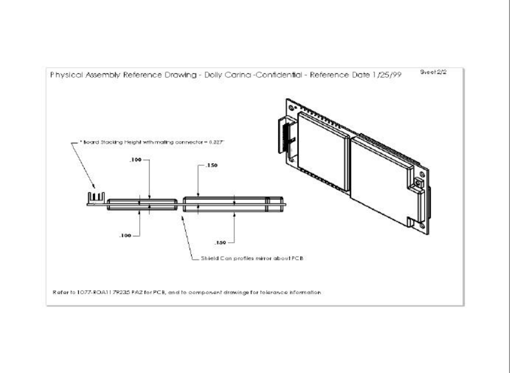
Exhibit 8: OEM Interface Manual
©1999 Ericsson Inc. Page 3 of 16
1. DM10 Transceiver Module Outline Drawing
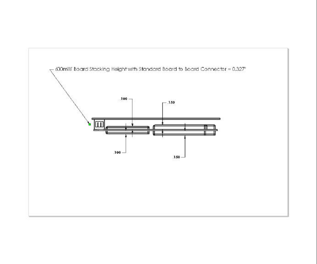
Exhibit 8: OEM Interface Manual
©1999 Ericsson Inc. Page 4 of 16
1.1. Mechanical
The DM-10 module has no mechanical elements other that the main PCB assembly. All critical
electronic components are shielded using sheet metal cans to prevent internal/external
electromagnetic interference from degrading the module’s performance and to prevent the
module from interfering with other nearby devices. The following figure shows a typical
mounting configuration of the module with the main motherboard assembly. The module is
plugged into the fixed mating connector and secured with four screws to the standoff
components.
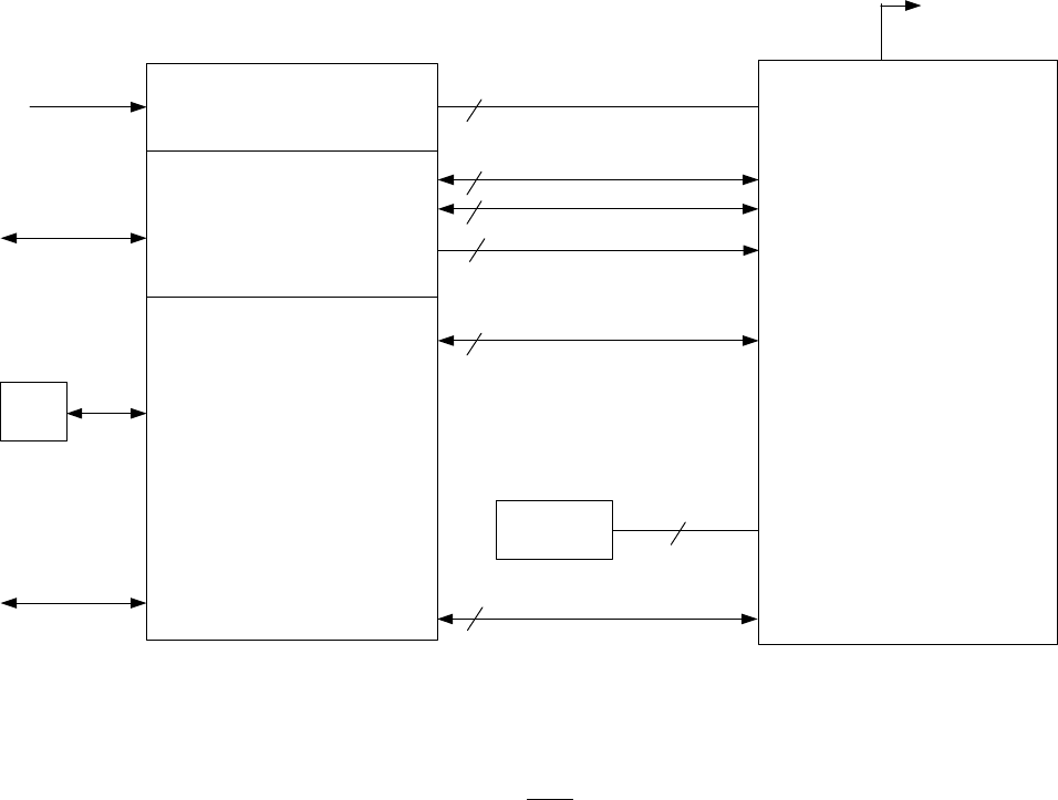
Exhibit 8: OEM Interface Manual
©1999 Ericsson Inc. Page 5 of 16
1.2. Electrical
The diagram below shows an overview of the electrical interface between the DM-10 module
and a typical application.
DM-10 Electrical Interface
Customer Application
HW
Voltage Regulator
Control Processor
Voice & Data Processing
ŸEcho Cancelling
ŸNoise Cancelling
ŸAudio Power AMP
ŸData Conversion
DTE
Power
External Audio
Interface
Antenna
User Interface
6
1
Power & GND
Serial Interface
Wake
Analog Audio Interface
10
1
3
5
4
Clock REF
Option
SIM Device
DM-10
Module
PCM Audio Interface
1.2.1. Electrical Performance
Electrical performance parameters are valid only when the terminating impedance at the
output of the antenna connector exhibits a VSWR of less than 2:1 for all phase angles in
the frequency band of operation. High VSWR loads at the antenna connector adversely
affect current consumption, linearity, and power efficiency of the module and may
prevent operation or cause internal damage.
The RF performance of the DM-10 fully meets the following specifications:
• IS-136 TDMA Cellular mode – Per IS-137 specification
• 553 AMPS Cellular mode – Per IS-19 specification

Exhibit 8: OEM Interface Manual
©1999 Ericsson Inc. Page 6 of 16
• CDPD Mode – Per Cellular Digital Packet Data (CDPD) System Specification, Release
1.1, 19 January 1995 (CDPD will be supported in a future release of the DM10).
1.2.2. Mobile Station Power Class
The module is able to operate in several modes and different output power levels.
Typical applications require output power levels similar to those in a handheld cellular
phone (600-mW nominal) which is considered a power class IV unit for dual mode
operation. It is possible to increase the output power level to that of a class I unit (4 W
nominal) during the 5 second analog burst data mode. The table below shows the
nominal output power levels (Effective Radiated Power, assuming an antenna system
gain of 1 dBd (2.5 dBd antenna gain with 1.5 dB cable loss)).
Mobile Station Nominal Power Levels
Mobile Station Power Level (dBW)
0 1 2 3 4 5 6 7 8 9 10
Class I 6 2 -2 -6 -10 -14 -18 -22 -22 -22 -22
Class IV -2 -2 -2 -6 -10 -14 -18 -22 -27±3-32±4-37±5
*Note: Output power levels maintained within range of +2 / -4 dB unless otherwise
noted
Power levels 8-10 valid for digital mode only
1.3. Power Consumption
1.3.1. Transmit/Talk Mode
DC current in mA AMPS Mode IS-136 Mode CDPD Mode
Peak 617 590 590600 mWatt RMS 617 355 355
3 W Burst Peak 1810 - -
1.3.2. Standby Mode
DC current in mA AMPS Mode IS-136 Mode CDPD Mode
RMS 36 15 15
1.3.3. Sleep Mode (Minimum DC Power consumption)
A power down or "sleep mode" is available in which the module is placed in a low power
consumption state under control of the host application. In this mode, the unit consumes
approximately TBD uA of current as measured from the VCC_6V supply input on pin 1
of the system connector. A logic level "0" on pin 19 of the system connector returns the
unit to full operation although there may be a significant delay while the module
reestablishes registration with the cellular network

Exhibit 8: OEM Interface Manual
©1999 Ericsson Inc. Page 7 of 16
2. Absolute Maximum Ratings
Parameter Rating Units
Supply voltage
6.0 volts 5.2-6.8 Volts
13.6 volts 10.88-16.32 Volts
Operating temperature -40 to +70 °C
Storage temperature -40 to +85 °C
Exhibit 8: OEM Interface Manual
©1999 Ericsson Inc. Page 8 of 16
3. Safety
3.1. Exposure to Radio Frequency Signals
This OEM module is a low power radio transmitter and receiver. The module is not
designed as or to be configured as a hand held device. Use as a portable transmitter will
require separate FCC approval for SAR compliance. Typical usage of this OEM
module includes:
• remote electrical meter reading
• telematic communication for vehicles
• fixed wireless terminals
Warning:
1. At no time is the antenna to be located closer than 20 centimeters to a normally
occupied location.
2. At no time should an antenna system with greater than 1.0 dB gain be used with this
module in any normally occupied area. The recommended antenna system
configuration is a standard automotive antenna with 2.5 dB antenna gain and 1.5 dB
cable loss.
3.2. Module Operation
Safe and efficient use of this module requires a properly terminated antenna. DO NOT
operate the module with a damaged or missing antenna, replace a damaged or missing
antenna immediately otherwise damage to the module may result and could violate
FCC regulations. DO NOT operate this device within 6 inches of a person unless proper
shielding from the antenna is installed.
3.3. Posted Facilities
Do not operate this device where posted notices require wireless devices to be turned
off.
3.4. Electronic Devices
Most electronic equipment is shielded from RF signals. However, certain electronic
equipment may not be shielded properly against RF signals.
Pacemakers
The Health Industries Manufacturers Association recommends that a minimum
separation of six (6) inches be maintained between a wireless transmitter and a
pacemaker to avoid potential interference with the pacemaker. These recommendations
are consistent with the independent research and recommendations of Wireless
Technology Research. Persons with Pacemakers should always keep the
antenna/module more than 6 inches from their pacemaker when the module is on; if
you have a reason to suspect that interference is taking place, turn off the module
immediately.
Exhibit 8: OEM Interface Manual
©1999 Ericsson Inc. Page 9 of 16
Hearing Aids
Some digital wireless devices may interfere with some hearing aids.
Other Medical Devices
If you use any other type of personal medical device in the presence of this transceiver,
consult the manufacturer of your device to determine if it is adequately shielded from
external RF energy. Your physician may be able to assist you in obtaining this
information.
3.5. Blasting Areas
To avoid interfering with blasting operations, turn your module off when in a “blasting
area” or in areas posted: “Turn off two-way radio”. Obey all signs and instructions.
3.6. Potentially Explosive Atmospheres
Turn your module off when in any area with a potentially explosive atmosphere and
obey all signs and instructions. Sparks in such areas could cause an explosion or fire
resulting in bodily injury or even death.
Areas with a potentially explosive atmosphere are often, but not always, clearly
marked. They include such areas as gasoline stations; below deck on boats; fuel or
chemical storage or transfer facilities; vehicles using liquefied petroleum gas (such as
propane or butane); areas where the air contains chemicals or particles, such as grain
dust or metal powders; and any other area where you would normally be advised to turn
off your vehicle engine.
3.7. Vehicles
RF signals may affect improperly installed or inadequately shielded electronic systems
in motor vehicles. Check with the manufacturer or its representative regarding your
vehicle. You should also consult the manufacturer of any equipment that has been
added to your vehicle.
3.8. For Vehicles Equipped with an Airbag
An airbag inflates with a great force. Do not place objects including both installed or
portable wireless equipment in the area over the airbag or in the airbag deployment
area. If in-vehicle wireless equipment is improperly installed and the airbag inflates,
serious injury could result.
3.9. Responsible Use
OEM Manufacturers providing telematic devices for vehicular use are encouraged to
incorporate the following CTIA guidance for safe and responsible wireless phone use
into their user’s manuals:
A Guide to Safe and Responsible Wireless Phone Use
TENS OF MILLIONS OF PEOPLE IN THE U.S. TODAY TAKE ADVANTAGE OF
THE UNIQUE COMBINATION OF CONVENIENCE, SAFETY AND VALUE
Exhibit 8: OEM Interface Manual
©1999 Ericsson Inc. Page 10 of 16
DELIVERED BY THE WIRELESS TELEPHONE. QUITE SIMPLY, THE
WIRELESS PHONE GIVES PEOPLE THE POWERFUL ABILITY TO
COMMUNICATE BY VOICE--ALMOST ANYWHERE, ANYTIME--WITH THE
BOSS, WITH A CLIENT, WITH THE KIDS, WITH EMERGENCY PERSONNEL
OR EVEN WITH THE POLICE. EACH YEAR, AMERICANS MAKE BILLIONS OF
CALLS FROM THEIR WIRELESS PHONES, AND THE NUMBERS ARE
RAPIDLY GROWING.
But an important responsibility accompanies those benefits, one that every wireless
phone user must uphold. When driving a car, driving is your first responsibility. A
wireless phone can be an invaluable tool, but good judgment must be exercised at all
times while driving a motor vehicle--whether on the phone or not.
The basic lessons are ones we all learned as teenagers. Driving requires alertness,
caution and courtesy. It requires a heavy dose of basic common sense---keep your head
up, keep your eyes on the road, check your mirrors frequently and watch out for other
drivers. It requires obeying all traffic signs and signals and staying within the speed
limit. It means using seatbelts and requiring other passengers to do the same.
But with wireless phone use, driving safely means a little more. This brochure is a call
to wireless phone users everywhere to make safety their first priority when behind the
wheel of a car. Wireless telecommunications is keeping us in touch, simplifying our
lives, protecting us in emergencies and providing opportunities to help others in need.
When it comes to the use of wireless phones, safety is your most important call.
Wireless Phone "Safety Tips"
Below are safety tips to follow while driving and using a wireless phone, which should
be easy to remember.
1. Get to know your wireless phone and its features such as speed dial and redial.
Carefully read your instruction manual and learn to take advantage of valuable
features most phones offer, including automatic redial and memory. Also, work to
memorize the phone keypad so you can use the speed dial function without taking
your attention off the road.
2. When available, use a hands free device. A number of hands free wireless phone
accessories are readily available today. Whether you choose an installed mounted
device for your wireless phone or a speaker phone accessory, take advantage of
these devices if available to you.
3. Position your wireless phone within easy reach. Make sure you place your
wireless phone within easy reach and where you can grab it without removing your
eyes from the road. If you get an incoming call at an inconvenient time, if possible,
let your voice mail answer it for you.
4. Suspend conversations during hazardous driving conditions or situations. Let
the person you are speaking with know you are driving; if necessary, suspend the
call in heavy traffic or hazardous weather conditions. Rain, sleet, snow and ice can
Exhibit 8: OEM Interface Manual
©1999 Ericsson Inc. Page 11 of 16
be hazardous, but so is heavy traffic. As a driver, your first responsibility is to pay
attention to the road.
5. Do not take notes or look up phone numbers while driving. If you are reading an
address book or business card, or writing a "to do" list while driving a car, you are
not watching where you are going. It's common sense. Don't get caught in a
dangerous situation because you are reading or writing and not paying attention to
the road or nearby vehicles.
6. Dial sensibly and assess the traffic; if possible, place calls when you are not
moving or before pulling into traffic. Try to plan your calls before you begin your
trip or attempt to coincide your calls with times you may be stopped at a stop sign,
red light or otherwise stationary. But if you need to dial while driving, follow this
simple tip--dial only a few numbers, check the road and your mirrors, then
continue.
7. Do not engage in stressful or emotional conversations that may be distracting.
Stressful or emotional conversations and driving do not mix--they are distracting
and even dangerous when you are behind the wheel of a car. Make people you are
talking with aware you are driving and if necessary, suspend conversations, which
have the potential to divert your attention from the road.
8. Use your wireless phone to call for help. Your wireless phone is one of the greatest
tools you can own to protect yourself and your family in dangerous situations--with
your phone at your side, help is only three numbers away. Dial 9-1-1 or other local
emergency number in the case of fire, traffic accident, road hazard or medical
emergency. Remember that it is a free call on your wireless phone!
9. Use your wireless phone to help others in emergencies. Your wireless phone
provides you a perfect opportunity to be a "Good Samaritan" in your community. If
you see an auto accident, crime in progress or other serious emergency where lives
are in danger, call 9-1-1 or other local emergency number, as you would want
others to do for you.
10. Call roadside assistance or a special wireless non-emergency assistance
number when necessary. Certain situations you encounter while driving may
require attention but are not urgent enough to merit a call for emergency services.
But you still can use your wireless phone to lend a hand. If you see a broken-down
vehicle posing no serious hazard, a broken traffic signal, a minor traffic accident
where no one appears injured or a vehicle you know to be stolen, call roadside
assistance or other special non-emergency wireless number.
Careless, distracted individuals and people driving irresponsibly represent a hazard to
everyone on the road. Since 1984, the Cellular Telecommunications Industry
Association and the wireless industry have conducted educational outreach to inform
wireless phone users of their responsibilities as safe drivers and good citizens. As we
approach a new century, more and more of us will take advantage of the benefits of
wireless telephones. And, as we take to the roads, we all have a responsibility to drive
safely.

Exhibit 8: OEM Interface Manual
©1999 Ericsson Inc. Page 12 of 16
4. Technical Specifications
4.1. General
All ratings @12V supply unless otherwise specified
Parameter Conditions Min Typ Max Unit
Frequency range Transmit 834.390 835.620 MHz
Receive 879.390 880.620 MHz
Channel spacing 30 kHz
Number of channels 42
Supply voltage +8.5 +18 Volts
Supply voltage ripple 10 Hz to 200 kHz 200 mV
Supply current Sleep 1 12 15 mAmps
Standby 225 50 mAmps
Transmit 31300 1800 mAmps
Operating Temperature -40 +60 °C
Antenna port impedance 50 Ohms
ÜÜ Notes
1. In sleep mode neither the receiver nor the transmitter is operating. The communications
interface is completely operational.
2. When receiving a relatively strong signal (>-100 dBm), the typical current is approximately 25
mA. When the signal strength is less than -100 dBm, the operating current is approximately 45
mA.
3. Typical operating current during transmit mode is approximately 1300 mA. The current
required in this mode is sensitive to the quality of the antenna termination impedance. With a
poorly matched antenna, the operating current can approach 2 Amps. Note that a transmission
lasts approximately 118 milliseconds.
4.2. Receiver Section
Parameter Conditions Min Typ Max Units
Sensitivity1-116 dBm
Adjacent channel rejection 16 dB
Alternate channel rejection 60 dB
Intermod rejection 65 dB
RSSI range (digital) -116 -60 dBm
RSSI accuracy (digital) +/- 3 dB
RSSI range (analog) 0.75 1.75 volts
ÜÜ Notes
1 Sensitivity is measured with respect to an analog test point after demodulation of the received
signal. External filtering is applied to make the test consistent with sensitivity tests typically

Exhibit 8: OEM Interface Manual
©1999 Ericsson Inc. Page 13 of 16
performed on cellular telephones (as per IS-19B). The criteria for this test is > 12 dB SINAD for
a 1 kHz audio tone modulating the carrier to 8 kHz peak deviation.
4.3. Transmitter Section
Parameter Min Typ Max Units
Power output1 0.0063 3 Watts (nom)
Transmission duty cycle 2.5 %
Peak Deviation +/- 8 kHz
Frequency Stability - 2.5 + 2.5 ppm
Carrier switching time 2 msec
Channel switching time 40 msec
Power levels (per CMAC) 8 (pwr levels 0-7)
ÜÜ Notes
1 The actual power output is controlled by the AMPS system via the CMAC register in the
overhead control message. Per EIA/TIA-553, the output power varies from +8 dBm to +36
dBm, in 4 dB steps.
4.4. Connectors
4.4.1. 30-pin Interface Connections
Pin Signal Name Description TYPE
1GND Chassis Ground -
2GND/AD_in Chassis Ground (optionally A/D input) -/I
3AFMS Audio from module O
4GND Chassis Ground -
5AGND Analog ground -
6ATMS Audio to module I
7OUT2 * Reserved O
8WAKE Switches the main voltage regulator on/off I
9IN2 * Reserved I
10 OUT1 * Reserved O/I
11 VDD * Logic reference O
12 IN1 * Reserved I
13 PCMCLK PCM Clock output O
14 PCMSYNC PCM Frame sync O
15 PCMULD PCM Voice input I
16 PCMDLD PCM Voice output O
17 GND Chassis Ground -
18 GND Chassis Ground -
19 DCD/VppFlash Data Carrier Detect and Flash Programming Voltage Input O/I
20 REF_CLK 19.44 MHz reference clock output O
Exhibit 8: OEM Interface Manual
©1999 Ericsson Inc. Page 14 of 16
Pin Signal Name Description TYPE
21 CTS Clear to send O
22 DTR Data Terminal Ready I
23 TD Serial data to module I
24 RTS Request to Send I
25 VCC_12V 12 vdc supply (needed only for 3 Watt burst applications) I
26 RD Serial data from module O
27 VCC_12V 12 vdc supply (needed only for 3 Watt burst applications) I
28 VCC_12V 12 vdc supply (needed only for 3 Watt burst applications) I
29 VCC_6V 6 vdc regulated supply voltage I
30 VCC_6V 6 vdc regulated supply voltage I
* Pin used for SIM Interface in GSM based products. Pin function reserved for future use by
U.S. products.
ÜÜ Notes
In modem mode, pin 8 is configured as an output and indicates whether a message is stored in
the output buffer. In standalone mode, pin 8 is configured as an input and is used to warn the
transceiver of an impending power failure.
4.4.2. RF Interface Connector
Radio frequency (RF) signals from the module to the external, customer-supplied antenna are
made through a surface mount, microminiature snap-on M/A-COM connector. A wide variety of
compatible mating connectors is available. A Pigtail assembly and the inter-series cable
assembly from M/A-COM are two options. Since the mating connector can rotate through 360o,
the application developer has maximum flexibility for routing the RF coax assembly. The total
height of the mated M/A-COM RF connectors is 0.12 inches.
4.4.3. Detailed Signal Descriptions
DGND This is the supply voltage return (VCC_6V and VCC_12V)
Minimum Maximum
Input voltage for 0000 0000 word 0.05V
Input voltage for 1111 1111 word 3.25V
Linearity ± 0.5 LSB
Absolute accuracy -10mV +10mV
Conversion time to within 0.5 bit 5µ sec
Input impedance 1MΩ
A/D_in
External source impedance

Exhibit 8: OEM Interface Manual
©1999 Ericsson Inc. Page 15 of 16
Module audio output
Output Impedance (active state)
Output Impedance (inactive state)
Output Impedance (pwr down state)
Drive capacity into 50 Ω
Drive capacity into 5 kΩ
(0.3 – 3.5 kHz)
Zout < 10 Ω in series with ≥3.3
uF (-20%)
Zout < 10 Ω to VDD/2
Zout > 30 kΩ
1.1 VP-P min.
2.0 VP-P min./ 4.0 VP-P max.
External Device audio input Input
Impedance Zin > 50 Ω
Volume control ± 12 dB from nominal > - 40
dB (mute)
AFMS
Levels to external audio input 28 mVrms nominal 450
mVrms max.
All sources must be AC coupled except for a microphone device. External
audio source should be DC coupled in order for module to supply DC power
to microphone.
External audio source
Output impedance (active state)
Output impedance (inactive state) Zout ≤ 100 Ω
Zout > 10 k
Module audio input
Input impedance
Output DC level unloaded for external
audio source power
Zin > 2 kΩ
2.0 V min.
Levels from external audio source HGA
= 0 45 mVrms nominal 340 mVrms
max.
ATMS
Audio input signal is amplified an
additional 32 db and a DC bias is
provided to the microphone when HGA
= 1
1.5 mVrms nominal
OUT1, OUT2 CMOS open drain output with 1 mA drive (See Section 4.3.4)
WAKE TTL compatible active low input (WAKE pin is tied to VDD through 51kΩ
resistor, recommend open collector/drain transistor)
I_01, I_03 CMOS bi-directional, tri-state output with 2mA drive (See Section 4.3.4)
VDD 2.7 Vdc min 3.4 Vdc nominal 5.5 Vdc max
PCMCLK (See Section 4.3.4)
PCMSYNC (See Section 4.3.4)
PCMULD (See Section 4.3.4)
PCMDLD (See Section 4.3.4)
(See Section 4.3.4)DCD/VppFlash VppFlash programming voltage. Capability =
60 ma min 11.8 – 12.2 Vdc
Frequency 19.44 MHz this output is switchable
Output Level 0.7 min 1.0 typ 1.4 max volts-P2P
REF_CLK
Harmonic Content -10dBc max
RTS, CTS, DTR (See Section 4.3.4)

Exhibit 8: OEM Interface Manual
©1999 Ericsson Inc. Page 16 of 16
RD,TD (See Section 4.3.4)
VCC_12V 13.6 volt ± 20%, 1.5 A max
VCC_6V 6 volt ± 13.3% regulated, 1A max
4.4.4. System Connector CMOS Interface Levels
LimitsQuantity Symbol Min Typ Max Units
High level output voltage (IOH= rated) VOH 0.9 *VDD VDD Volts
Low level output voltage (IOL= rated) VOL 00.1.*VDD Volts
High level input voltage VIH 0.8 *VDD VDD Volts
Low level input voltage VIL 00.2 *VDD Volts
4.4.5. Accessory Connector
Connections to an optional accessory board are made through a 14-pin accessory connector. Add-on
accessories under consideration include a GPS receiver, a Bluetooth transceiver, and a CeBus transceiver
16-Pin Accessory Connector Functions
Connector / Pin Signal Name Description
X353 / 1 VCC_6V 6 VDC supply input
X353 / 2 GND Digital ground
X353 / 3 CLKREQ Request from accessory to keep providing reference clock
X353 / 4 ARESET Reset signal to accessory
X351 / 1 ASYNC Request from accessory for frame sync
X351 / 2 TBD SPARE
X351 / 3 IU3T DTMS
X351 / 4 IU3R DFMS
X351 / 5 ADATAUP Data to accessory (PCM link)
X351 / 6 APCMSYNC Sync line (PCM link)
X351 / 7 APCMCLK Clock line (PCM link)
X351 / 8 ADATDOWN Data from accessory board (PCM link)
X351 / 9 ASYSCLK 19.44 MHz reference clock to accessory
X351 / 10 AWAKE Wake-up signal to accessory
X351 / 11 IU2T IU2T
X351 / 12 IU2R IU2R
4.4.6. System Connector
External interfaces to the module are made primarily through a 30-pin, standard 0.050 inch pitch,
ODU header shown.