HARRIS TR-0049-E M5300 900 MHz Mobile Radio User Manual MM 014714 001rP3
HARRIS CORPORATION M5300 900 MHz Mobile Radio MM 014714 001rP3
HARRIS >
Contents
Manual 2
Installation Manual
MM-014714-001
Apr/08
M/A-COM
CS-7000 Control Station
MM-014714-001, Rev. P3
2
MANUAL REVISION HISTORY
REV. DATE REASON FOR CHANGE
– Apr/08 Original release.
M/A-COM Technical Publications would particularly appreciate feedback on any errors found in this document and
suggestions on how the document could be improved. Submit your comments and suggestions to:
Tyco Electronics Wireless Systems Segment
M/A-COM, Inc. or fax your comments to: 1-434-455-6851
Technical Publications
221 Jefferson Ridge Parkway or e-mail us at: techpubs@tycoelectronics.com
Lynchburg, VA 24501 CREDITS
M/A-COM, Inc. and/or Tyco Electronics may have patents, patent applications, trademarks, copyrights, or other intellectual
property rights covering subject matter in this document. Except as expressly provided in any written license agreement from
M/A-COM, the furnishing of this document does not give you any license to these patents, trademarks, copyrights, or other
intellectual property.
The software contained in this device is copyrighted by M/A-COM, Inc. Unpublished rights are reserved under the copyright
laws of the United States.
This device made under license under one or more of the following U.S. Patents: 4,590,473; 4,636,791; 5,148,482;
5,185,796; 5,271,017; 5,377,229; 4,716,407; 4,972,460; 5,502,767; 5,146,497; 5,164,986; 5,185,795
The voice coding technology embodied in this product is protected by intellectual property rights including patent rights,
copyrights, and trade secrets of Digital Voice Systems, Inc. The user of this technology is explicitly prohibited from
attempting to decompile, reverse engineer, or disassemble the Object Code, or in any other way convert the Object Code into
human-readable form.
OpenSky® and EDACS® are registered trademarks of M/A-COM, Inc.
Bird is a registered trademark of Bird Electronic Corporation. Microsoft® and Windows® are registered trademarks of
Microsoft Corporation.
NOTICE!
This manual covers M/A-COM products manufactured and sold by M/A-COM, Inc.
Repairs to this equipment should be made only by an authorized service technician or facility designated by the supplier. Any
repairs, alterations or substitution of recommended parts made by the user to this equipment not approved by the
manufacturer could void the user’s authority to operate the equipment in addition to the manufacturer’s warranty.
M/A-COM recommends the buyer use only M/A-COM authorized representatives to install and service this product. The
warranties provided to buyer under the terms of sale shall be null and void if this product is installed or serviced improperly
and M/A-COM shall have no further obligation to the buyer for any damage caused to the product or to any person or
personal property.
This product conforms to the European Union WEEE Directive 2002/96/EC. Do not dispose of this product in a
public landfill. Take it to a recycling center at the end of its life.
This manual is published by M/A-COM, Inc. without any warranty. Improvements and changes to this manual necessitated
by typographical errors, inaccuracies of current information, or improvements to programs and/or equipment, may be made
by M/A-COM, Inc., at any time and without notice. Such changes will be incorporated into new editions of this manual. No
part of this manual may be reproduced or transmitted in any form or by any means, electronic or mechanical, including
photocopying and recording, for any purpose, without the express written permission of M/A-COM, Inc.
Copyright© 2008, M/A-COM, Inc. All rights reserved.

MM-014714-001, Rev. P3
3
TABLE OF CONTENTS
Section Page
1 REGULATORY AND SAFETY INFORMATION ...................................................................................6
1.1 MAXIMUM PERMISSIBLE EXPOSURE LIMITS..............................................................................6
1.1.1 Determining MPE Radius ...........................................................................................................6
1.1.2 Safety Training Information........................................................................................................6
1.2 SAFETY SYMBOL CONVENTIONS...................................................................................................7
1.3 IMPORTANT SAFETY INSTRUCTIONS............................................................................................8
2 SPECIFICATIONS.......................................................................................................................................9
3 INTRODUCTION.......................................................................................................................................12
3.1 VOICE OPERATION...........................................................................................................................13
3.2 OPTIONAL REMOTE CONTROL BOARD.......................................................................................13
3.2.1 Intercom Operation ...................................................................................................................13
3.3 RELATED DOCUMENTATION ........................................................................................................13
3.4 TECHNICAL ASSISTANCE...............................................................................................................14
3.5 CUSTOMER RESOURCE CENTER...................................................................................................14
4 UNPACKING AND CHECKING EQUIPMENT....................................................................................15
4.1 MATERIALS .......................................................................................................................................15
4.2 MATERIAL INSPECTION .................................................................................................................15
5 INSTALLATION........................................................................................................................................17
5.1 REQUIRED TOOLS AND EQUIPMENT...........................................................................................17
5.1.1 Tools and Shop Supplies Required to Install the CS-7000 .......................................................17
5.1.2 Equipment Required for CS-7000 Configuration......................................................................17
5.2 PLANNING THE CS-7000 INSTALLATION.....................................................................................17
5.3 CS-7000 INSTALLATION ..................................................................................................................18
5.3.1 Desktop Installations.................................................................................................................18
5.3.2 Rack-Mount Installation............................................................................................................18
5.3.3 AC Power Connection...............................................................................................................19
5.3.4 AC Fuse Replacement...............................................................................................................19
5.4 ANTENNA INSTALLATION.............................................................................................................20
5.4.1 RF Safety Information...............................................................................................................20
5.4.2 General Information..................................................................................................................20
5.4.3 Building Installation Considerations.........................................................................................21
5.4.4 Base Station Antennas...............................................................................................................21
5.4.5 Transmission Lines ...................................................................................................................21
5.4.5.1 Minimum Transmission Line Bending Radius........................................................................ 21
5.4.6 Tower Installations....................................................................................................................22
5.5 GROUNDING AND LIGHTNING PROTECTION ............................................................................22
5.6 BACKUP POWER SOURCES.............................................................................................................23
5.6.1 Uninterruptible Power Supplies ................................................................................................23
5.6.2 Gas/Propane Generators............................................................................................................23
5.6.3 Hydrogen Power Systems .........................................................................................................23
5.7 CONNECTING VOIP DESKTOP REMOTE CONTROLLERS..........................................................23
5.7.1 Setting Up the LAN Port for VoIP Connectivity ......................................................................23
5.7.2 Setting Up VoIP Desktop Remotes...........................................................................................23
5.8 CONNECTING TONE REMOTE CONTROLLERS ..........................................................................24
5.8.1 Standard Tone Signaling...........................................................................................................24
5.8.2 Dual Function Tone Signaling ..................................................................................................24
5.8.3 Connecting One Tone Remote Controller.................................................................................26
5.8.4 Connecting More-than-One Tone Remote Controllers .............................................................26
5.8.4.1 LINE Input Connector............................................................................................................. 27
5.9 CONNECTING CAN –LINKED REMOTE CONTROLLERS...........................................................27
5.9.1 General Information..................................................................................................................27

MM-014714-001, Rev. P3
4
TABLE OF CONTENTS
Section Page
5.9.2 CAN-Linked Desktop Controller Connections .........................................................................29
5.9.2.1 Collocated Installations............................................................................................................30
5.9.2.2 In-Wall/Plenum CAN Cable Installations ................................................................................30
5.9.2.2.1 Cable Requirements and Routing........................................................................................................30
5.9.2.2.2 Installation Materials ..........................................................................................................................31
5.9.2.2.3 Splicing CAN Cables..........................................................................................................................31
5.9.3 Connecting a CAN Bus Extender (Fiber Optic Cable Installations) .........................................33
5.10 CONNECTING DEVICES TO THE EXTERNAL I/O ........................................................................33
5.10.1 Local and Remote Speaker – Jumper Configuration.................................................................33
5.10.2 External I/O Connector (P3) Pinout ..........................................................................................33
6 INITIAL SETUP .........................................................................................................................................36
6.1 CONTROL STATION POWER-UP PROCEDURE ............................................................................36
6.2 LOCAL CONTROL STATION SETUP AND ALIGNMENT.............................................................36
6.3 VOIP (LAN) SETUP AND ALIGNMENT ...................................................................................................36
6.3.1 Programming the VoIP Remote Board......................................................................................37
6.3.1.1 Programming Parameters .........................................................................................................37
6.3.1.2 Network....................................................................................................................................37
6.3.1.3 Radio........................................................................................................................................37
6.3.1.4 Output.......................................................................................................................................38
6.3.1.5 Action.......................................................................................................................................38
6.3.1.6 Channel ....................................................................................................................................39
6.3.1.7 Remote Configuration..............................................................................................................39
6.3.2 Audio Adjustments....................................................................................................................43
6.3.2.1 Audio........................................................................................................................................43
6.3.2.2 Backup .....................................................................................................................................43
6.4 TONE REMOTE (LINE I/O) SETUP AND ALIGNMENT .................................................................44
7 OPERATIONAL TESTING.......................................................................................................................45
7.1 SETUP AND EQUIPMENT TESTING................................................................................................45
7.1.1 REQUIRED TEST EQUIPMENT ............................................................................................45
7.2 MAXIMUM EFFECTIVE RADIATED POWER ................................................................................46
7.2.1 Determining Maximum Transmitter Power that Meets ERP Requirement ...............................46
7.2.1.1 For OpenSky Mode of Operation.............................................................................................46
7.2.1.2 For P25, EDACS, or Conventional Mode of Operation...........................................................47
7.3 VERIFYING TX RF FORWARD AND REFLECTED POWER.........................................................47
7.4 VERIFYING TX RF FREQUENCY.....................................................................................................48
7.5 VERIFYING TX MODULATION.......................................................................................................49
7.5.1 Digital Modulation Modes (EDACS, P25, and OpenSky)........................................................49
7.5.2 Analog Modulation Modes........................................................................................................49
7.5.2.1 Desktop Remote Controllers on Systems Using Analog Modes ..............................................50
8 COMPLETING THE INSTALLATION ..................................................................................................51
8.1 FINAL OVER-THE-AIR TESTING ....................................................................................................51
APPENDIX A CONFIGURING VOIP REMOTE CONTROLLERS.................................................. A-1
A.1 IDA MODEL 24-66 VOIP REMOTE CONTROLLER SETUP....................................................... A-3
APPENDIX B INSTALLATION CHECKLIST.................................................................................. B-1
B.1 INSTALLATION DATA SHEET FOR CS-7000 CONTROL STATION ........................................B-3

MM-014714-001, Rev. P3
5
TABLE OF CONTENTS
Section Page
FIGURES
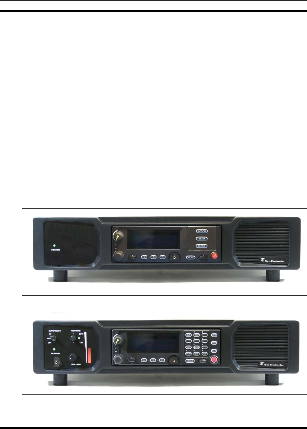
Figure 3-1: CT-013892-001 Local Control Station with Scan Head (Front View).............................12
Figure 3-2: CT-013892-002 Local/Remote Control Station with System Head (Front View) ...........12
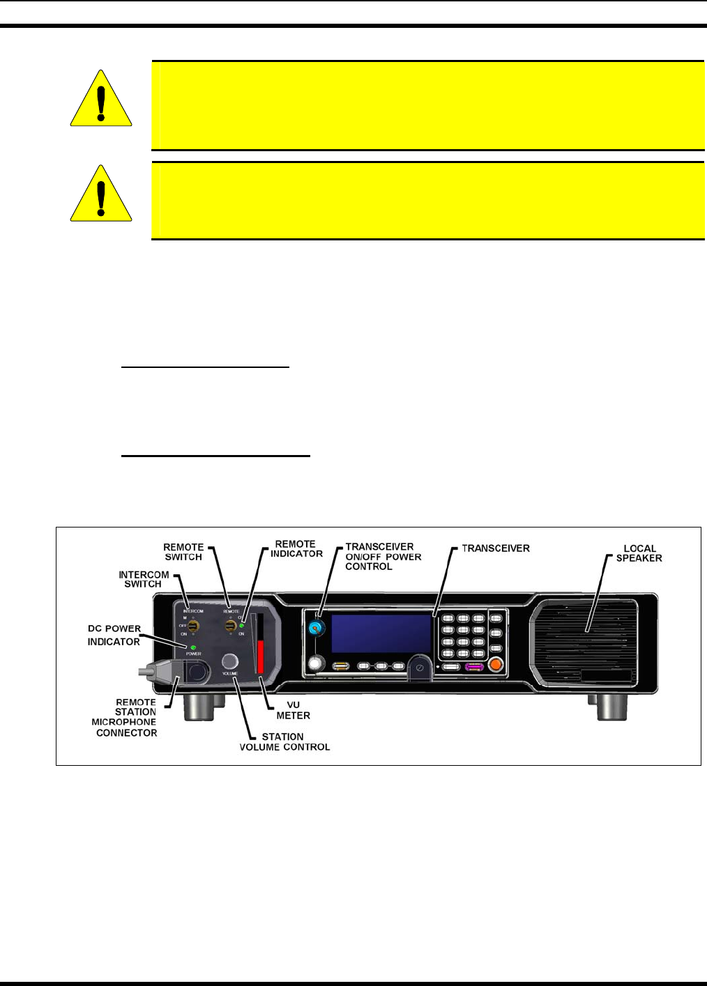
Figure 5-1: CS-7000 with Remote Control, Front View.....................................................................18
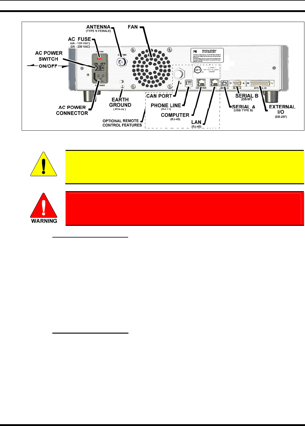
Figure 5-2: CS-7000 Rear Panel (shown with Remote Control Board installed)................................19
Figure 5-3: CS-7000 Fuse Replacement (Rear Panel Views) .............................................................20
Figure 5-4: Tone Remote Control Signaling.......................................................................................25
Figure 5-5: Line Input Configured as an Endpoint and Interfaced to One TRC .................................26
Figure 5-6: Configured as an Endpoint and Interfaced to Multiple Paralleled TRCs .........................26
Figure 5-7: Control Station in the Middle of a Chain and Interfaced to Multiple Paralleled TRCs....27
Figure 5-8: Connecting a CAN-linked Desktop Controller.................................................................28
Figure 5-9: Connecting Two or More CAN-Linked Desktop Controllers ..........................................29
Figure 5-10: Connecting a CAN Y-Cable at the Control Station........................................................29
Figure 5-11: Connecting In-Wall/Plenum CAN Cable Connections ..................................................31
Figure 5-12: Dimensions for Stripping 2-Wire (with Shield) CAN Cables ........................................32
Figure 5-13: 3-Position Terminal Strip Connections ..........................................................................32
TABLES
Table 3-1: Reference Documents........................................................................................................13
Table 4-1: Catalog, Description, and Part Numbers for the CS-7000 Control Station........................15
Table 4-2: Accessories for the CS-7000 Control Station ....................................................................16
Table 5-1: Minimum Bend Radius Values for RF Transmission Lines..............................................22
Table 5-2: Typical* Tone Functionality for Tone Remote Control Signaling....................................25
Table 5-3: LINE Input Pin-Out (RJ-11 Modular Jack Labeled “LINE”) ............................................27
Table 5-4: Interface Board Jumper Configurations..............................................................................33
Table 5-5: Local Control Station - External I/O Port (P3) Wiring Interconnections ..........................34
Table 5-6: Remote Control Station - External I/O Port (P3) Wiring Interconnections.......................35
Table 7-1: Required Test Equipment...................................................................................................45
MM-014714-001, Rev. P2
6
1 REGULATORY AND SAFETY INFORMATION
1.1 MAXIMUM PERMISSIBLE EXPOSURE LIMITS
DO NOT TRANSMIT with this Control Station and antenna when persons are within the MAXIMUM
PERMISSIBLE EXPOSURE (MPE) Radius of the antenna. The MPE Radius is the minimum distance
from the antenna axis that ALL persons should maintain in order to avoid RF exposure higher than the
allowable MPE level set by the FCC.
FAILURE TO OBSERVE THESE LIMITS MAY ALLOW ALL PERSONS
WITHIN THE MPE RADIUS TO EXPERIENCE RF RADIATION
ABSORPTION, WHICH EXCEEDS THE FCC MAXIMUM PERMISSIBLE
EXPOSURE (MPE) LIMIT. IT IS THE RESPONSIBILITY OF THE CONTROL
STATION OPERATOR TO ENSURE THAT THE MAXIMUM PERMISSIBLE
EXPOSURE LIMITS ARE OBSERVED AT ALL TIMES DURING CONTROL
STATION TRANSMISSION. THE CONTROL STATION OPERATOR IS TO
ENSURE THAT NO BYSTANDERS ARE WITHIN THE RADIUS LIMITS.
1.1.1 Determining MPE Radius
THE MAXIMUM PERMISSIBLE EXPOSURE RADIUS is unique for each site and is determined
during site licensing time based on the complete installation environment (i.e., Co-location, antenna type,
transmit power level, etc.). Determination of the MPE distance is the responsibility of the installation
licensee. Calculation of the MPE radius is required as part of the site licensing procedure with the FCC.
1.1.2 Safety Training Information
YOUR M/A-COM CONTROL STATION GENERATES RF
ELECTROMAGNETIC ENERGY DURING TRANSMIT MODE. THIS
CONTROL STATION IS DESIGNED FOR AND CLASSIFIED AS
“OCCUPATIONAL USE ONLY” MEANING IT MUST BE USED ONLY IN
THE COURSE OF EMPLOYMENT BY INDIVIDUALS AWARE OF THE
HAZARDS AND THE WAYS TO MINIMIZE SUCH HAZARDS. THIS
CONTROL STATION IS NOT INTENDED FOR USE BY THE “GENERAL
POPULATION” IN AN UNCONTROLLED ENVIRONMENT. IT IS THE
RESPONSIBILITY OF THE CONTROL STATION OPERATOR TO ENSURE
THAT THE MAXIMUM PERMISSIBLE EXPOSURE LIMITS DETERMINED
IN THE PREVIOUS SECTION ARE OBSERVED AT ALL TIMES DURING
TRANSMISSION. THE CONTROL STATION OPERATOR IS TO ENSURE
THAT NO BYSTANDERS COME WITHIN THE RADIUS OF THE MAXIMUM
PERMISSIBLE EXPOSURE LIMITS.
When licensed by the FCC, this Control Station complies with the FCC RF exposure limits when persons
are beyond the MPE radius of the antenna. In addition, your M/A-COM® Control Station installation
complies with the following Standards and Guidelines with regard to RF energy and electromagnetic
energy levels and evaluation of such levels for exposure to humans:
FCC OET Bulletin 65 Edition 97-01 Supplement C, Evaluating Compliance with FCC Guidelines
for Human Exposure to Radio Frequency Electromagnetic Fields.
American National Standards Institute (C95.1 – 1992), IEEE Standard for Safety Levels with
Respect to Human Exposure to Radio Frequency Electromagnetic Fields, 3 kHz to 300 GHz.
MM-014714-001, Rev. P3
7
American National Standards Institute (C95.3 – 1992), IEEE Recommended Practice for the
Measurement of Potentially Hazardous Electromagnetic Fields – RF and Microwave.
CAUTION
TO ENSURE THAT YOUR EXPOSURE TO RF ELECTROMAGNETIC ENERGY
IS WITHIN THE FCC ALLOWABLE LIMITS FOR OCCUPATIONAL USE, DO
NOT OPERATE THE CONTROL STATION IN A MANNER THAT WOULD
CREATE AN MPE DISTANCE IN EXCESS OF THAT ALLOWABLE BY THE
FCC.
CAUTION
This equipment generates or uses radio frequency energy. Any changes or
modifications to this equipment not expressly approved by M/A-COM may cause
harmful interference and could void the user’s authority to operate the equipment.
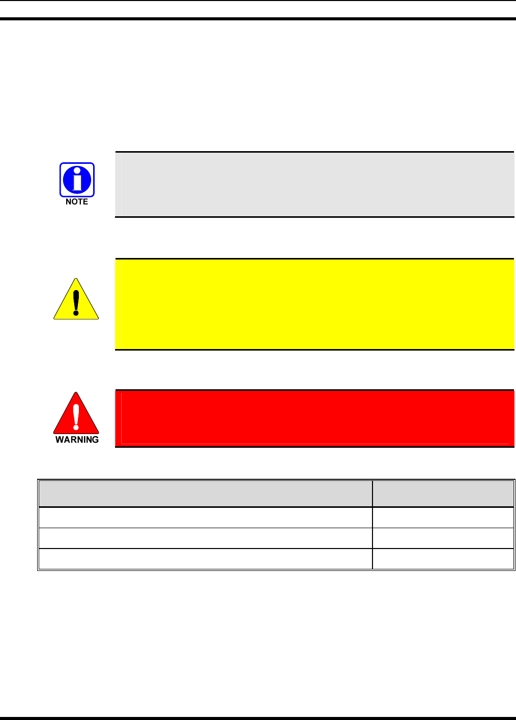
1.2 SAFETY SYMBOL CONVENTIONS
The following conventions are used throughout this manual to alert the user to general safety precautions
that must be observed during all phases of operation, service, and repair of this product. Failure to comply
with these precautions or with specific warnings elsewhere violates safety standards of design,
manufacture, and intended use of the product. M/A-COM, Inc. assumes no liability for the customer's
failure to comply with these standards.
The WARNING symbol calls attention to a procedure, practice, or the like, which,
if not correctly performed or adhered to, could result in personal injury. Do not
proceed beyond a WARNING symbol until the conditions identified are fully
understood or met.
CAUTION
The CAUTION symbol calls attention to an operating procedure, practice, or the like,
which, if not performed correctly or adhered to, could result in damage to the
equipment or severely degrade equipment performance.
The NOTE symbol calls attention to supplemental information, which may improve
system performance or clarify a process or procedure.
The ESD symbol calls attention to procedures, practices, or the like, which could
expose equipment to the effects of Electro-Static Discharge. Proper precautions must be
taken to prevent ESD when handling circuit boards or modules.
The electrical hazard symbol is a WARNING indicating there may be an electrical
shock hazard present.
MM-014714-001, Rev. P2
8
1.3 IMPORTANT SAFETY INSTRUCTIONS
• Read these instructions.
• Keep these instructions.
• Heed all warnings.
• Follow all instructions.
• Do not use this apparatus near water.
• Clean only with dry cloth.
• Do not block any ventilation openings. Install in accordance with the manufacturer’s instructions.
• Do not install near any heat sources such as radiators, heat registers, stoves, or other apparatus
(including amplifiers) that produce heat.
• Do not defeat the safety purpose of the polarized or grounding-type plug. A polarized plug has two
blades with one wider than the other. A grounding type plug has two blades and a third grounding
prong. The wide blade or the third prong is provided for your safety. If the provided plug does not fit
into your outlet, consult an electrician for replacement of the obsolete outlet.
• Protect the power cord from being walked on or pinched particularly at plugs, convenience
receptacles, and the point where they exit from the apparatus.
• Only use attachments/accessories specified by the manufacturer.
• Unplug this apparatus during lightning storms or when unused for long periods of time.
• Refer all servicing to qualified service personnel. Servicing is required when the apparatus has been
damaged in any way, such as power-supply cord or plug is damaged, liquid has been spilled or
objects have fallen into the apparatus, the apparatus has been exposed to rain or moisture, does not
operate normally, or has been dropped.
• Warning: The lightning bolt signifies an alert to the user of the presence of un-insulated “dangerous
voltage” within the product’s enclosure that may be of significant magnitude to constitute a risk of
electric shock to persons.
• Warning: The exclamation point alerts the user to the presence of important operation and
maintenance (service) instructions in the literature accompanying the product.
• Outdoor Use Warning: To reduce the risk of Fire or Electric Shock, Do Not Expose This Apparatus
to Rain or Moisture.
• Wet Location Warning: Apparatus shall not be exposed to dripping or splashing and no objects
filled with liquids, such as vases, shall be placed on the apparatus.
The CS-7000 contains no user-serviceable parts. Only authorized service personnel should
open the unit. Obey all warning labels. If you do not follow these instructions you may risk
electric shock, and/or damage to the equipment.

MM-014714-001, Rev. P3
9
2 SPECIFICATIONS1
MODELS
CT-013892-001: Control Station, Local Control, Desktop
CT-013892-002: Control Station, Remote Control, Desktop
CT-013892-003: Control Station, Remote Mount
FRONT PANEL CONTROLS AND FEATURES
Local Control Desktop Station: DC Power LED, Speaker
Remote Control Desktop Station: DC Power LED, Speaker, Station Microphone Jack, Station
Volume Control, VU Meter, Intercom Switch, Remote Switch
Remote Mount Station: DC Power LED
REAR PANEL CONNECTORS AND FEATURES
Local and Remote Models
AC Power Input: IEC-302, Unified Power Connector/Fuse/ON-OFF Switch
Antenna Connector: Type-N, 50 Ohm, Female
External I/O (P3): DB-25F, I/O, Small Signal – Direct Function
Serial A (P2): USB, 2.0 Type B, 12 Mbps, Radio Programming Port
Serial B (P6): DB-9F, RS-232C (DCE), Serial Interface, Full Duplex, Hardware
Flow Control, ASYNC and SLIP at 19.2kbps
Remote Models Only
CAN Link (J15): 2-Wire Differential, 120 ohms, V2.0B 500kbps
LINE Input (J18): RJ-11 Tone Remote, 600 ohm,
Line-Input: -30 to 0 dBm (-20 to +11 dBm Securitone level).
Line-Output: 0 dBm.
Computer (J1): RJ-45, 10/100BaseT, Ethernet, to Local PC
LAN (J6): RJ-45, 10/100BaseT, Network, to VoIP Remote Controllers
DIMENSIONS (H x W x D):
Desktop: 3.5 x 17 x 13.1 inches (8.9 x 43.2 x 33.3 cm) excluding 1 in.
(2.54 cm) rubber feet
Rack Mount: 3.5 x 17 x 13.1 inches (8.9 x 43.2 x 33.3 cm)
WEIGHT
w/o Transceiver: 18 lbs (8.2 kg)
w/Transceiver: 24 lbs (11 kg)
1 Specifications listed herein are intended primarily for the use of the service technician. See the appropriate Specifications
Sheet for complete specifications.

MM-014714-001, Rev. P2
10
AC INPUT
Maximum: 120 VAC (240VAC), 4.0 Amps (2 Amps), 400 Watts, 50/60 Hz
Transmit (typical): 120 VAC (240VAC), 2.5 Amps (1.25 Amps), 300 Watts, 50/60 Hz
Receive (typical): 120 VAC (240VAC), 1.2 Amps (0.6 Amps), 100 Watts, 50/60 Hz
ENVIRONMENTAL
Operating Temperature: -30 to +40ºC @ 50% duty cycle
-30 to +60ºC @ 20% duty cycle
Storage Temperature: -40 to +70ºC
Standards: MIL-STD-810F
Test Methods: Low Pressure 500.4/2
High Temperature 501.4/1,2, Category A1
Low Temperature 502.4/1,2 Category C1
Temperature Shock 503.4/1, Categories A1 and C1
Vibration, Non-Operational 514.5/1 Category 2
Shock, Transit Drop 516.5/4
Shock, Bench Handling 516.5/6
Humidity 507.4/2
SAE-J551/15 ESD (Functional) Human Body Model
DUTY CYCLE
Receiver: 100% (per EIA-603)
Transmitter: 20 % (per EIA-603)
SPEAKER
Impedance: 12 ohms
Rated Power: 3 W RMS
Distortion: 5% at rated power from 300-3000 Hz
Buzzes/Rattles: None
Acoustic Output:: 95 dB SPL @ 3 W @ 12 inches @ 1 KHz
Acoustic Response: ± 5 dB from 300-3000 Hz
REMOTE CONTROL MODES (Optional)
Tone Remote Control: 2 or 4-wire Tone Remote Control
Modes: EDACS, P25, OpenSky, and Conventional.
Voice over IP: VoIP Audio with PTT Control.
Modes: EDACS, P25, OpenSky, and Conventional.
Controller Area Network: CAN Interface, Supports up to 4 CAN-Linked peripherals
Modes: OpenSky and Conventional.

MM-014714-001, Rev. P3
11
TRANSCEIVER Specifications determined by the Mobile Radio’s Specifications.
Refer to the applicable M5300/M7300 Mobile Radio Maintenance
Manual.
REGULATORY FCC Part-15 Class B Compliant
FCC Part 90 Compliant (refer to mobile radio manual)
Industry Canada RSS-119 (refer to mobile radio manual)
EN60950 Compliant
CSA22.2 Compliant
MM-014714-001, Rev. P2
12
3 INTRODUCTION
The M/A-COM CS-7000 Control Station provides the latest in digital radio technology via the M/A-
COM M5300 or M7300 mobile radio installed into the Control Station. The station may be equipped to
support one or more of the following operating modes:
• OpenSky® digital operation.
• Enhanced Digital Access Communications System (EDACS®) or ProVoice™ trunked modes.
• APCO Project 25 Phase I compliant Common Air Interface (P25 CAI) trunked radio networking.
• Conventional analog mode.
The CS-7000 Control Station is typically used for voice and data dispatch communications via optional
remotely-connected Desktop Controllers. Remote Desktop Controllers may be connected via any of the
following remote control formats:
• Controller Area Network (CAN) link connection.
• Tone controlled line input.
• LAN-based Voice over Internet Protocol (VoIP) connection.
CAN links are generally limited to 250 feet end-to-end line length, but may utilize an optional fiber-optic-
based CAN Bus Extender for increased separation between the CS-7000 and CAN-linked Desktop
Controllers. Tone Remote Controllers connect via 2-wire or 4-wire line audio connections. VoIP
requires connectivity to a Wide Area Network (WAN) or Local Area Network (LAN).
Figure 3-1: CT-013892-001 Local Control Station with Scan Head (Front View)
Figure 3-2: CT-013892-002 Local/Remote Control Station with System Head (Front View)
MM-014714-001, Rev. P3
13
3.1 VOICE OPERATION
The voice path operates like a traditional dispatch radio, with a microphone to transmit (push-to-talk) and
a speaker to receive. In OpenSky Trunked Protocol and P25 modes, all voice communications are
transmitted in a digital mode. Systems operating in EDACS mode may employ both analog and digital
voice modes, and a data mode.
3.2 OPTIONAL REMOTE CONTROL BOARD
The CS-7000 Control Station may be equipped with the optional Remote Control Board. The Remote
Control Board provides the ability to remotely control the station features such as PTT (transmit), group
and/or channel control, and intercom.
3.2.1 Intercom Operation
Control Stations equipped with the optional Remote Control Board are also equipped with an intercom
function. The intercom function allows voice communications between the Control Station’s operator
and operators at Desktop Controllers connected via the CAN link, VoIP link, or Tone Remote Controllers
connected to the line connector. Even when intercom is activated, incoming network radio calls are still
routed to the speaker in the Desktop Controllers in receive mode (not keyed). In other words, radio calls
are not muted when the Desktop Controller’s intercom function is active (with the exception of the remote
that is keyed and making an intercom transmission).
3.3 RELATED DOCUMENTATION
The following documents contain additional information relative to the CS-7000 Control Station. These
documents may be helpful during the installation and maintenance of this equipment.
Table 3-1: Reference Documents
DOCUMENTATION MANUAL NUMBER
CS-7000 Control Station Operator’s Manual MM-014713-001
CS-7000 Control Station Maintenance Manual MM-014715-001
M5300 Transceiver Operator’s Manual MM-012125-001
M5300 Transceiver Quick Guide when using OpenSky Systems MM-012997-001
M5300 Transceiver Quick Guide when using P25, EDACS, or
Conventional Systems MM-013232-001
M7300 Transceiver Operator’s Manual MM-014718-001
M7300 Transceiver Quick Guide when using OpenSky Systems MM-014368-001
M7300 Transceiver Quick Guide when using P25, EDACS, or
Conventional Systems MM-014369-001
M5300/M7300 Software Release Notes MS-014467-001
Site Grounding and Lightning Protection Guidelines AE/LZT 123 4618/1

MM-014714-001, Rev. P2
14
DOCUMENTATION MANUAL NUMBER
Tower Requirements and General Specifications LBI-39185
Antenna Specifications LBI-38983
CAN Bus Extender MM-009088-001
3.4 TECHNICAL ASSISTANCE
Should the CS-7000 Control Station require repair, or if you have questions or concerns about the
installation of this equipment, contact M/A-COM’s Technical Assistance Center (TAC) using the
following telephone numbers or email address:
• U.S. and Canada: 1-800-528-7711 (toll free)
• International: 1-434-385-2400
• Fax: 1-434-455-6712
• Email: tac@tycoelectronics.com
3.5 CUSTOMER RESOURCE CENTER
Replacement parts can be ordered through M/A-COM’s Customer Resource Center. To order replacement
parts through the Customer Resource Center, call, fax or email our ordering system:
North America:
• Phone Number: 1-800-368-3277 (toll free)
• Fax Number: 1-800-833-7592 (toll free)
• E-mail: customerfocus@tycoelectronics.com
International:
• Asia Pacific: 1-434-455-9223
• Latin America & Middle-East: 1-434-455-9229
• Europe: 1-434-455-9219
• Fax Number: 1-434-455-6685
• E-mail: customerfocus@tycoelectronics.com
MM-014714-001, Rev. P3
15
4 UNPACKING AND CHECKING EQUIPMENT
4.1 MATERIALS
The CS-7000 Control Station includes an AC Power Cord to connect it to standard AC power (120 VAC,
60 Hz). No installation kit is available, as every installation is custom. The CS-7000 is generally used in
conjunction with a Desktop Controller, both of which have accessories that can be installed. Table 4-1
lists equipment top-level part numbers, and Table 4-2 lists available accessories.
The CS-7000 must not be powered up unless an antenna is installed and
connected. An antenna and its cabling must be purchased separately. Antennas and
coaxial cables are typically customized to the installation site. Have site surveys
performed to identify an appropriate antenna and antenna feed line requirements.
4.2 MATERIAL INSPECTION
CAUTION
After removal from the carton, examine the components and installation items for
broken, damaged, loose or missing parts. If any are noted, contact M/A-COM’s
Customer Resource Center immediately to discuss and arrange for the return of the
equipment to M/A-COM for replacement. Refer to Section 3.5 on page 14 for the
Customer Resource Center contact information. Any unauthorized attempts to repair
or modify this equipment will void the warranty and could create a safety hazard.
Upon removing items from the carton and verifying all equipment is accounted for, proceed with the
installation.
Mounting of the CS-7000 and/or antenna in ways other than those described can
adversely affect performance, violate FCC rules on RF exposure, and even
damage the unit, posing a potential safety hazard.
Table 4-1: Catalog, Description, and Part Numbers for the CS-7000 Control Station
DESCRIPTION PART NUMBER
Control Station, Desktop Configuration, Local Control CT-013892-001
Control Station, Desktop Configuration, Remote Control CT-013892-002
Control Station, Remote Configuration, Remote Control CT-013892-003
MM-014714-001, Rev. P2
16
Table 4-2: Accessories for the CS-7000 Control Station
PART NUMBER DESCRIPTION
MC-014121-001 Desktop Microphone
MAMROS0093 Antenna, 800 MHz 6-element Yagi with 8 dBd Gain
AN-025137-004 Antenna, 700 MHz 6-element Yagi with 7 dBd Gain
MAMROS0094 Antenna Mounting Kit, Universal Mount for Yagi Antennas
MAMROS0095 Cable, Coax: Antenna Jumper Kit
DSXL-MA-BF Lightning Protection Device with DC Blocking (PolyPhaser DSXL-MA-
BF), 700 to 2700 MHz, N-male to N-female connectors, elongated
female connector for PolyPhaser BFN or BFD flange mount adapters.
CD-014027-001 CAN Terminator
CA-009562-0R6 Cable, CAN; 0.6 feet, Black, Right-Angle-to-Straight Connectors
CA-009562-006 Cable, CAN; 6 feet, Black, Right-Angle-to-Straight Connectors
CA-009562-030 Cable, CAN; 30 feet, Black, Right-Angle-to-Straight Connectors
CA-009562-090 Cable, CAN; 90 feet, Black, Right-Angle-to-Straight Connectors
CA-009562-250 Cable, CAN; 250 feet, Black, Right-Angle-to-Straight Connectors
CA-011344 CAN Y-Cable, Black, Right-Angle-to-Two Straight Connectors
MAA7-NSU5C Kit, CAN Bus Extender (Includes CAN Bus Extender MD-008577 and
AC Wall Power Supply.) [2 required per optical CAN link.]
TQS3385 Rev. B (min) Radio Personality Manager (Programming Software for P25, EDACS,
OpenSky)
TQS3389 Rev. A (min) Radio Personality Manager (Programming Software for Analog
Conventional and P25 Conventional)
MM-014714-001, Rev. P3
17
5 INSTALLATION
CAUTION
M/A-COM recommends the buyer use only a M/A-COM authorized
representative to install and service this product. The warranties provided to the
buyer under the terms of sale shall be null and void if this product is installed or
serviced improperly, and M/A-COM shall have no further obligation to the buyer for
any damage caused to the product or to any person or personal property.
Prior to installation, ensure that the CS-7000 has been configured for customer usage
such as channels and personality.
5.1 REQUIRED TOOLS AND EQUIPMENT
5.1.1 Tools and Shop Supplies Required to Install the CS-7000
The following is a list of tools required to complete a standard installation:
• Phillips screwdrivers, sizes #1 and #2;
• Flat head screwdrivers, sizes #1 and #2;
• Slip-jaw pliers;
• 3/8” Nut driver;
• Various fasteners; as required.
Special tools needed to construct and/or install optional cables and accessories are listed in the installation
and configuration sections for the option or accessory.
5.1.2 Equipment Required for CS-7000 Configuration
The following is a list of additional equipment needed to configure the CS-7000:
• Personal Computer (PC) with an available USB communication port and running Microsoft®
Windows® XP or Windows Server 2003. OpenSky programming requires a terminal application
software program such as Windows HyperTerminal, and P25, EDACS, and Conventional requires the
programming software listed in Table 4-2 on page 16;
• Standard USB 2.0B computer cable;
• See Table 7-1 on page 45 for a list of test equipment required to perform antenna tests procedures.
5.2 PLANNING THE CS-7000 INSTALLATION
Plan the mounting locations of all components (CS-7000, antenna, and cables) and determine the routes
for all wiring and cables. Consider also the connection of desktop remotes for planning purposes. Follow
all manufacturer requirements and guidelines for the location of components.
For installations with CAN-linked Desktop Controllers which require connection
through the CAN (Controller Area Network) digital interface, pay particular attention
to the routing of CAN cable in the facility. It may be necessary to use plenum-rated
cable for in-building installations. Refer to Section 5.9 that begins on page 27 and/or
consult with TAC to identify the proper cabling.
MM-014714-001, Rev. P2
18
CAUTION
All cables should be installed with a service loop at each end. During the installation,
do NOT bend any cable at a severe angle near a connector. When the installation is
complete, verify no cable is under any tension. Failure to do so may lead to damaged
cables, causing intermittent operation, or complete equipment failure.
CAUTION
Optimal performance is based upon proper mounting techniques. An improperly
installed unit may experience degradation in the quality of communication with the
OpenSky network.
5.3 CS-7000 INSTALLATION
Determine the customer’s preferences, if any, for location of components. Comply with these preferences
insofar as they are consistent with safety, manufacturer specifications, and generally accepted
professional practices.
5.3.1 Desktop Installations
The CS-7000 can be placed upon a desktop, tabletop, or another flat horizontal surface with an adequate
size and weight rating. The unit’s dimensions are 3.5 x 17 x 13.1 inches (8.9 x 43.2 x 33.3 cm) and it
weighs approximately 24 lbs. (11 kg.).
5.3.2 Rack-Mount Installation
The CS-7000 Remote Configuration Station model CT-013892-003 is designed for mounting within a
19-inch rack-mount cabinet. Its height is two rack-units (3.5 inches). Mounting brackets are attached to
the side corners near the front and rear panel of the CS-7000 at the factory.
Figure 5-1: CS-7000 with Remote Control, Front View
MM-014714-001, Rev. P3
19
Figure 5-2: CS-7000 Rear Panel (shown with Remote Control Board installed)
CAUTION
Never place any other equipment directly on top of the CS-7000. The case is not
designed to handle the weight of other equipment.
The CS-7000 must be kept away from sources of heat. Adequate ventilation must
be provided to the air inlet at the rear of the unit where the fan is located and to
the ventilation holes on the rear-sides of the unit.
5.3.3 AC Power Connection
The CS-7000 only supports an AC power connection. Follow these general guidelines:
• Ensure familiarity with AC power input connection, including maintenance of the fuse; and,
• Make certain that cable routing will not damage or interfere with any existing wiring at the
installation location.
In order to accommodate both U.S. and other standards, the CS-7000 can be used at voltages in the range
of 110 – 120 VAC (50/60 Hz) and 220 – 240 VAC (50/60 Hz). The power cord for U.S. applications
(110 – 120 VAC) is included with the CS-7000 when it ships from the factory. For other applications, the
appropriate power cord must be purchased separately. The receptacle at the back of the CS-7000 is an
IEC-320 C14-type connector for accepting a cord with an IEC-320 C13-type plug.
5.3.4 AC Fuse Replacement
In the event that a fuse blows in the CS-7000, disconnect AC power from the unit by unplugging the cord
from the AC power source or by unplugging the cord from the IEC-320-type AC power connector on the
CS-7000’s rear panel, and follow this replacement procedure:
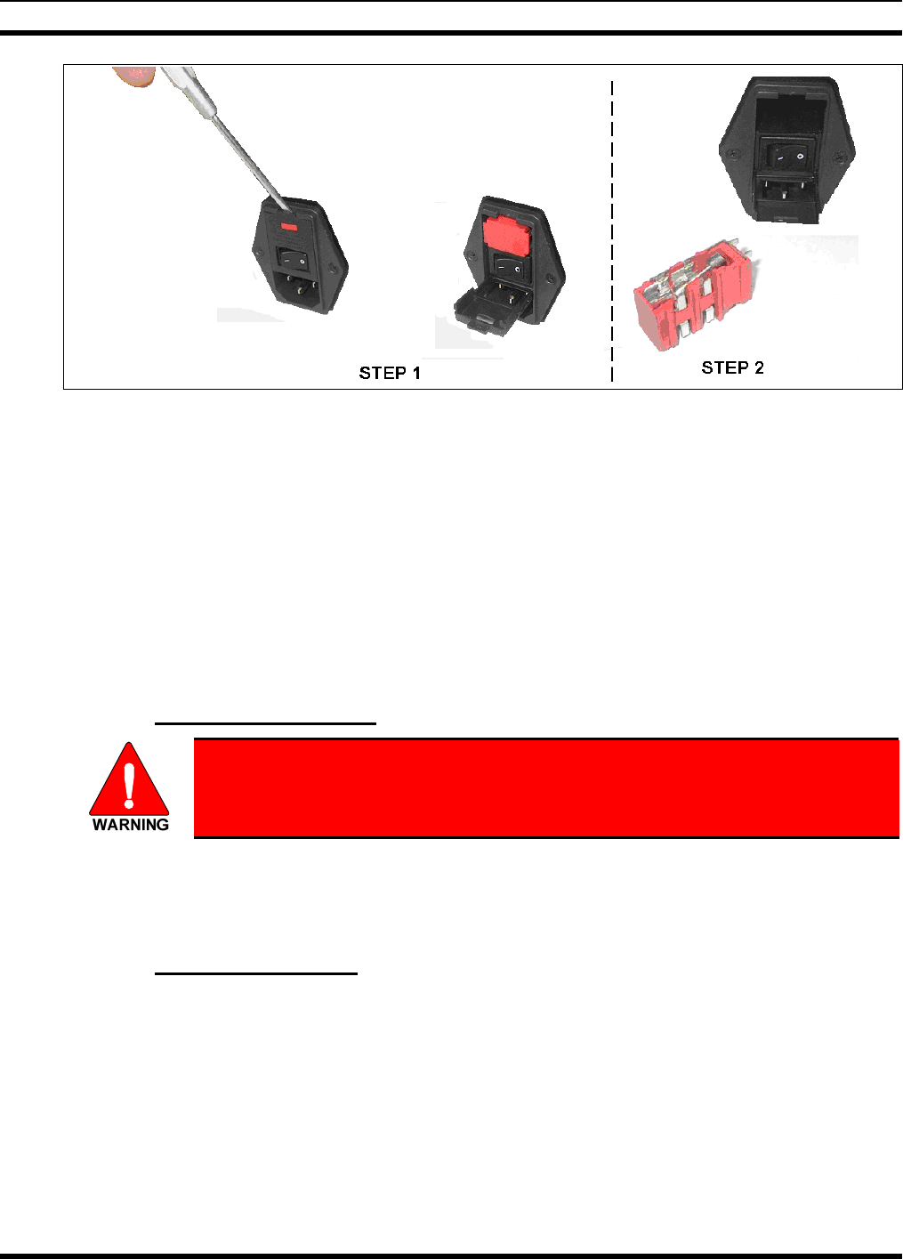
1. As shown in Figure 5-3, slip the tip of a small flat-blade screwdriver into the pry slot at the top of the
AC Power Module and open the fuse assembly door.
2. Remove the fuse holder and replace the blown fuse with a new 4-amp, 250-volt fuse.
3. Re-insert and reseat the fuse assembly until the panel snaps back into place.
4. Reconnect AC power to the unit.
MM-014714-001, Rev. P2
20
Figure 5-3: CS-7000 Fuse Replacement (Rear Panel Views)
5.4 ANTENNA INSTALLATION
Antenna installations vary greatly depending on the type of antenna mounting structure, height, and the
surrounding environment. Professional antenna installation services are highly recommended when
installing and maintaining communications antenna systems. This manual makes no attempt to provide
step-by-step instructions for installing the antenna and supporting structure. Rather, general
recommendations and considerations are provided. Further, where installation instructions provided by
antenna and other related antenna equipment manufacturers differ from this manual, the manufacturer’s
instructions are to be followed at all times. When in doubt, always contact the equipment manufacturer or
M/A-COM Technical Assistance Center for further assistance. Follow all national an d local building
code requirements when installing antenna systems.
5.4.1 RF Safety Information
The antenna must be installed by a qualified antenna professional. Improper
installation of the antenna may lead to poor radio performance, and harmful
exposure to RF electromagnetic energy.
The CS-7000 antenna installation must comply with the FCC RF exposure limits as discussed in Section
1.1. Installation of the antenna for the CS-7000 is to be performed so that no person is within the distance
of maximum permissible exposure limits specified in the FCC regulations. The CS-7000 must be disabled
before antenna maintenance is performed.
5.4.2 General Information
M/A-COM has available several manuals that provide useful information during the installation process.
General antenna installation specifications may be found in M/A-COM’s Antenna Systems Manual,
LBI-38983. Tower Requirements and General Specifications may be found in the Specifications,
Guidelines, and Practices Manual, LBI-39185. And, site grounding must conform to the requirements
found in the Site Grounding and Lightning Protection Guidelines Manual, AE/LZT 123 4618/1.
Failure to follow these instructions will void the product warranty and may expose the end user and others
to excessive Radio Frequency hazards. All antennas should be installed outdoors; and where practical, at
distances from personnel well beyond the minimum allowable distance.
MM-014714-001, Rev. P3
21
5.4.3 Building Installation Considerations
The length of antenna cable should be kept as short as possible to minimize cable loss. Therefore, the CS-
7000 should be installed within the building in a location as close to the location of the outside antenna’s
cable entry as reasonably possible. Remote control options (remote desktop controllers) should be utilized
when the most suitable station installation location is impractical for the intended user(s) access. Consult
with RF equipment installation professionals for more information.
If routed through walls, plenums, or other channeling aids, the cable must be protected
from excessive handling, bending, or rubbing.
5.4.4 Base Station Antennas
The rooftop-mount Yagi antennas listed in Table 4-2 (on page 16) are recommended. Side-mounting onto
a building with other types of directional antennas is also acceptable as long as proper line-of-sight
alignment can be achieved.
For best performance, the antenna should be placed as far away as practical from any other antennas or
structures, and high enough to clear the line-of-sight of major obstructions.
CAUTION
Ensure that feed lines, lightning protection devices, coaxial jumpers and any other
inline RF devices meet frequency and RF power requirements for the specific
installation.
5.4.5 Transmission Lines
Many different RF coaxial cable types can be used for the antenna connection as long as the utilized cable
meets the following minimum requirements. Cable loss, length of cable, antenna type used, etc., are
issues to consider when selecting the type of cable needed. Minimum cable specifications are:
• 50 ohm nominal impedance;
• Minimal RF Loss at frequency range;
• 1.5:1 VSWR (typical);
• 3 dB/100 feet cable loss (maximum); and,
• Weatherproof construction.
CAUTION
Always hand-tighten RF connectors. Do not tighten RF connectors with tools unless
recommended by the connector manufacturer. The use of a torque wrench is
acceptable when the manufacturer of the connector has specified a torque value.
5.4.5.1 Minimum Transmission Line Bending Radius
When Heliax, Superflex, or another similar transmission line is used, always adhere to the minimum
bending requirements provided by the manufacturer (refer to Table 5-1).
MM-014714-001, Rev. P2
22
Table 5-1: Minimum Bend Radius Values for RF Transmission Lines
CABLE SIZE TYPE PART NUMBER MINIMUM-BEND RADIUS
Andrews Corp.
1/4 inch Superflex FSJ1-50A 1 inch (25 mm)
1/2 inch Superflex FSJ4-50B 1.25 inches (32 mm)
1/2 inch Heliax LDF4-50A 5.0 inches (125 mm)
7/8 inch Heliax LDF5-50A 10 inches (250 mm)
1-1/4 inch Heliax LDF6-50 15 inches (380 mm)
1-5/8 inch Heliax LDF7-50A 20 inches (510 mm)
1/4 inch Superflexible SCF14-50J 1 inch (25 mm)
RFS Cablewave Corp.
1/2 inch Superflexible SCF12-50J 1.25 inches (32 mm)
1/2 inch Hardline LCF12-50J 5.0 inches (125 mm)
7/8 inch Hardline LCF78-50J 10 inches (250 mm)
1-1/4 inch Hardline LCF114-50J 15 inches (380 mm)
1-5/8 inch Hardline LCF158-50J 20 inches (510 mm)
5.4.6 Tower Installations
While most Control Station antenna installations are building and roof mounted, occasionally Control
Stations are installed at sites with towers. Always observe all safety instructions and ensure a safe and
proper antenna installation by following all tower manufacturers’ recommendations. In addition to local
building codes, the most current revision of industry standard TIA/EIA-222: Structural Standards for
Steel Antenna Towers and Antenna Supporting Structures must be adhered to during tower and antenna
installations.
5.5 GROUNDING AND LIGHTNING PROTECTION
Proper grounding is necessary, not only for correct functionality and maximum performance, but also for
minimizing damage that may occur from lightning strikes and personnel safety.
Assuming the facility where the CS-7000 Control Station is installed is protected properly from lightning
strikes on the AC power line, the station is still susceptible to damage from lightning through the RF
antenna port, LAN and phone line inputs. The CS-7000 Control Station does not include an integrated
lightning-protection device at the antenna port, so it is recommended to install an external lightning
protection device. Lightning-protection devices are only effective if the connections are made as their
design intended. Follow the manufacturer’s mounting instructions to ensure a properly grounded unit.
A #10 grounding stud is located at the rear of the CS-7000 Control Station. For safety purposes, connect
it to a suitable earth ground per instructions in the M/A-COM Site Grounding and Lightning Protection
Guidelines Manual, AE/LZT 123 4618/1.

MM-014714-001, Rev. P3
23
5.6 BACKUP POWER SOURCES
Due to the great advancements in the industry’s backup power resources, the CS-7000 Control Station
does not provide connections for backup AC or DC power resources. Rather, it is recommended to utilize
commonly available resources discussed in the following sub-sections.
5.6.1 Uninterruptible Power Supplies
It is recommended when a backup AC power source is required for a CS-7000 Control Station installation
to use an Uninterruptible Power Supply (UPS) system. These systems can vary greatly in price, size, and
run time. Well engineered UPS systems monitor the commercial AC power mains for harmful changes in
the power being supplied. Some UPS systems run in “hot standby” mode providing even greater
protection to the equipment connected to the UPS.
5.6.2 Gas/Propane Generators
Generators may be used when the AC power mains are expected to be down for extended periods of time.
However, generators can occasionally produce unwanted fluctuations and power surges that can
potentially damage the power supply in electronic devices. If generators are used, it is strongly
recommended also use a UPS inline between the generator and CS-7000 Control Station as an added layer
of protection from potentially damaging changes in generator power.
5.6.3 Hydrogen Power Systems
Many alternative power products are available in today’s marketplace. Hydrogen power systems are
quickly becoming the main and backup power source of choice for some customers. Hydrogen power
systems are inherent to high reliability with few moving parts, require lower capital costs than combustion
engine generators, and typically have lower life cycle costs than combustion engine generators. They are
environmentally friendly, produce no toxins, can be installed indoors or outdoors, typically have a smaller
footprint and weight than combustion engine generators, and silent running (no noise pollution).
Hydrogen fuel and replacement tanks are commonly available in most all locations.
5.7 CONNECTING VoIP DESKTOP REMOTE CONTROLLERS
The CS-7000 Control Station Remote Controller Board provides VoIP and control capability to the
Control Station. When equipped with the Remote Controller Board, the rear panel of the Control Station
is equipped with a standard RJ-45 Ethernet LAN jack. This jack provides standard Internet Protocol (IP)
based connectivity.
5.7.1 Setting Up the LAN Port for VoIP Connectivity
1. Connect an Ethernet cable from a LAN or WAN system to the LAN connection on the rear panel of
the CS-7000 Control Station.
2. Follow the setup instructions in APPENDIX A to configure the Control Station for VoIP
connectivity.
5.7.2 Setting Up VoIP Desktop Remotes
1. Follow the setup instructions in APPENDIX B to configure IDA model 24-66, and other VoIP
remotes to operate with the CS-7000 Control Station.

MM-014714-001, Rev. P2
24
5.8 CONNECTING TONE REMOTE CONTROLLERS
The CS-7000 Control Station Remote Control Board also has a RJ-11 LINE input connector for Tone
Remote Control applications.
Two-wire describes a single pair of dedicated metallic wires in the form of discrete 600 ohm telephone-
grade wire provided by a customer, 600 ohm dry (quiet line only) telephone-grade line provided by a
telephone company, or the multiplexed equivalent provided by customer owned equipment. This type of
circuit will support the bi-directional transmission of audio signals in the nominal 300 to 3000 Hz
frequency range.
Four-wire describes two pair of (usually) multiplexed dedicated telephone-grade circuits with one pair
going each way. Each pair will support uni-directional transmission of audio signals in the nominal 300
to 3000 Hz frequency range. One pair is usually designated as the SEND pair while the other is
designated as the RECEIVE pair. These circuits may be obtained for voice applications.
5.8.1 Standard Tone Signaling
In tone remote applications, Tone Remote Controllers send specific audio tones at pre-defined levels
down the line where the station assigns the decoded tones to control various functions of the Control
Station. The Control Station may be programmed to allow control of the following functions:
• Repeater Enable (disable)
• Channel Guard Decode Enable (disable)
• Channel Guard Monitor
• Transmit Frequency Selection
• Receive Frequency Selection
• Scan
• Receiver Selection (Auxiliary Receiver selection)
• Auxiliary Output Enable (disable) (Auxiliary Control)
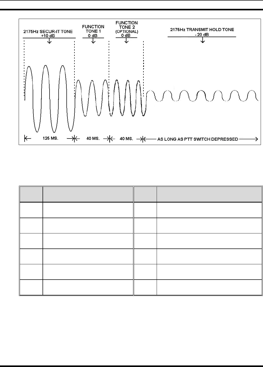
Signaling from a Tone Remote control unit consists of a high level Secur-it tone, followed by the
appropriate medium level function tone, followed by a hold tone if the transmitter is keyed. The tone
control sequence is shown in Figure 5-4.
The Secur-it tone is a +10 dB, 2175 Hz tone that is present for 125 milliseconds. The Secur-it tone is
followed by a 40 millisecond, 0 dB Function tone. The Function tone may be followed by a 2175 Hz
Hold tone at -20 dB level for as long as the PTT is pressed.
5.8.2 Dual Function Tone Signaling
Signaling from a Dual-Function Tone Remote control unit consists of a high level Secur-it tone, followed
by the appropriate one or two medium level function tones, followed by a hold tone if the transmitter is
keyed. The tone control sequence is shown in Figure 5-4.
The Secur-it tone is a +10 dB, 2175 Hz tone that is present for 125 milliseconds. The Secur-it tone is
followed by one or two 40 millisecond, 0 dB Function tones. The Function tones may be followed by a
2175 Hz Hold tone at -20 dB level for as long as the PTT is pressed.
MM-014714-001, Rev. P3
25
Figure 5-4: Tone Remote Control Signaling
The frequency of the Function tone determines the function selected by a tone remote control unit.
Function tones range from 1050 Hz to 2050 Hz, and are spaced 100 Hz apart.
Table 5-2: Typical* Tone Functionality for Tone Remote Control Signaling
TONE
(Hz) FUNCTION TONE
(Hz) FUNCTION
2175 SECUR-IT / TX Hold 1550 Channel Guard Decode or Repeater
Enable
2050 RX Channel Guard Disable (Reset
by PTT) 1450 Channel Guard Decode OFF or Repeater
Disable
1950 TX Group/Freq. No. 1 1350 TX Group/Freq. No. 3 or Aux. Function 1
ON
1850 TX Group/Freq. No. 2 1250 TX Group/Freq. No. 4 or Aux. Function 1
OFF
1750 TX Group/Freq. No 1 or Receiver
No. 1 1150 Repeater Enable**
1650 TX Group/Freq. No 2 or Receiver
No. 2 1050 Repeater Disable** or Scan Simultaneous
Monitor
NOTE: Use of tones below 1050 Hz may degrade system performance due to low frequency noise
components on telephone-grade wire connections.
* The functionality listed for each tone is typical, however may differ for some installations.
** Repeater Enable and Repeater and disable are 1150 Hz and 1050 Hz only when Channel Guard
ON/OFF is present.
MM-014714-001, Rev. P2
26
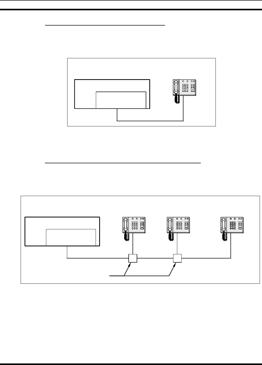
5.8.3 Connecting One Tone Remote Controller
Line loading characteristics of the LINE input of the Control Station must be properly setup. If only one
TRC is connected, the CS-7000 Control Station and the TRC are both considered line terminating end
points. Both devices must have their line impedance set to the low impedance (600-ohm) state for proper
termination. This line interface configuration is illustrated in the following figure:
Tone Remote
Controller
Line Interface = LOW
impedance
CS-7000 Control Station
LINE INPUT
Line Interface = LOW
impedance (600 ohms)
2 or 4-wire line interface
Figure 5-5: Line Input Configured as an Endpoint and Interfaced to One TRC
Refer to Section 6.4 for instructions on configuring the Control Station Line Inputs. Consult installation
instructions for the Tone Remote Controller for configuration instructions.
5.8.4 Connecting More-than-One Tone Remote Controllers
The following figure illustrates the CS-7000 Control Station at the end of a “chain” of paralleled TRCs. In
this configuration, the Control Station and the TRC that is furthest away from the Control Station in
physical cable distance must have their line impedance set to the low impedance (600 ohm) state for
proper termination. All other TRCs must be set to the high impedance state.
Tone Remote
Controller 1
Line Interface = HIGH
impedance
CS-7000 Control Station
LINE INPUT
Line Interface = LOW
impedance (600 ohms)
2 or 4-wire line interface
Tone Remote
Controller 2
Line Interface = HIGH
impedance
Tone Remote
Controller N
Line Interface = LOW
impedance
Note: Tone Remote
Controller N is furthest
away in physical distance.
Splitters or Terminal Distribution
• • • • • • •
Figure 5-6: Configured as an Endpoint and Interfaced to Multiple Paralleled TRCs
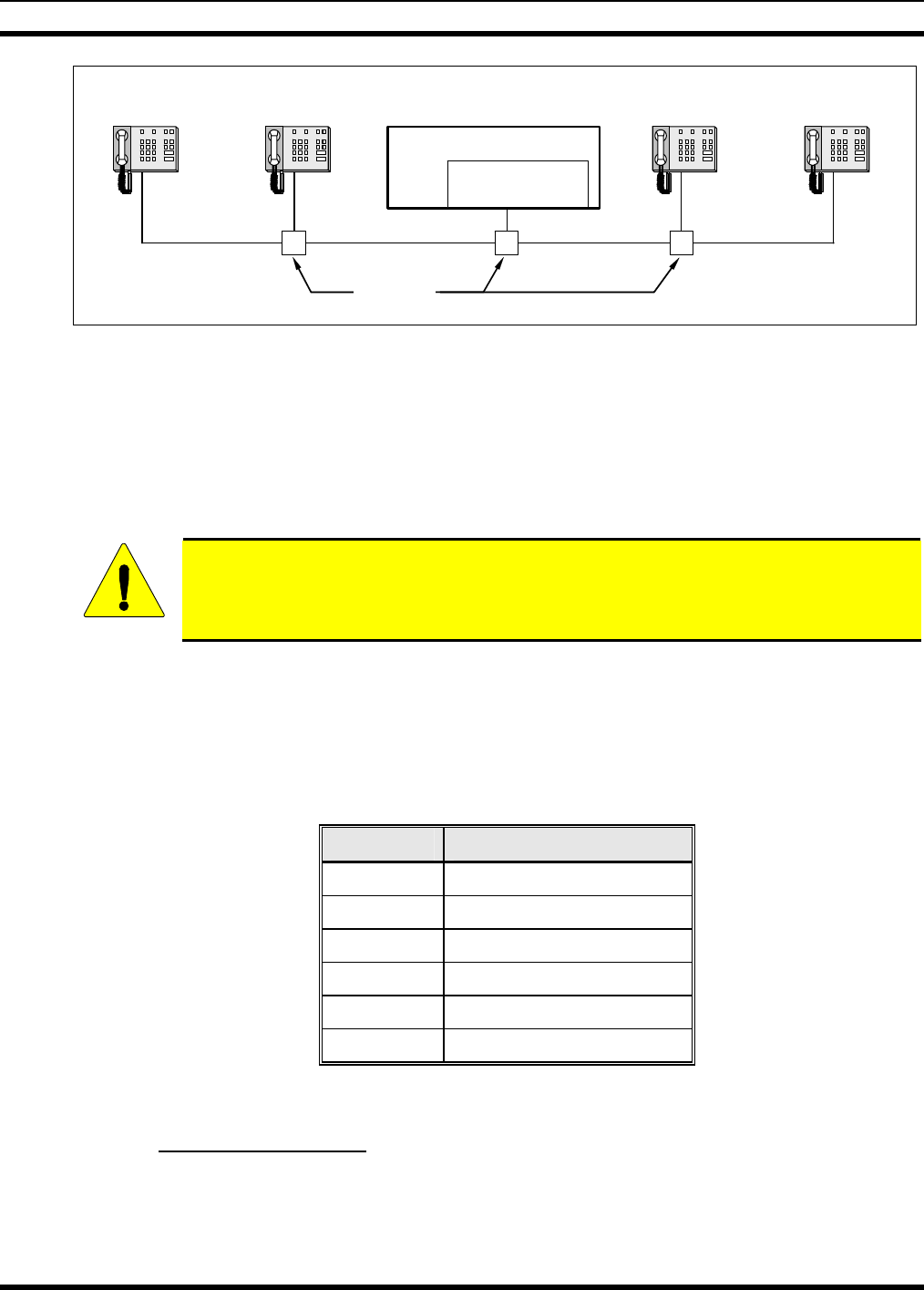
The next figure illustrates the CS-7000 Control Station in the middle of a “chain” of TRCs. In this
configuration, the two TRCs furthest away from each other in physical cable distance must have their line
impedance set to the low impedance (600-ohm) state for proper termination. The Control Station and all
other paralleled TRCs must be set to the high impedance state.
MM-014714-001, Rev. P3
27
CS-7000 Control Station
LINE INPUT
Line Interface = HIGH
impedance
2 or 4-wire line interface
Tone Remote
Controller Y
Line Interface = HIGH
impedance
Tone Remote
Controller Z
Line Interface = LOW
impedance
Note: Tone Remote Controllers
1 and Z are furthest away in
physical distance. (i.e., “at the
ends of the chain”
)
• • • • • • •
Tone Remote
Controller 1
Line Interface = LOW
impedance
Tone Remote
Controller X
Line Interface = HIGH
impedance
• • • • • • •
Splitters or
Terminal
Distribution
Figure 5-7: Control Station in the Middle of a Chain and Interfaced to Multiple Paralleled TRCs
5.8.4.1 LINE Input Connector
A variety of Tone Remote Controllers (TRCs) can be interfaced to the CS-7000 Control Station. The
model supported by M/A-COM is IDA 24-66. The information presented in the following subsections
describes how hardware connections are made to these units, although the manufacturer’s instructions
included with the unit provide the ultimate guidelines. Other TRCs typically follow these installation
approaches.
CAUTION
In all 4-wire TRC installations, connect the Control Station RX audio lines to TRC TX
audio lines, and connect the Control Station TX audio lines to TRC RX audio lines. Line
misconnections will cause control failures to the Control Station.
Table 5-3 describes the pins of the CS-7000 Control Station’s RJ-11 modular jack used for 2-wire and
4-wire line connections. If both 2- and 4-wire connections are available at the TRC, the customer is free
to choose either connection as the CS-7000 Control Station is factory set for 4-wire operation, 4-wire is
recommended, though not required.
Table 5-3: LINE Input Pin-Out
(RJ-11 Modular Jack Labeled “LINE”)
RJ-11 PIN SIGNAL
1 (No Connection)
2 4-Wire +RX IN
3 2-Wire +TX OUT/RX IN
4 2-Wire -TX OUT/RX IN
5 4-Wire -RX IN
6 (No Connection)
5.9 CONNECTING CAN –LINKED REMOTE CONTROLLERS
5.9.1 General Information
Each CS-7000 remote model may be installed using the Controller Area Network (CAN) connection. The
CS-7000 is considered a CAN device, and each CAN-linked desk set in the installation is also considered
a CAN device. Because CAN devices do not have internal terminators, the CAN link must be terminated
at both ends via a CAN terminator.
MM-014714-001, Rev. P2
28
Typically, CAN-linked Desktop Controllers and other devices have two (2) CAN ports to support “daisy-
chaining” of multiple Desktop Controllers, or other CAN devices. The M5300 or M7300 mobile radio
installed into the CS-7000 has two can ports on the rear of the mobile radio. Because CAN devices do
not have internal terminators, the CAN link must be terminated at both ends via a CAN terminator. A
terminator should always be installed on the second CAN port on the rear of the mobile radio (refer to
Figure 5-8 and Figure 5-9) unless a Y-cable is used on the rear of the CS-7000 Control Station (refer to
Figure 5-10). In this case, the CAN terminator on the rear of the mobile radio should be removed and the
furthest CAN device on each side of the Y-cable must be terminated.
Figure 5-8 through Figure 5-10 assumes the total CAN link connections are less than
250 feet in length. If the total connection length must exceed 250 feet, use the optional
fiber-optic-based CAN Bus Extender to extend the CAN link beyond this normal
250-foot limit. Refer to Section 5.9.3 for additional information.
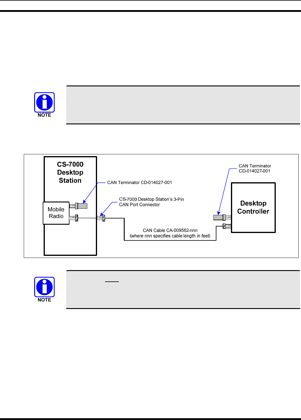
To make CAN connections, visually align the 3-pin male connectors of the cable to the 3-pin female
connectors on each unit. Connect by pushing and twisting the outer housing of the cable connector until a
click is sensed. Do not use excessive force when twisting.
Figure 5-8: Connecting a CAN-linked Desktop Controller
A CAN link must be terminated properly at both ends of a CAN link. The CS-7000
has an internal CAN terminator on the second radio CAN port. A terminator must be
used on the CAN Desktop Controller furthest from the Control Station as shown in
Figures Figure 5-8 and Figure 5-9.
MM-014714-001, Rev. P3
29
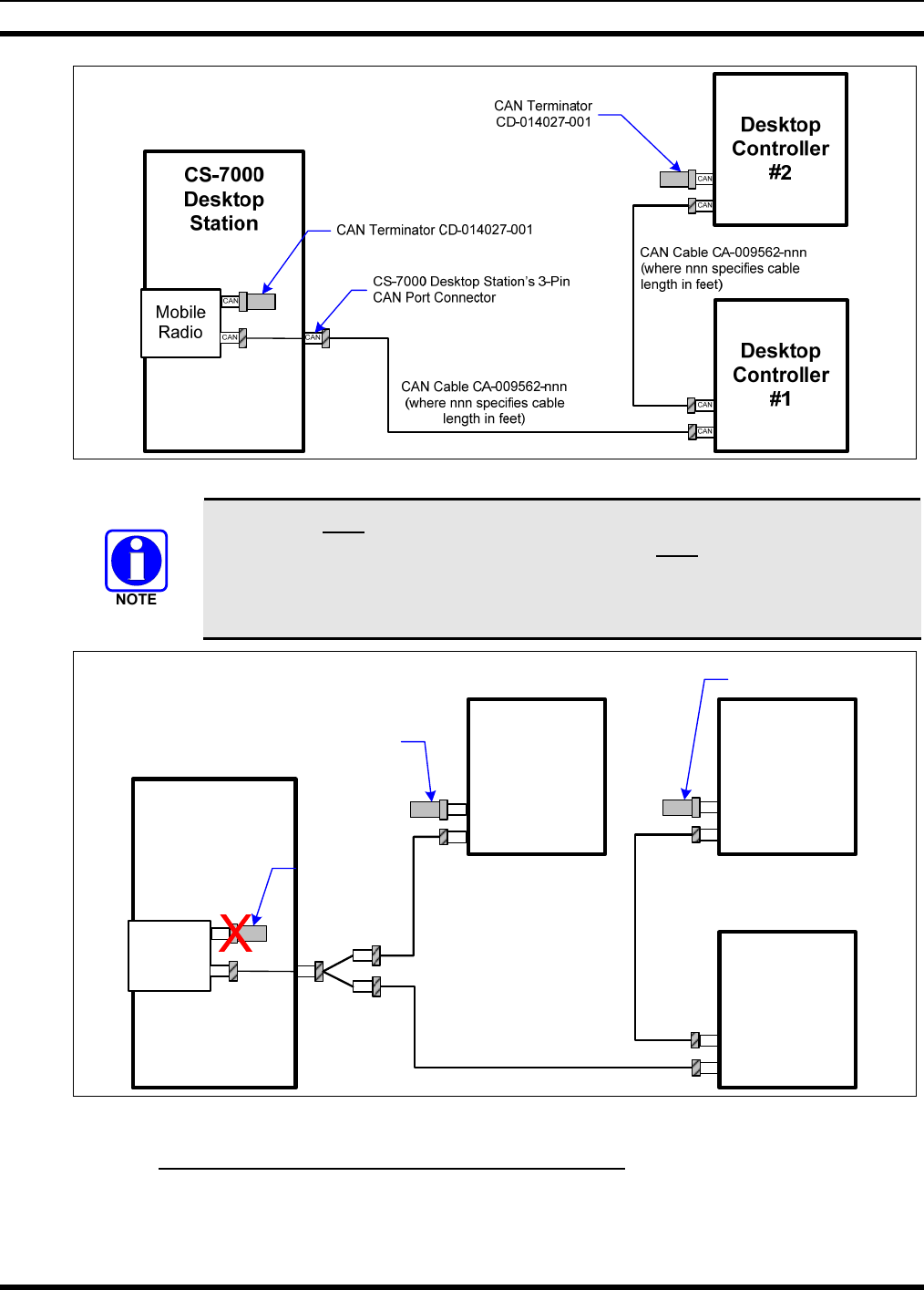
Figure 5-9: Connecting Two or More CAN-Linked Desktop Controllers
A CAN link must be terminated properly at both ends. The CS-7000 has an internal
CAN terminator on the second radio CAN port which must be removed when using a
CAN Y-Cable at the Control Station. A terminator must be used on the CAN Desktop
Controller furthest from the Control Station on each leg of the Y-Cable (refer to
Figure 5-10).
CAN
CAN
Desktop
Controller
#1
CAN Terminator
CD-014027-001
CAN
CAN
Desktop
Controller
#2
CAN
CS-7000
Desktop
Station
Mobile
Radio
CAN
Remove CAN
Terminator
CAN
CAN
Desktop
Controller
#3
CAN
CAN
CAN Terminator
CD-014027-001
CAN Cables: CA-009562-nnn
(where nnn specifies cable
length in feet)
CAN Y-Cable
CA-011344
CAN
Figure 5-10: Connecting a CAN Y-Cable at the Control Station
5.9.2 CAN-Linked Desktop Controller Connections
The Desktop Controller has two CAN ports on its rear panel to support “daisy-chaining” of multiple CAN
devices. When CAN-linked Desktop Controller is in the middle of a daisy chain, two separate CAN
cables connect to the Y-cable (optional, not supplied). When the CAN-linked Desktop Controller is at the

MM-014714-001, Rev. P2
30
end of a chain of devices, one CAN port connects to the previous CAN device and the other port must be
terminated with a CAN Terminator (part number CD-014027-001).
5.9.2.1 Collocated Installations
For installations where the CAN-linked Desktop Controller is near the same location as the CS-7000 and
no routing of cables into walls or through plenums is required, a standard CAN cable can be used. For
cables whose connectors can be routed without the fear of being damaged in routing (e.g., cables do not
need to be snaked through holes), the molded CAN cables are preferred, part number CA-009562-nnn.
See Table 4-2 on page 16 for specific cable part numbers. The “nnn” suffix specifies cable length in feet.
If cable connectors might get snagged or damaged during routing, but a non-plenum-rated cable can be
used, it is recommended that spooled Belden cable part number 1800B (or equivalent) be purchased
separately. However, a CA-009562-nnn CAN cable must also be purchased, as its molded connectors
must be spliced to both ends of the spooled Belden #1800B cable. Recommended splicing instructions are
presented on page 31.
5.9.2.2 In-Wall/Plenum CAN Cable Installations
5.9.2.2.1 Cable Requirements and Routing
As described in the previous section, various lengths of molded CAN cables are available. The standard
molded CAN cable, part number CA-009562-030, is for general use. However, for in-building
applications, this cable does not meet certain safety agency codes for routing through walls and plenums.
For this reason, a plenum-rated cable, Belden cable part number 1801B (or equivalent), can be purchased
separately, by the spool. This cable is recommended for in-wall/plenum CAN cable installations because
of its properties of impedance, shielding, flexibility, and resistance to flame. In-wall/plenum routing faces
the rigors of “snaking” and pulling of the cable. These actions can damage installed connectors.
Therefore, a procedure for routing raw cable through the walls and mating connections reliably is
necessary.
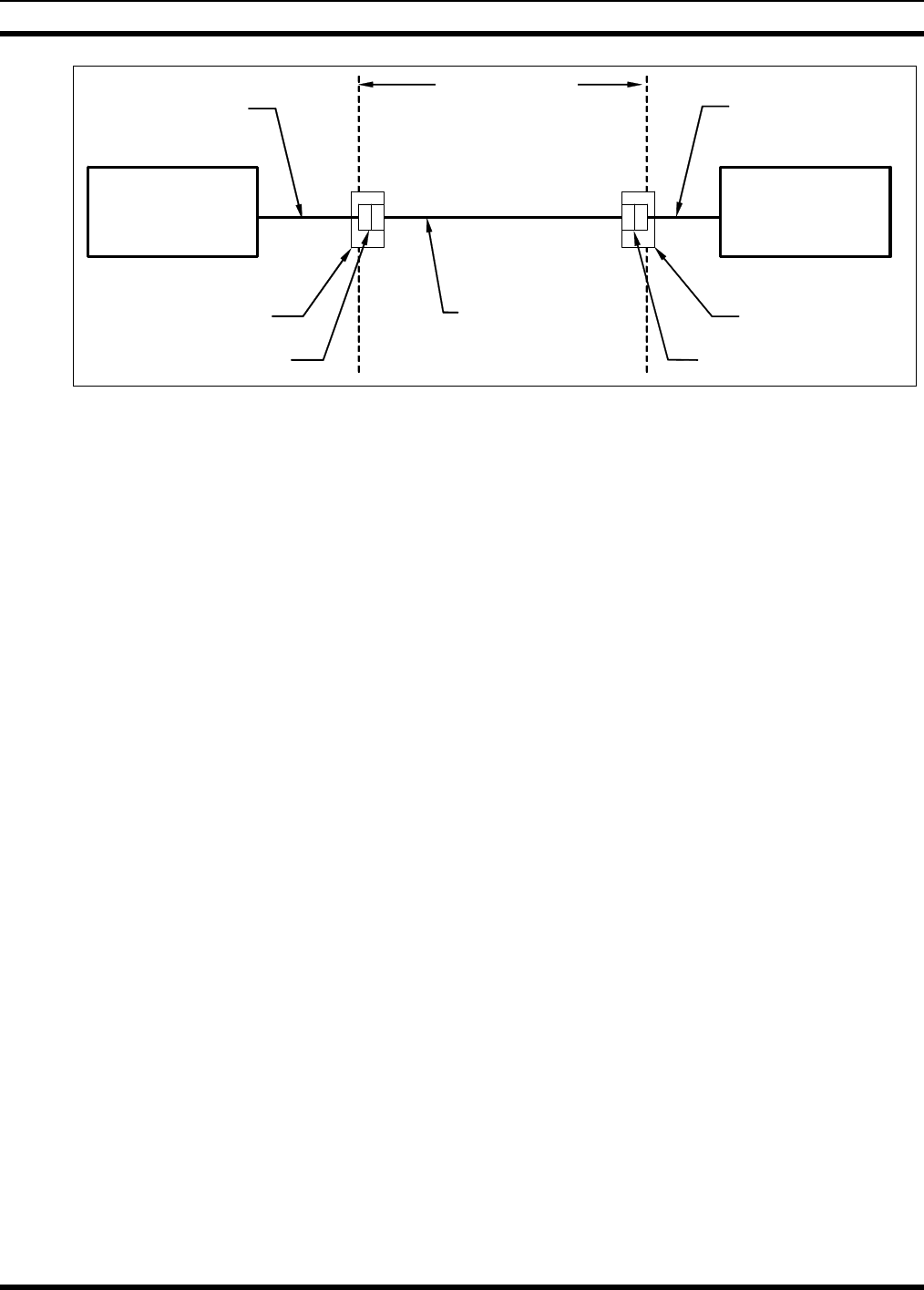
Figure 5-11 illustrates the general concept for connecting the CS-7000 Control Station to the CAN-linked
Desktop Controller via in-wall/plenum CAN cabling. Follow these requirements:
• Materials (e.g., junction boxes, cabling, etc) must meet all building codes.
• The in-wall/plenum cable must be a plenum-rated, shielded, twisted-wire pair of 22-AWG. Belden
part number 1801B cable (or equivalent) is recommended. If the utilized cable does not meet building
codes, it must be dressed or placed inside a conduit (not provided), or some other installation method
must be employed so that it does meet building codes.
• Total physical length of a CAN link, including any amount of cable daisy-chained through multiple
CAN devices cannot exceed 250 feet (76.2 meters). This maximum length assumes the optional
fiber-optic-based CAN Bus Extenders are not employed; see Section 5.9.3 for additional information.
The standard (non-plenum) CAN cable, part number CA-009562-030 for example, is spliced to the
plenum cable using 3-position terminal blocks placed inside junction boxes. Plenum-rated cable is needed
for in-wall/plenum routing, but the standard cable, as long as it isn’t routed through a wall or concealed
ducting, is acceptable for connections to the wall. The standard cable is needed because its solder-type
molded connectors do not accommodate customary in-field installation.
MM-014714-001, Rev. P3
31
CS-7000
Desktop
Station CAN
Port
3-Pole Terminal Block
(Wago #261-423/341-000)
In-Wall Junction Box
One Half o
f
CA-009562-030
(Cut to required length)
CAN
Port
3-Pole Terminal Block
(Wago #261-423/341-000)
In-Wall Junction Box
Other Half of
CA-009562-030
(Cut to required length)
CAN Cable Routing
Throughout Building
Belden 1801B Plenum-
Rated Cable (Maximum
length = 220 feet + the
length cut from the
MACDOS0006-NR030
cable)
Desktop
Controller
Figure 5-11: Connecting In-Wall/Plenum CAN Cable Connections
5.9.2.2.2 Installation Materials
The following materials are required:
• 3-Pole 2-Conductor Terminal Blocks, WAGO part number 261-423/341-
000, or equiv. (2 required);
• Junction boxes (2 required); and,
• Assorted tools for routing cable through walls/plenums and mounting
junction boxes.
5.9.2.2.3 Splicing CAN Cables
The following procedure is recommended for splicing plenum-rated cable to the standard CAN cable:
1. Cut the standard CAN cable (part number CA-009562-030) approximately in half.
2. If not already, power-off both the CS-7000 and the other CAN devices. Both units should remain off
until after the cable installation is complete.
3. Connect each end of the cut CAN cable to the CS-7000 and the Desktop Controller CAN port.
4. Using the cut ends of the cable, determine acceptable locations for wall junction boxes and mount the
two junction boxes using an approved method.
5. Route the cables into the junction boxes and anchor according to building codes.
6. Cut off any excess cable length, allowing at least one foot (0.3 meters) for splicing and servicing. The
total amount of cable removed from both halves is an amount that can be added to the 220 feet of
plenum cable, if needed. For example, if 10 feet of excess length is cut from the standard 30-foot
CAN cable, the plenum cable is allowed to be as long as 230 feet. In any case, do not exceed 250 feet
(76.2 meters) of total CAN cable length.
7. Measure out an amount of spooled plenum cable needed to reach the two junction box splice points
and route it through the building walls, plenums, etc. using approved methods.
8. Route the cable’s ends into the junction boxes and anchor according to building codes.
9. Cut off any excess cable length, allowing a foot or so of length for splicing.
MM-014714-001, Rev. P2
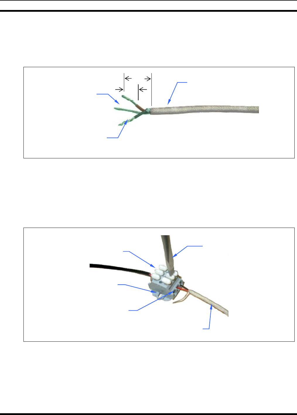
32
10. With a 14-AWG wire stripper, strip off 3/4-inch of the cable’s outer jacket and remove any shield
foil. This dimension is critical, as too much unexposed lead length can have an adverse effect on
performance. Ensure no damage was done to the individual wires.
11. With a 22-AWG wire stripper, strip off 5/16-inch of insulation from each individual wire in the
shielded pair. The third wire in the cable is the shield ground wire—do not cut it. See Figure 5-12.
Figure 5-12: Dimensions for Stripping 2-Wire (with Shield) CAN Cables
12. At both ends of the spooled plenum cable, simultaneously insert the red and black wires into two
poles of the terminal block by simultaneously pushing two adjacent buttons down with a large #2
flathead screwdriver, and guiding the bare end of the wire into the side openings of the terminal
block. Next, release pressure on the buttons while ensuring the bare wires are visible entering the
block’s clamping mechanisms. See Figure 5-13. The order of wires in the terminal block housing
does not matter, but the red and black wires must be next to each other. Consistency between the two
blocks is recommended.
Figure 5-13: 3-Position Terminal Strip Connections
13. Insert the bare shield wire into the third pole of the terminals block by pushing the button down with
the screwdriver, guiding the wire into the opening, and releasing pressure on the button.
14. Strip and connect the CS-7000 and the CAN-linked Control Station’s standard CAN cable wires to
the terminal blocks so matching wire colors on each half of the standard CAN cable will be
electrically connected.
5/16”
3/4”
Stripped Wires
(
1 Pair
)
Shield Wire
Cable’s Outer Jacket
WAGO Terminal
Block Openings
Cable’s Outer Jacket
Push Buttons
Mounting Flange
Screwdriver
MM-014714-001, Rev. P3
33
15. Finish the installation by pushing the terminal block into the junction boxes and covering the boxes
appropriately. Alternatively, the terminal blocks may be secured with small screws (not supplied) at
the mounting flanges.
5.9.3 Connecting a CAN Bus Extender (Fiber Optic Cable Installations)
The optional fiber-optic-based CAN Bus Extenders must be employed in any connection exceeding 250
feet. When using CAN Bus Extenders to connect a CAN-linked Desktop Controller to the CS-7000, one
extender must be co-located with, and connected directly to, the CS-7000. Another CAN Bus Extender
must be co-located with, and connected directly to, the CAN-linked Desktop Controller. For installation-
related information, refer to publication number MM-009088-001.
5.10 CONNECTING DEVICES TO THE EXTERNAL I/O
A 25-pin D-sub miniature (DB-25F) connector is located on the rear panel of the CS-7000 Control
Station. This connector is an interconnection-point for various connections to the station such as auxiliary
audio inputs, external PTT, etc.
5.10.1 Local and Remote Speaker – Jumper Configuration
A series of jumpers are located on the Local and Remote (PLUS Board) Control Station interface boards
for configuring internal and external speaker operation. Nomenclatures and functional use of each jumper
is the same for both boards. Refer to Table 5-4 for jumper configurations.
Table 5-4: Interface Board Jumper Configurations
JUMPER BETWEEN
JUMPER FUNCTION Pins 1 to 2 Pins 2 to 3
JP4 Speaker Select Internal Speaker External Speaker
JP7 Station Speaker 2 Single-Ended Balanced
* Default position.
5.10.2 External I/O Connector (P3) Pinout
Table 5-6 and Table 5-6 defines the pinout for the External I/O port on the Local and Remote (PLUS
Board) Control Stations.
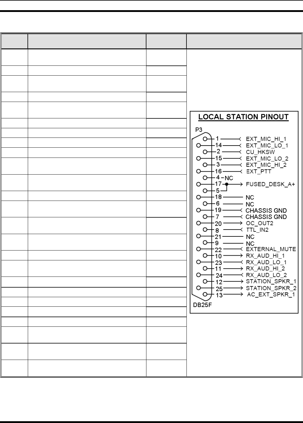
MM-014714-001, Rev. P2
34
Table 5-5: Local Control Station - External I/O Port (P3) Wiring Interconnections
J3 PIN # FUNCTIONALITY PORT PINOUT
1 External Microphone High #1 (Pair to Pin
14) Input
2 Hookswitch (Input) Input
3 External Microphone High # 2 (Pair to Pin
15) Input
4 No Connection
5 Fused A+ from Station PSU, 1.1 Amp
Maximum (Paralleled with Pin 17) Output
6 No Connection
7 Chassis Ground
8 External Logic Input 2 Input
9 No Connection
10 Low Level Receiver Audio Output High 1
(Pair to Pin 23) Output
11 Low Level Receiver Audio Output High 2
(Pair to Pin 24) Output
12 Internal Speaker (See Jumper Chart) Input/Output
13 External Speaker Output (See Jumper
Chart) Output
14 External Microphone Low # 1 (Pair to Pin
1) Input
15 External Microphone Low # 2 (Pair to Pin
3) Input
16 External Microphone PTT Input
17 Fused A+ from Station PSU, 1.1 Amp
Maximum (Paralleled with Pin 5) Output
18 No Connection
19 Chassis Ground
20 OUT2 (Open Collector) Output
21 No Connection
22 External Mute Control (Input) Output
23 Low Level Receiver Audio Output Low 1
(Pair to Pin 10) Output
24 Low Level Receiver Audio Output Low 2
(Pair to Pin 11) Output
25 Internal Speaker Output (+) (See Jumper
Chart) Output
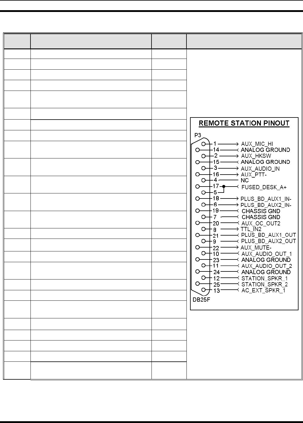
MM-014714-001, Rev. P3
35
Table 5-6: Remote Control Station - External I/O Port (P3) Wiring Interconnections
J3 PIN # FUNCTIONALITY PORT PINOUT
1 Auxiliary Microphone Hi (Input) Input
2 Hookswitch (Input) Input
3 Auxiliary Audio (Input) Input
4 No Connection
5 Fused A+ from Station PSU, 1.1 Amp
Maximum (Paralleled with Pin 17) Output
6 Auxiliary Input 2 (Logic Input) Input
7 Chassis Ground
8 External Logic Input 2 Input
9 Plus Board > Auxiliary Output 2 (Logic
Output) Output
10 Low Level Receiver and/or Station Audio
Output 1 Output
11 Low Level Receiver and/or Station Audio
Output 2 Output
12 Internal Speaker Output (–) (See Jumper
Chart) Input/
Output
13 External Speaker Output (See Jumper
Chart) Output
14 Microphone 1 Audio Ground Input
15 Audio Ground for Mic 2 (Input) Input
16 External Microphone PTT Input
17 Fused A+ from Station PSU, 1.1 Amp
Maximum (Paralleled with Pin 5) Output
18 Auxiliary Input 1 (Logic Input) Input
19 Chassis Ground
20 Receiver Carrier Operated Relay (COR)
Output
21 Auxiliary Output 1 (Logic Output) Output
22 Auxiliary Mute (Input) Output
23 Analog Ground
24 Analog Ground
25 Internal Speaker Output (+) (See Jumper
Chart) Output
MM-014714-001, Rev. P2
36
6 INITIAL SETUP
6.1 CONTROL STATION POWER-UP PROCEDURE
After installing the CS-7000 Control Station and associated accessories per Section 5 and any instructions
supplied with the accessories, the station is now ready to power-up. Perform the following procedures:
1. Connect AC power to the CS-7000. See Section 5.3.3 on page 19 for details.
2. Turn on the CS-7000 via the power switch on its rear panel.
3. Verify power is applied to the CS-7000 by checking for an illuminated green LED on the left-front
panel of the CS-7000.
4. If the optional CAN Bus Extender is employed, connect its “wall cube” power supply to an
appropriate AC power source and then connect the supply’s 24-volt DC cable to the extender’s DC
power input jack.
5. If using a Desktop Remote Controller, follow the instructions supplied with the controller and power-
up the unit.
If using a third-party Tone Remote Controller (TRC), follow manufacturer’s
instructions regarding TRC power up.
6.2 LOCAL CONTROL STATION SETUP AND ALIGNMENT
Local control CS-7000 Control Stations require no additional setup or alignment since the station is not
connected to remote controllers. If the Control Station being setup is a local only station, no further setup
and alignment is required; proceed to Section 7 and perform operational testing.
Stations equipped with the optional remote control board require setup and alignment to meet specific
customer needs. The VoIP, CAN, and Tone Remote applications each provide uniquely definable
features that must be setup, aligned, and tested per instructions in the following sub-sections.
6.3 VoIP (LAN) Setup and Alignment
This section provides a basic step-by-step installation procedure for the VoIP. Detailed information on
adjusting the Control Station VoIP audio levels can be found in section 4.0 Adjustment Procedures.
1. The system should initially be set up and tested on the bench. Use only one remote at first. Additional
remotes can be added later.
2. Connect the TCP/IP Ethernet connection to LAN connector on the back of the Control Station. If the
connection being used is also to be shared with an existing computer, the computer can be connected
to the COMPUTER Ethernet connector on the back of the Control Station. This allows the station
VoIP and the computer to share one network cable.
3. Connect a 24-66 VoIP remote to the network. The Control Station will configure the remote with the
appropriate profile.
4. Receive audio from the base station radio should now be heard at the remote.
5. Press PTT on the remote. The remote should key the base station radio reliably.
6. The remote should also be able to control radio functions such as change channels or systems and
groups on the base station radio if the system is configured for that.
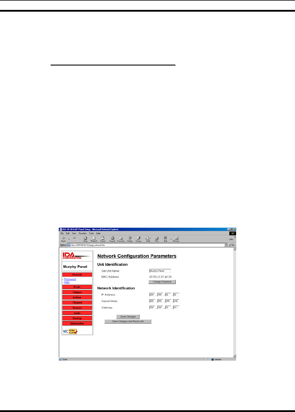
MM-014714-001, Rev. P3
37
7. Program any additional remotes as required. Generally, they should be programmed the same as the
first remote. See the programming procedure for the 24-66 VoIP and for the Control Station.
8. Connect additional remotes to the network. Adjust transmit and receive audio levels of the remotes as
required. Audio from all remotes should be set to the same level.
6.3.1 Programming the VoIP Remote Board
All VoIP Remote board audio and configuration adjustments are accessible using a web browser directed
at the IP Address that is assigned to the board.
The following will explain the adjustment procedure for the 24-66 VoIP. Most audio levels are factory
preset and will, in most cases, not need adjustment. All of the audio adjustments are accessible from a
computer using a web browser. The default address is 10.0.0.200 with the subnet of 255.255.255.0. The
IP address and the subnet address will need to be changed to connect to your network. The user name is
“admin” and the default password is “idacorp”. Once you logon you should change the password to
something else to protect your system. If you are configuring multiple Control Stations or 24-66 VoIP
Remotes, you may need to reset the computer NIC card or restart the computer if the next 24-66 VoIP
your computer is connected to does not respond. The following will explain the adjustment procedure for
the 24-66 VoIP.
6.3.1.1 Programming Parameters
All of the programming and audio parameters are accessible through a WEB browser on a PC that is on
the network accessing the IP Address that is assigned to the Control Station VoIP. The default IP
Address is 10.0.0.200. The default account name is admin. The default password is idacorp. It is
suggested that the password be changed to protect the system. Refer to the Help screens under each of the
configuration parameter headers for more information on programming optio1ns.
6.3.1.2 Network
The screen below shows the Network Configuration Parameters.
6.3.1.3 Radio
The screen below shows the Radio Parameters.
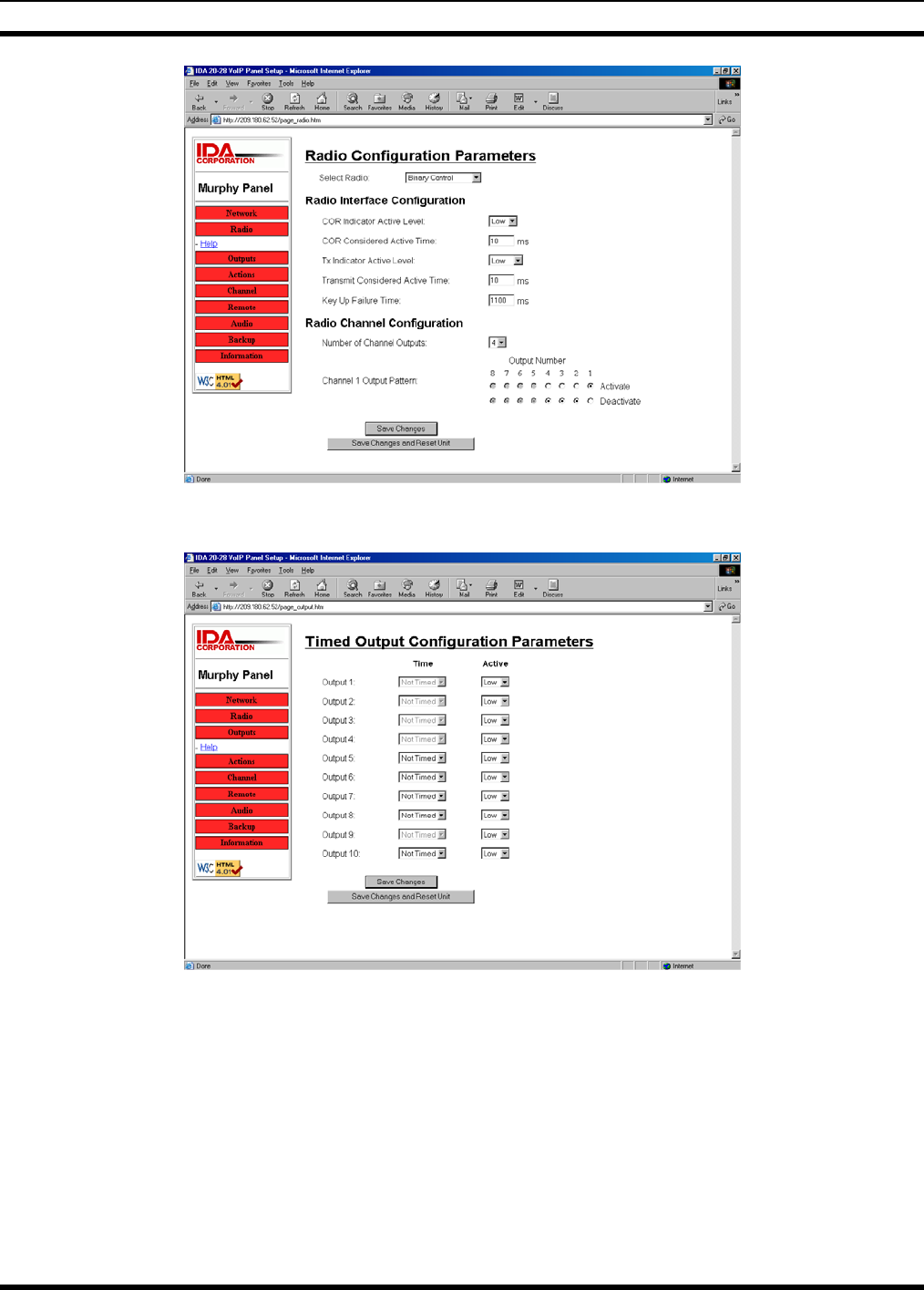
MM-014714-001, Rev. P2
38
6.3.1.4 Output
The screen below shows the Output Parameters.
6.3.1.5 Action
The screen below shows the Action Parameters.
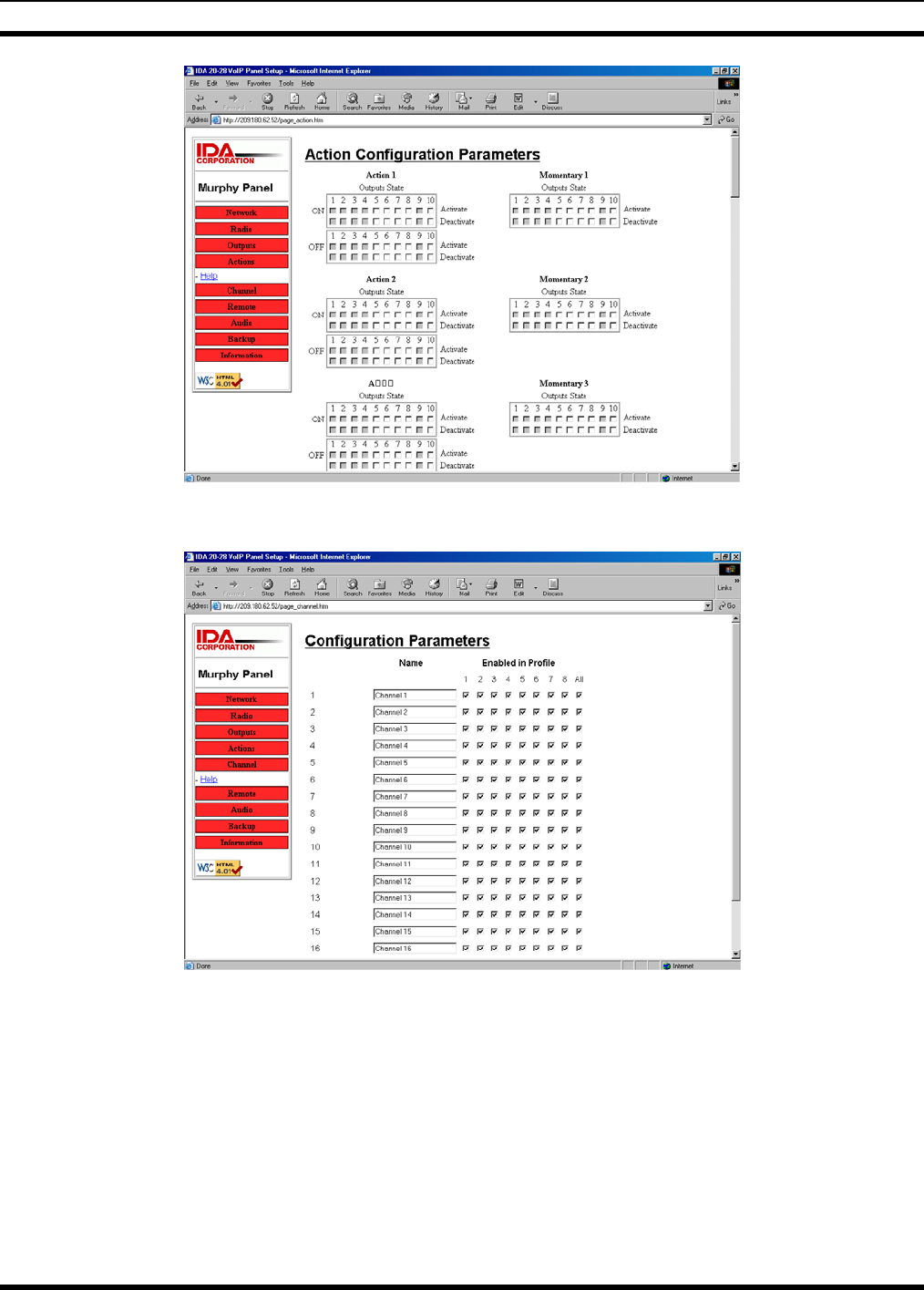
MM-014714-001, Rev. P3
39
6.3.1.6 Channel
The screen below shows the Channel Parameters.
6.3.1.7 Remote Configuration
The screen below shows the Remote Configuration.
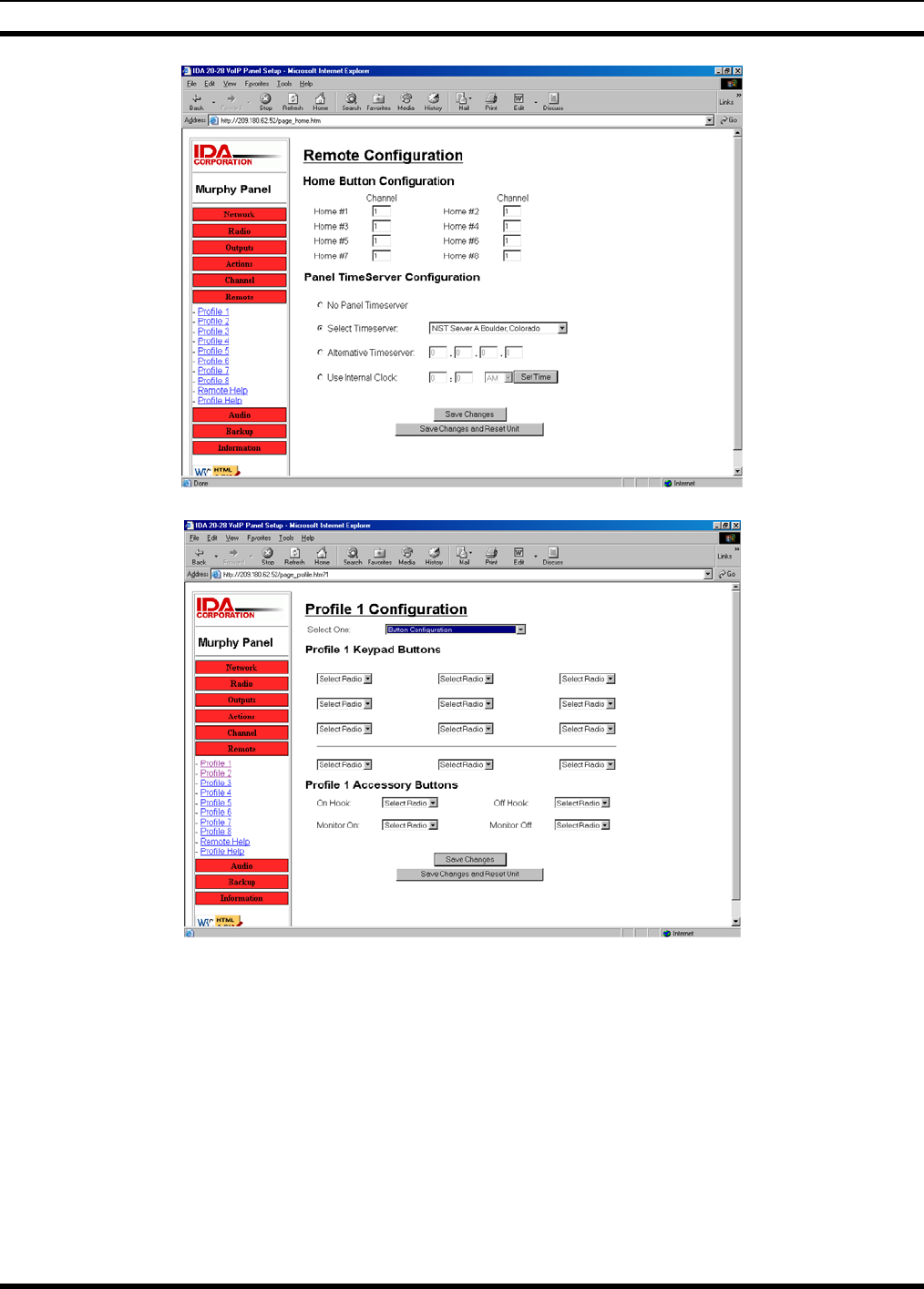
MM-014714-001, Rev. P2
40
The screen below shows the Remote Button Parameters for Profile 1.
The screen below shows the Miscellaneous Configuration for profile 1.
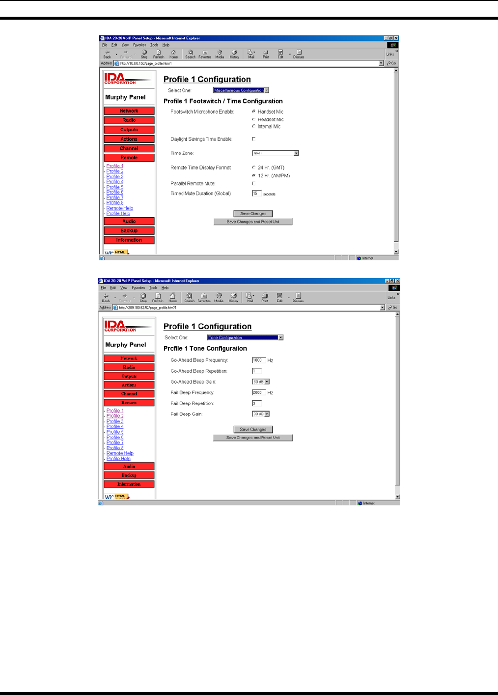
MM-014714-001, Rev. P3
41
The screen below shows the Remote Tone Configuration for profile 1.
The screen below shows the Mini Console Configuration for profile 1.
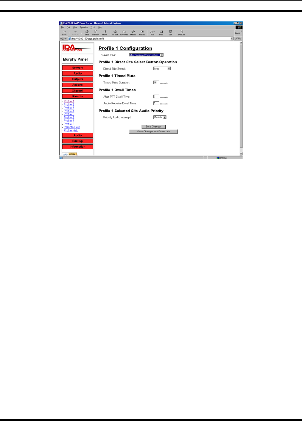
MM-014714-001, Rev. P2
42
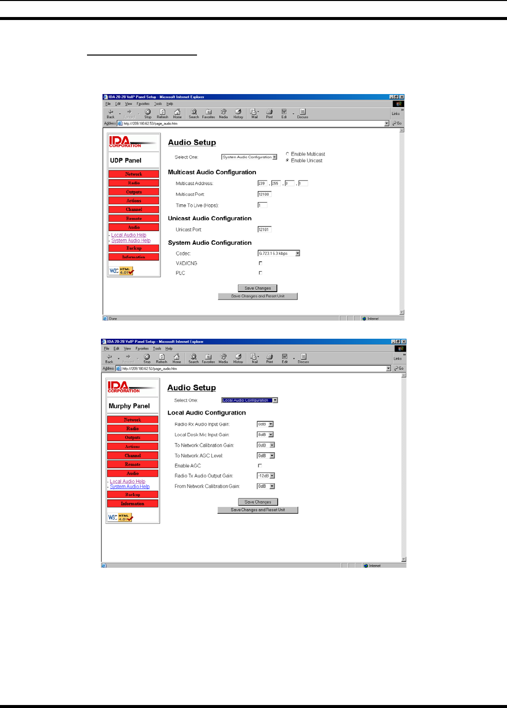
MM-014714-001, Rev. P3
43
6.3.2 Audio Adjustments
6.3.2.1 Audio
The screen below shows the System Audio settings.
The screen below shows the Local Audio settings.
6.3.2.2 Backup
The screen below shows the Backup / Restore feature screen.
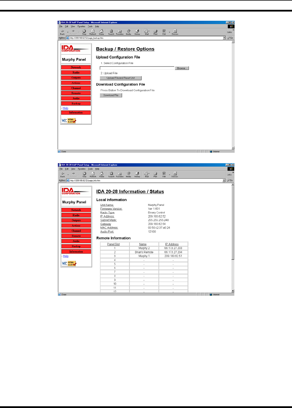
MM-014714-001, Rev. P2
44
The screen below shows the Information / Status screen.
6.4 TONE REMOTE (LINE I/O) SETUP AND ALIGNMENT
TBD.
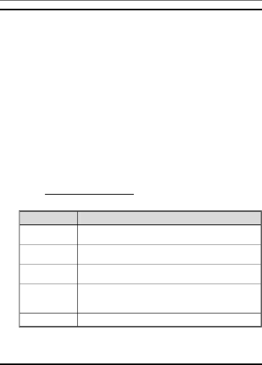
MM-014714-001, Rev. P3
45
7 OPERATIONAL TESTING
This section includes test procedures to verify the performance of the Control Station and its antenna
system installation. Tests must be performed by qualified service personnel with sufficient training and/or
knowledge to ensure the final installation meets requirements defined by the FCC and other regulatory
agencies. Final testing shall ensure that the installation meets FCC MPE requirements (refer to Section
1.1), and Maximum Effective Radiated Power (ERP) requirements (refer to Section 7.2)
7.1 SETUP AND EQUIPMENT TESTING
For EDACS, P25, and OpenSky systems, it is recommended to request the system administrator designate
a talk group on the system that is pre-defined for equipment testing during installation and maintenance.
This will minimize interference on a user’s active talk group. It is also recommended, where possible, to
assign a specific RF channel at the site(s) for the equipment test group; this aide the installers and
technicians by always knowing the specific RF frequency to monitor during testing. Conventional
systems may be left no choice but to test on an active user channel. Is all cases, techniques should be
employed to minimize transmit time during testing.
Setup also includes setting the CS-7000 Control Station transmitter power output level to meet the station
authorization’s Maximum ERP (refer to Section 7.2). After determining the transmitter value for
Maximum ERP, there are three (3) test procedures included in this section which must be performed:
• Verifying TX RF Power Output and Antenna Reflected Power.
• Verifying TX RF Frequency and Modulation (Deviation).
• Over-the-Air Final Testing.
7.1.1 REQUIRED TEST EQUIPMENT
Table 7-1: Required Test Equipment
TEST EQUIPMENT MODEL / PART NUMBER & DESCRIPTION
Peak Power
Wattmeter
• Bird Electronic Corp. Model 4314B (or equivalent) with Type-N female
connectors at input and output ports.
Wattmeter
Slug
• Bird Electronic Corp. Element 50E, 50 watts, 400 – 1000 MHz (or
equivalent).
Service Monitor • Capable of measuring EDACS, P25 and OpenSky frequency and
modulation characteristics.
RF Coaxial
Jumper Cable
• Low loss 50-Ohm Coaxial Cable with Type-N male connectors,
approximately three (3) feet in length.
This cable must have a VSWR below 1.2:1 within the RF pass band.
Audio Tone Generator • Audio tone generator capable of generating a 1000 Hz test tone.

MM-014714-001, Rev. P2
46
7.2 MAXIMUM EFFECTIVE RADIATED POWER
The FCC and other similar regulatory agencies define during station authorization (licensing) the
maximum Effective Radiated Power that may be radiated from the antenna. ERP can be determined by
subtracting feed line losses and adding antenna gain to the transmitter output power.
Once determined, the transmitter’s RF output power must be aligned not to exceed the pre-determined
maximum transmitter power to meet ERP requirements.
7.2.1 Determining Maximum Transmitter Power that Meets ERP Requirement
Antenna gains are expressed relative to a dipole (dBd) or relative to a theoretical Isotropic antenna (dBi).
Antenna gains expressed as dBi are 2.14 dB greater than the dBd value for the same antenna (e.g. 6 dBd
equals 8.14 dBi). ERP values should also be expressed relative to dipoles or Isotropic antennas, EDRP
for dipoles and EIRP for Isotropic antennas.
Therefore, when antenna gain is expressed as dBi, and EDRP is required, 2.14 dB is subtracted in
Part 2.b. of the equation shown below. If antenna gain is expressed as dBd, and EIRP is required, 2.14
dB is added in Part 2.b. of the equation below. If both antenna gain and ERP values are expressed the
same, Part 2.b. of the equation is simply skipped.
Example:
If a site requires a maximum of 50 Watts EDRP using an 8.14 dBi gain antenna, and 3 dB feed line
loss, then the following equation applies:
1. Convert the ERP value from Watts to decibels (dBm): EDRPWatts = 10Log(1000 * EDRP) dBm
50 Watts EDRP = 10Log(1000 * 50)
50 Watts EDRP = 47.0 dBm
2. Sum the antenna gains, feed line losses and dBi or dBd correction factor:
a. Subtract the antenna gain from the ERP value: 47.0 dBm – 8.14 dBi = 38.86 dBm
b. Add or subtract 2.14 dB, if required: 38.86 dBm + 2.14 dB2 = 41.0 dBm
(see above, paragraph two)
c. Add the overall feed line losses3: 41.0 dBm + 3 dB = 44.0 dBm
3. Convert from dBm to Watts: Maximum Transmitter POUT (Watts) = InvLog(dBm-30)/10)
Maximum Transmitter POUT (Watts) = InvLog(44.0 – 30)/10)
Maximum Transmitter POUT (Watts) = 25 Watts
Therefore; for a Control Station installation with an antenna gain of 8.14 dBi, and a feed line loss of 3 dB,
and an EDRP requirement of 50 Watts, the transmitter power output must be set to 25 Watts.
7.2.1.1 For OpenSky Mode of Operation
The transmit RF power level is set by the following:
1. Connect a PC running a Terminal program (19,200kbs, 8-N-1) to the terminal port on the radio.
2 Only add or subtract 2.15 dB if the antenna rating (dBi or dBd) differs from the ERP requirement (EIRP or EDRP).
3 When calculating feed line loss, be sure to include the RF losses presented by coaxial jumpers, lightning protection equipment, the main feed line and any
other in-line devices.
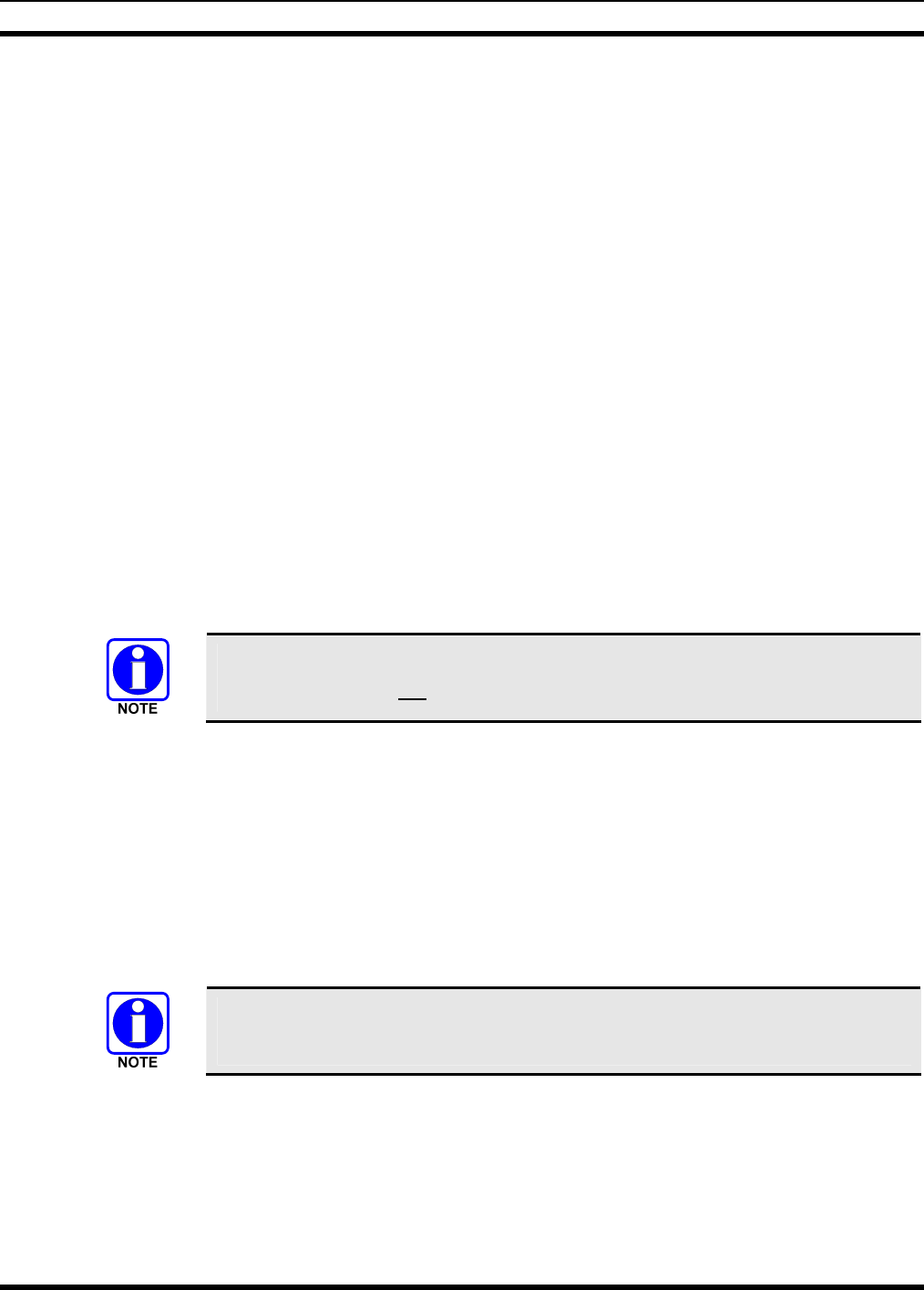
MM-014714-001, Rev. P3
47
2. To set the RF power output to meet the ERP requirement determined in Section 7.2.1, send the
command <at*****> followed by the dBm value of the desired output power (e.g. 25 Watts = 44
dBm = <at*****44>). (Refer to the mobile radio’s Software Release Notes MS-014467-001 for
further setup and programming information.)
3. Send command <at&w3> to save the changed power setting.
4. Success of this setting may be verified while performing Section 7.3.
7.2.1.2 For P25, EDACS, or Conventional Mode of Operation
1. Use the appropriate Radio Personality Manager (RPM) software listed in the accessories Table 4-2 to
read and set the transmit RF power level to the ERP requirement determined in Section 7.2.1.
2. Verify success of this setting while performing Section 7.3.
7.3 VERIFYING TX RF FORWARD AND REFLECTED POWER
After installation of the Control Station is complete, it is required to verify the CS-7000 Control Station’s
forward RF power output and the antenna system’s reflected RF power.
Perform the following tests:
1. Make sure the CS-7000 Control Station is powered down (Off).
2. Disconnect the RF coaxial antenna cable from the rear of the station and connect it to the wattmeter’s
output connector.
3. Connect a coaxial jumper cable between the CS-7000 antenna port and the wattmeter input connector.
A peak-power reading RF wattmeter equivalent to the wattmeter specified in Table
7-1 must be used. Do not use an average or RMS-responding wattmeter.
4. Power-up the CS-7000 Control Station and select the group/channel for performing equipment testing
(refer to Section 7.1).
5. Position the wattmeter’s slug to measure forward RF output power. Rotate it if necessary. The arrow
on the face of the slug must point away from the CS-7000 and towards the antenna for forward power
measurements.
6. Set the wattmeter to measure peak RF power.
7. Key the CS-7000’s transmitter and measure the forward and reflected power; unkey the transmitter
when complete. The forward power should be within the required level to meet ERP requirements
determined in Section 7.2.
Transmit only for as long as needed to take the measurement, then immediately
disable the transmission.
8. If forward and reflected power measurements are within the expected ranges (forward power
equal or less than the required wattage to meet ERP settings from Section 7.2, and reflected
power no more than 10% of measured forward power), record the measured results in the
appropriate space on the data collection form near the end of this manual.
MM-014714-001, Rev. P2
48
CAUTION
IF reflected power is greater than 10% of measured forward power, DO NOT attempt
corrections to the RF output power level to meet ERP values until the high reflected
power measurement is corrected.
If the reflected power measurement is greater than 10% of measured forward power,
check/verify all RF connections, and measure the RF output power again. If problems persist check
the following:
a. Re-check the measurements with a different wattmeter, slug, and jumper cable.
b. Verify the antenna is consistent with the specified frequency range of the CS-7000. For example,
if the CS-7000 is configured for operations in an 800 MHz system, it must be connected to an
800 MHz-capable antenna.
c. Temporarily bypass any lightning protection or other devices installed inline with the antenna and
recheck forward and reflected power.
If problems persist, contact M/A-COM’s Technical Assistance Center for assistance. TAC contact
information is listed on page 14.
If the measured forward power is outside the expected ranges, and the measured reflected
power is no more than 10% of measured forward power, return to Section 7.2.1.1 or Section
7.2.1.2 and reprogram the RF power setting as necessary. If the necessary software change to obtain
the expected RF power level is more than ± 2dB from the expected range, further investigation may
be required.
9. When testing is complete, turn Off the AC power to the Control Station.
10. Disconnect the coaxial cable jumper and wattmeter.
11. Re-attach the antenna coaxial cable directly to the Control Station’s antenna port.
12. Turn On the AC power to the Control Station.
To prevent RF leakage and ensure peak performance, make sure the RF
connectors are tight, but do not over tighten so connector damage will not occur.
Improper antenna and/or antenna cable installation may lead not only to poor
CS-7000 performance but also to harmful exposure of RF electromagnetic energy.
7.4 VERIFYING TX RF FREQUENCY
After verifying forward and reflected power per Section 7.3, verify the CS-7000 Control Station’s
transmitter frequency. It is recommended to have the system administrator designate a talk group on the
system that is pre-defined for test use.
The following frequency test should be performed over-the-air using the station’s antenna while
monitoring the transmitter’s pre-programmed RF frequency:
1. Power-up the CS-7000 Control Station and select the group/channel for performing equipment testing
(refer to Section 7.1).
2. Setup the service monitor as required for measuring TX frequency of over-the-air transmissions.
MM-014714-001, Rev. P3
49
3. Key up the CS-7000 transmitter and measure TX frequency; unkey the transmitter when complete.
4. If the frequency reading is within the expected ranges, record the measured results in the
appropriate space on the data collection form near the end of this manual.
If the frequency reading is not within the expected ranges, try the following:
a. Verify the test instrument settings and calibration date.
b. Recheck the measurement with another test instrument.
If problems persist, contact M/A-COM’s Technical Assistance Center for assistance. TAC contact
information is listed on page 14.
7.5 VERIFYING TX MODULATION
Verify the TX modulation over-the-air using the station’s antenna while monitoring the transmitter’s pre-
programmed RF frequency. Procedures for measuring modulation vary slightly between analog and
digitally modulated transmitters. Perform the following procedure as it applies to the specific mode of
operation for the CS-7000 Control Station under test:
7.5.1 Digital Modulation Modes (EDACS, P25, and OpenSky)
The following modulation test is intended to verify the maximum deviation level of
the digitally modulated RF carrier for regulatory purposes and does not address the
resulting analog audio levels. If the Control Station’s analog levels heard at the
receiving station’s speaker during transmit appear incorrect while performing this test,
refer to the Installation section of this manual and other equipment manufacturer’s
manuals to set the resulting analog audio levels.
1. Make sure the antenna is connected to the CS-7000 Control Station.
2. Power-up the CS-7000 Control Station and select the group/channel for performing equipment testing
(refer to Section 7.1).
3. Setup the service monitor as required for measuring TX modulation of over-the-air transmissions.
4. Key up the CS-7000’s transmitter and measure TX modulation; unkey the transmitter when complete.
5. If the digital modulation reading is within the expected ranges, record the measured results in the
appropriate space on the data collection form near the end of this manual.
If the digital modulation reading is not within the expected ranges, try the following:
c. Verify the test instrument settings and calibration date.
d. Recheck the measurement with another test instrument.
If problems persist, contact M/A-COM’s Technical Assistance Center for assistance. TAC contact
information is listed on page 14.
7.5.2 Analog Modulation Modes
1. Power-up the CS-7000 Control Station and select the group/channel for performing equipment testing
(refer to Section 7.1).
2. Setup the service monitor as required for measuring TX modulation of over-the-air.
3. Connect a tone generator to the microphone input of the transmitter, set to 1000 Hz @ 1Vrms.
Alternately connect a microphone to the Control Station’s microphone connector.

MM-014714-001, Rev. P2
50
4. Key up the CS-7000 transmitter and measure TX modulation using the test tone or by talking into the
microphone. Unkey the transmitter when complete.
5. If the modulation reading is within the expected ranges, record the measured results in the
appropriate space on the data collection form near the end of this manual.
If the modulation reading is not within the expected ranges, try the following:
e. Verify the test instrument settings and calibration date.
f. Recheck the measurement with another test instrument.
If problems persist, contact M/A-COM’s Technical Assistance Center for assistance. TAC contact
information is listed on page 14.
7.5.2.1 Desktop Remote Controllers on Systems Using Analog Modes
1. If one or more Tone, VoIP, or CAN Remote Controllers are connected to the CS-7000 Control
Station, it is recommended to repeat Section 7.5.2 steps 3 thru 5 while modulating the each Desktop
Remote Controller connected to the Control Station.
2. If the modulation reading is within the expected ranges, perform the test for each Remote
Controller connected to the CS-7000 Control Station.
If the modulation reading is not within the expected ranges, verify setup of each remote per the
instructions supplied in the appendices of this manual, or the manufacturer’s instructions supplied
with the Remote Controller.

MM-014714-001, Rev. P3
51
8 COMPLETING THE INSTALLATION
Review and follow guidelines presented in this list before considering the installation complete:
• Verify all electrical connections are connected properly and the associated connector attachment
hardware is tight. Pay special attention to all RF antenna cables, chassis ground cabling, and AC
power cords.
• Verify all fuses are correctly installed and properly rated.
• Verify all electrical cables and wiring are tied, stowed, and protected so they are out of the way of
casual contact, away from sources of extreme heat, and wire chafing cannot occur. Pay special
attention to all RF antenna cables and AC power cords.
• Verify all related mechanical hardware is mounted securely and all respective mounting hardware is
tight.
• Remove all tools and unused hardware from installation area(s).
• Verify the test performance data has been recorded on the data collection form found in APPENDIX
C of this manual.
8.1 FINAL OVER-THE-AIR TESTING
If not already performed during setup and testing, it is recommended to perform live over-the-air testing
on the customer’s active group/channel from the Control Station’s local microphone, and from each
Desktop Remote Controller connected to the Control Station.
Installation of the CS-7000 is now complete!

MM-014714-001, Rev. P2
52
This page intentionally left blank.

MM-014714-001, Rev. P3
A-1
APPENDIX A
CONFIGURING VoIP REMOTE CONTROLLERS

MM-014714-001, Rev. P2
A-2
This page intentionally left blank.
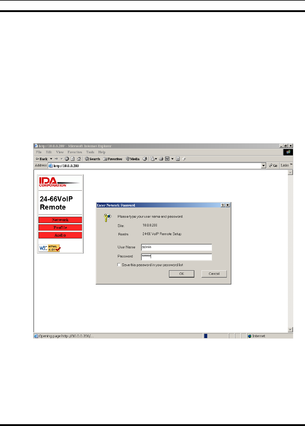
MM-014714-001, Rev. P3
A-3
A.1 IDA MODEL 24-66 VOIP REMOTE CONTROLLER SETUP
A.1.1 Adjustment Procedures
The following will explain the adjustment procedure for the 24-66 VoIP. Most audio levels are factory
preset and will, in most cases, not need adjustment. All of the network settings, profile settings, and audio
adjustment are accessible from a computer using a web browser. The default address is 10.0.0.200 with
the subnet of 255.255.255.0. The user name is “admin” and the default password is ”idacorp”. Before you
connect your computer to the 24-66 VoIP make sure the computers NIC is set to the same IP address
range and local subnet as the 24-66 VoIP. Connect your computer directly to the 24-66 VoIP and use your
web browser to access the logon screen. Once you logon you should configure the network settings to the
IP address, the subnet address, and gateway address that will be used to connect to your network, also
change the password to something else to protect your system. Select the “Save Changes” button before
you continue.
A.1.1.1 Logon Screen Example
Next configure the profile settings, enter the IP address of the Control Station VoIP panel that the 24-66
VoIP remote will connect to and select one of the eight profiles. Select the “Save Changes and Reset
Unit” button. After resetting, the 24-66 VoIP network and profile changes will take affect. If you are
configuring multiple 24-66 VoIP Remotes, you may need to reset the computer NIC card or restart the
computer if the next 24-66 VoIP your computer is connected to does not respond. If you have the 24-66
VoIP Mini Console there will not be a profile menu but a site menu will be in its place so skip to the next
page.
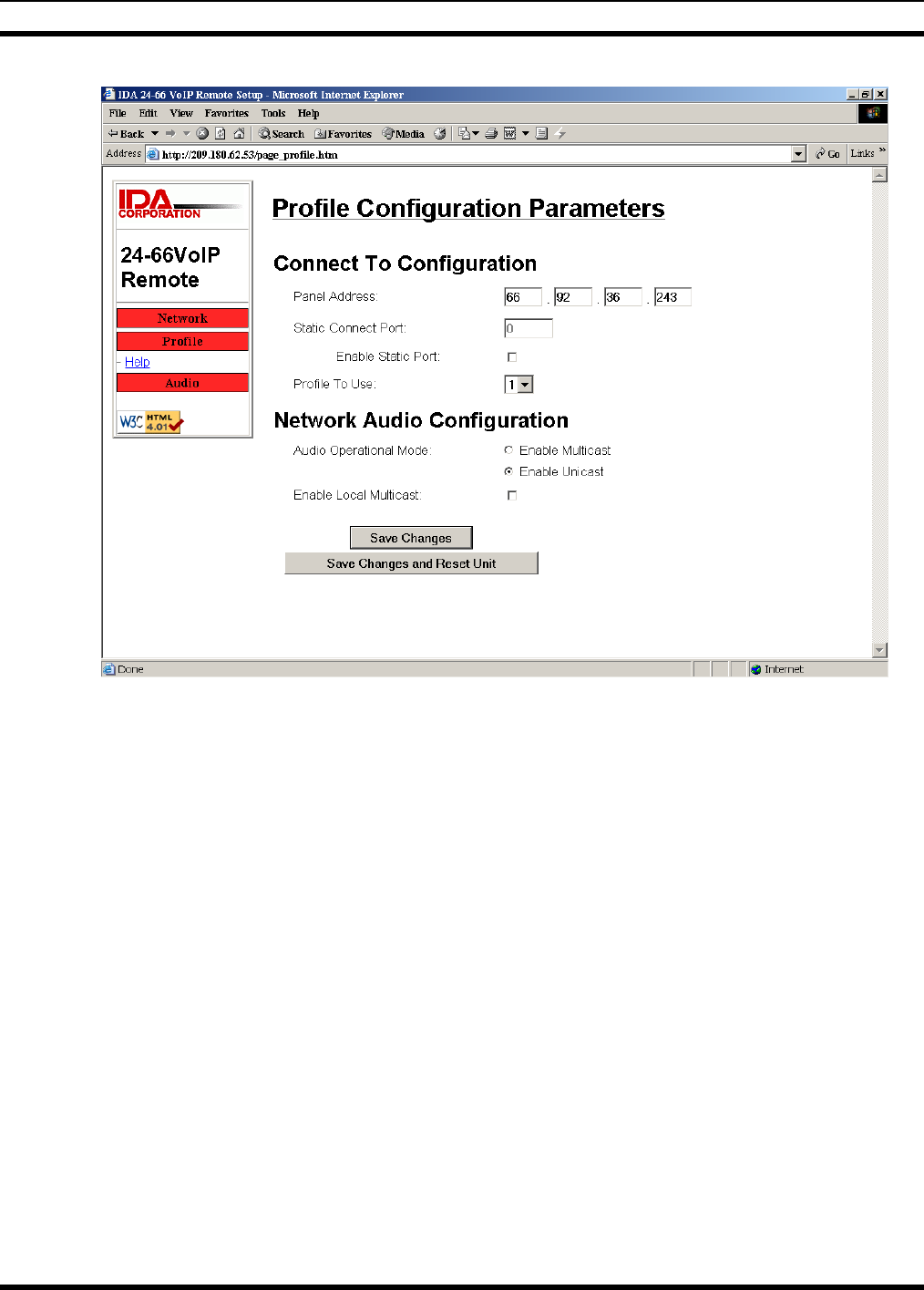
MM-014714-001, Rev. P2
A-4
24-66 VoIP Remote Profile screen example
Next, configure the site settings. Enter the IP address of each Control Station VoIP panel the 24-66 VoIP
Mini-Console will connect to, and select one of the eight profiles. Select the “Save Changes and Reset
Unit” button. After resetting, the 24-66 VoIP network and profile changes will take affect. If you are
configuring multiple 24-66 VoIP Remotes, you may need to reset the computer NIC card or restart the
computer if the next 24-66 VoIP your computer is connected to does not respond.
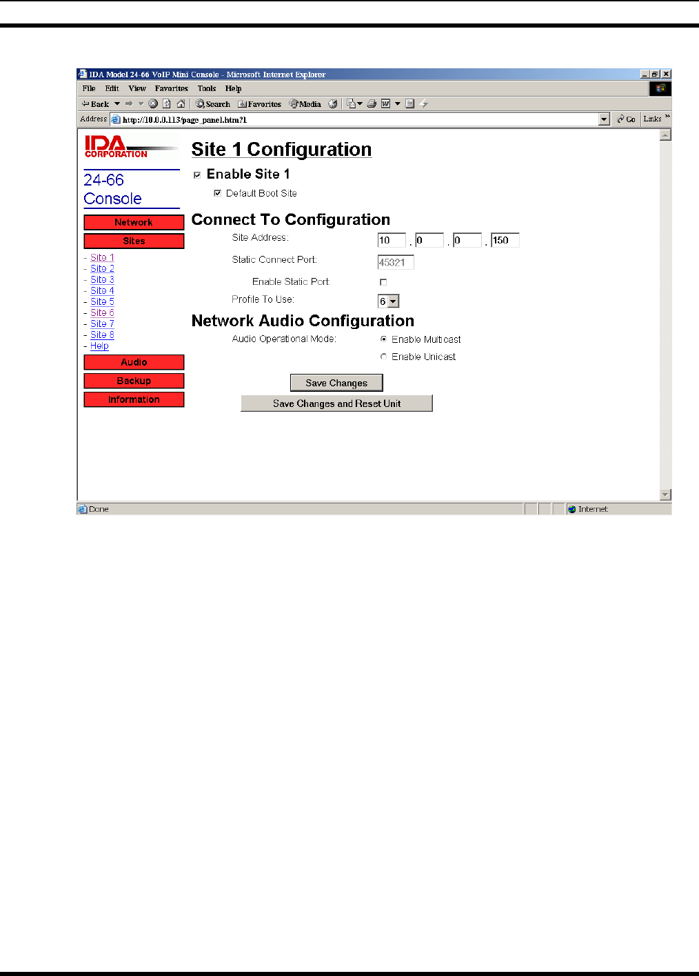
MM-014714-001, Rev. P3
A-5
A.1.1.2 24-66 VoIP Mini Console Site Screen Example
A.1.1.3 Handset/Desk Microphone to Ethernet Level
The handset or desk microphone audio level is adjusted via a web browser. The level can be adjusted
from -4db to 36db in 2db steps.
A.1.1.4 Desk Microphone Output Sensitivity
The audio output level of the desk microphone can be adjusted through a hole in the bottom of the desk
microphone. A small jeweler's flat blade screwdriver will be needed. The adjustment may need to be
made depending upon background noise in the environment where the 24-66 VoIP is located and also
upon the user of the desk microphone and how close and/or loud the user speaks.
A.1.1.5 Internal Microphone to Ethernet Level
The internal microphone audio level is adjusted via a web browser. The level can be adjusted from -4db
to 36db in 2db steps.
A.1.1.6 Headset Microphone to Ethernet Level
The Headset microphone audio level is adjusted via a web browser. The level can be adjusted from -4db
to 36db in 2db steps.
A.1.1.7 Speaker Level
The internal speaker audio level is adjusted via a web browser. The level can be adjusted from -24db to
0db in 6db steps.

MM-014714-001, Rev. P2
A-6
While connected to the system and receiving audio from the highest-level source, adjust the level so that
audio in the speaker is a comfortable listening level. Do not turn it up too high since this will cause
distortion and clipping. The audio should not exceed 3.45 Vrms at the speaker terminals.
A.1.1.8 Handset Earpiece Level
The handset earpiece audio level is adjusted via a web browser. The level can be adjusted from -24db to
0db in 6db steps.
The handset earpiece, headset earpiece, and the base speaker are all controlled by the volume control. It
may be necessary in certain noisy environments to increase the level to the earpiece. While in the noisy
environment and receiving audio from the source with the least level coming in, adjust for a comfortable
listening level with the volume control potentiometer at maximum.
A.1.1.9 Headset Earpiece Level
The headset earpiece audio level is adjusted via a web browser. The level can be adjusted from -24db to
0db in 6db steps.
The headset earpiece, handset earpiece, and the base speaker are all controlled by the volume control. It
may be necessary in certain noisy environments to increase the level to the earpiece. While in the noisy
environment and receiving audio from the source with the least level coming in, adjust for a comfortable
listening level with the volume control potentiometer at maximum.

MM-014714-001, Rev. P3
B-1
APPENDIX B
INSTALLATION CHECKLIST

MM-014714-001, Rev. P2
B-2
This page intentionally left blank.

MM-014714-001, Rev. P3
B-3
B.1 INSTALLATION DATA SHEET FOR CS-7000 CONTROL STATION
Fill out all information as they apply to the CS-7000 Desktop installation. Items in bold must be filled-in and a
copy given to the equipment owner.
CUSTOMER INFORMATION
Licensee Name: _________________________________________________________
FCC License ID/Call Sign: _________________________________________________________
Customer Contact (Name): _________________________________________________________
Site Address: _________________________________________________________
_________________________________________________________
Site Name: _________________________________________________________
Site Latitude (Deg., Min., Sec.): _________________________________________________________
Site Longitude (Deg., Min., Sec.): _________________________________________________________
INSTALLER INFORMATION
Company’s Name: _________________________________________________________
Installer’s Name(s): _________________________________________________________
_________________________________________________________
Test Technician’s Name: _________________________________________________________
Test Equipment Used: _________________________________________________________
_________________________________________________________
_________________________________________________________
_________________________________________________________
EQUIPMENT/INSTALLATION INFORMATION
CS-7000 Model Number: _________________________
CS-7000 Serial Number: _________________________
Antenna Manufacturer and Model: _________________________________________________________
Antenna Gain: _________ dBi dBd (circle one)
Combined Feed line losses: _________ dB
Max ERP (per station authorization) ________ Watts (refer to Section 7.2)
Maximum Transmitter Power Output to meet ERP requirement: __________ Watts (refer to Section 7.2)
TRANSMITTER MEASUREMENTS (Per FCC rules 47CFR90.215 or similar)
TX RF Power out (Forward): _______ Watts
(refer to Section 7.3)
TX RF Power out (Reflected): _______ Watts
(refer to Section 7.3)
Transmitter Frequency: _______ MHz (refer to Section 7.4)
Transmitter Modulation (Deviation): _______ kHz (refer to Section 7.4)

MM-014714-001, Rev. P2
B-4
This page intentionally left blank.

MM-014714-001, Rev. P3
B-5
WARRANTY
A. M/A-COM, Inc. (hereinafter "Seller") warrants to the original purchaser for use (hereinafter "Buyer") that Equipment
manufactured by or for the Seller shall be free from defects in material and workmanship, and shall conform to its
published specifications. With respect to all non-M/A-COM Equipment, Seller gives no warranty, and only the warranty, if
any, given by the manufacturer shall apply. Rechargeable batteries are excluded from this warranty but are warranted
under a separate Rechargeable Battery Warranty (ECR-7048).
B. Seller’s obligations set forth in Paragraph C below shall apply only to failures to meet the above warranties occurring
within the following periods of time from date of sale to the Buyer and are conditioned on Buyer’s giving written notice to
Seller within thirty (30) days of such occurrence:
1. for fuses and non-rechargeable batteries, operable on arrival only.
2. for parts and accessories (except as noted in B.1) sold by Seller’s Service Parts Operation, ninety (90) days.
3. for P7200, P7100IP, P5400, P5300, P5200, P5100, P3300, PANTHER™ 405P and 605P, M7300, M7200 (including
V-TAC), M7100 IP, M5300 and M3300 radios, two (2) years, effective 10/01/2007.
4. for all other equipment of Seller’s manufacture, one (1) year.
C. If any Equipment fails to meet the foregoing warranties, Seller shall correct the failure at its option (i) by repairing any
defective or damaged part or parts thereof, (ii) by making available at Seller’s factory any necessary repaired or
replacement parts, or (iii) by replacing the failed Equipment with equivalent new or refurbished Equipment. Any repaired
or replacement part furnished hereunder shall be warranted for the remainder of the warranty period of the Equipment in
which it is installed. Where such failure cannot be corrected by Seller’s reasonable efforts, the parties will negotiate an
equitable adjustment in price. Labor to perform warranty service will be provided at no charge during the warranty period
only for the Equipment covered under Paragraph B.3 and B.4. To be eligible for no-charge labor, service must be
performed at a M/A-COM factory, by an Authorized Service Center (ASC) or other Servicer approved for these purposes
either at its place of business during normal business hours, for mobile or personal equipment, or at the Buyer’s location,
for fixed location equipment. Service on fixed location equipment more than thirty (30) miles from the Service Center or
other approved Servicer’s place of business will include a charge for transportation.
D. Seller’s obligations under Paragraph C shall not apply to any Equipment, or part thereof, which (i) has been modified or
otherwise altered other than pursuant to Seller’s written instructions or written approval or, (ii) is normally consumed in
operation or, (iii) has a normal life inherently shorter than the warranty periods specified in Paragraph B, or (iv) is not
properly stored, installed, used, maintained or repaired, or, (v) has been subjected to any other kind of misuse or
detrimental exposure, or has been involved in an accident.
E. The preceding paragraphs set forth the exclusive remedies for claims based upon defects in or nonconformity of the
Equipment, whether the claim is in contract, warranty, tort (including negligence), strict liability or otherwise, and however
instituted. Upon the expiration of the warranty period, all such liability shall terminate. The foregoing warranties are
exclusive and in lieu of all other warranties, whether oral, written, expressed, implied or statutory. NO IMPLIED OR
STATUTORY WARRANTIES OF MERCHANTABILITY OR FITNESS FOR PARTICULAR PURPOSE SHALL APPLY. IN
NO EVENT SHALL THE SELLER BE LIABLE FOR ANY INCIDENTAL, CONSEQUENTIAL, SPECIAL, INDIRECT OR
EXEMPLARY DAMAGES.
This warranty applies only within the United States.
M/A-COM, Inc. M/A-COM, Inc.
1011 Pawtucket Blvd. 221 Jefferson Ridge Parkway
Lowell, MA 01853 Lynchburg, VA 24501
1-877-OPENSKY 1-800-528-7711
ECR-7047F

Tyco Electronics Wireless Systems Segment
221 Jefferson Ridge Parkway
Lynchburg, Virginia 24501
(Outside USA, 1-434-385-2400) Toll Free 1-800-528-7711
www.macom-wireless.com Printed in U.S.A.