HARRIS TR-0049-E M5300 900 MHz Mobile Radio User Manual MM 014714 001rP3
HARRIS CORPORATION M5300 900 MHz Mobile Radio MM 014714 001rP3
UserManual.wiki
>
HARRIS
>
TR-0049-E User Manual
>
Manual 2
Contents
1.
Manual
2.
Manual 1
3.
Manual 2
4.
Operators Manual
5.
Install Manual
Manual 2
Navigation menu
Upload a User Manual
Namespaces
Wiki Guide
HTML
PDF
Info
Views
User Manual
Discussion / Help
Navigation
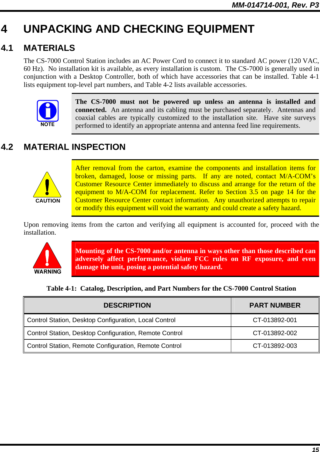
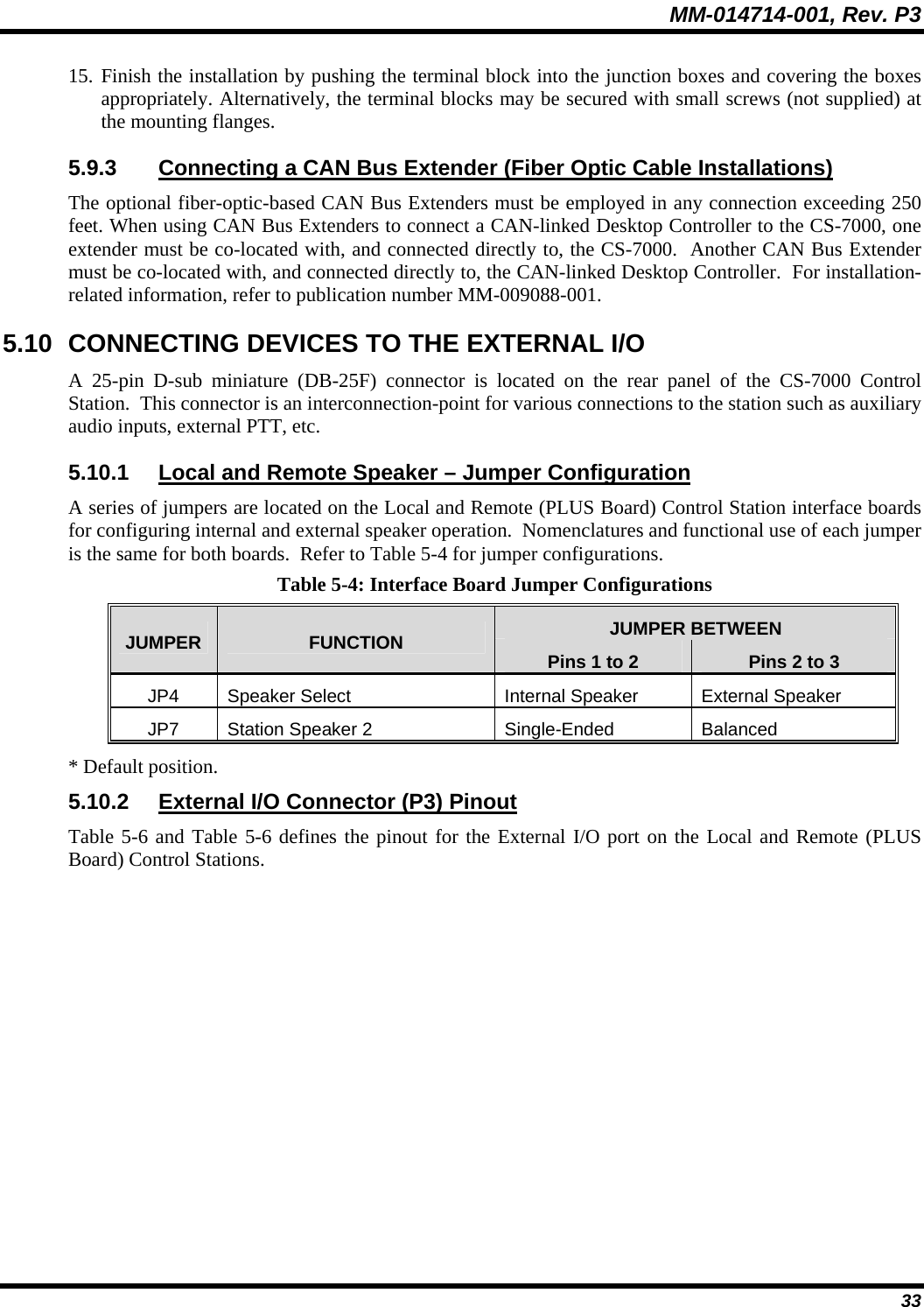
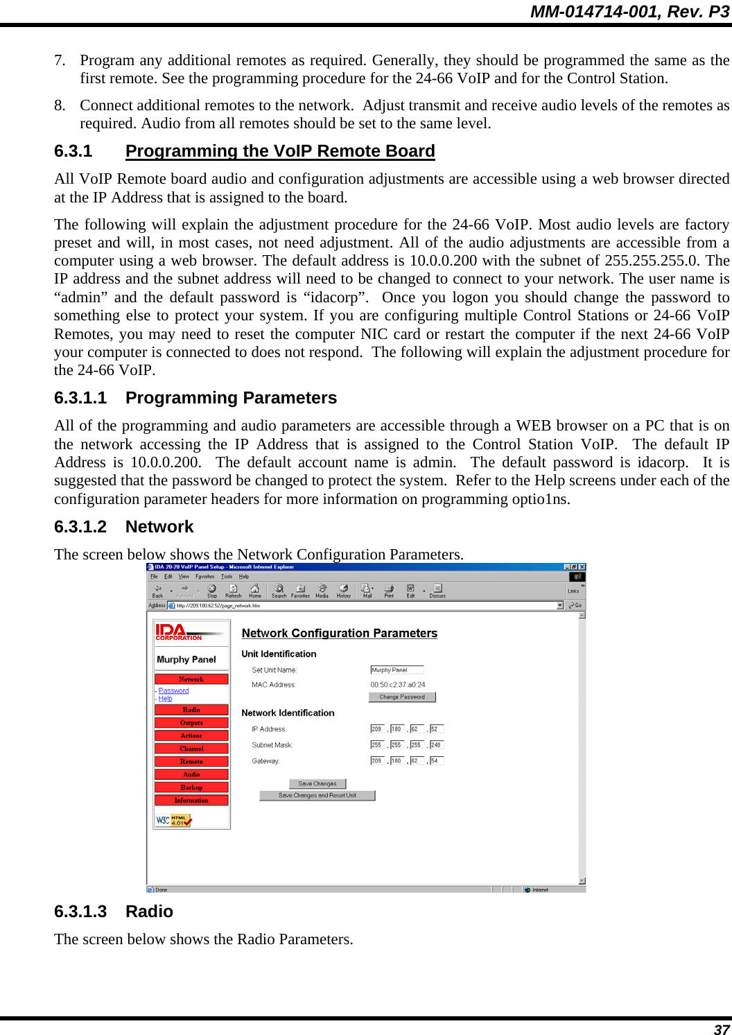
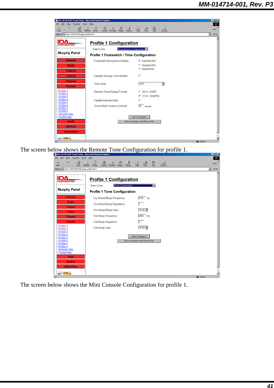
![MM-014714-001, Rev. P2 16 Table 4-2: Accessories for the CS-7000 Control Station PART NUMBER DESCRIPTION MC-014121-001 Desktop Microphone MAMROS0093 Antenna, 800 MHz 6-element Yagi with 8 dBd Gain AN-025137-004 Antenna, 700 MHz 6-element Yagi with 7 dBd Gain MAMROS0094 Antenna Mounting Kit, Universal Mount for Yagi Antennas MAMROS0095 Cable, Coax: Antenna Jumper Kit DSXL-MA-BF Lightning Protection Device with DC Blocking (PolyPhaser DSXL-MA-BF), 700 to 2700 MHz, N-male to N-female connectors, elongated female connector for PolyPhaser BFN or BFD flange mount adapters. CD-014027-001 CAN Terminator CA-009562-0R6 Cable, CAN; 0.6 feet, Black, Right-Angle-to-Straight Connectors CA-009562-006 Cable, CAN; 6 feet, Black, Right-Angle-to-Straight Connectors CA-009562-030 Cable, CAN; 30 feet, Black, Right-Angle-to-Straight Connectors CA-009562-090 Cable, CAN; 90 feet, Black, Right-Angle-to-Straight Connectors CA-009562-250 Cable, CAN; 250 feet, Black, Right-Angle-to-Straight Connectors CA-011344 CAN Y-Cable, Black, Right-Angle-to-Two Straight Connectors MAA7-NSU5C Kit, CAN Bus Extender (Includes CAN Bus Extender MD-008577 and AC Wall Power Supply.) [2 required per optical CAN link.] TQS3385 Rev. B (min) Radio Personality Manager (Programming Software for P25, EDACS, OpenSky) TQS3389 Rev. A (min) Radio Personality Manager (Programming Software for Analog Conventional and P25 Conventional)](https://usermanual.wiki/HARRIS/TR-0049-E.Manual-2/User-Guide-977179-Page-16.png)