HARRIS TR-0049-E M5300 900 MHz Mobile Radio User Manual Install Manual
HARRIS CORPORATION M5300 900 MHz Mobile Radio Install Manual
HARRIS >
Contents
- 1. Manual
- 2. Manual 1
- 3. Manual 2
- 4. Operators Manual
- 5. Install Manual
Install Manual


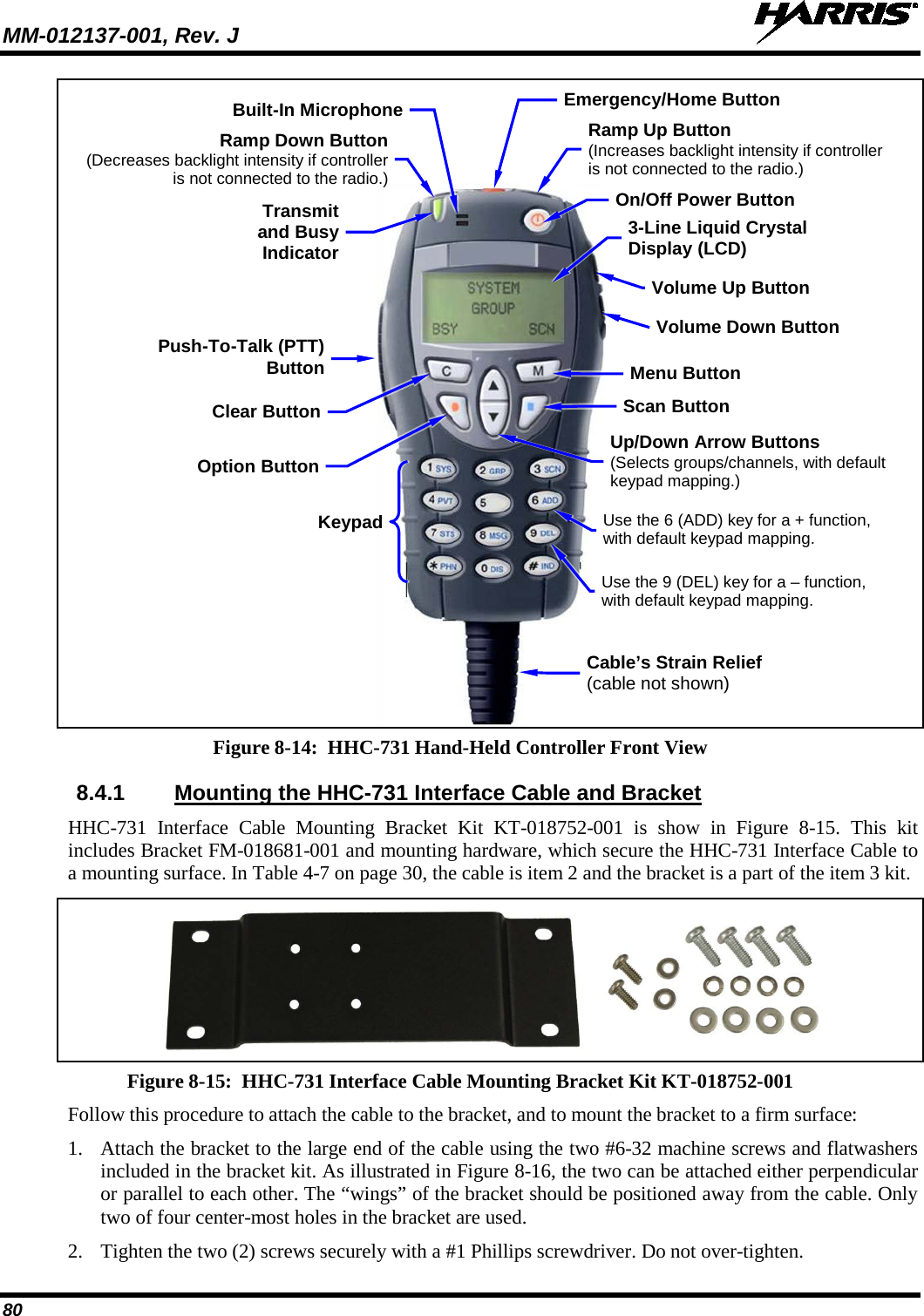
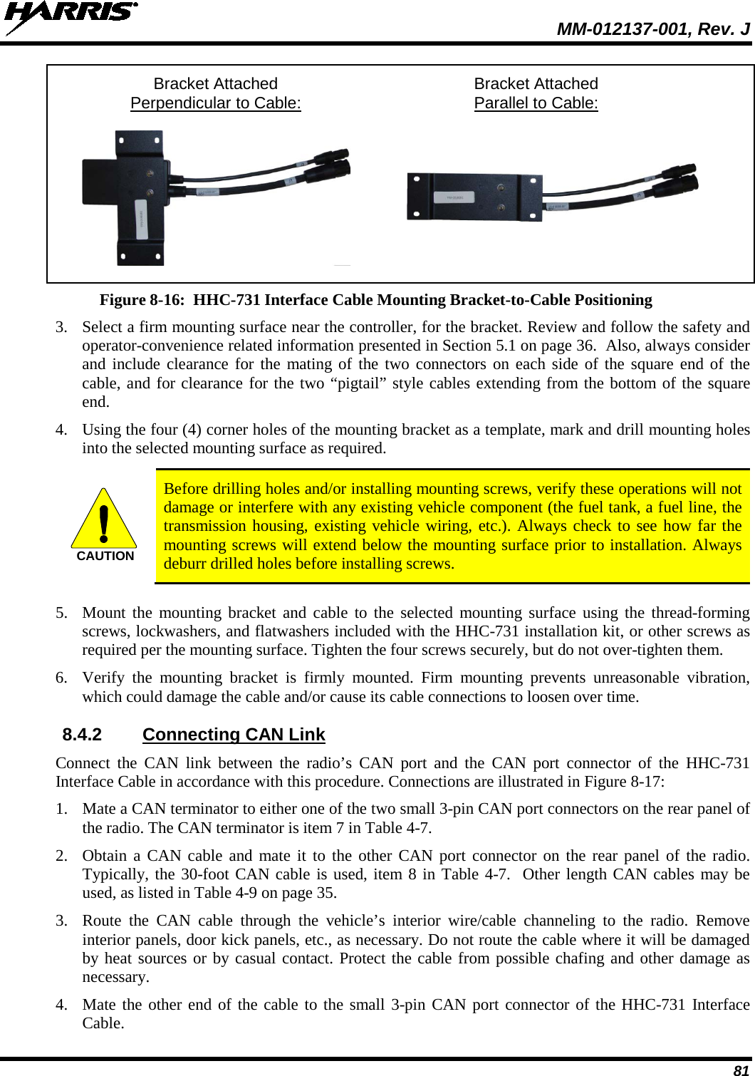
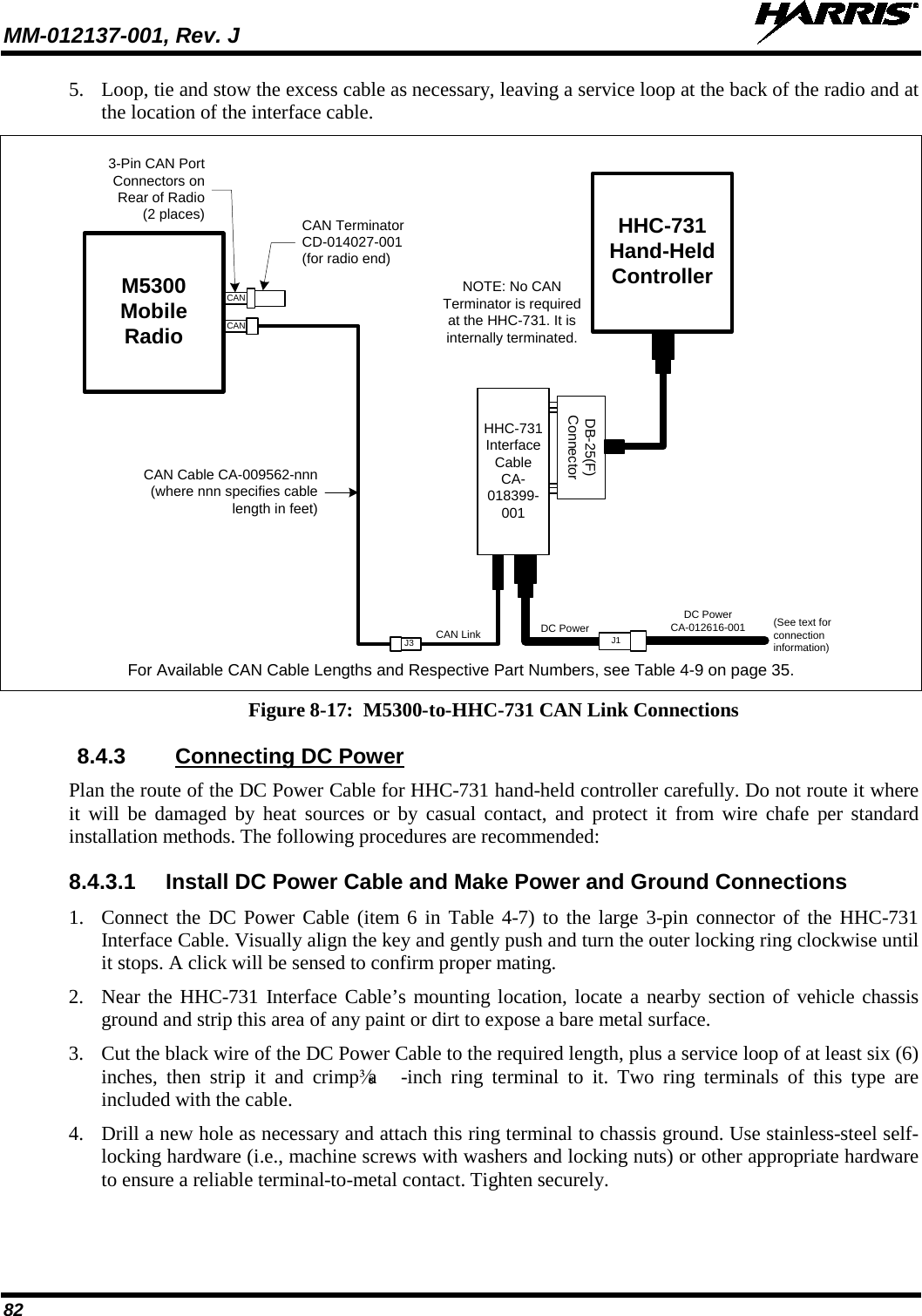
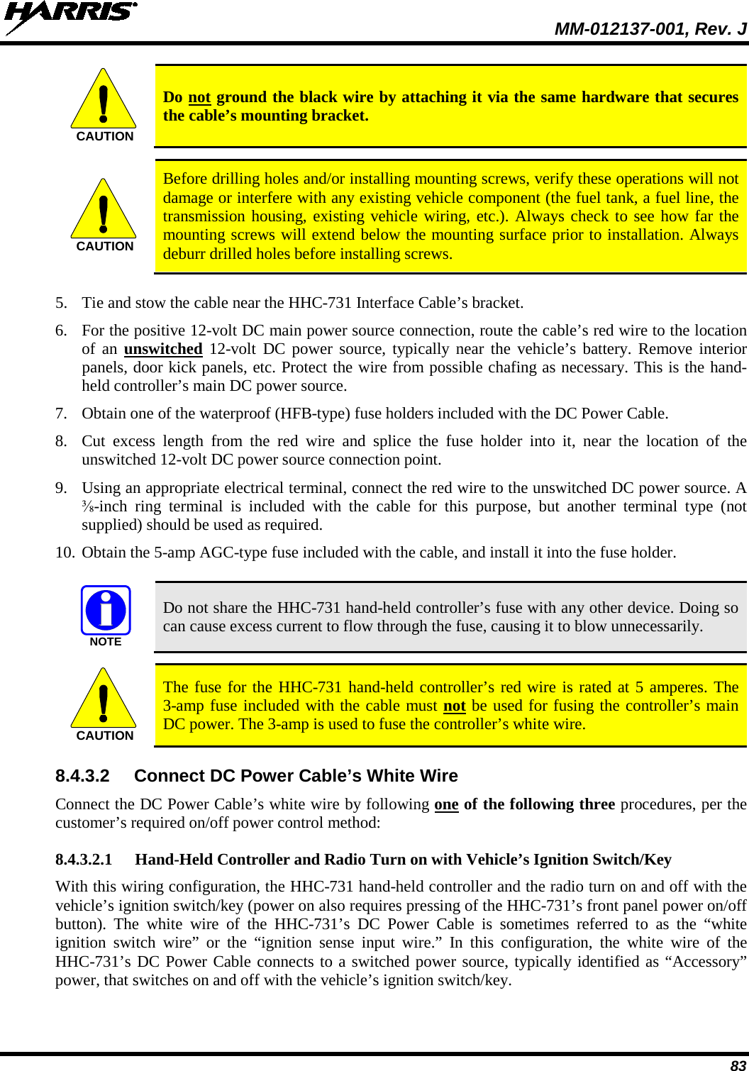
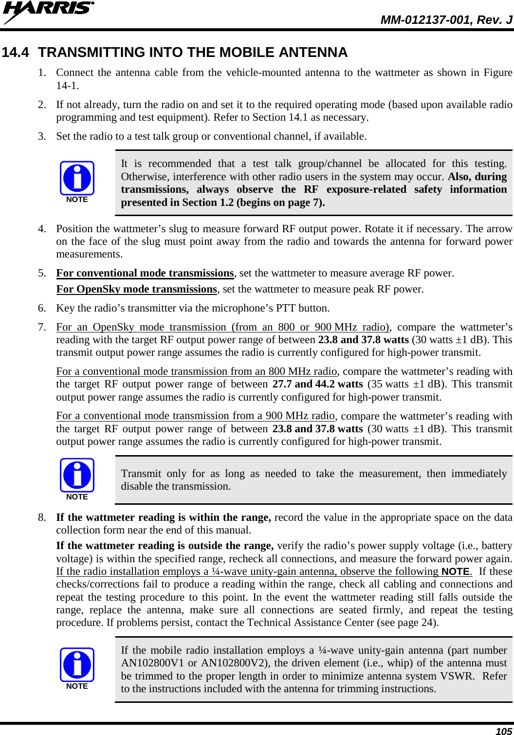
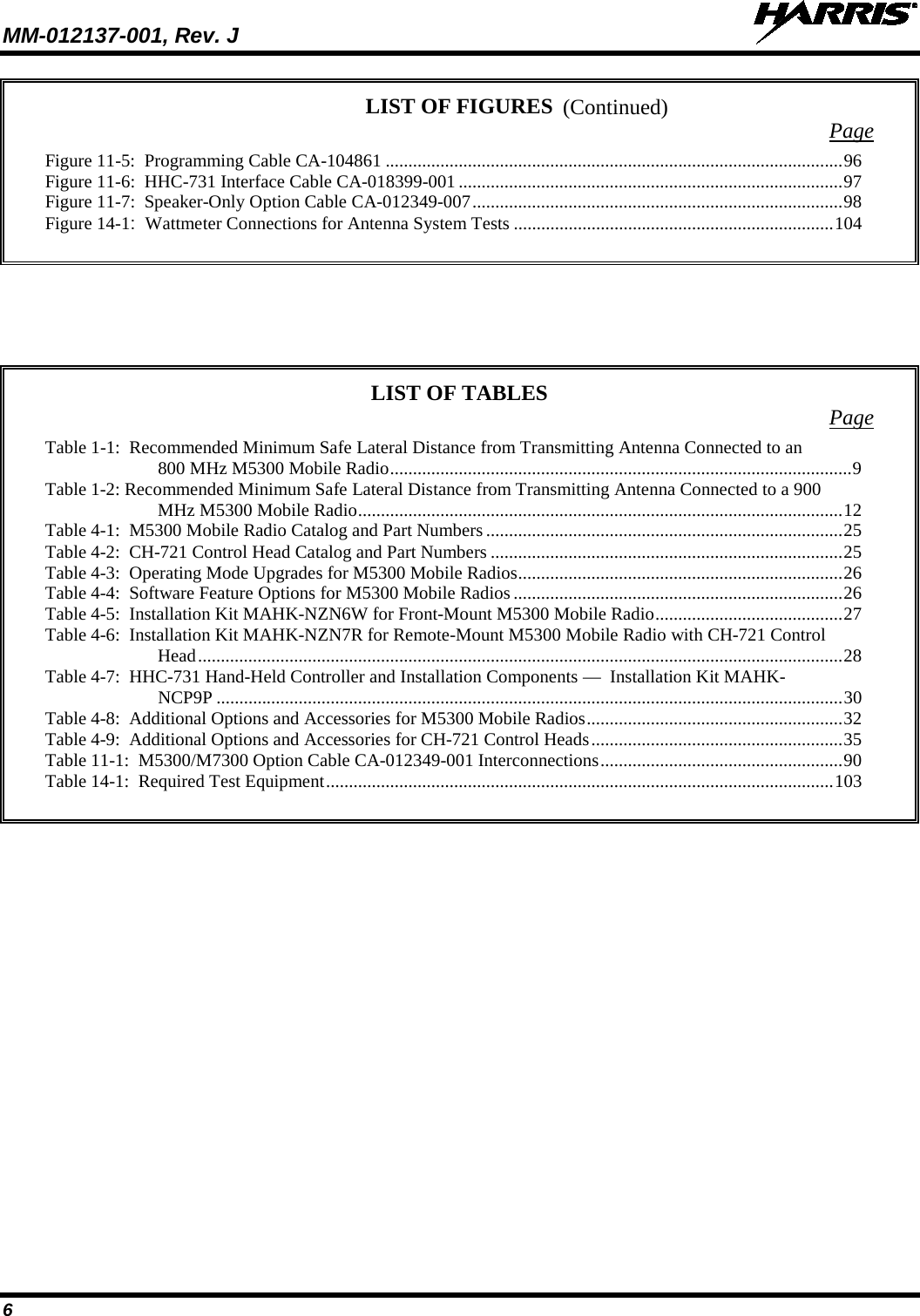
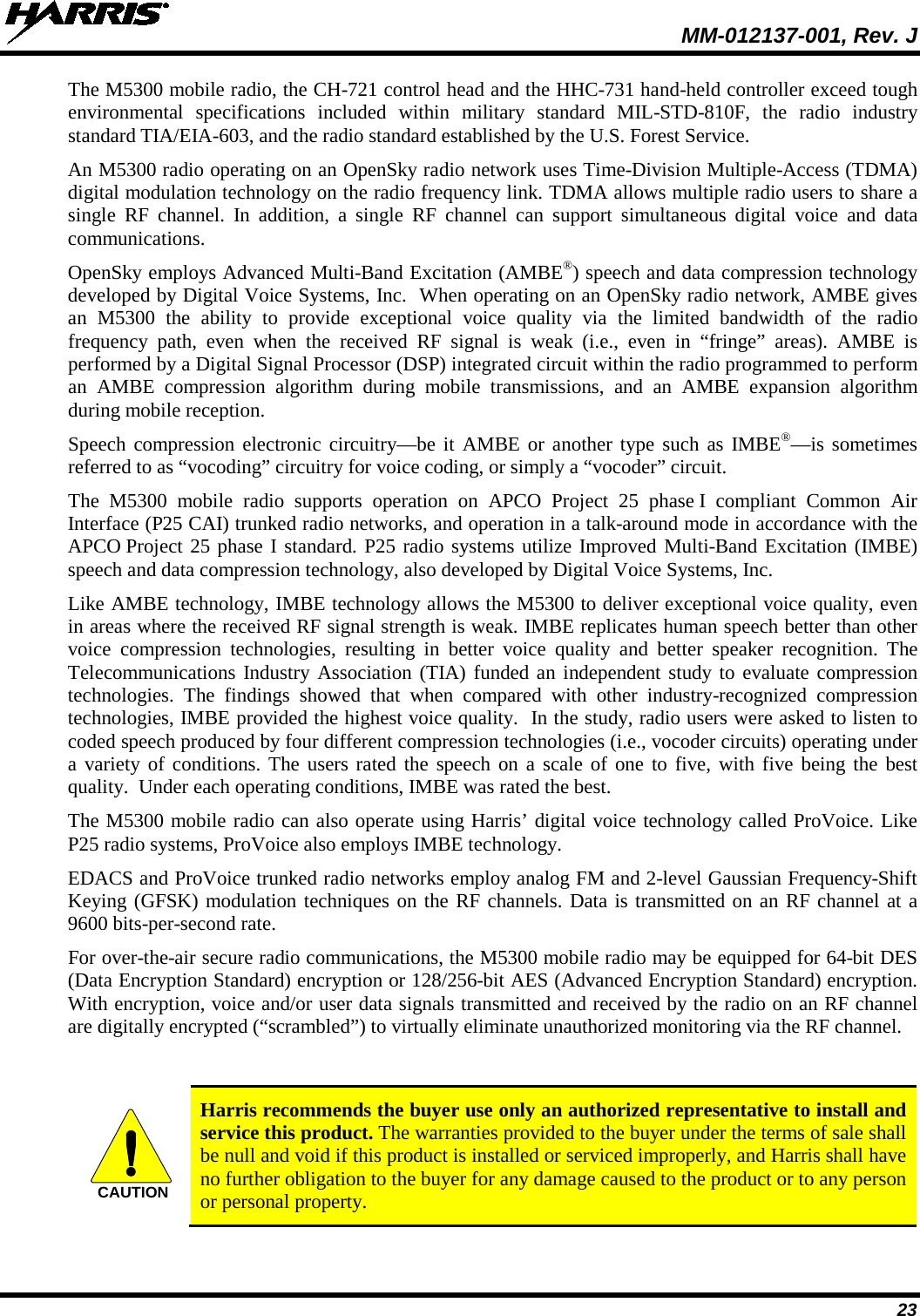
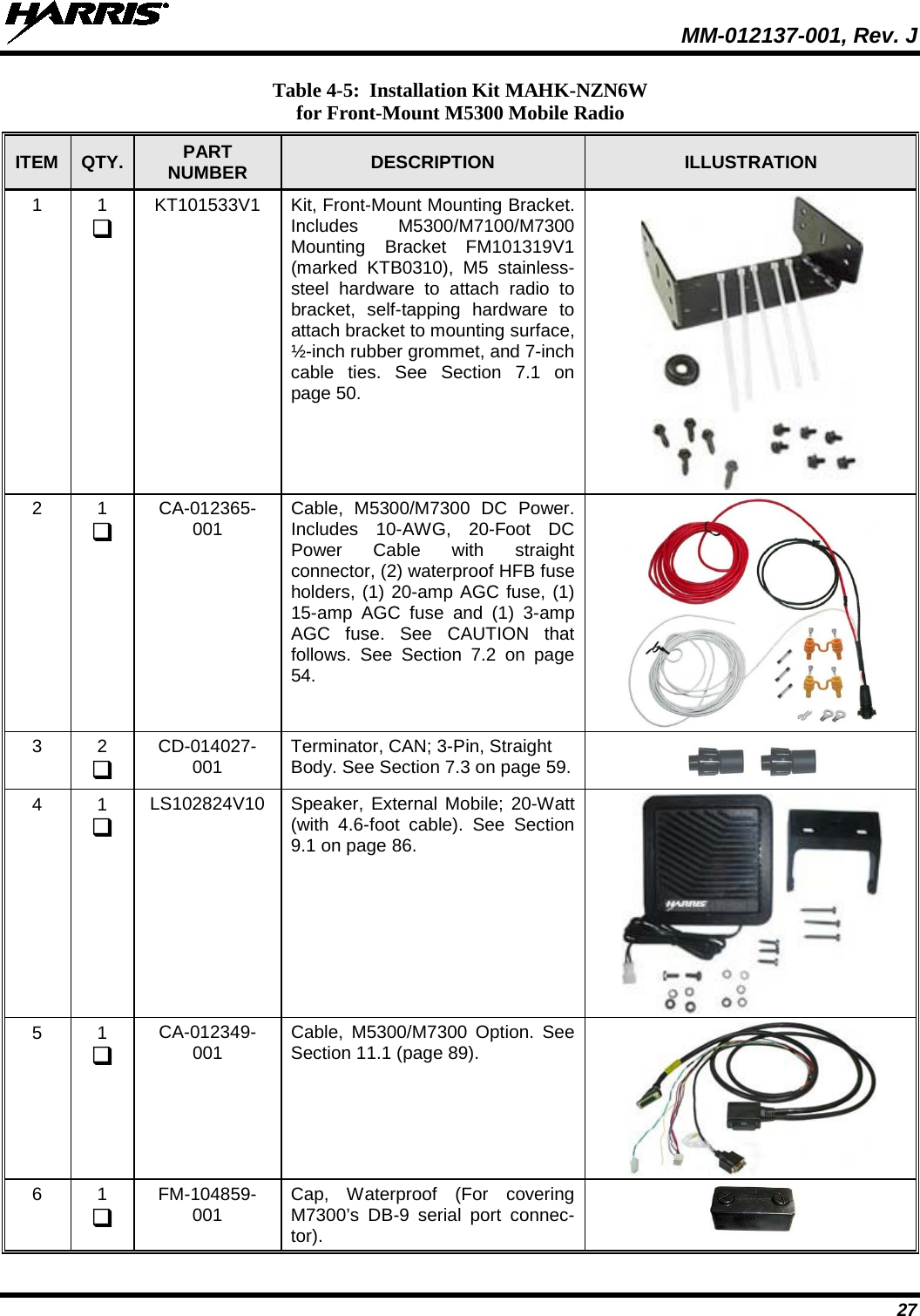
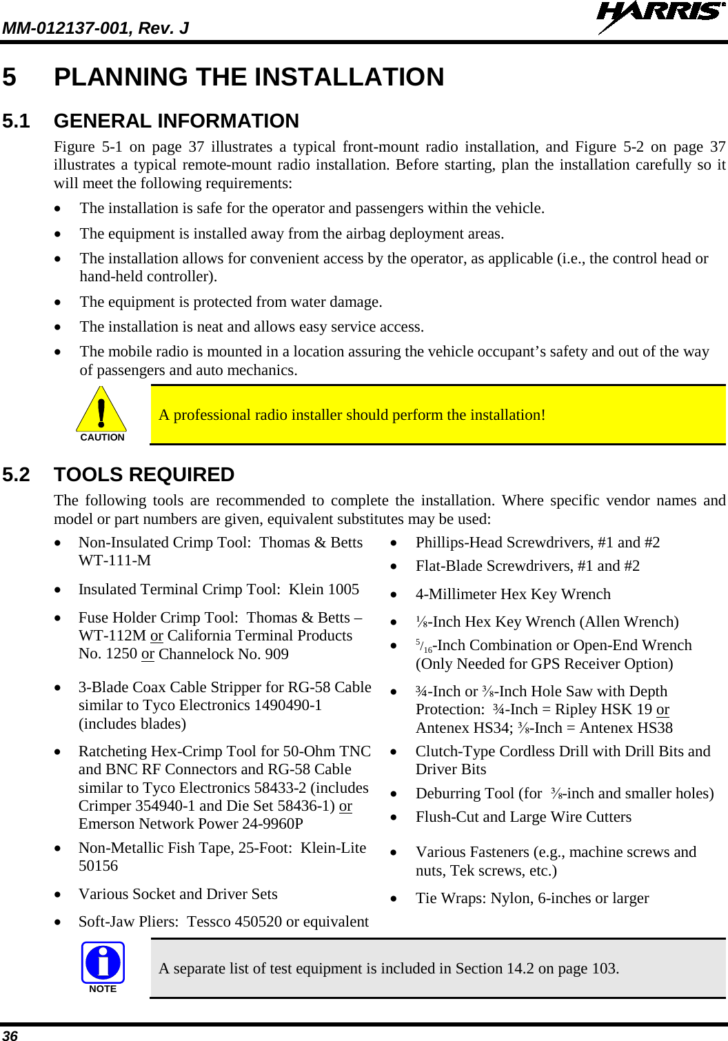
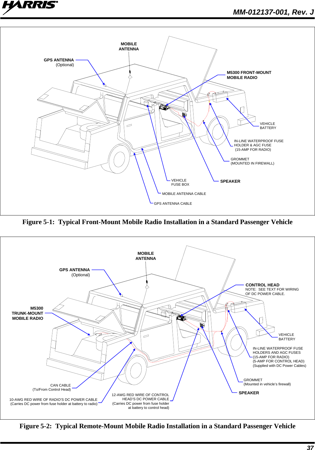
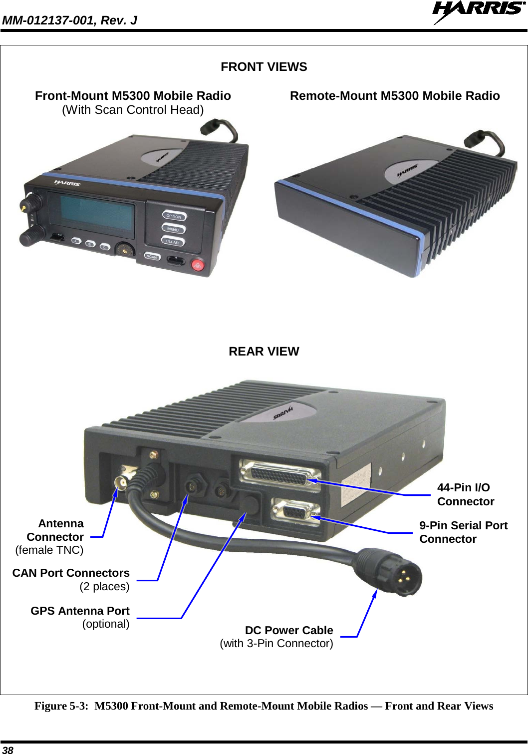
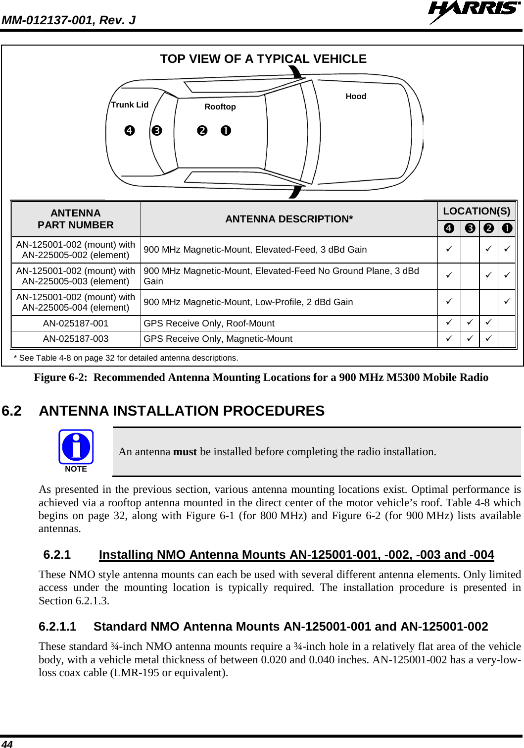
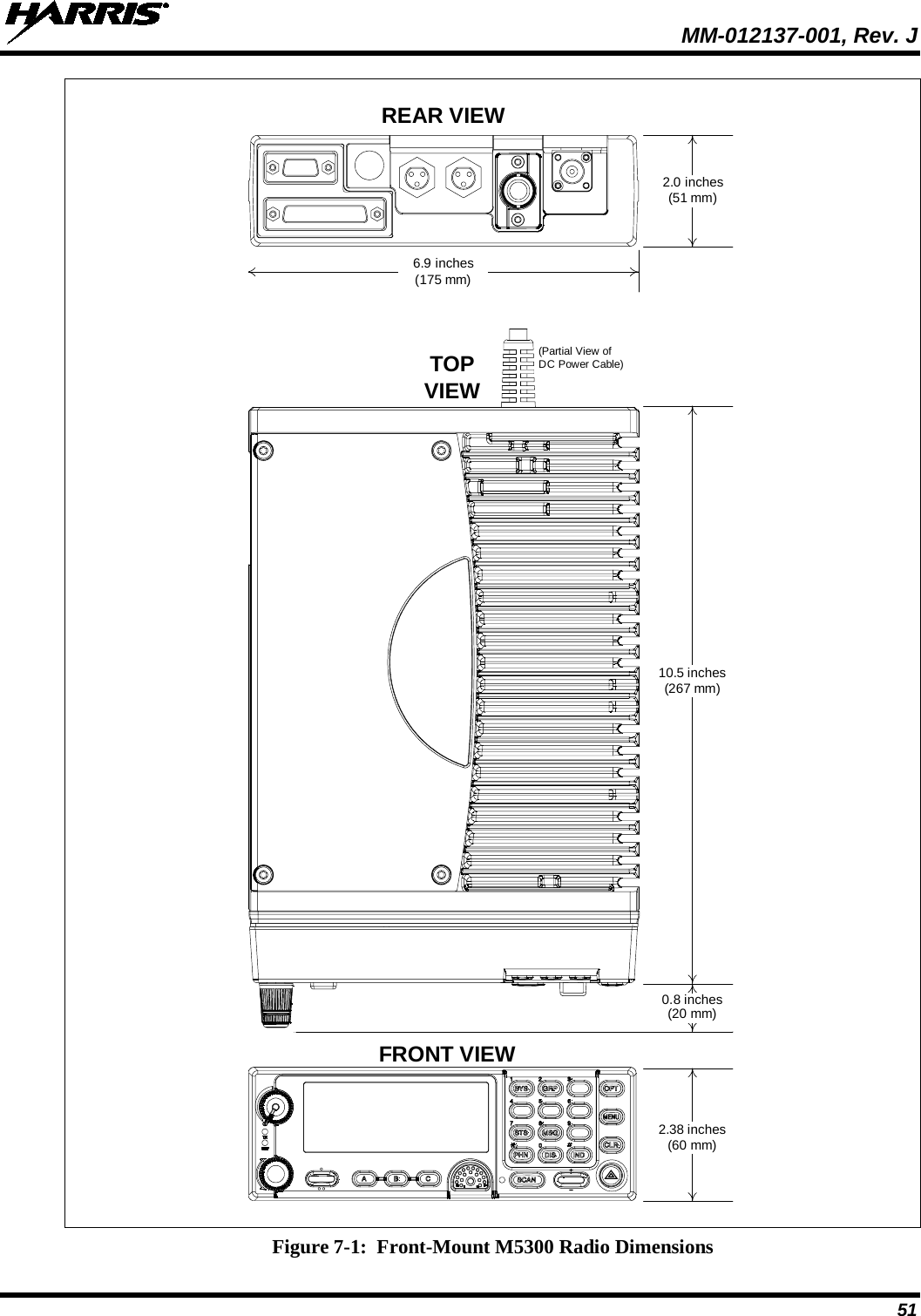
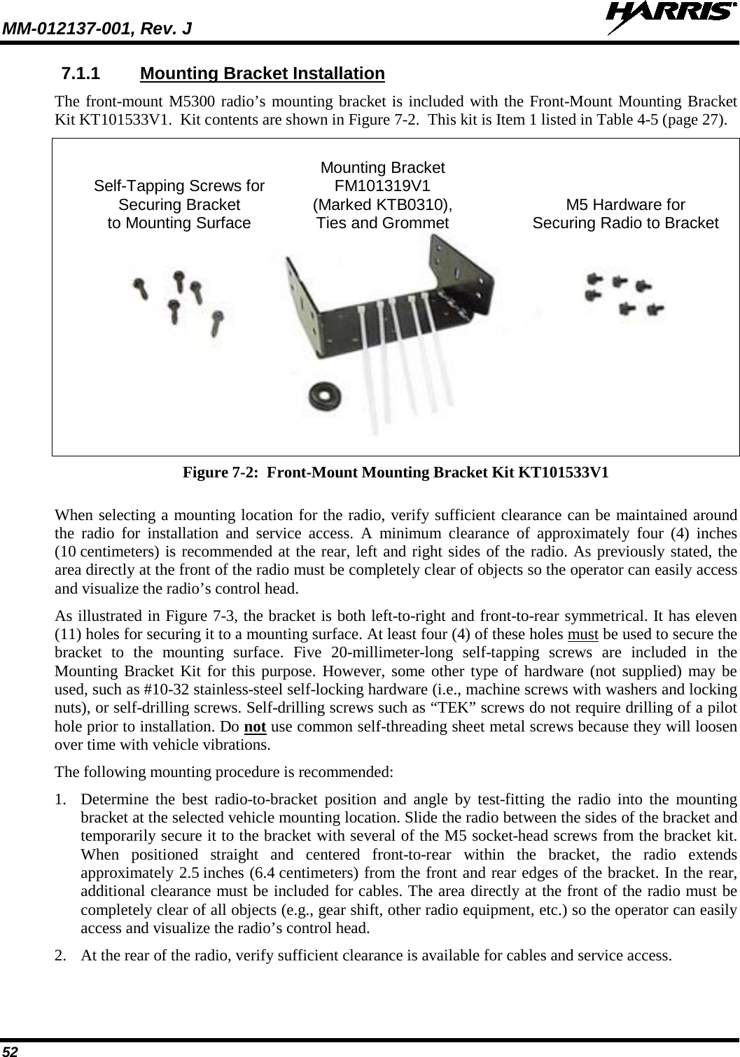
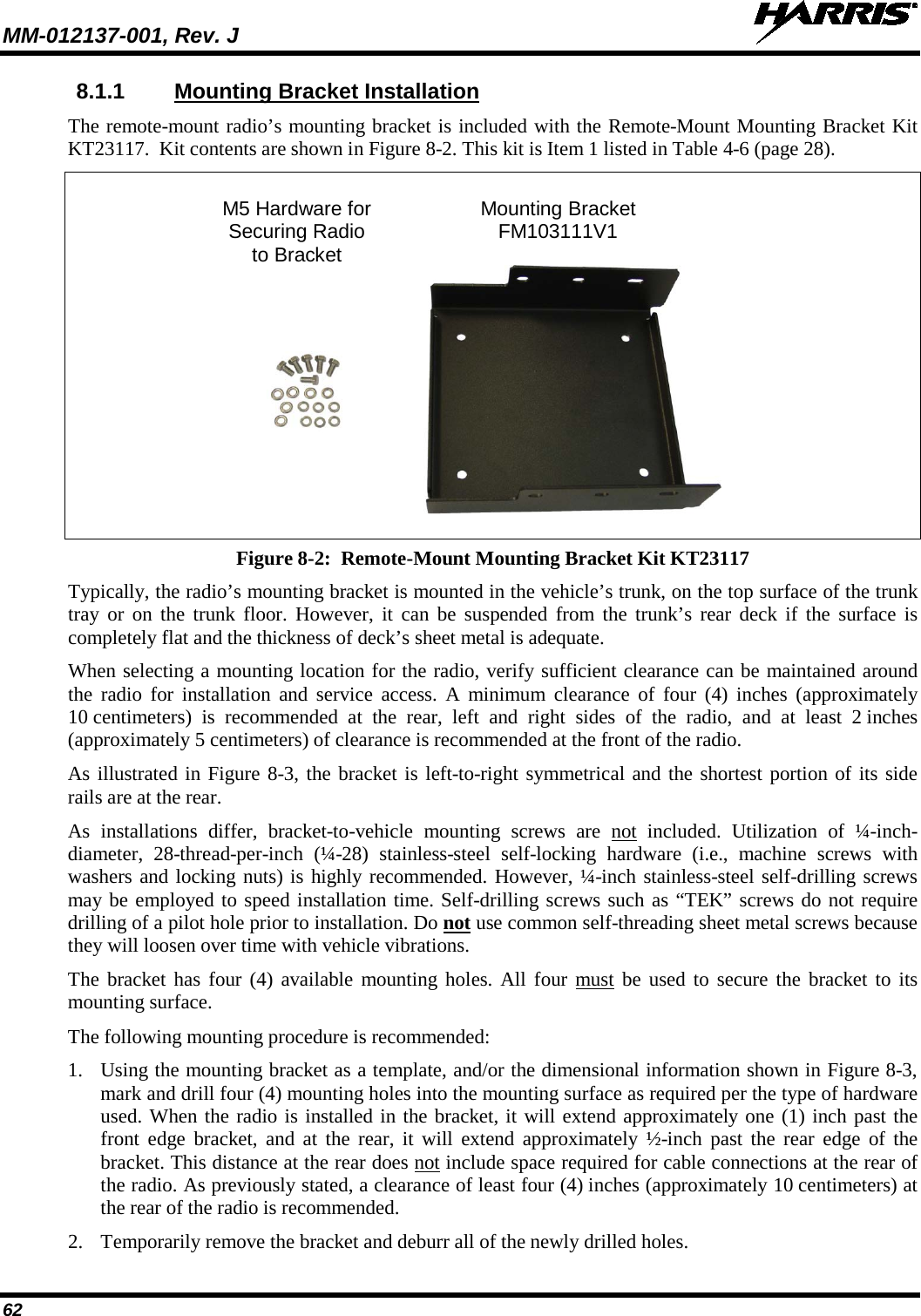
![MM-012137-001, Rev. J 5 TABLE OF CONTENTS Section Page 14.4 TRANSMITTING INTO THE MOBILE ANTENNA ...................................................................... 105 14.5 TEST PERFORMANCE DATA FORM ........................................................................................... 107 15 COMPLETE THE INSTALLATION ..................................................................................................... 108 16 WARRANTY REGISTRATION ............................................................................................................. 108 17 WARRANTY ............................................................................................................................................. 109 LIST OF FIGURES Page Figure 5-1: Typical Front-Mount Mobile Radio Installation in a Standard Passenger Vehicle .......................... 37 Figure 5-2: Typical Remote-Mount Mobile Radio Installation in a Standard Passenger Vehicle ....................... 37 Figure 5-3: M5300 Front-Mount and Remote-Mount Mobile Radios — Front and Rear Views ........................ 38 Figure 6-1: Recommended Antenna Mounting Locations for an 800 MHz M5300 Mobile Radio ..................... 42 Figure 6-2: Recommended Antenna Mounting Locations for a 900 MHz M5300 Mobile Radio ....................... 44 Figure 6-3: Installing a Standard ¾-Inch NMO Antenna Mount (e.g., AN-125001-001 or AN-125001-002) ... 46 Figure 6-4: Installing a Thick-Roof NMO Antenna Mount (e.g., AN-125001-003 or AN-125001-004) ........... 47 Figure 6-5: Crimping Instructions for TNC RF Connector ................................................................................. 48 Figure 7-1: Front-Mount M5300 Radio Dimensions ........................................................................................... 51 Figure 7-2: Front-Mount Mounting Bracket Kit KT101533V1 .......................................................................... 52 Figure 7-3: Mounting Bracket FM101319V1 (Marked KTB0310) Dimensions [for Front-Mount M5300 Mobile Radio (Radio Not Shown)] .............................................................................................. 53 Figure 8-1: Remote-Mount M5300 Radio Dimensions ....................................................................................... 61 Figure 8-2: Remote-Mount Mounting Bracket Kit KT23117 ............................................................................. 62 Figure 8-3: Mounting Bracket FM103111V1 Dimensions [for Remote-Mount M5300 Mobile Radio (Radio Not Shown)] ..................................................................................................................... 63 Figure 8-4: Wiring Diagram for a Remote-Mount Radio Installation ................................................................. 66 Figure 8-5: CH-721 Scan Model Control Head Front Panel ............................................................................... 70 Figure 8-6: CH-721 System Model Control Head Front Panel ........................................................................... 71 Figure 8-7: CH-721 Rear Panel (both control head models) ............................................................................... 71 Figure 8-8: Standard U-Shaped Control Head Mounting Bracket (Kit Part Number KT-008608) ..................... 72 Figure 8-9: Optional Control Head Mounting Pedestal (Part Number MACDOS0012) ..................................... 72 Figure 8-10: CAN Link Connections for a Single Control Head Installation ..................................................... 74 Figure 8-11: Typical CAN Link Connections for a Multi-Control Head Installation ......................................... 74 Figure 8-12: Contents of Vehicle Fuse and T-Tap Kit FS24473 ......................................................................... 78 Figure 8-13: Attaching T-Tap Terminals to a Switched Power Wire .................................................................. 79 Figure 8-14: HHC-731 Hand-Held Controller Front View ................................................................................. 80 Figure 8-15: HHC-731 Interface Cable Mounting Bracket Kit KT-018752-001 ................................................ 80 Figure 8-16: HHC-731 Interface Cable Mounting Bracket-to-Cable Positioning ............................................... 81 Figure 8-17: M5300-to-HHC-731 CAN Link Connections ................................................................................ 82 Figure 10-1: Attaching the Microphone to the CH-721 Control Head ................................................................ 88 Figure 11-1: M5300/M7300 Option Cable CA-012349-001 ............................................................................... 89 Figure 11-2: Serial Programming Cable CA-013671-020 ................................................................................... 93 Figure 11-3: CH-721 Option Cable CA-011854-001 .......................................................................................... 94 Figure 11-4: Accessory Cable 19B802554P24.................................................................................................... 95 (Continued)](https://usermanual.wiki/HARRIS/TR-0049-E.Install-Manual/User-Guide-1331924-Page-5.png)
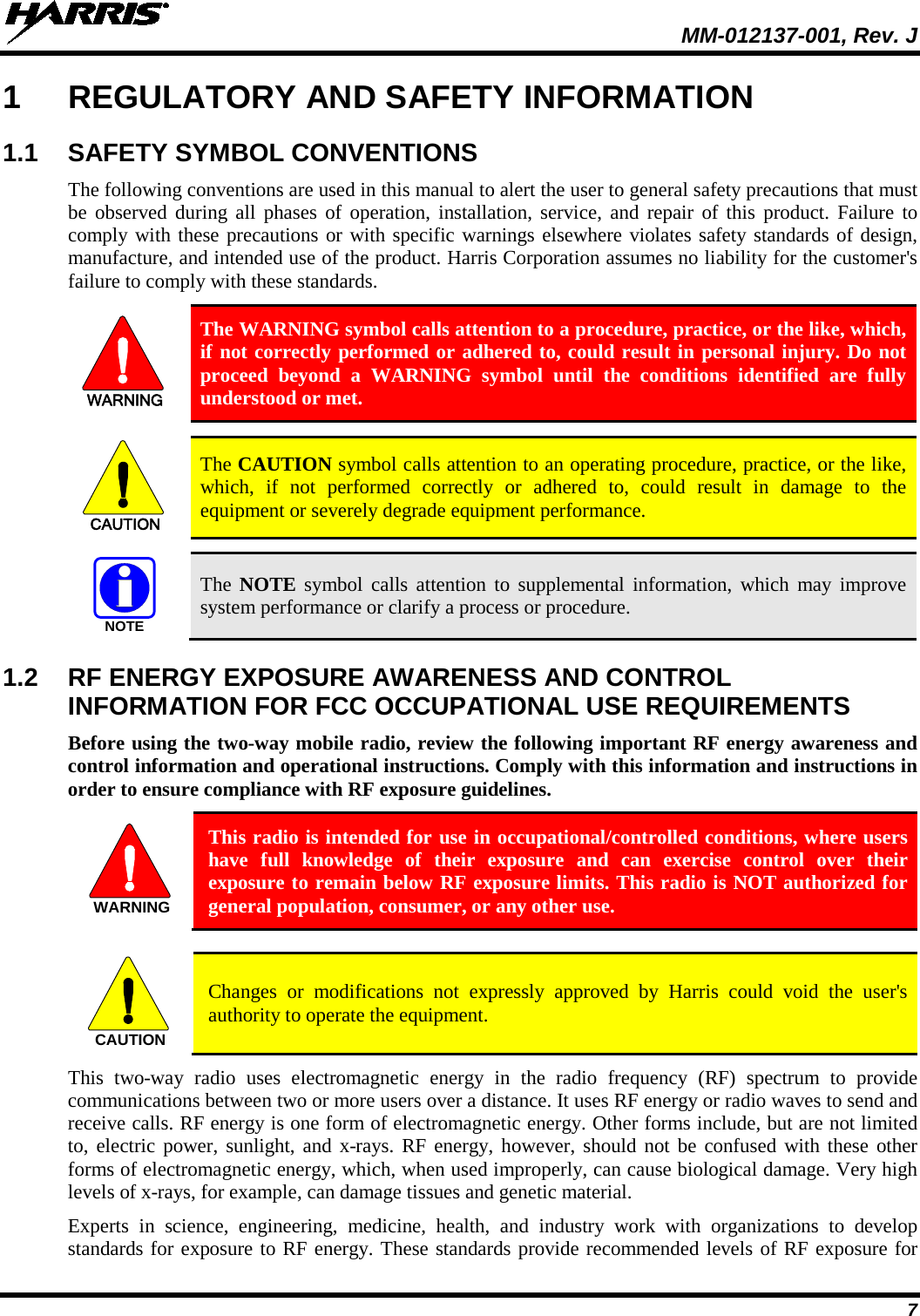
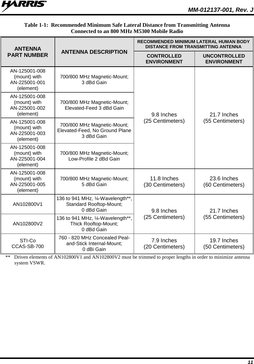
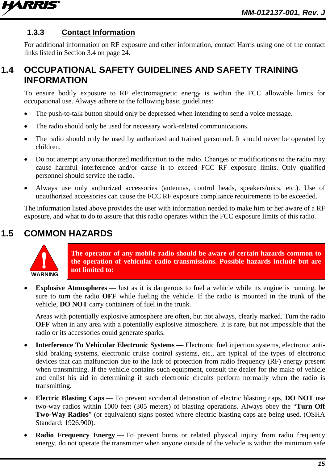

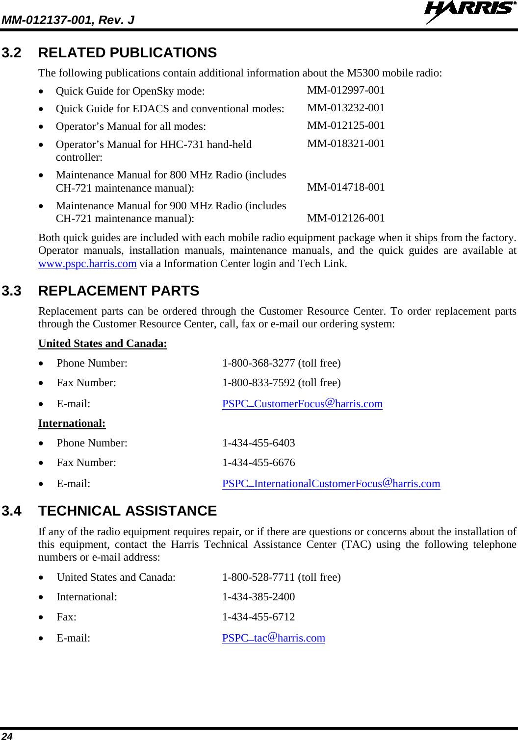
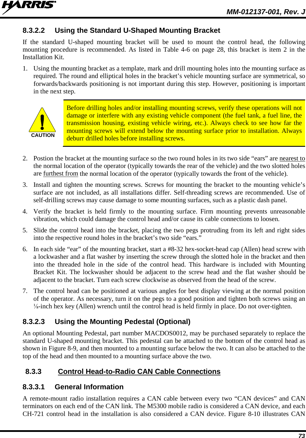
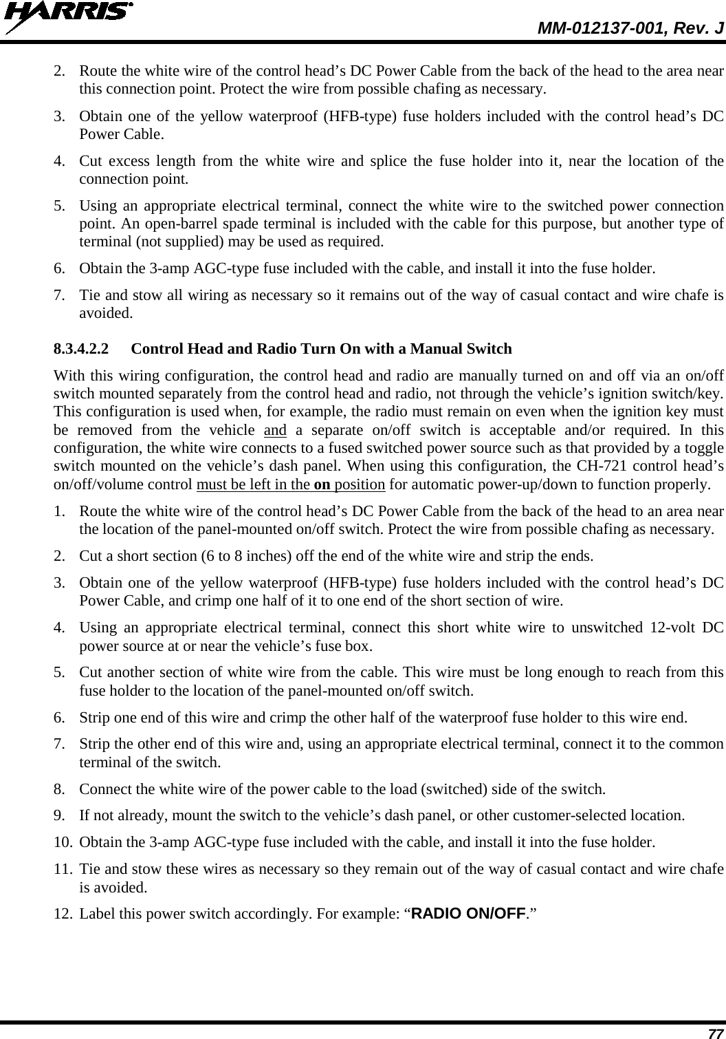
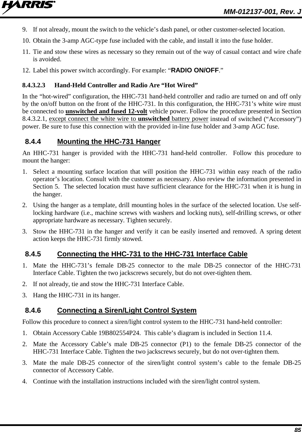
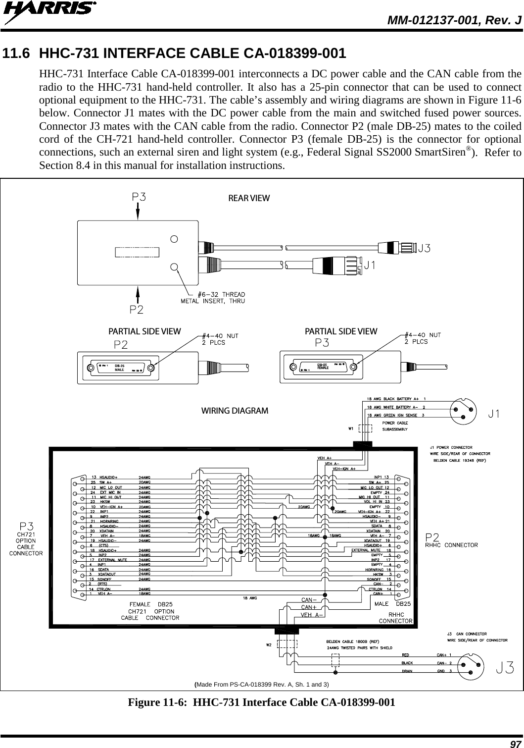
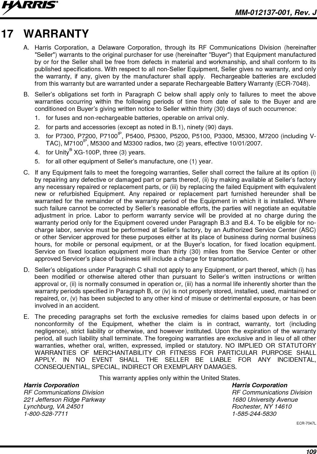
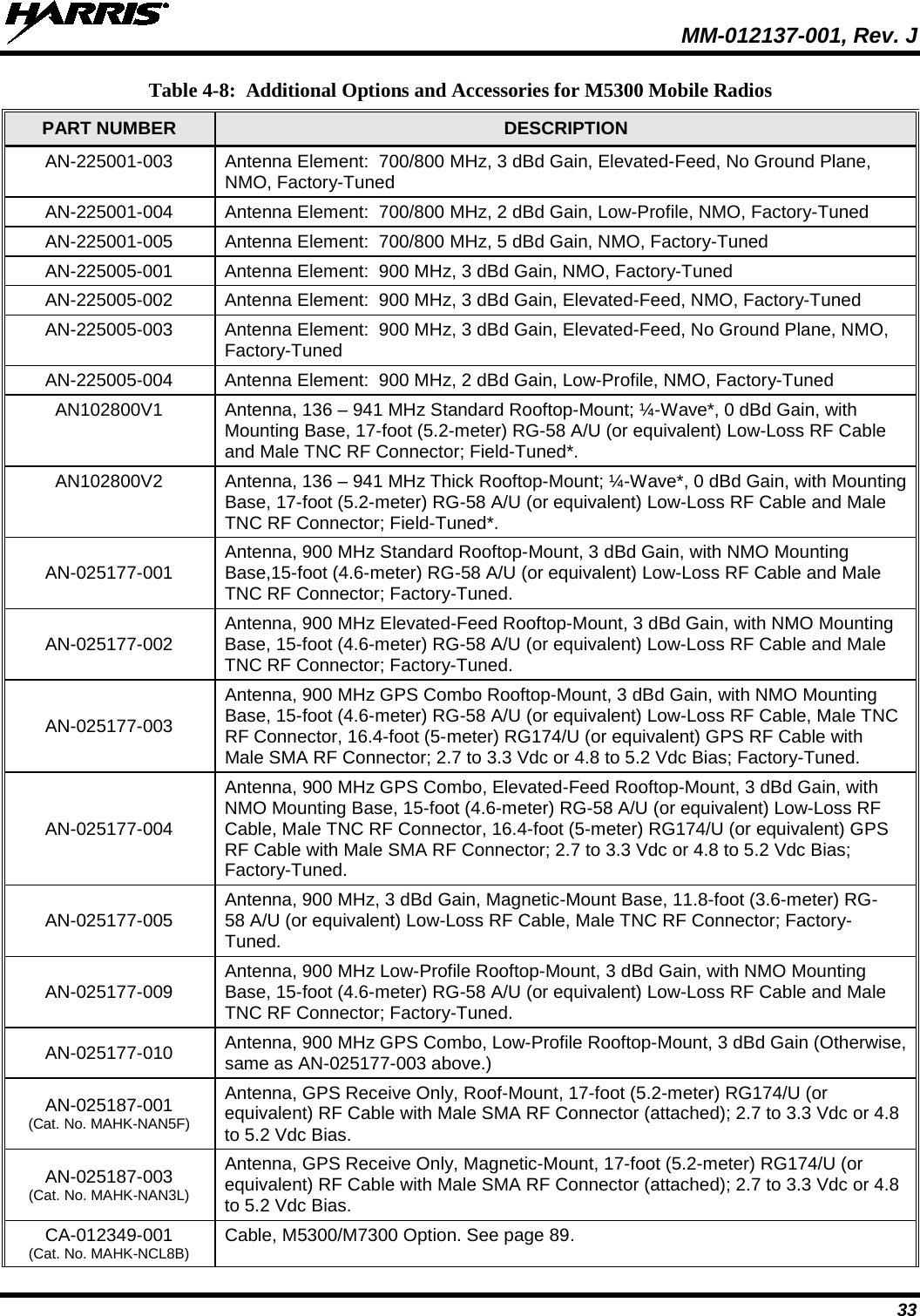
![MM-012137-001, Rev. J 29 Table 4-6: Installation Kit MAHK-NZN7R for Remote-Mount M5300 Mobile Radio with CH-721 Control Head ITEM QTY. PART NUMBER DESCRIPTION ILLUSTRATION 6 1 CA-009562-030 Cable, CAN; 30 feet, Right-Angle-to-Straight Connectors. See Sec-tion 8.3.3 on page 73 7 1 LS102824V10 Speaker, External Mobile; 20-Watt (with 4.6-foot cable). See Section 9.2 on page 86. 8 1 MAMROS0034-NN006 Cable, Speaker; 6-Inch, Straight Connector. Section 9.2 on page 86. 9 2 FM-104859-001 Cap, Waterproof (For covering DB-9 serial port connectors on radio and control head.) [See footnote 2] 10 2 FM-104859-002 Cap, Waterproof (For covering DB-25 connectors on radio and control head.) [See footnote 2] The 20-amp fuse included with DC Power Cable CA-012365-001 should not be used in the M5300 mobile radio application of this cable. M5300 radio main power should be protected with the 15-amp fuse. Refer to Section 13 for additional information. 2 Earlier installation kits contained only one (1) each of FM-104859-001 and FM-104859-002. CAUTION(Continued)](https://usermanual.wiki/HARRIS/TR-0049-E.Install-Manual/User-Guide-1331924-Page-29.png)
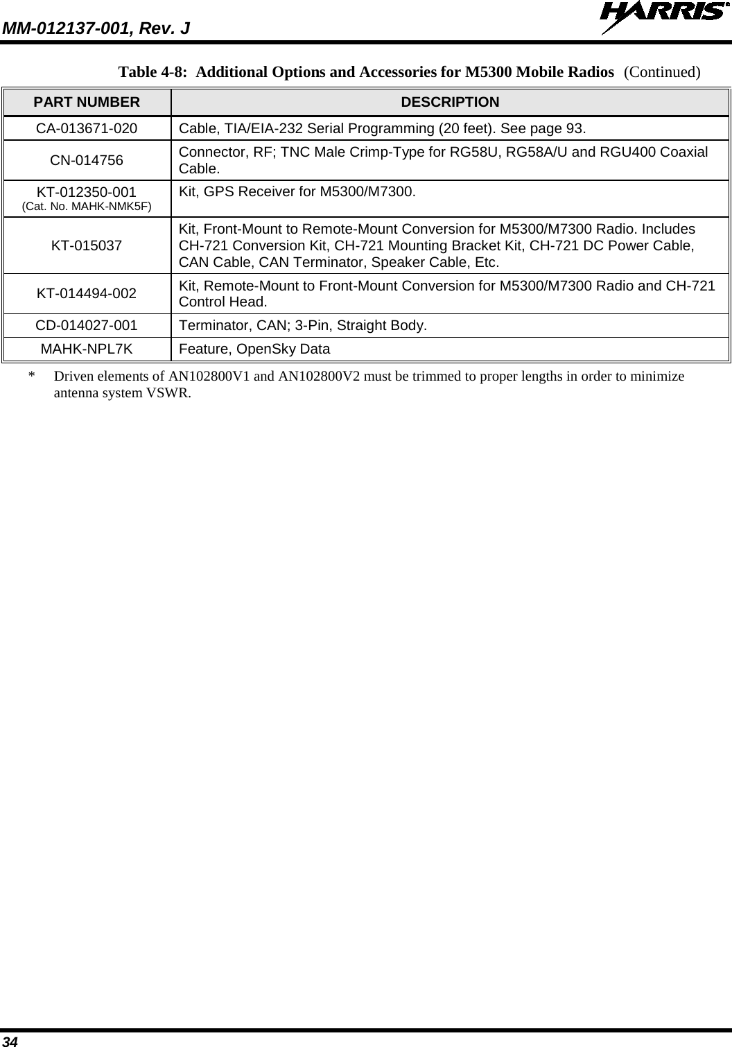
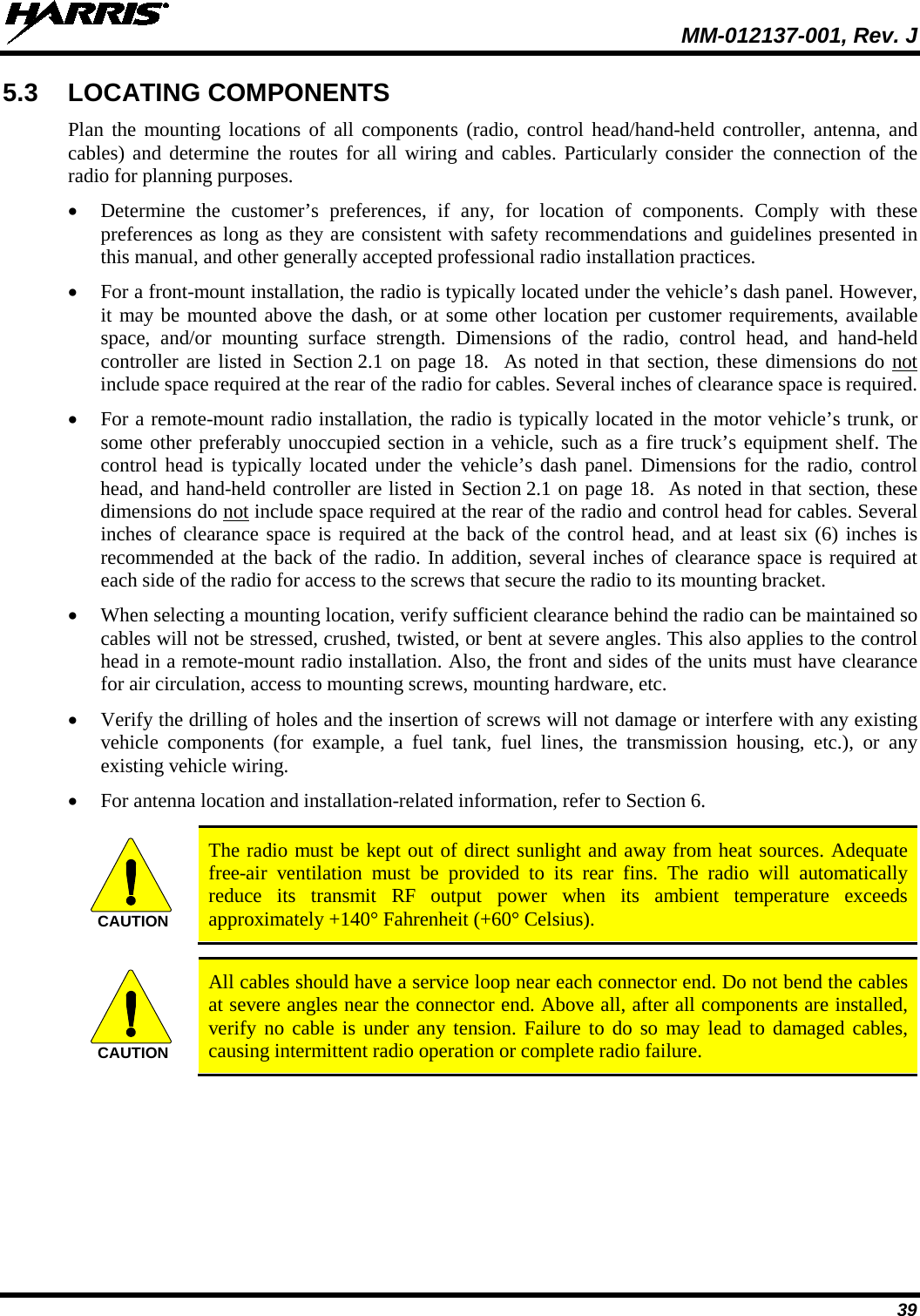
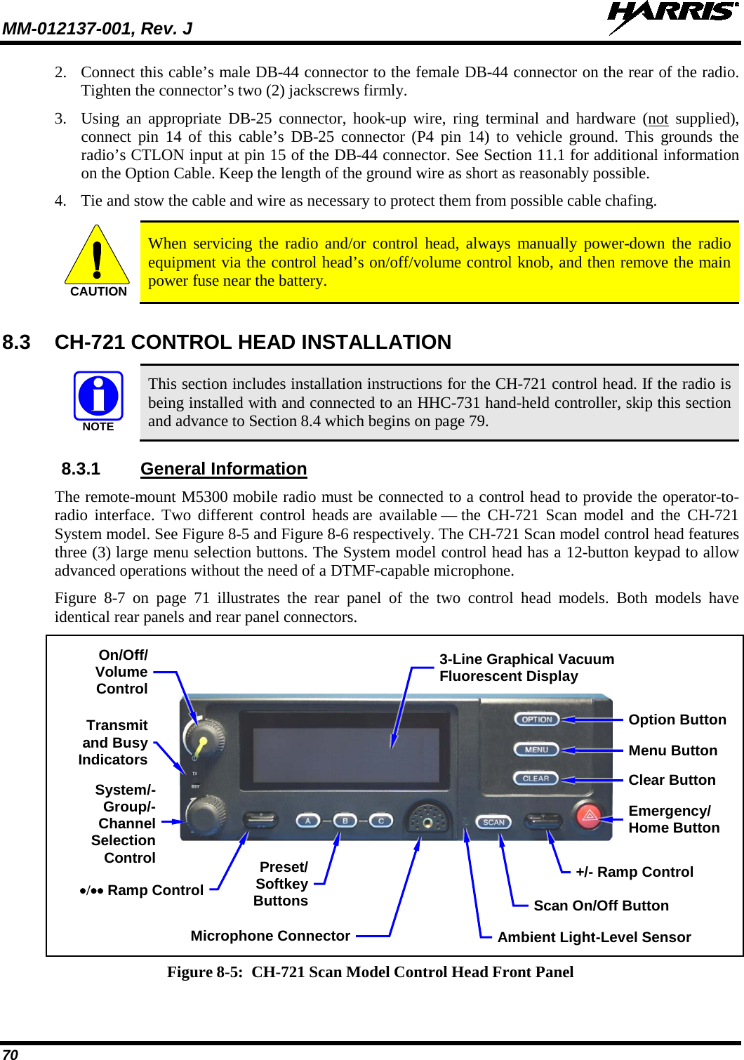
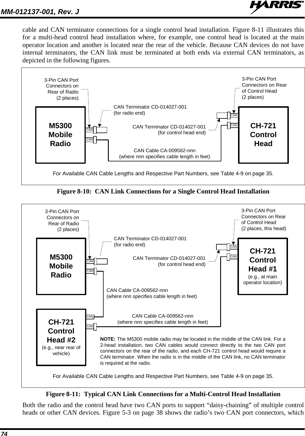
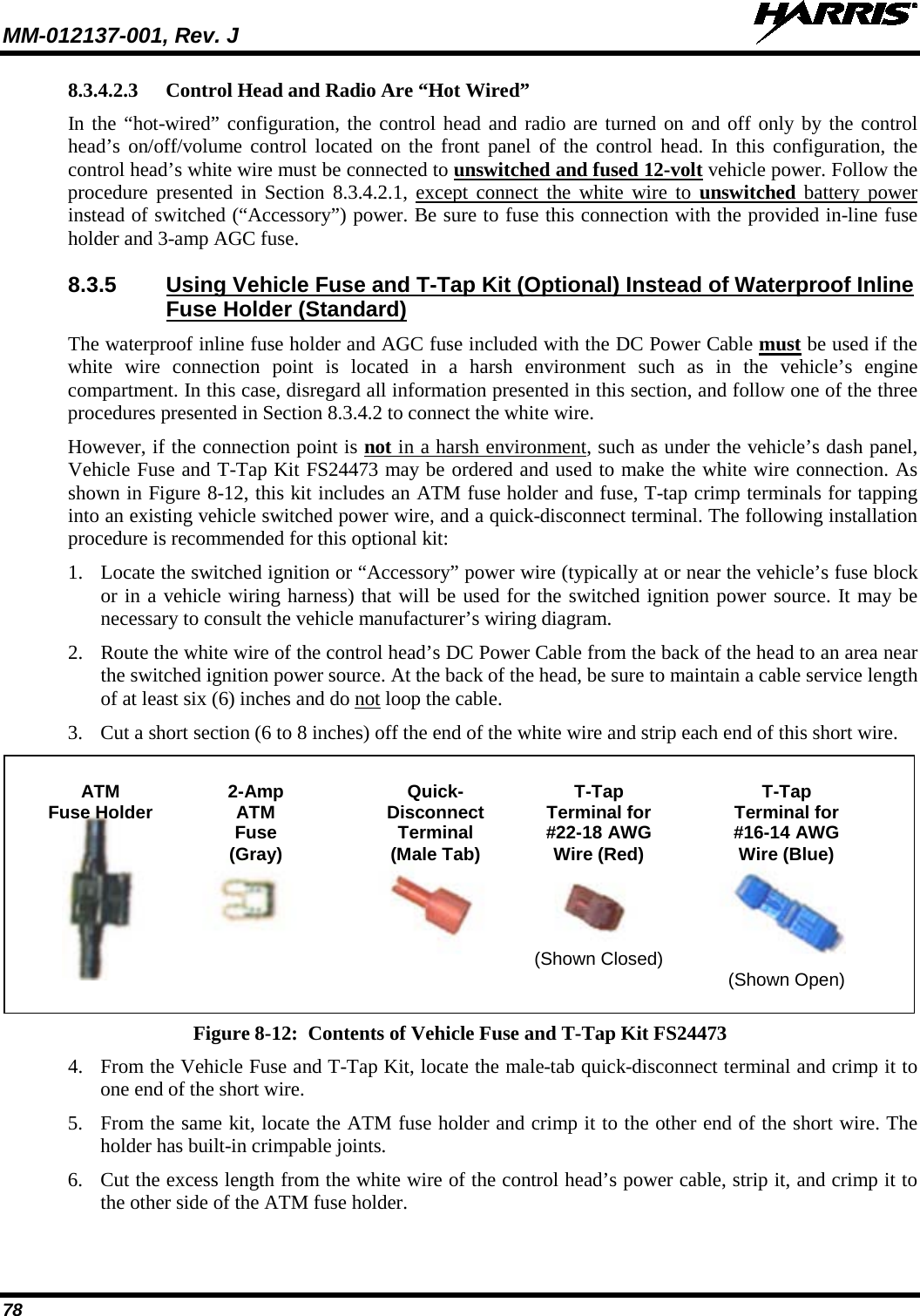
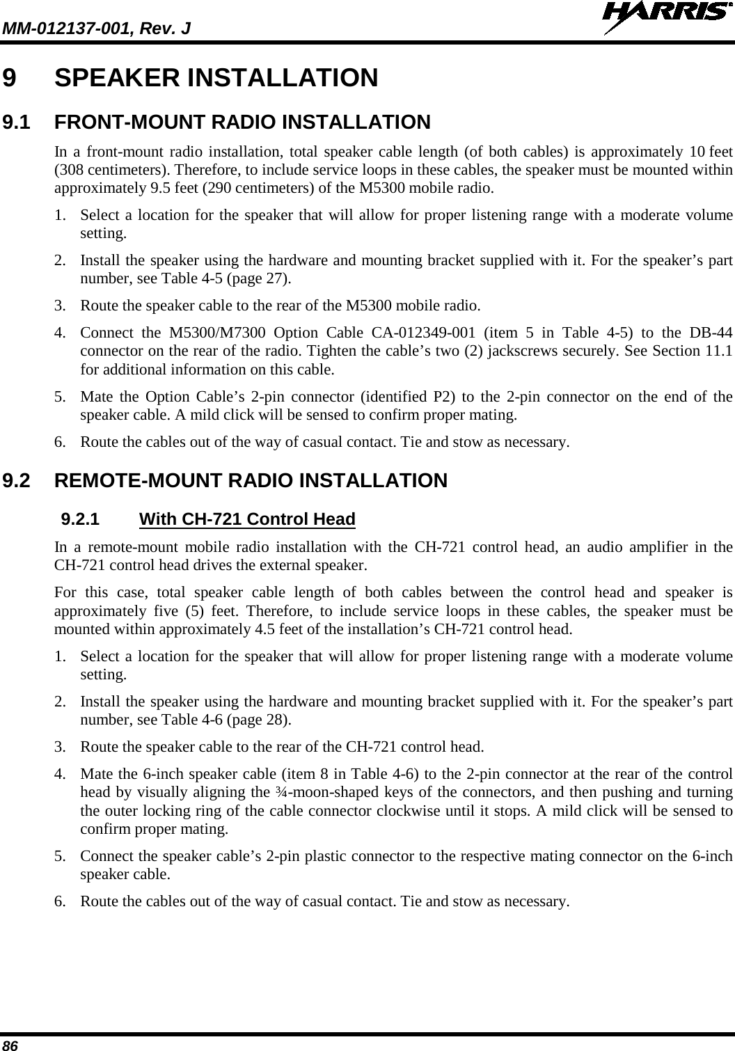
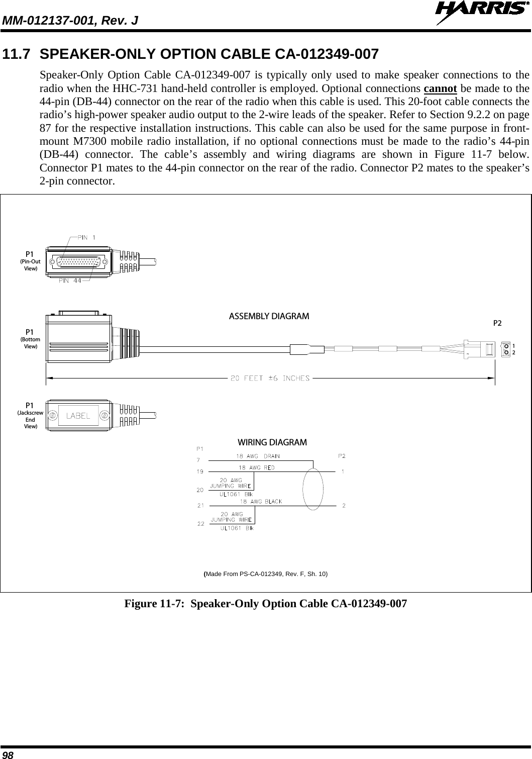
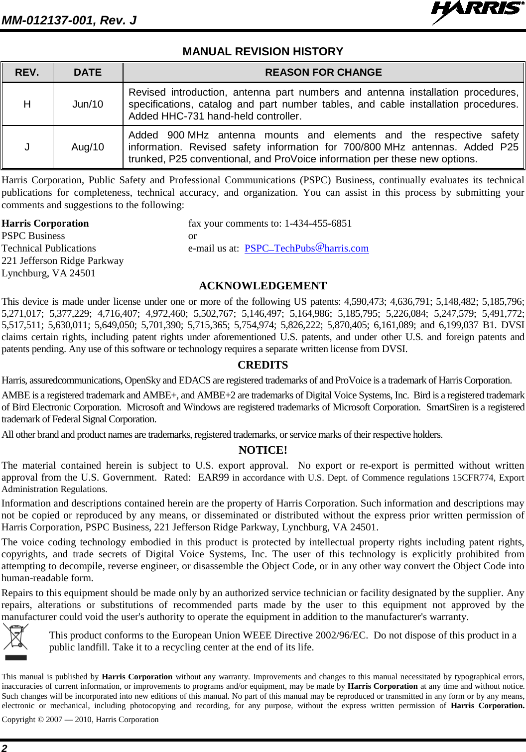
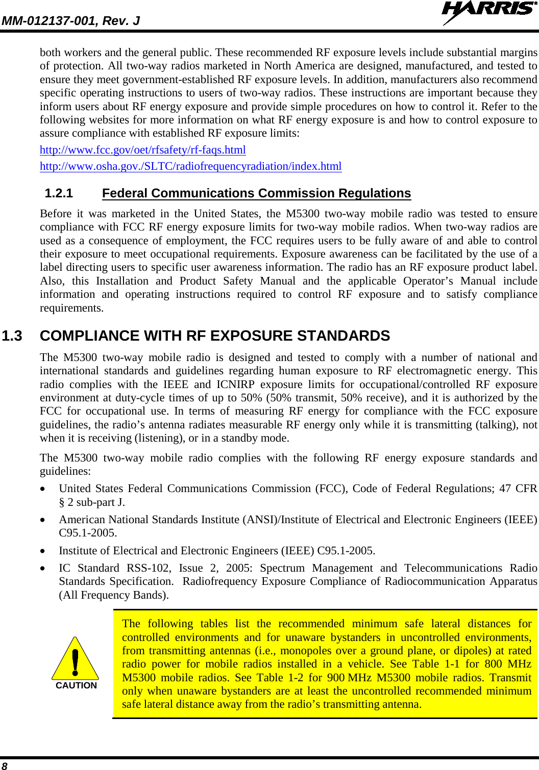
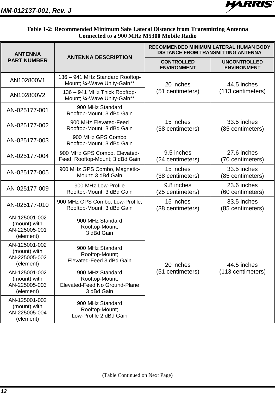
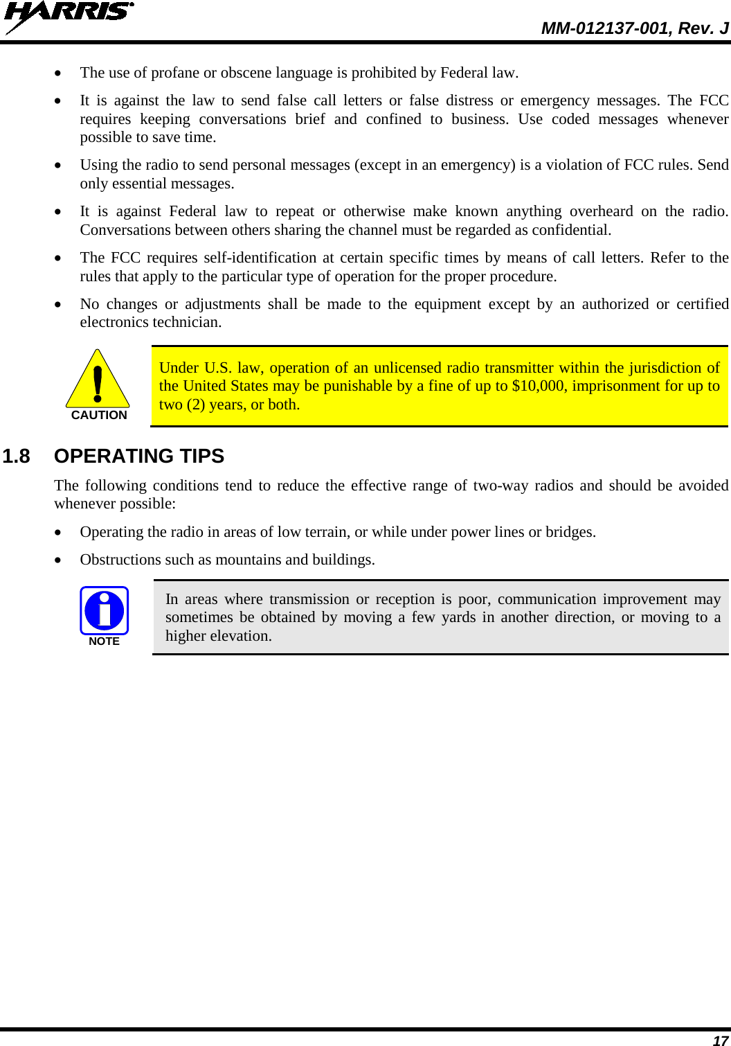
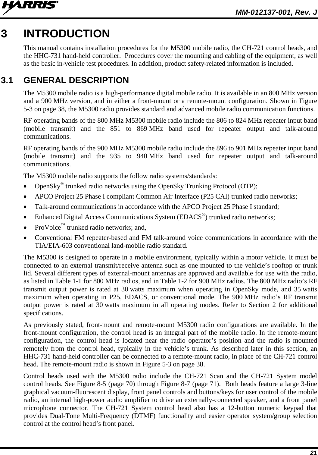
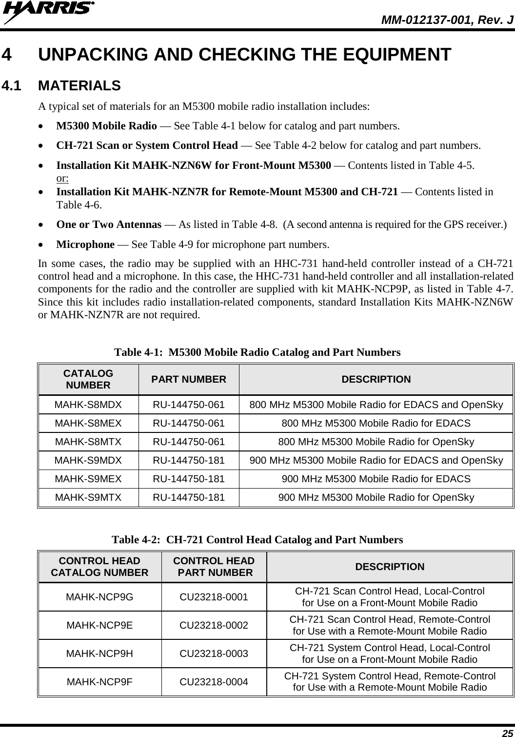
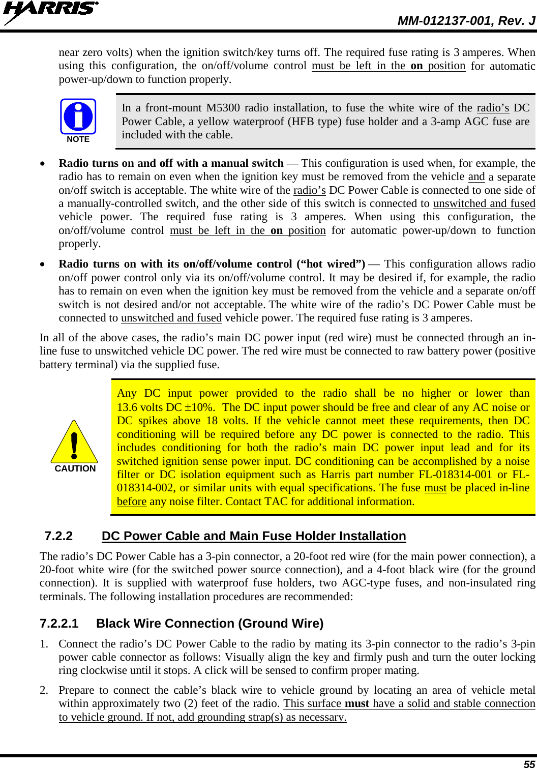
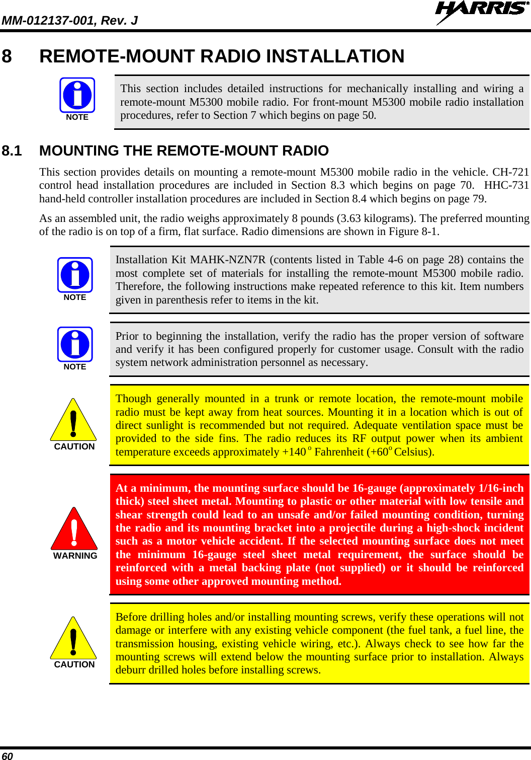
![MM-012137-001, Rev. J 53 TOP VIEW SIDE VIEW (Dimensions in Inches) FRONT/REAR VIEW (Dimensions in Inches) (Made From KBT0310B) Figure 7-3: Mounting Bracket FM101319V1 (Marked KTB0310) Dimensions [for Front-Mount M5300 Mobile Radio (Radio Not Shown)] 3. If the mounting surface is not flat (such as the top of a transmission hump), construct a suitable mounting wedge as necessary, and attach the wedge to the surface using an approved attachment method. Never mount the bracket directly to a non-flat surface. 4. On the mounting surface, mark the selected location for the bracket, and then remove the radio from the bracket. 5. Clean and remove any foreign material from the mounting surface. 6. Using the bracket as a template, and/or the dimensional information shown in Figure 8-3, mark and drill at least four (4) mounting holes into the mounting surface as required per the type of hardware used. 5.160.83 1.81 3.59 5.36 6.341.591.952.58(FM101319V1)B3.563.207.172.68Bracket-To-Vehicle Screw Holes (11 places) Bracket-To-Radio Screw Holes (10 places,5 each side)](https://usermanual.wiki/HARRIS/TR-0049-E.Install-Manual/User-Guide-1331924-Page-53.png)

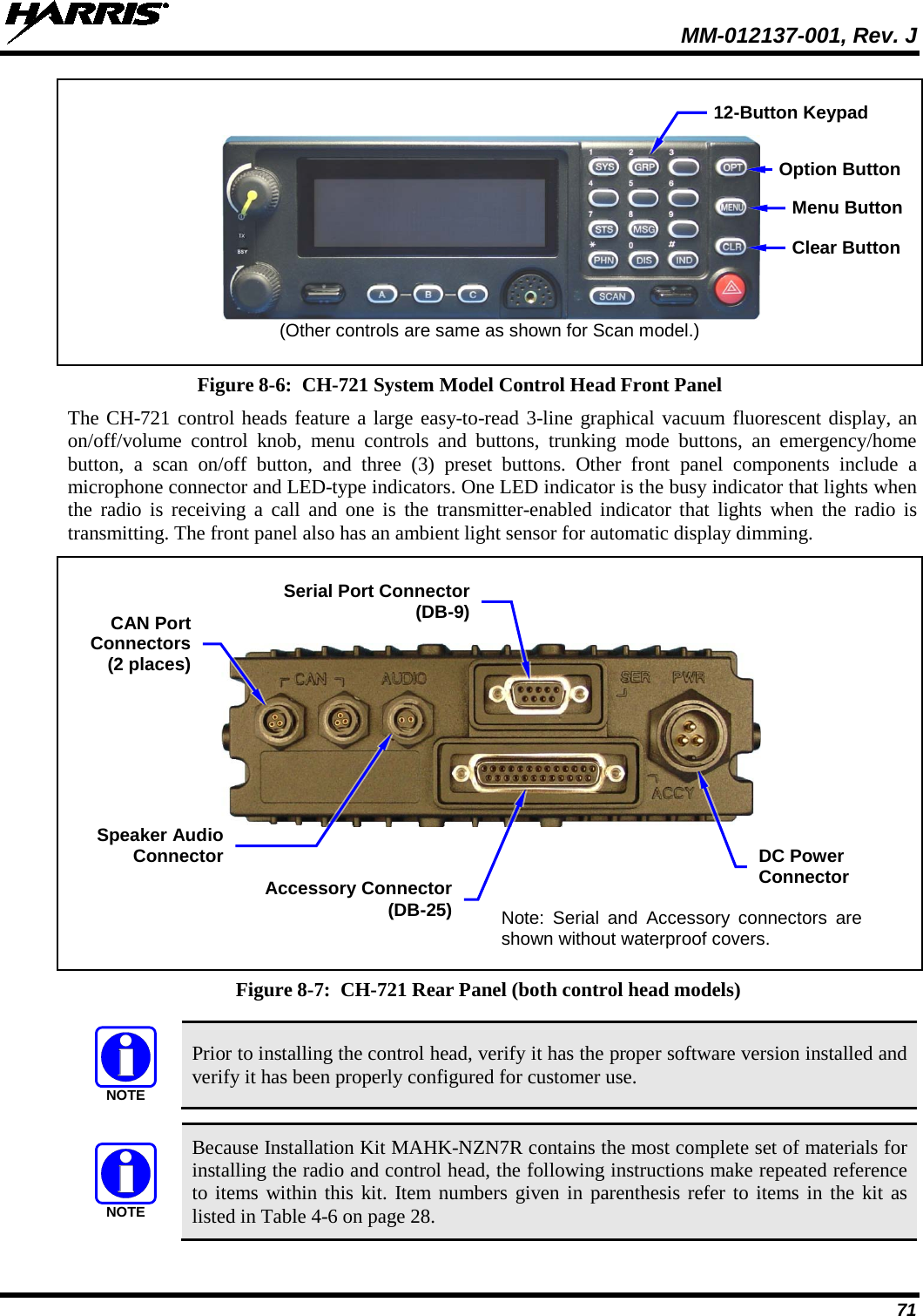
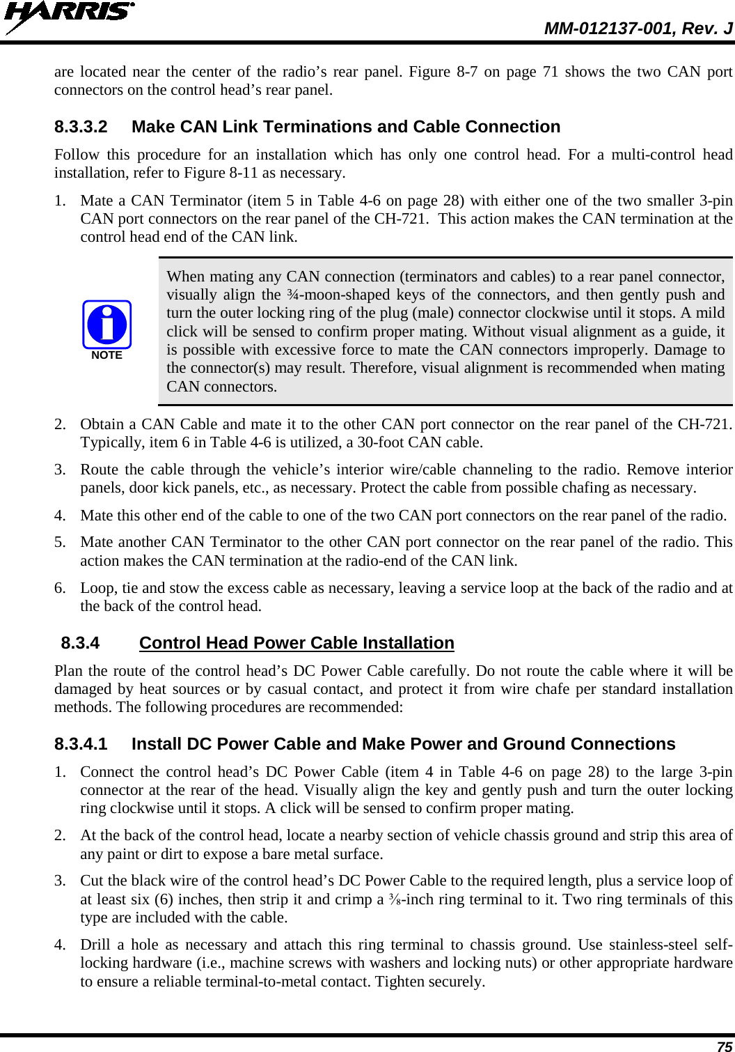
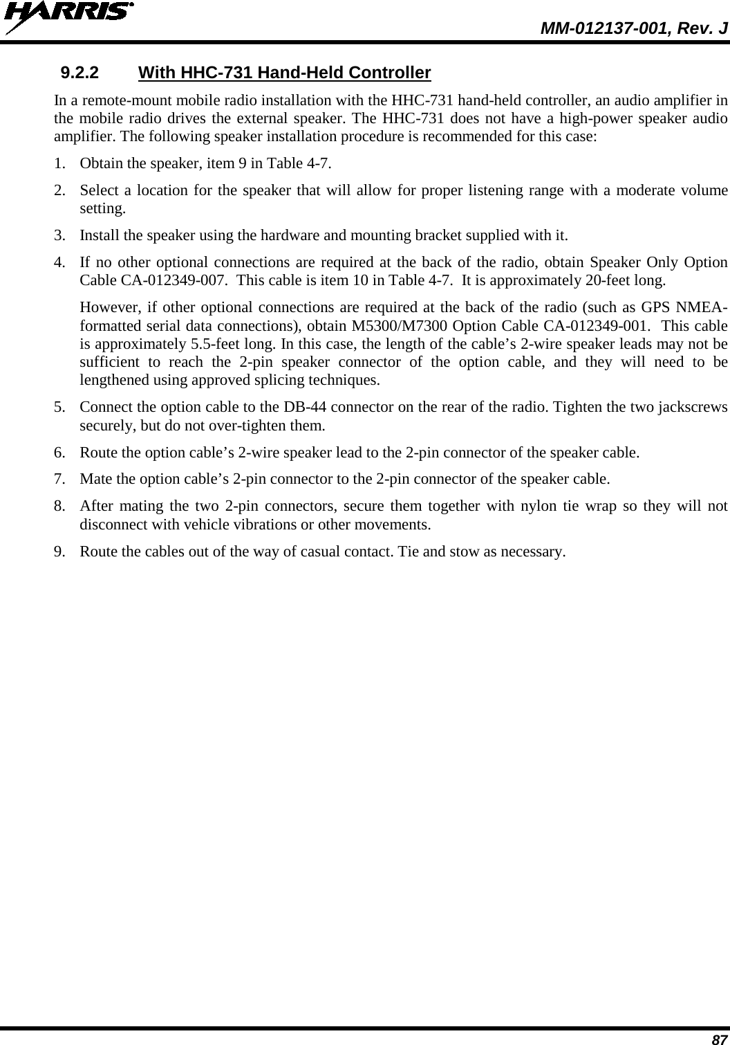
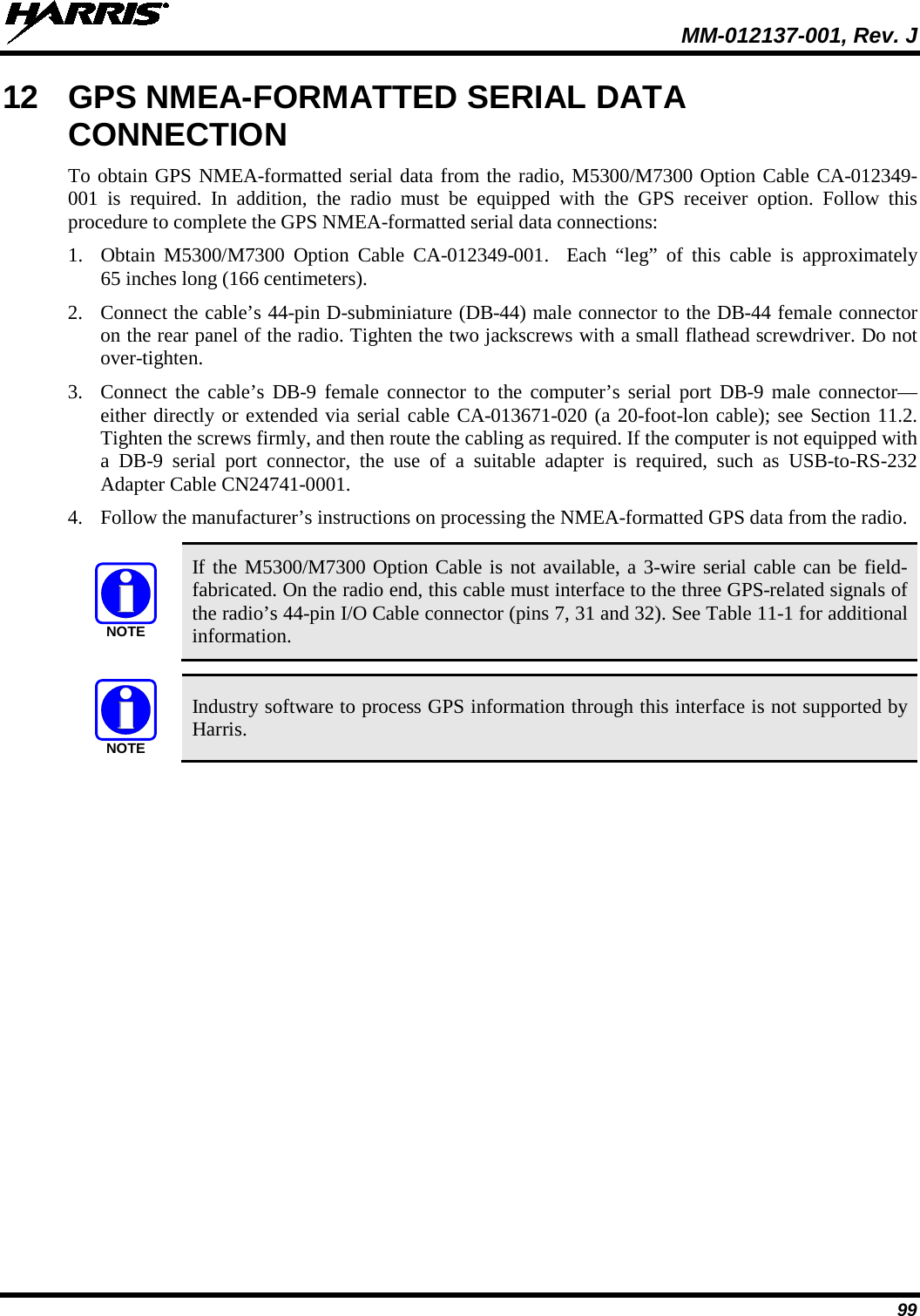
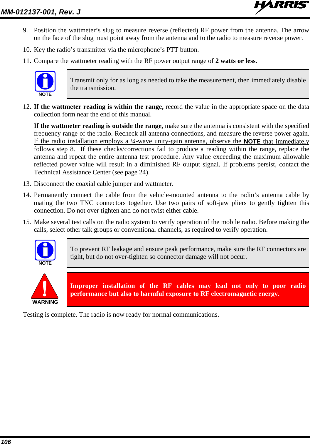
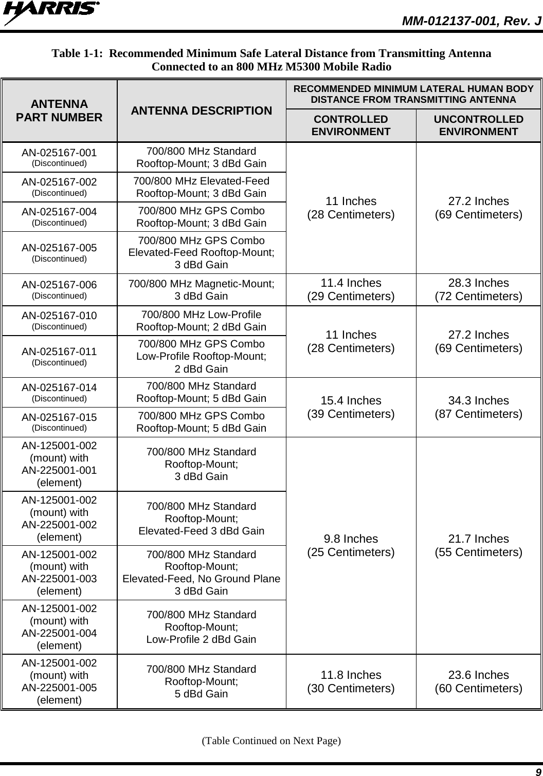
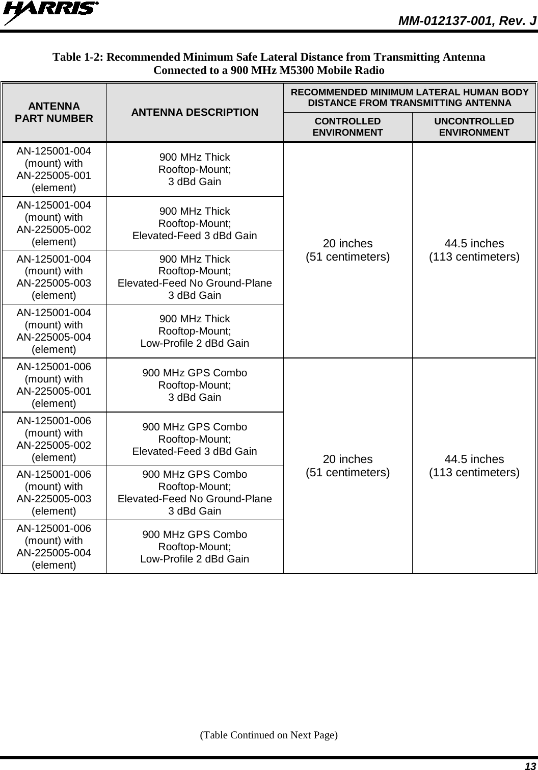
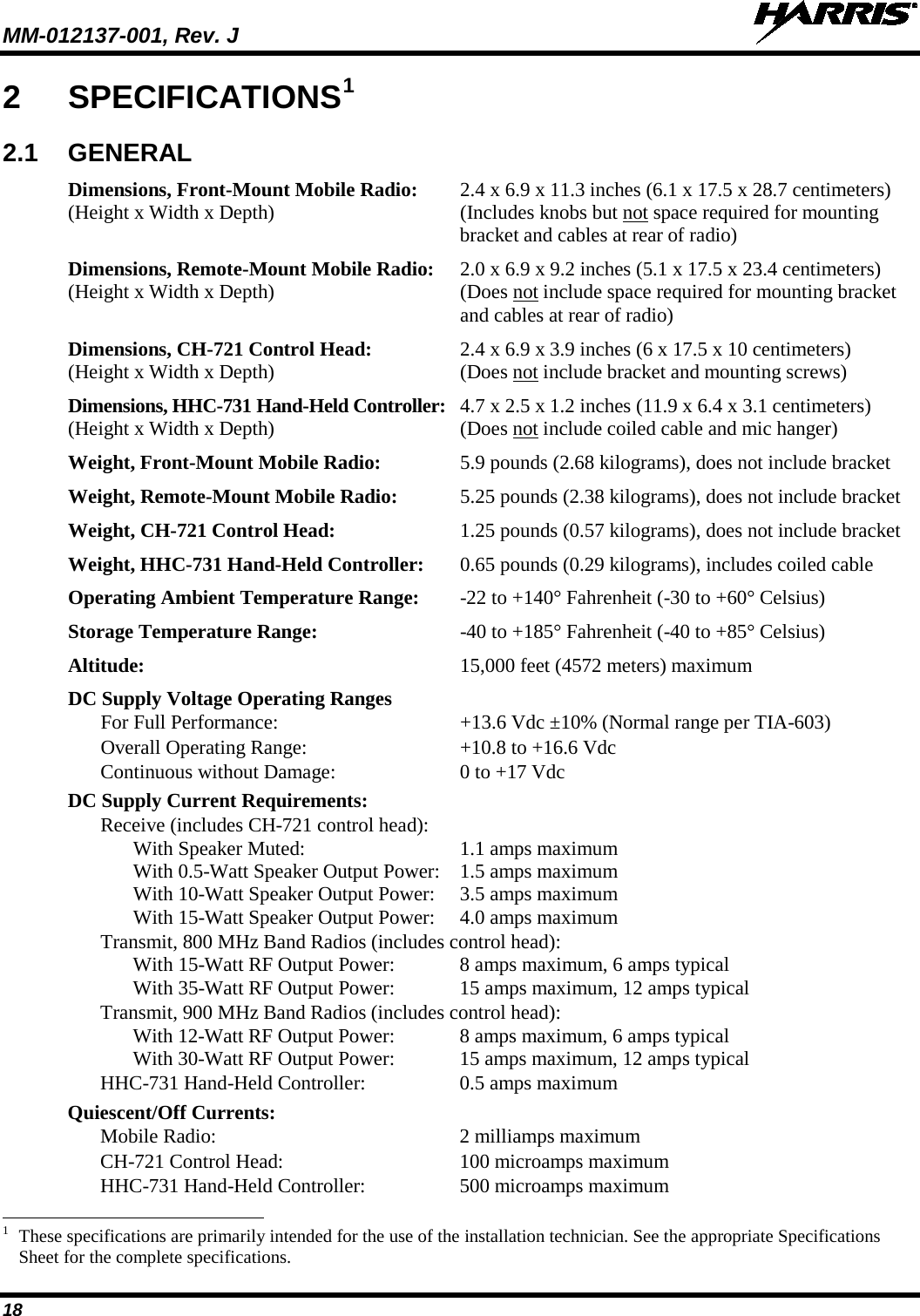
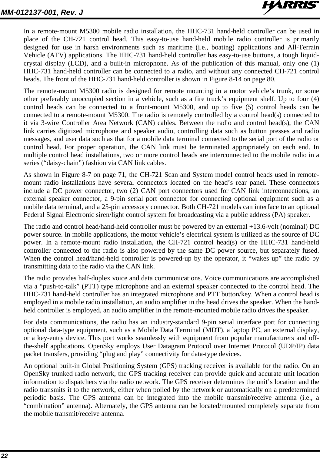
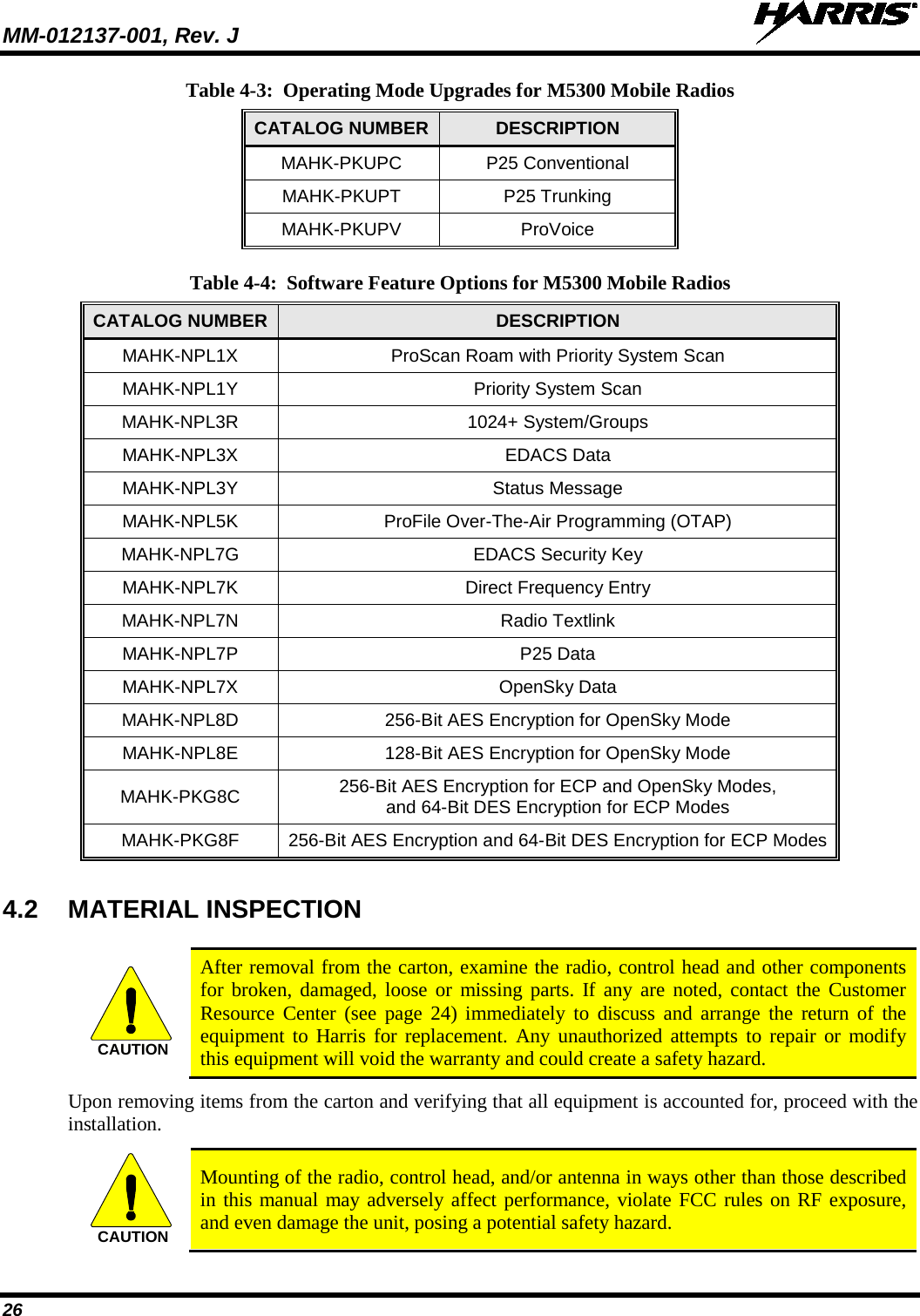
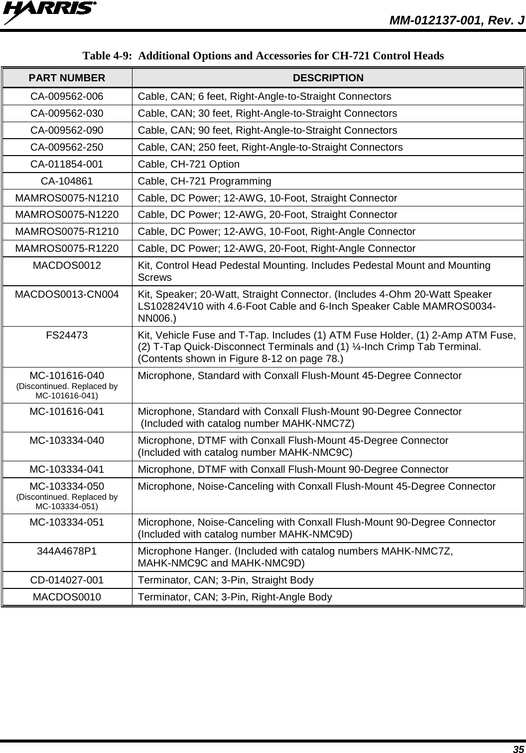
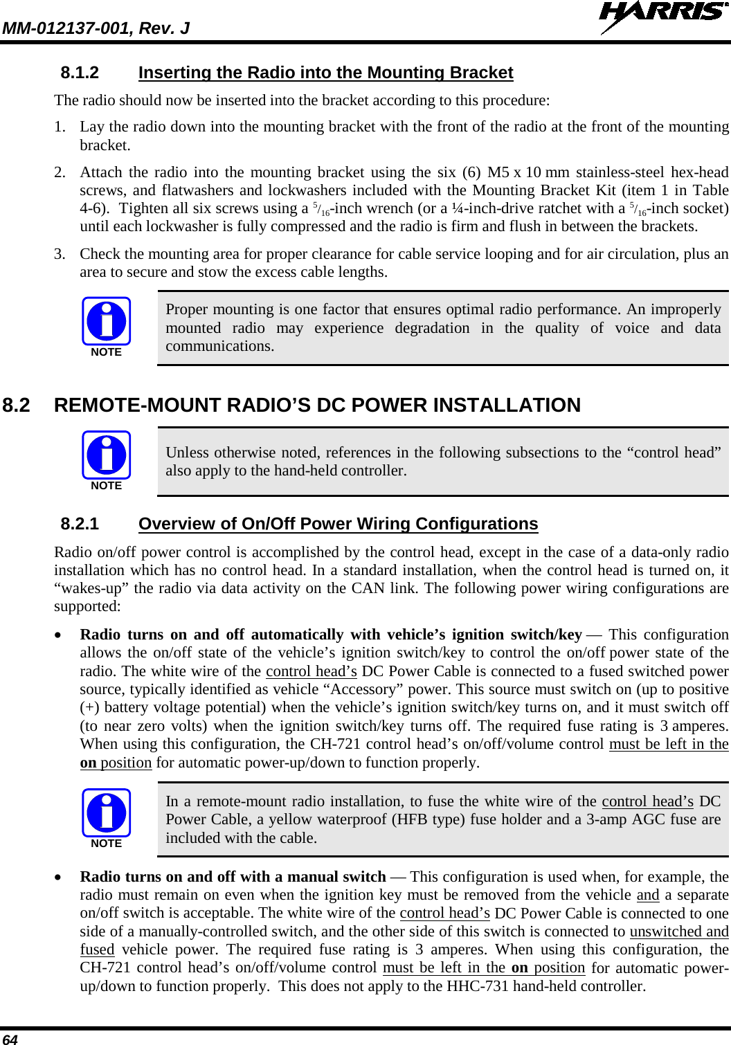
![MM-012137-001, Rev. J 63 3. If necessary, apply an approved paint or rust-inhibitor at the holes in the mounting surface. 4. Set the bracket back into place, and verify front-to-rear orientation. 5. Install and tighten the mounting screws/hardware. 6. Verify the bracket is firmly secured to the mounting surface. A secure mount prevents unreasonable vibration, which could damage the radio and/or cause its cable connections to loosen. TOP VIEW SIDE VIEW (Dimensions in Inches) FRONT VIEW (Dimensions in Inches) (Made From FM103111 Rev. B) Figure 8-3: Mounting Bracket FM103111V1 Dimensions [for Remote-Mount M5300 Mobile Radio (Radio Not Shown)] Bracket-To-Vehicle Screw Holes (4 places) Bracket-To-Radio Screw Holes (6 places, 3 each side) Rear of Bracket Front of Bracket](https://usermanual.wiki/HARRIS/TR-0049-E.Install-Manual/User-Guide-1331924-Page-63.png)
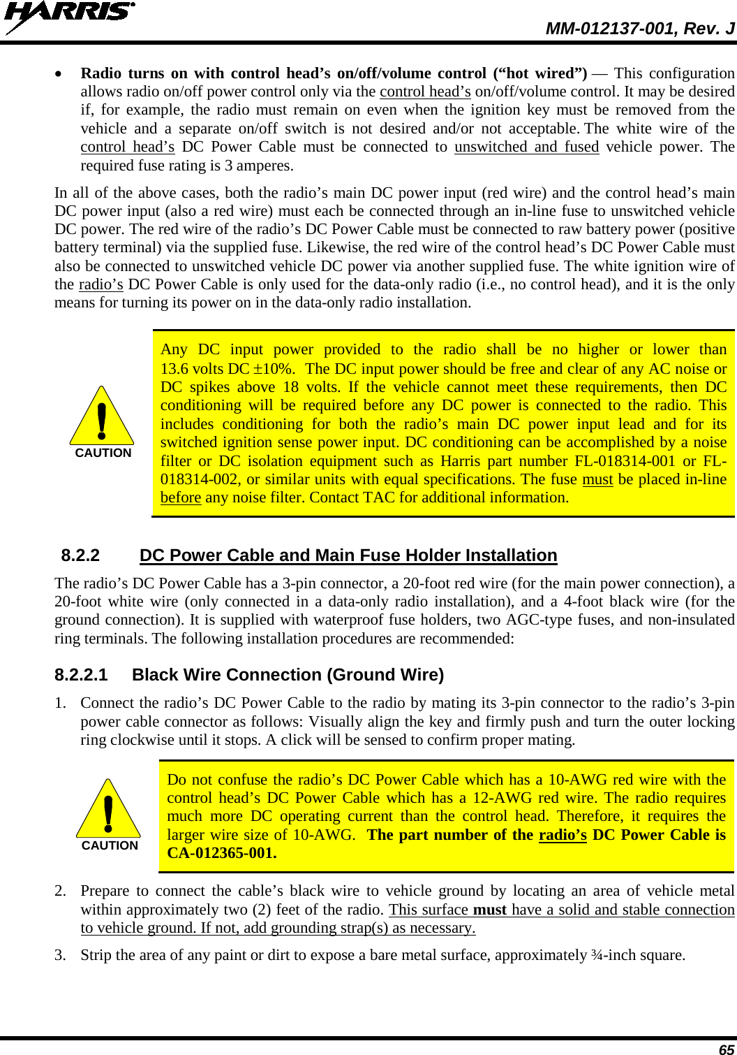
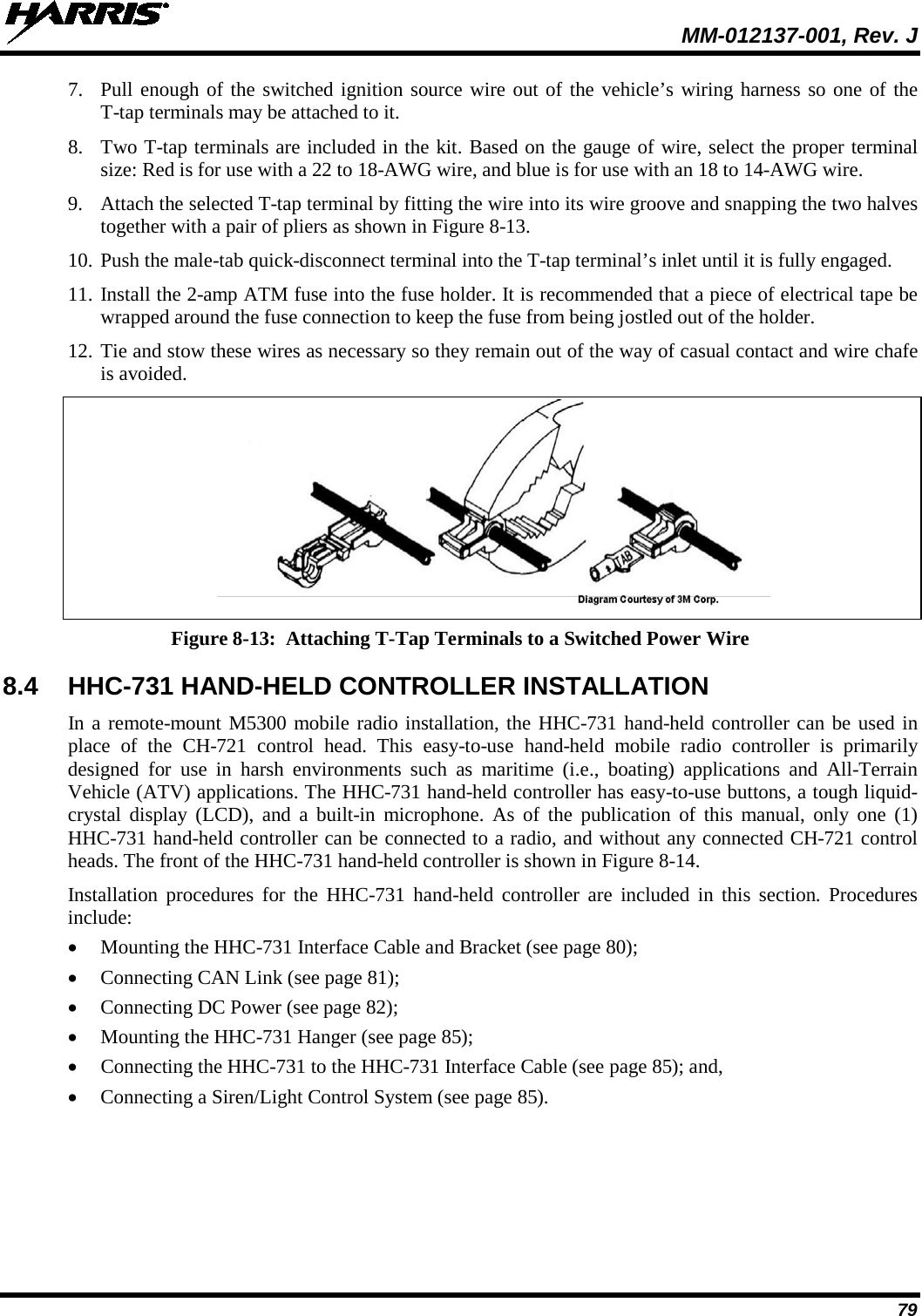
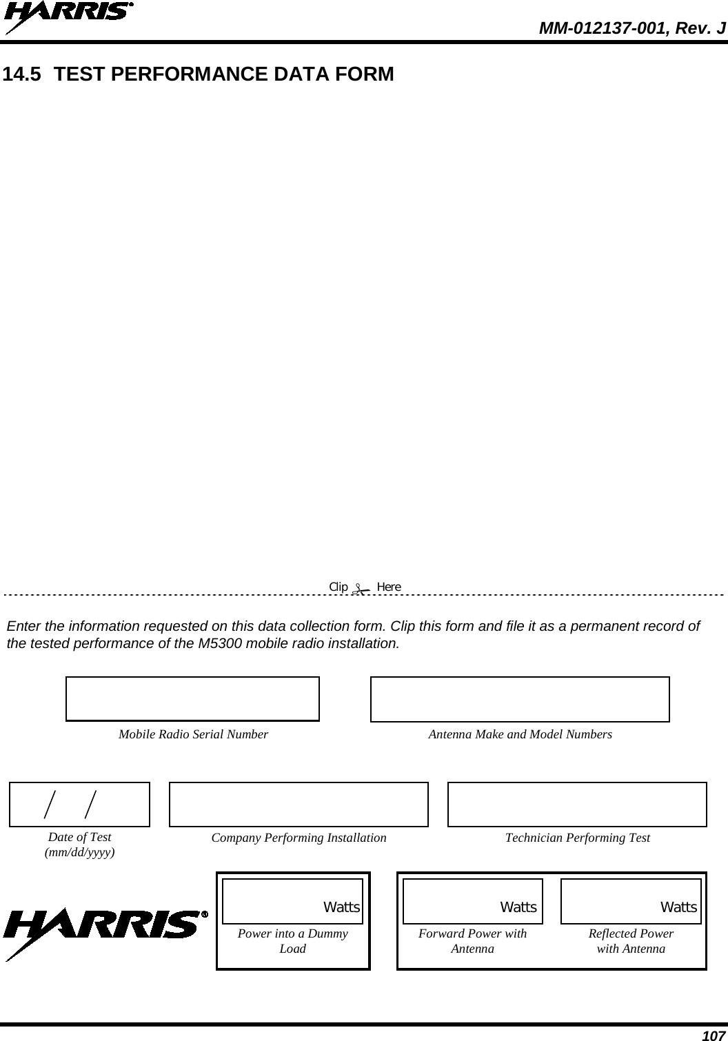
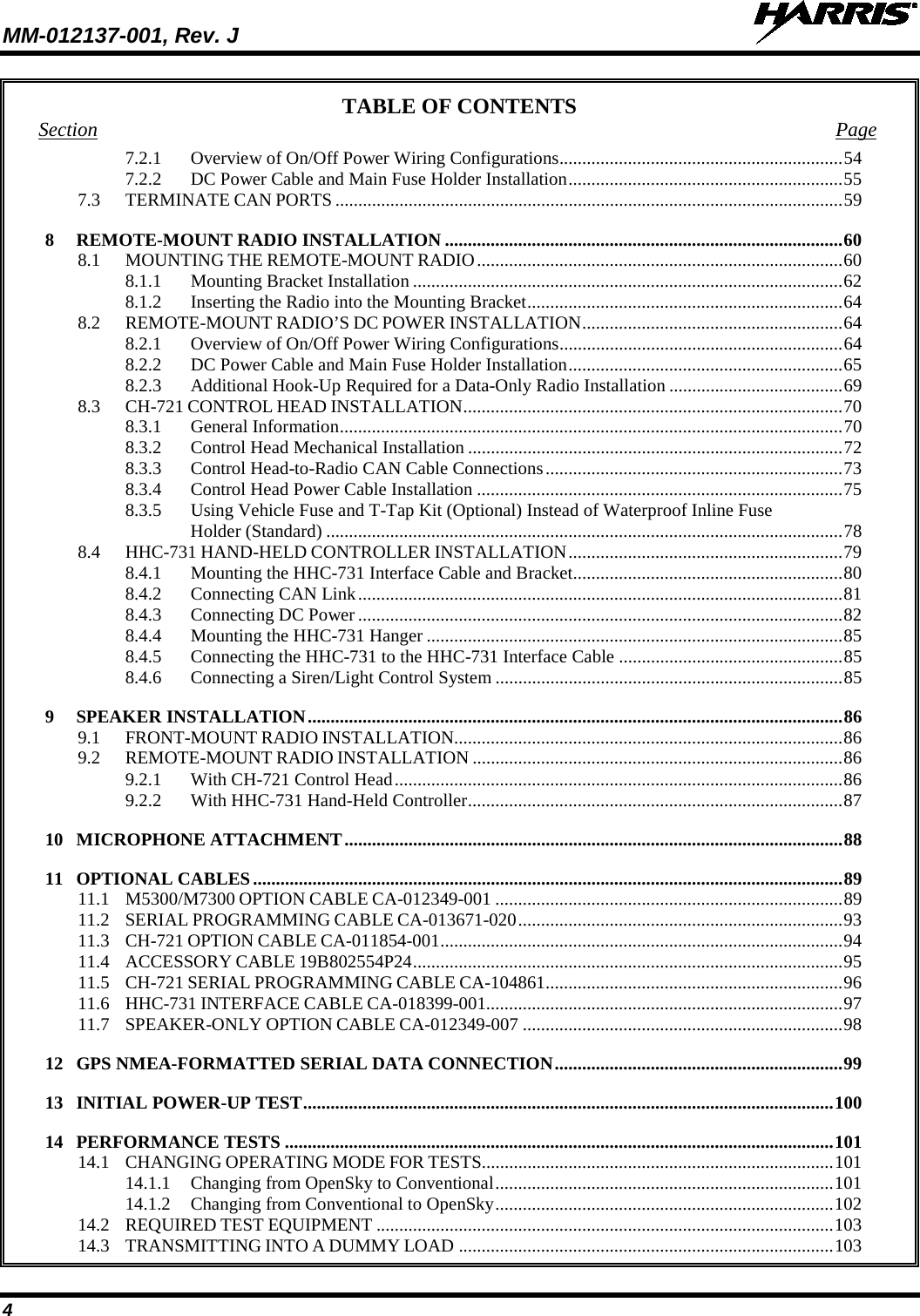
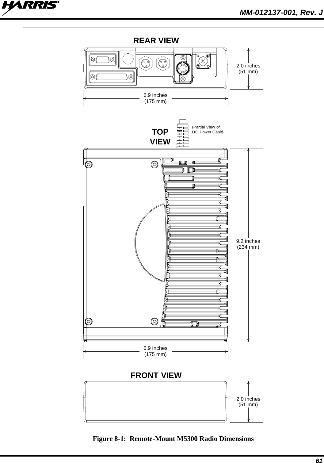
![MM-012137-001, Rev. J 66 Figure 8-4: Wiring Diagram for a Remote-Mount Radio Installation CH-721 SCAN MODELCONTROL HEADCU23218-0002(MAHK-NCP9E)CH-721 SYSTEM MODELCONTROL HEADCU23218-0004(MAHK-NCP9F)DTMFMICROPHONEMC-103334-040 ORMC-103334-041(INCLUDED WITHMAHK-NMC9C)STANDARD MICROPHONEMC-101616-040 ORMC-101616-041(INCLUDED WITHMAHK-NMC7Z)ORNOISE-CANCELINGMICROPHONEMC-103334-050 ORMC-103334-051(INCLUDED WITHMAHK-NMC9D)CH-721 MOUNTING BRACKET KITKT-008608[SUPPLIED WITH INSTALLATION KIT]• IF IGNITION SENSE ON/OFF FUNCTIONALITY IS REQUIRED, CONNECT WHITE WIRE OF CONTROL HEAD’S DC POWER CABLE TO A SWITCHED 13 VDC POWER SOURCE USING THE SUPPLIED FUSE AND FUSE HOLDER.• IF IGNITION SENSE ON/OFF FUNCTIONALITY IS NOT REQUIRED, CONNECT WHITE WIRE OF CONTROL HEAD’S DC POWER CABLE TO AN UNSWITCHED 13 VDC POWER SOURCE USING THE SUPPLIED FUSE AND FUSE HOLDER.WATERPROOF CAPFM-104859-001 (NOT SHOWN)FOR DB-9 SERIAL CONNECTOR[SUPPLIED WITH INSTALLATION KIT]WATERPROOF CAPFM-104859-002 (NOT SHOWN)FOR DB-25 ACCESSORY CONNECTOR[SUPPLIED WITH INSTALLATION KIT]REAR VIEW OF CONTROL HEADNEG POS3-AMP FUSE & FUSE HOLDER (HFB TYPE) REDRED RED5-AMPFUSE& FUSE HOLDER (HFB TYPE)3-AMP FUSE & FUSE HOLDER(HFB TYPE)15-AMPFUSE & FUSE HOLDER(HFB TYPE)REDWHITEREDRINGTERMINALSVEHICLEDC POWER DISTRI-BUTION BLOCK(E.G., “POWER ACCESS POINT”)VEHICLE BATTERY+-NOTE: BATTERY GROUND (-) CONNECTION NOT INDICATED.CAN TERMINATORCD-014027-001[SUPPLIED WITH INSTALLATION KIT]REDWHITEBLACK(SHORT AS POSSIBLE)RING TERMINAL (CONNECT TO VEHICLE CHASSIS GROUND)CAN CABLE CA-009562-030 (30 FEET LONG) [SUPPLIED WITH INSTALLATION KIT]SPEAKER CABLEMAMROS0034-NN006[SUPPLIED WITHINSTALLATION KIT]EXTERNAL SPEAKERLS102824V10[SUPPLIED WITHINSTALLATION KIT] WHITE WIRE OF RADIO’S DC POWER CABLE (LABELED AND COILED NEAR VEHICLE’S FUSE BOX)DC POWER CABLE CA-012616-001(SUPPLIED WITH INSTALLATION KIT)VEHICLE FUSE BOX, ETC.WHITE](https://usermanual.wiki/HARRIS/TR-0049-E.Install-Manual/User-Guide-1331924-Page-66.png)
![MM-012137-001, Rev. J 67 Figure 8-4: Wiring Diagram for a Remote-Mount Radio Installation (Cont.) GPS ANTENNA(OPTIONAL; SEE TEXT FOR SPECIFIC PART NUMBERS)DC POWER CABLECA-012365-001(SUPPLIED WITH INSTALLATION KIT)RING TERMINAL (CONNECT TO VEHICLE CHASSIS GROUND)BLACKBLACKREDWHITEM5300 MOBILE RADIO800 MHz = RU-144750-061900 MHz = RU-144750-181REAR VIEWMOBILEANTENNA(OPTIONAL;SEE TEXT FOR SPECIFIC PART AND OPTION NUMBERS)MALE TNC RF CONNECTOR(SUPPLIED WITH ANTENNA)CAN TERMINATORCD-014027-001[SUPPLIED WITH INSTALLATION KIT]](https://usermanual.wiki/HARRIS/TR-0049-E.Install-Manual/User-Guide-1331924-Page-67.png)