HARRIS TR-0049-E M5300 900 MHz Mobile Radio User Manual MM 012125 001 Rev D M5300 Series Mobile Radio
HARRIS CORPORATION M5300 900 MHz Mobile Radio MM 012125 001 Rev D M5300 Series Mobile Radio
HARRIS >
Contents
- 1. Manual
- 2. Manual 1
- 3. Manual 2
- 4. Operators Manual
- 5. Install Manual
Operators Manual
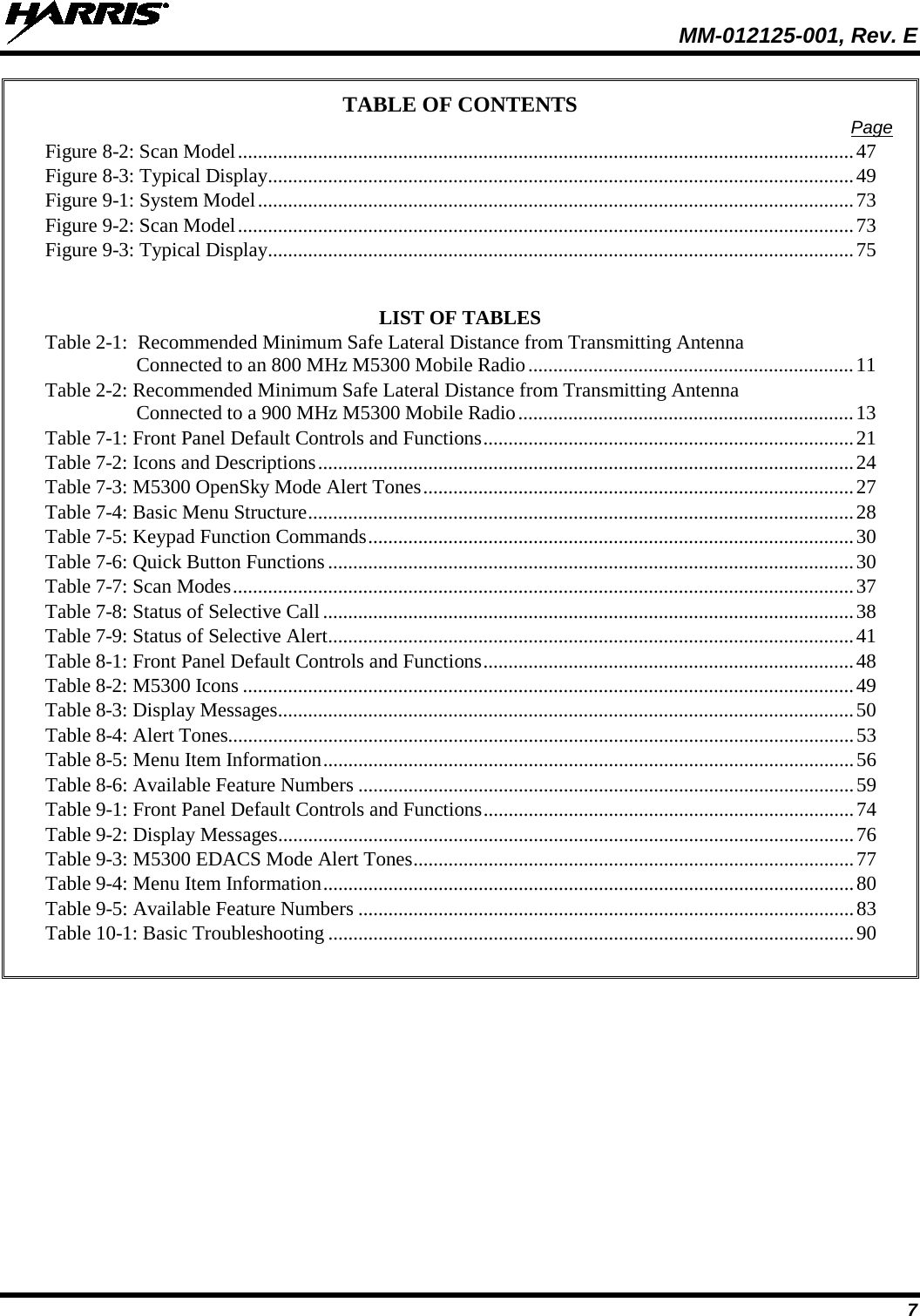

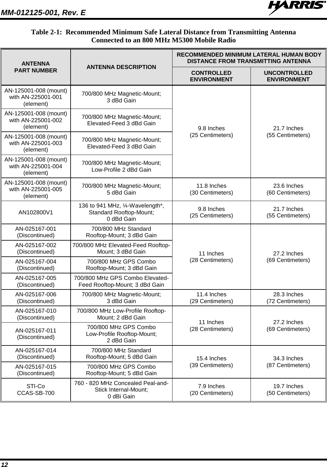
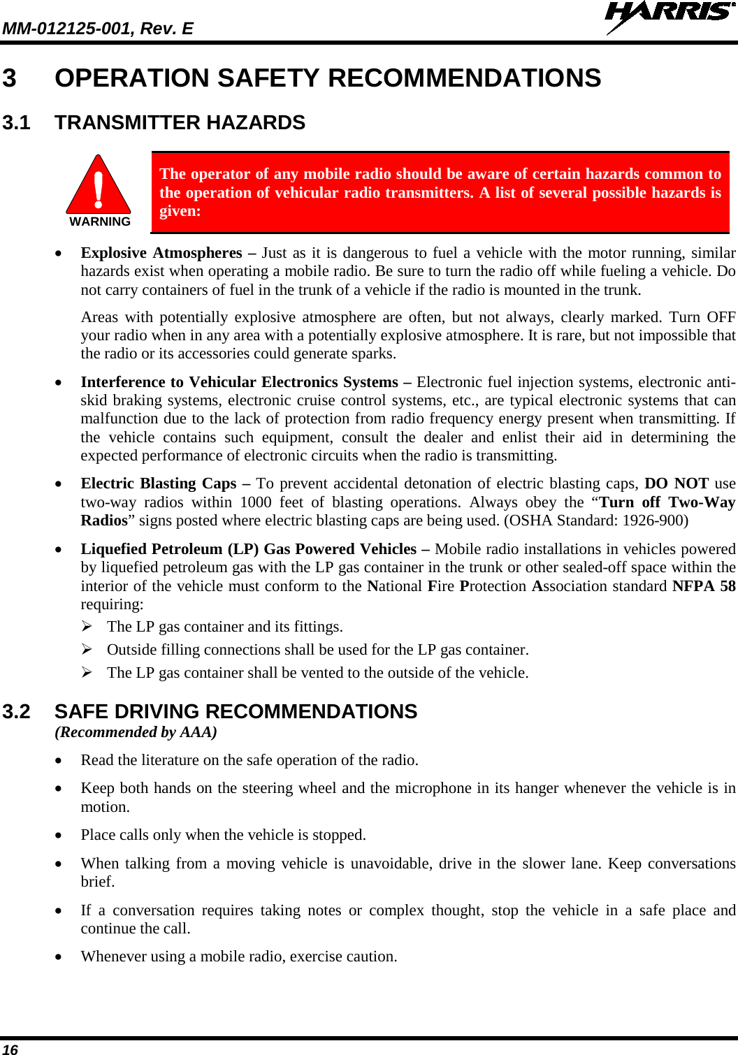
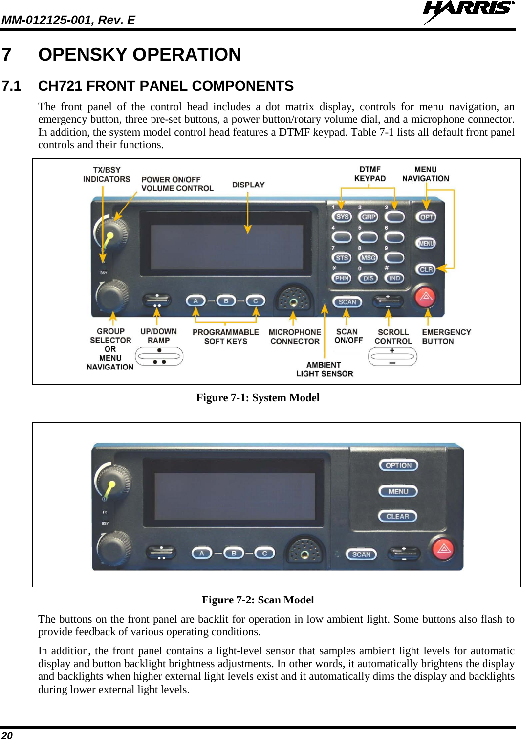
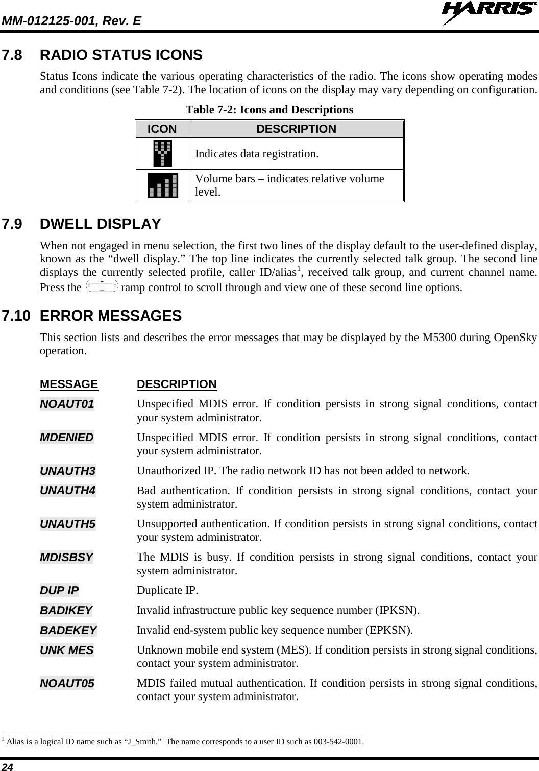
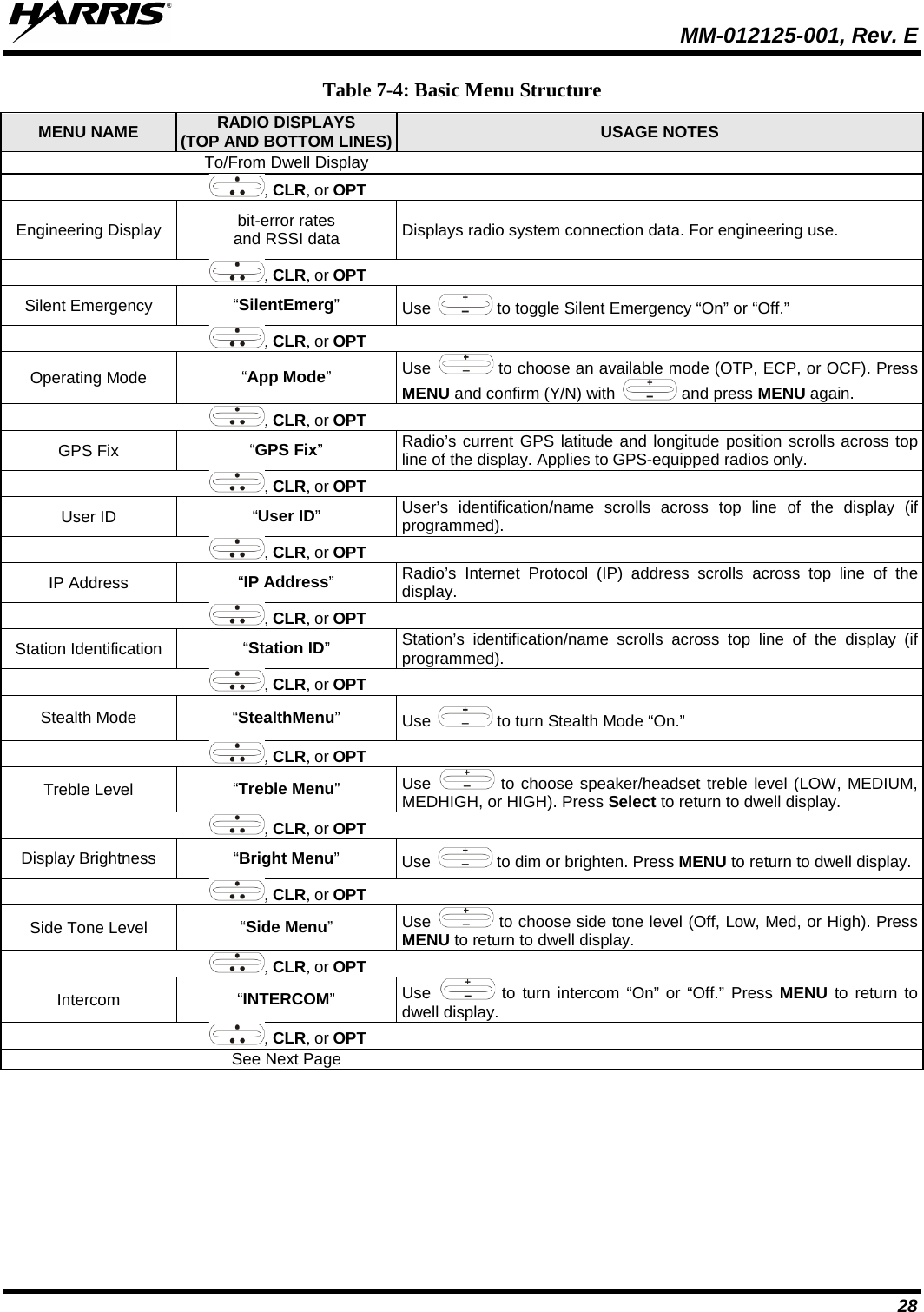
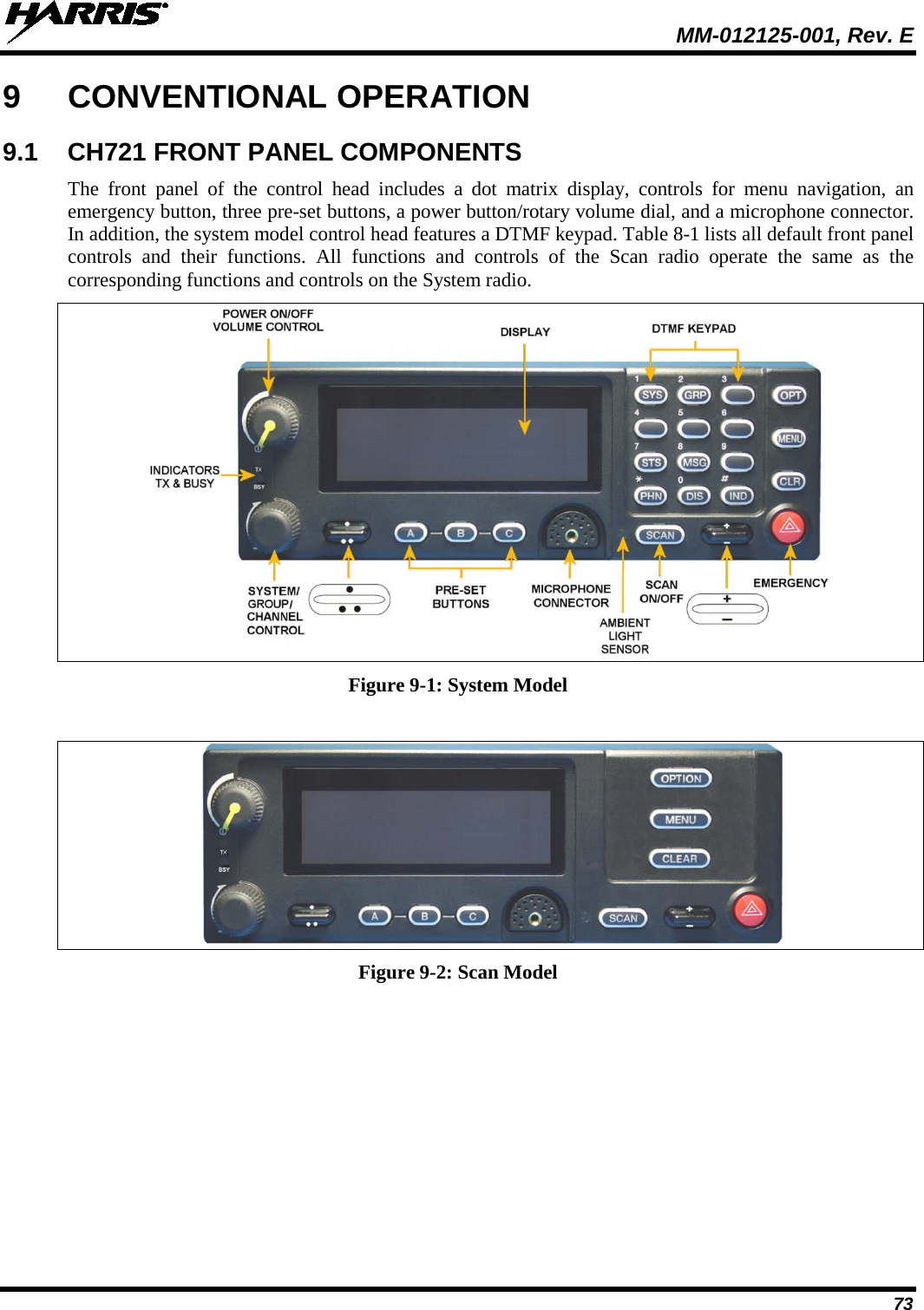
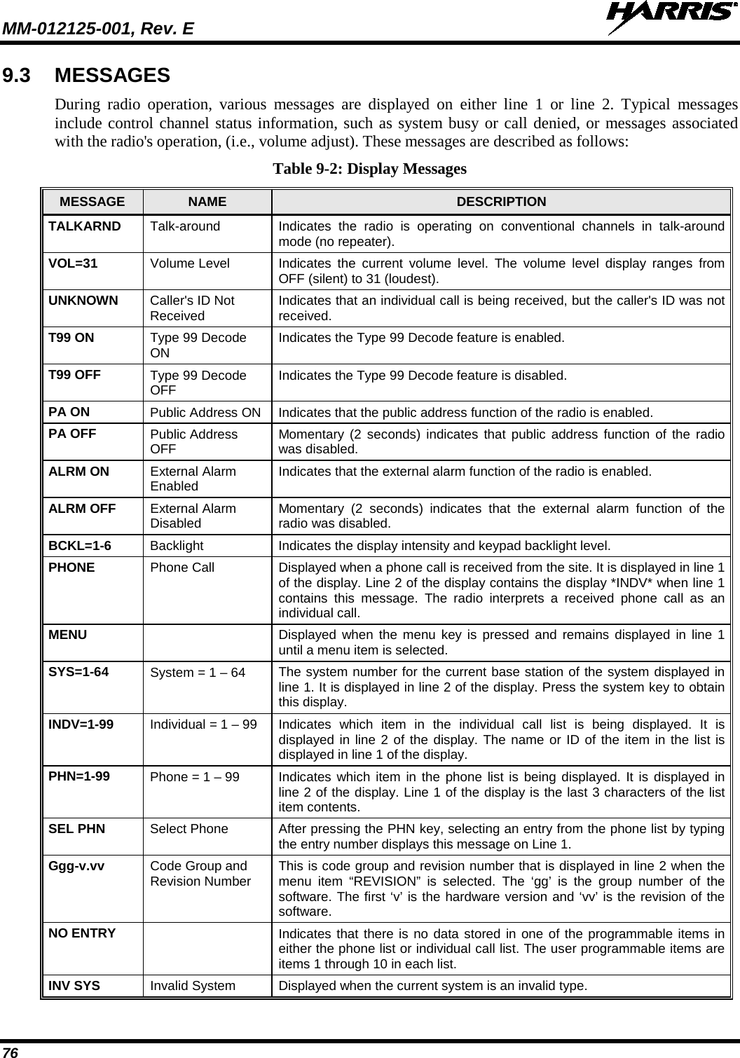
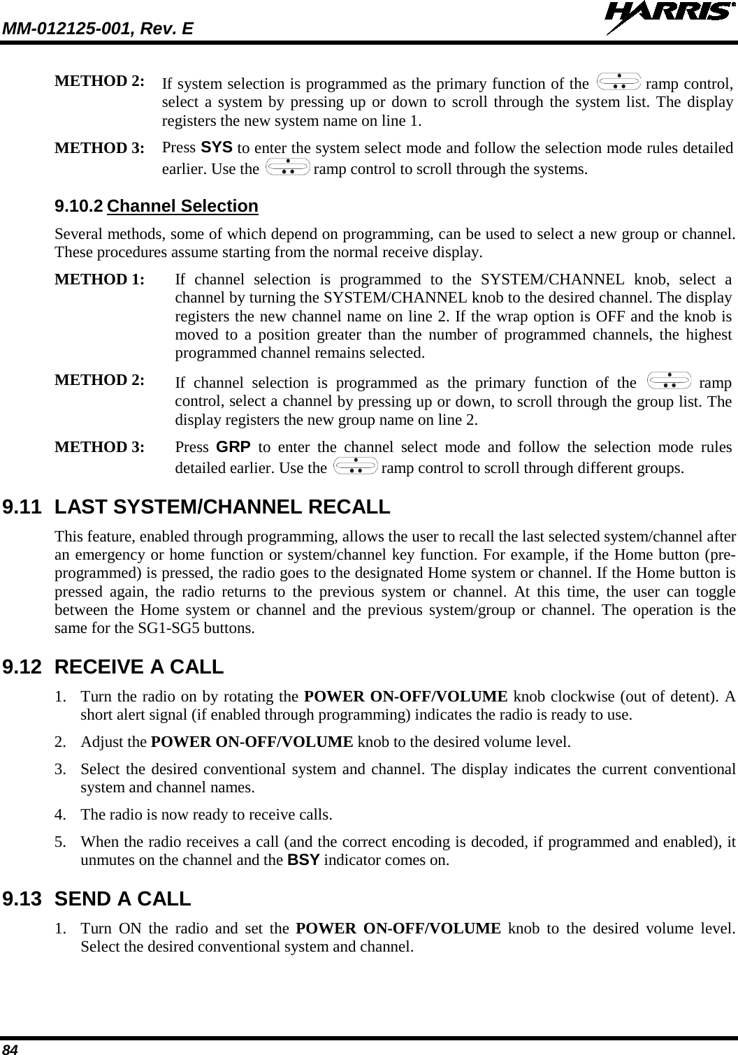
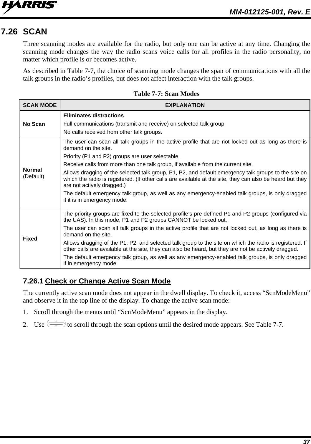
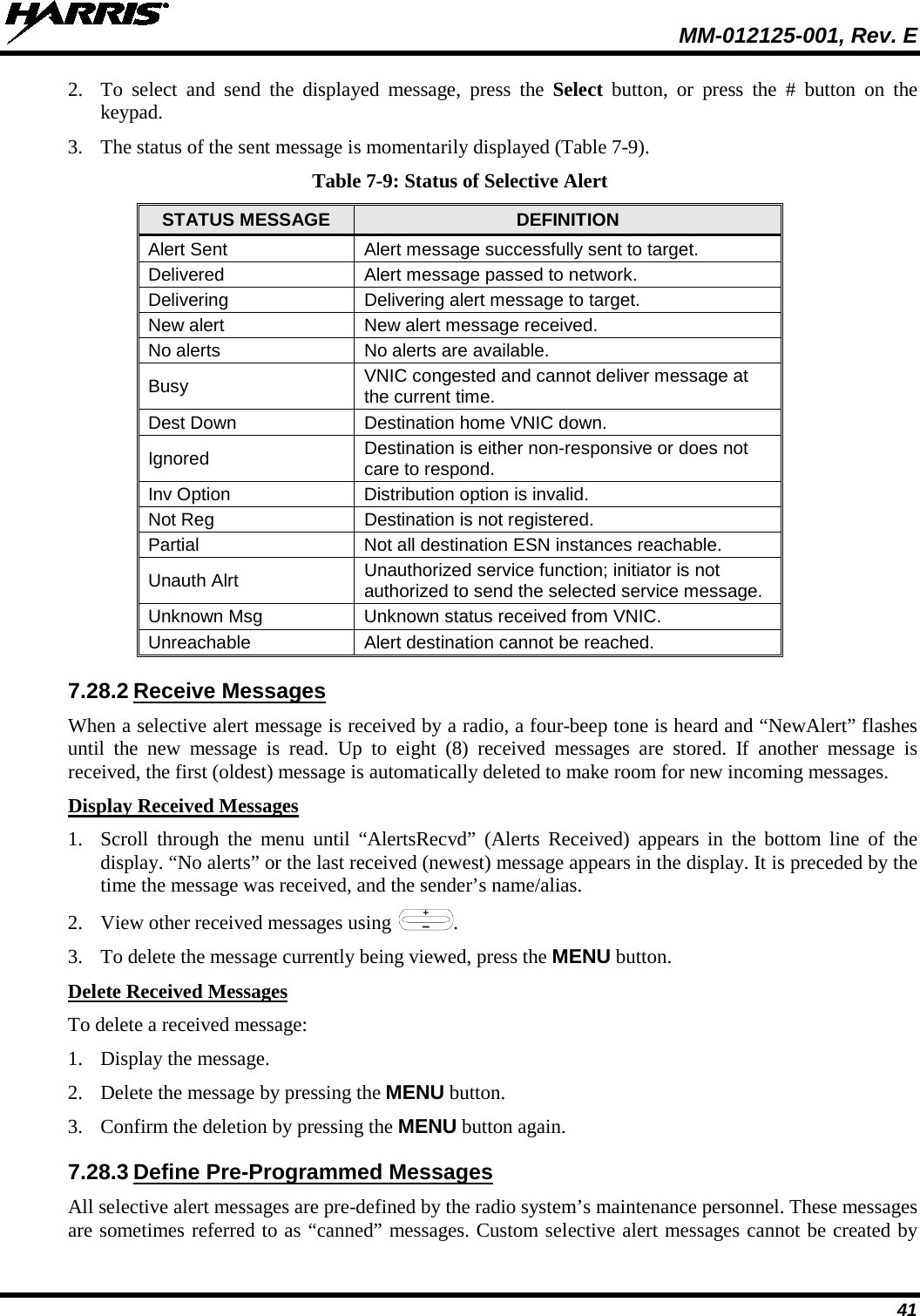
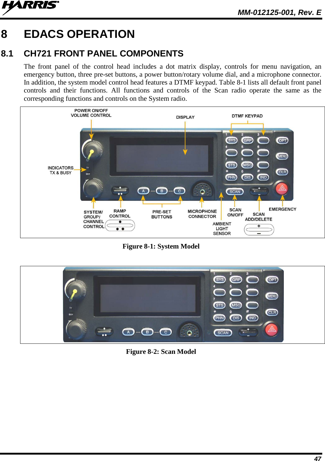
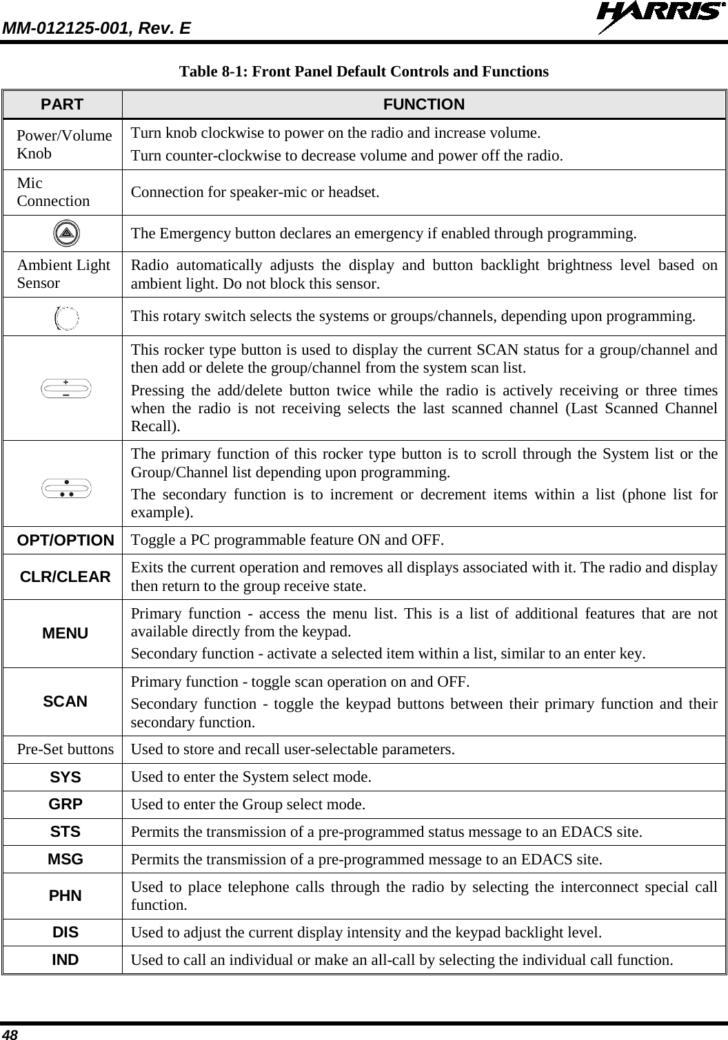
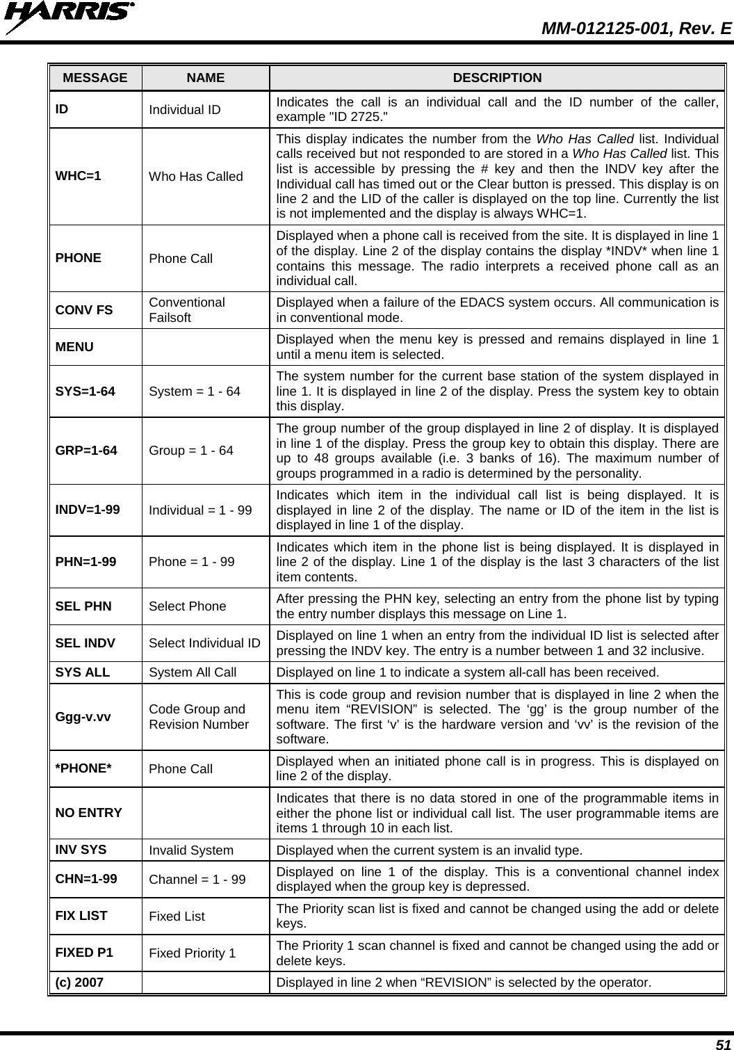
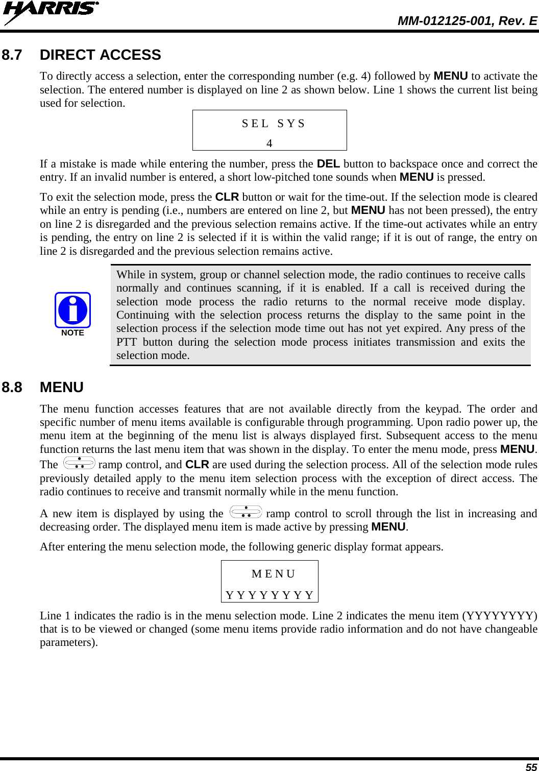
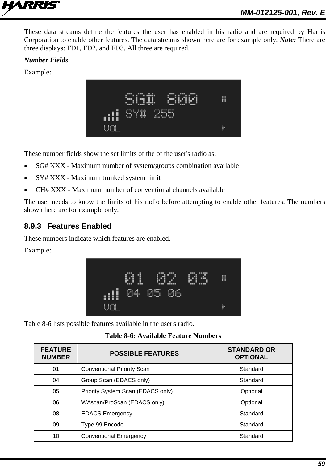
![MM-012125-001, Rev. E 30 7.14 DUAL-TONE MULTI-FREQUENCY Dual-Tone Multi-Frequency (DTMF) is the system used by touch-tone telephones. DTMF assigns a specific tone frequency to each key so a microprocessor can easily identify its activation. The radio supports DTMF with a system model control head (Figure 7-1). This allows for specific tasks such as entering a user ID and password, or selective calling. When a key on the DTMF keypad is pressed, a single low-pitched tone is heard from the microphone. The key tones are not adjustable. 7.15 KEYPAD 7.15.1 Keypad Commands (System Model Control Head) To perform a command from the keypad, press the * key followed by one of the pre-set function keys as follows: Table 7-5: Keypad Function Commands KEYPAD COMMAND FUNCTION *0 Log off command: *0## (logs the user off the system). See page 23 for additional information. *1 Login command: *1<User ID> # <Password> ##. *4 Enter Scene of Incident Mode (SOI) on specified channel and band: *4#<ccc>#<bb># where ccc is the SOI channel number and bb is the number assigned to each frequency band. Press *40# to exit SOI mode. *6 Go to default profile. *7 Initiate Selective Alert command: *7<Target ID>#[Choose Message]#. See page 40 for additional information. *8 Radio-to-Radio Call command: *8<Selective call number># (PTT to dial). *9 Public Switched Telephone Network (PSTN) Call command: *9 <telephone number># (PTT to dial). See page 42 for additional information. 7.15.2 Quick Buttons (System Model Only) Quick Keys are a two-button sequence that gives the radio user quick access to certain menu items. Quick keys act as a toggle function. Table 7-6: Quick Button Functions QUICK KEYS FUNCTION 1# Transition to ECP mode. If ECP is not loaded in the radio, the radio displays “No App.” 2# Stealth Mode On/Off. 3# Scan Mode On/Off. • If the Scan Mode is Normal when the Scan Mode is toggled Off, the Scan Mode is Normal when toggled On again. • If the Scan Mode is Fixed when the Scan Mode is toggled Off, the Scan Mode is Fixed when scan mode is toggled On again. • If the Scan Mode is Off when the radio boots up, the Scan Mode is Normal when Scan Mode is toggled On.](https://usermanual.wiki/HARRIS/TR-0049-E.Operators-Manual/User-Guide-1331923-Page-30.png)
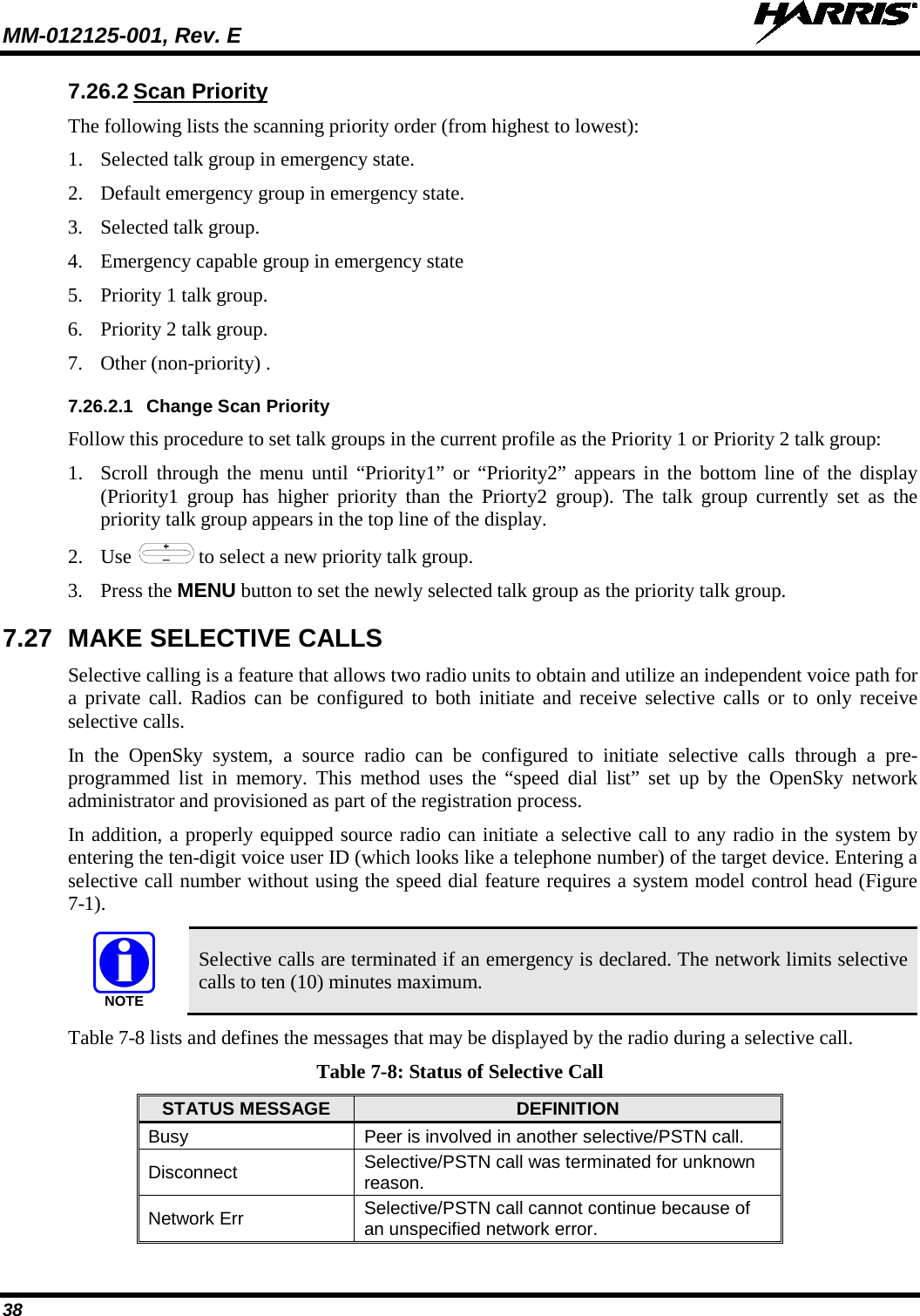
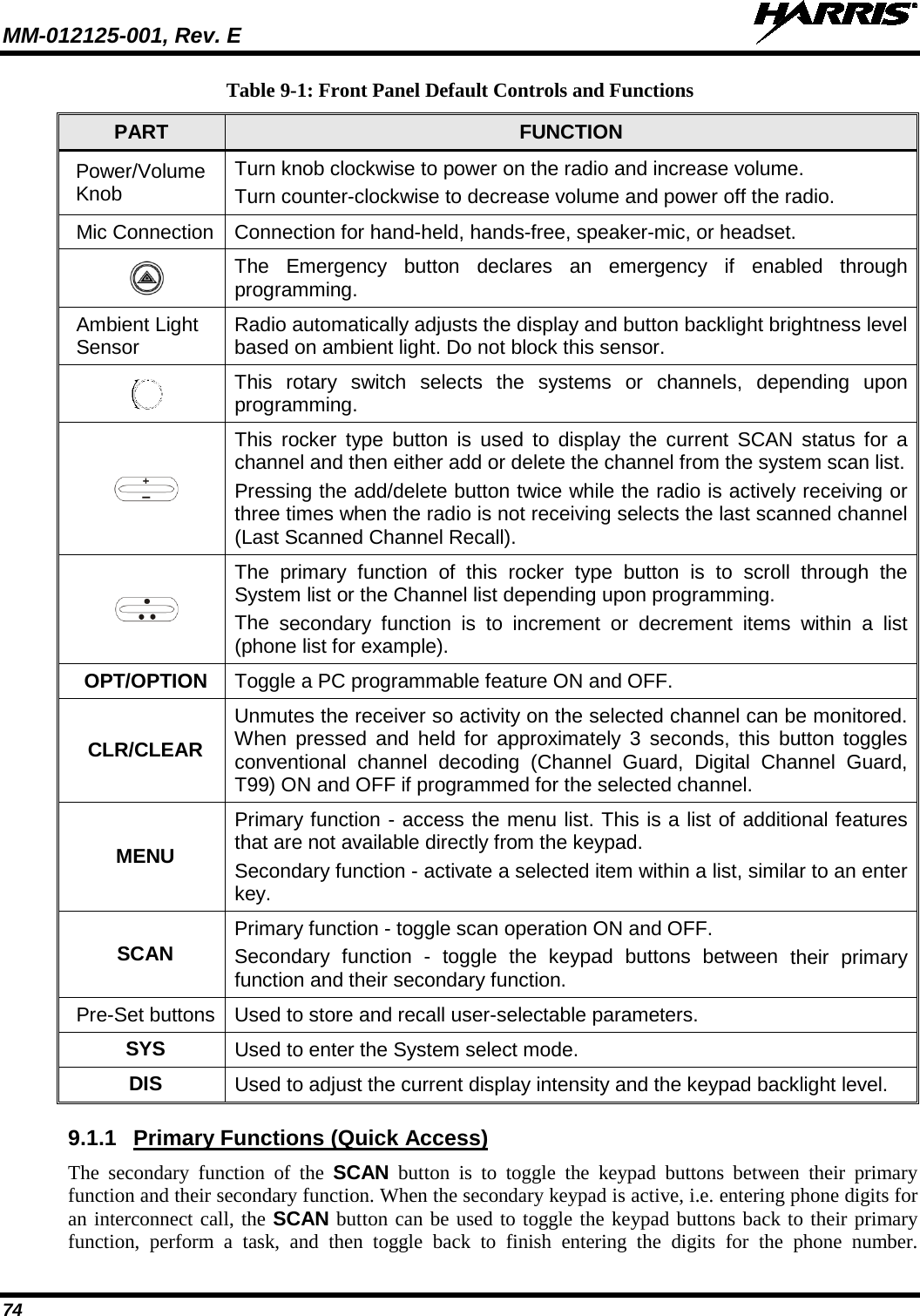
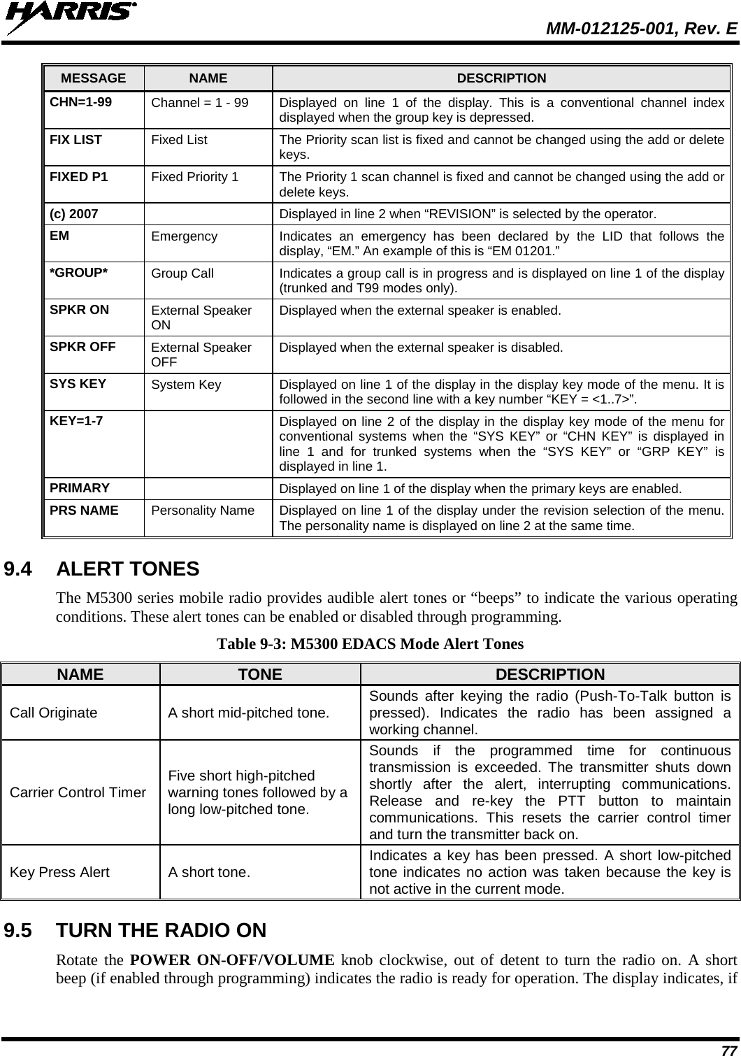
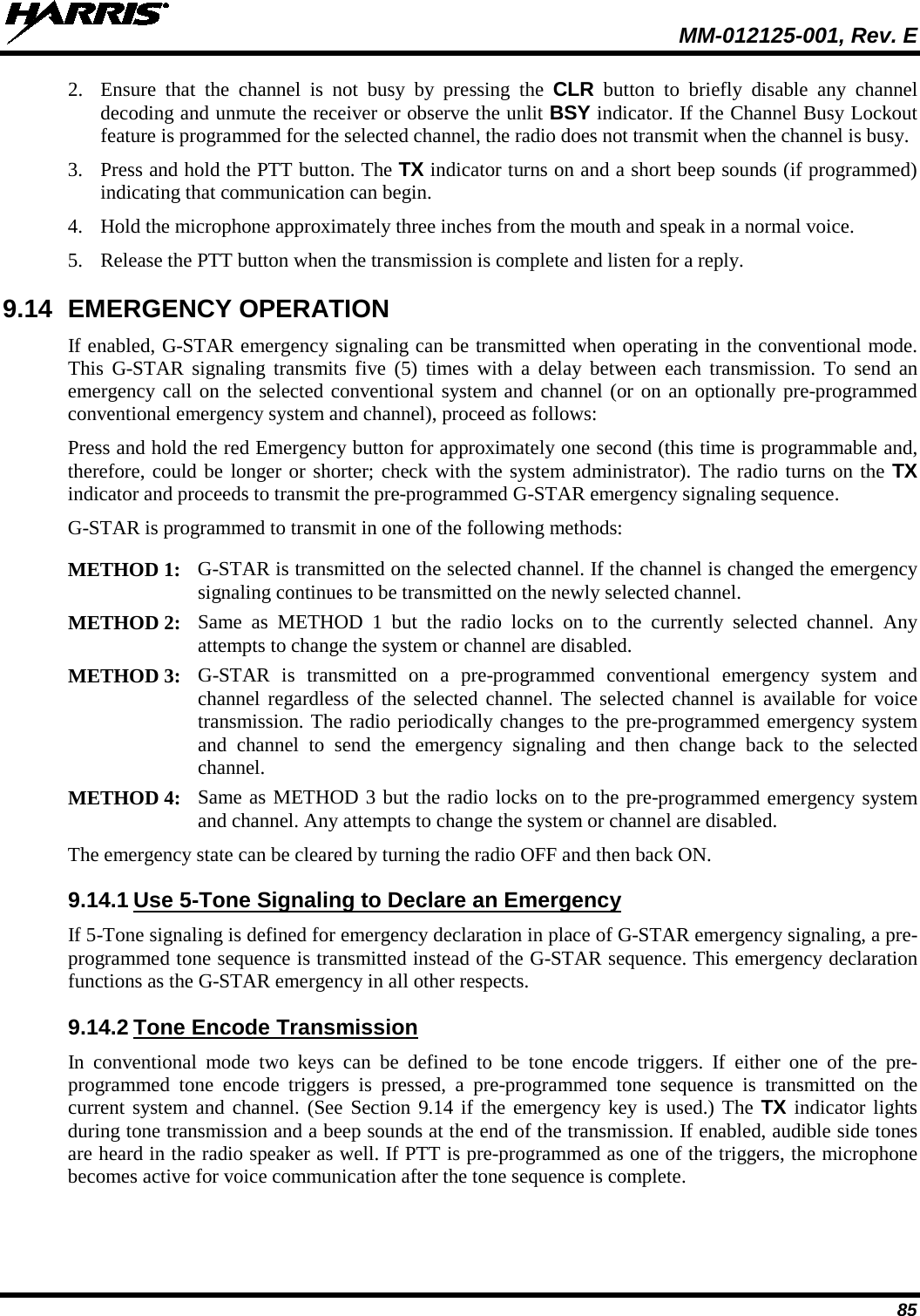
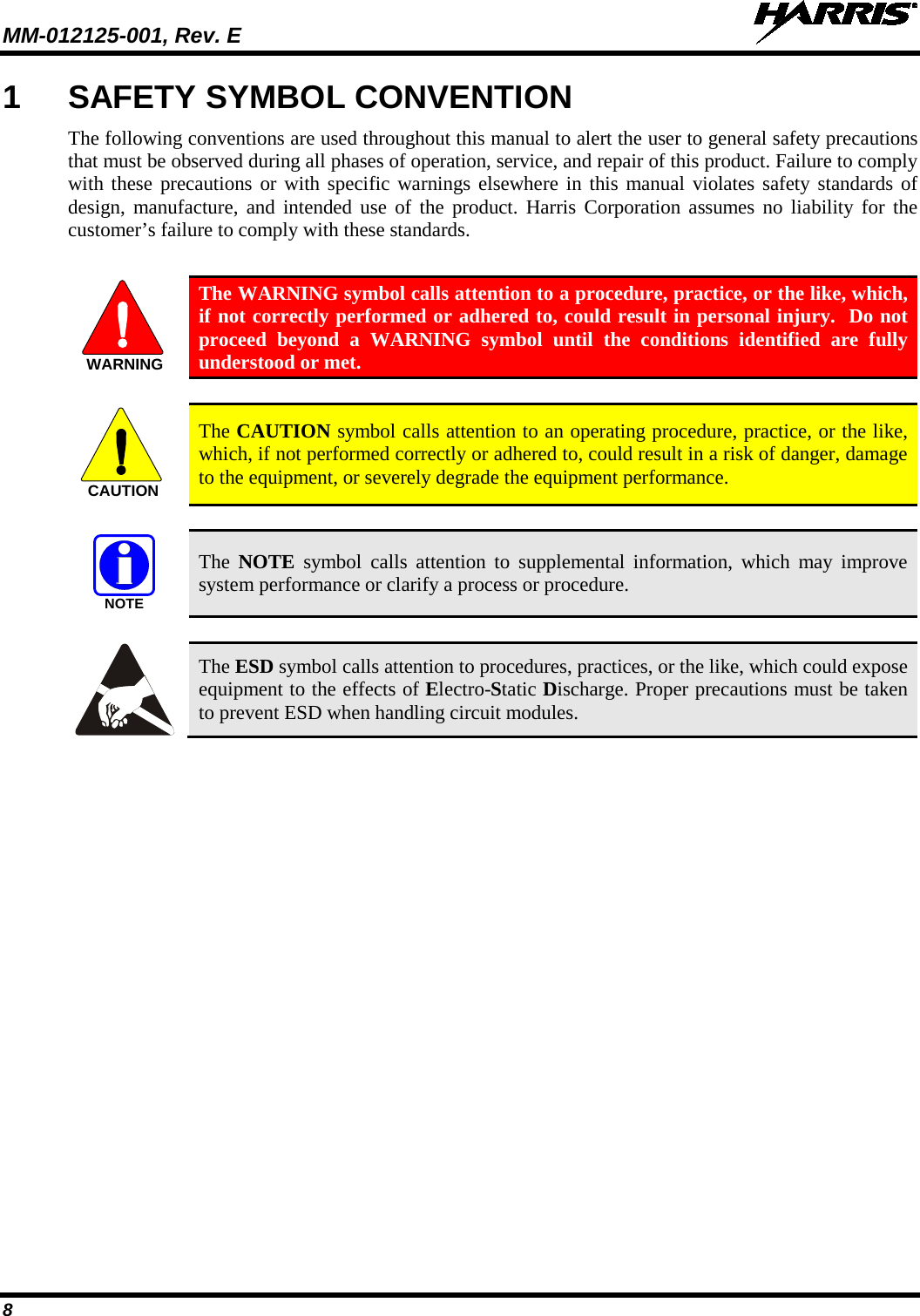
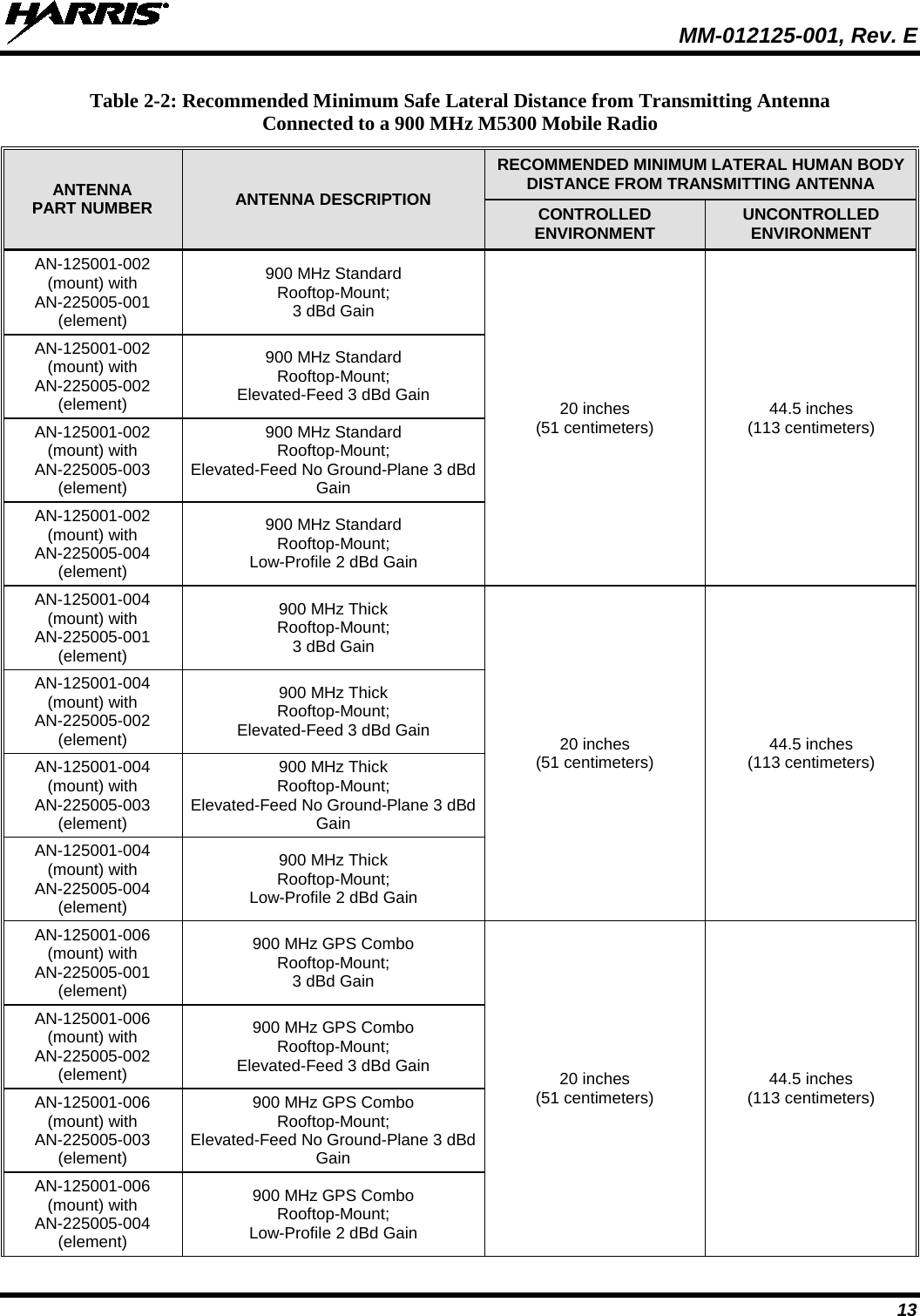
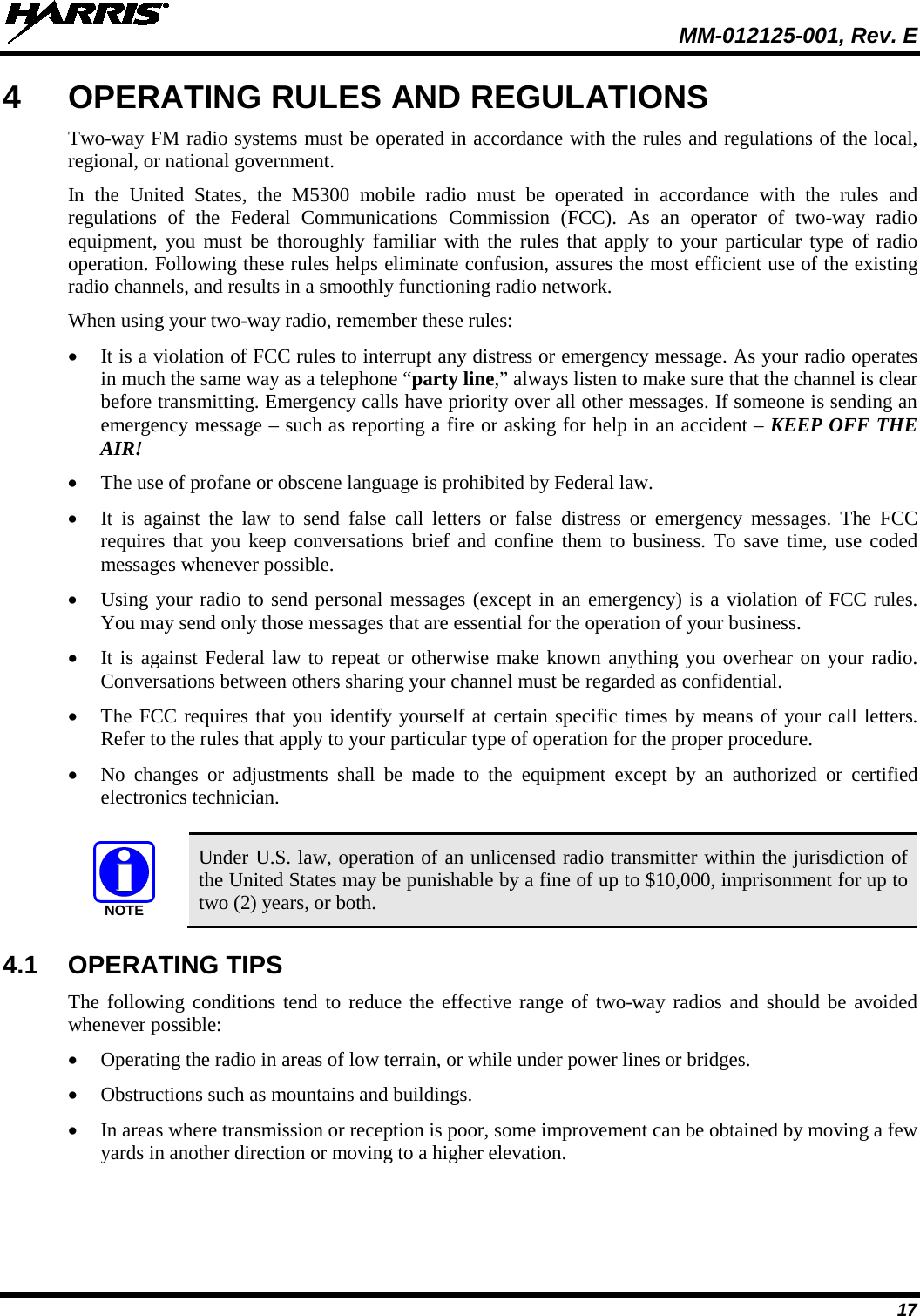
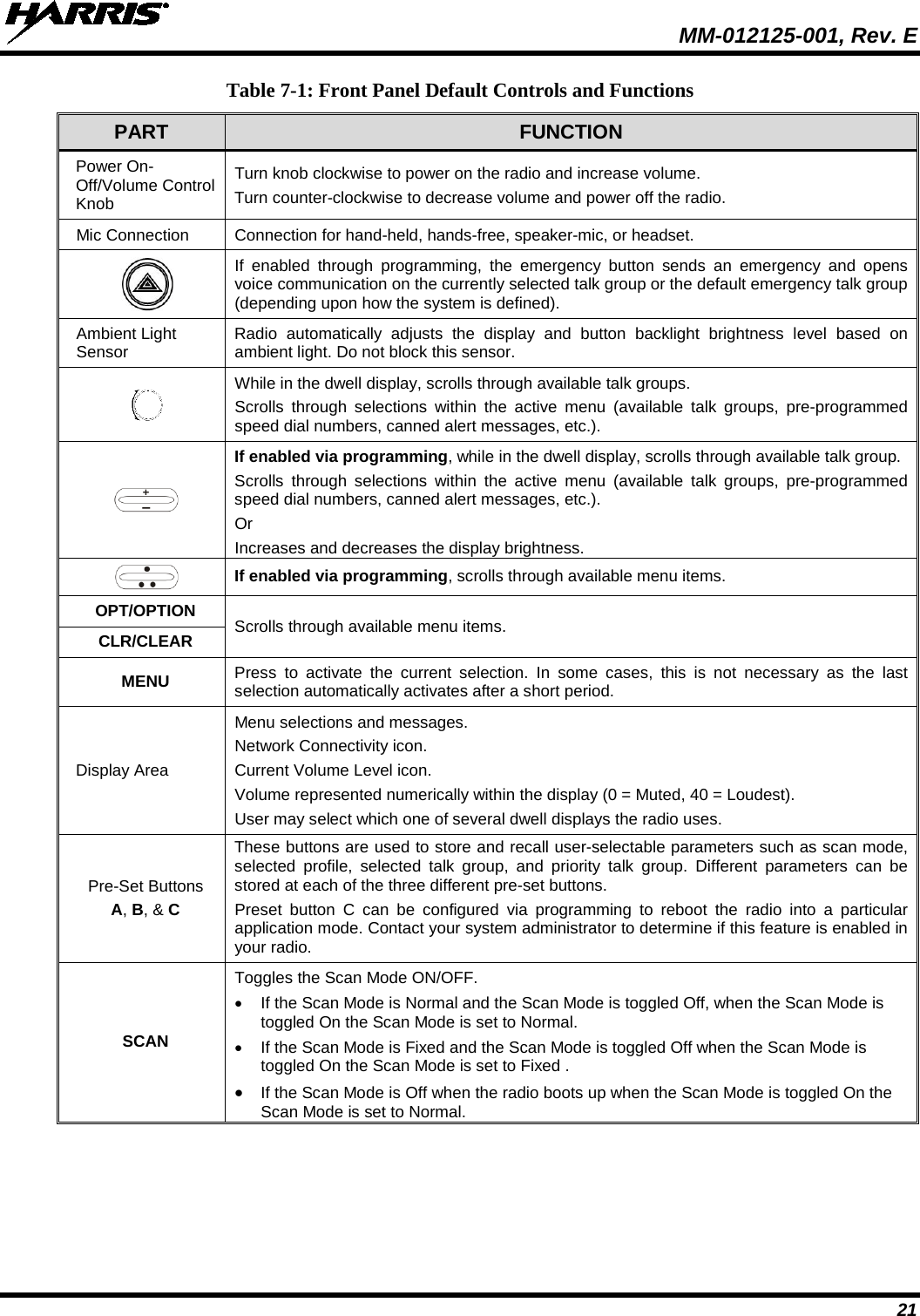
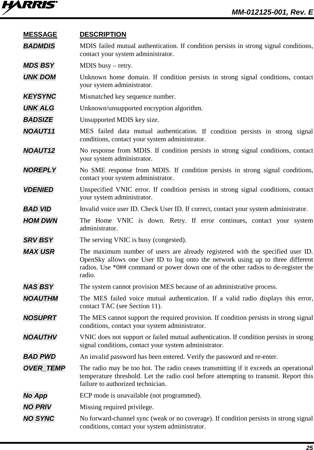
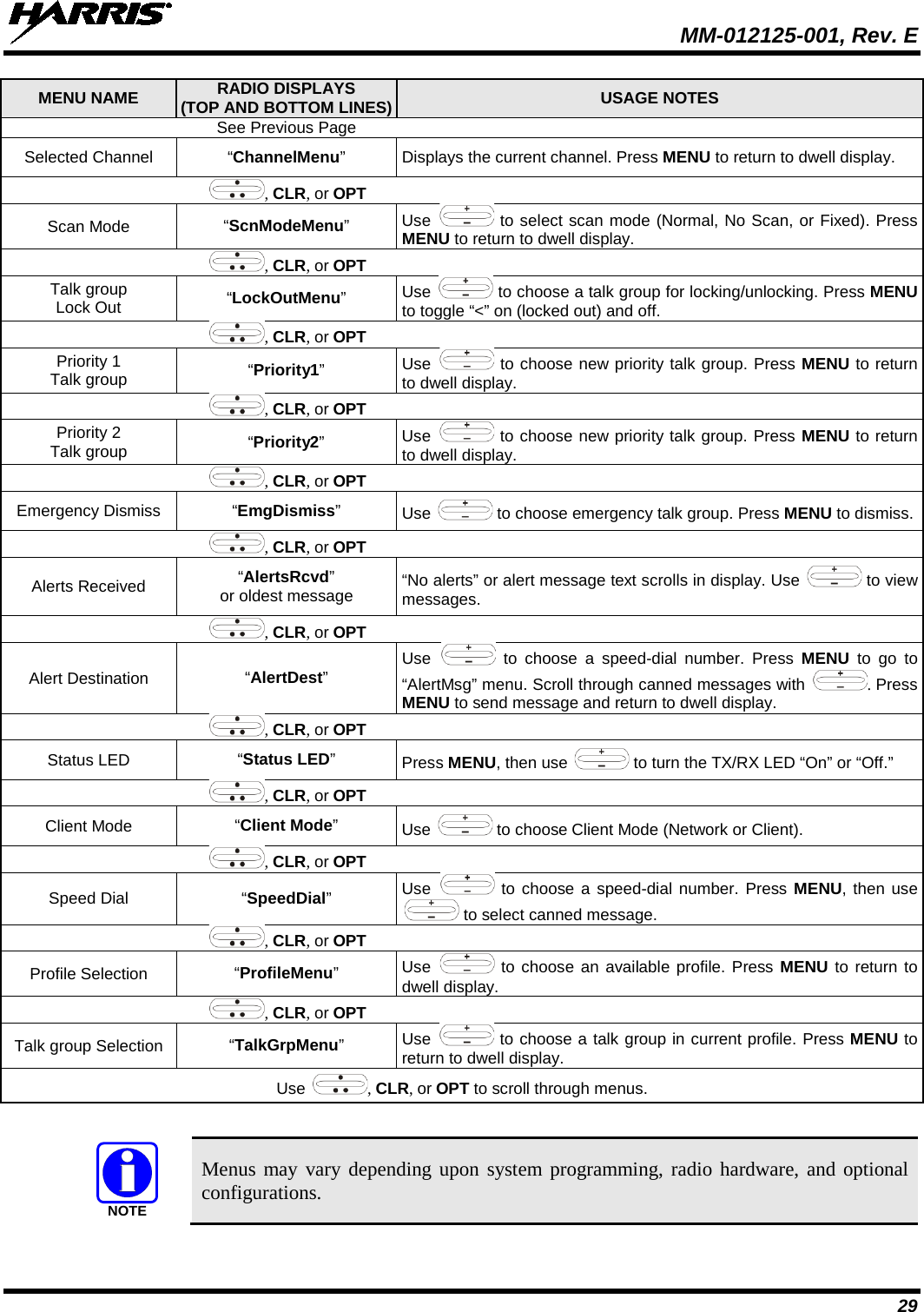
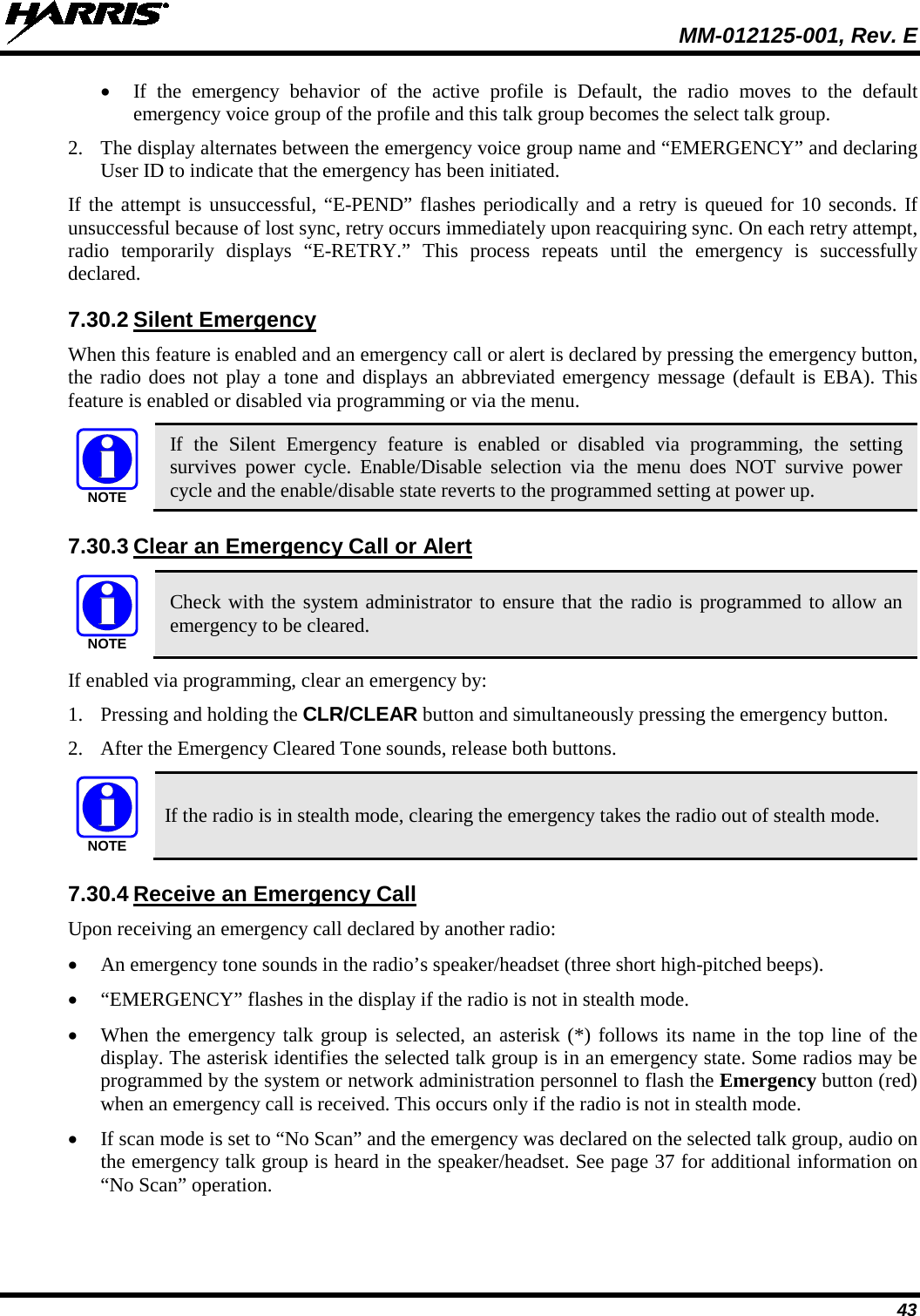
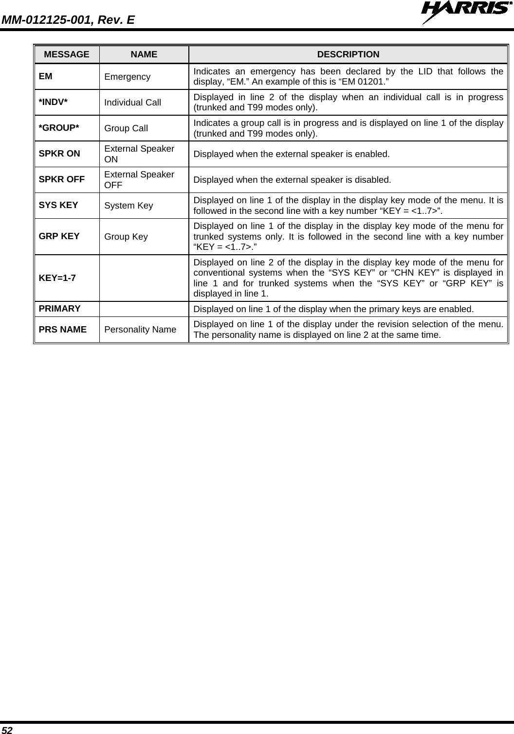
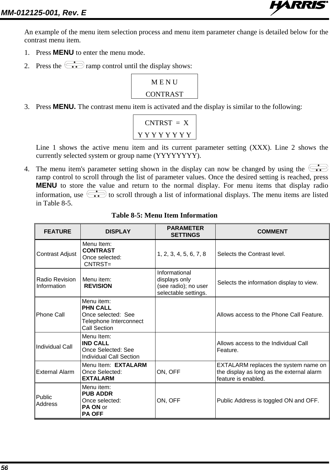
![MM-012125-001, Rev. E 42 the radio user. The entire selective alert message, including the abbreviation, can include up to two hundred (200) text characters. 7.29 TELEPHONE INTERCONNECT CALLS (SYSTEM MODEL CONTROL HEAD) If the radio system is equipped with Public Switched Telephone Network (PSTN) interconnect equipment, telephone calls can be made from the M5300 using this procedure: 1. Press the *9 keys. 2. Enter the telephone number. (Ignore dashes/spaces, and precede the number with any required access digits such as a 1 for long distance.) 3. Press the # key. 4. Wait a few seconds and then press and release the mic’s PTT button to initiate the call. An initial ring tone plays indicating call initiation. Once the gateway picks up the call, the ring tone changes. 5. When the caller answers, depress the PTT button when speaking and release it to listen to the caller. 6. To hang-up, press the # button or (-) using . 7.30 EMERGENCY COMMUNICATIONS The M5300 mobile radio can transmit both emergency voice calls and emergency alerts over the entire network. OpenSky handles emergency calls and alerts with the highest priority. For critical voice communications, an emergency call can be raised on the default talk group or the currently selected talk group by “declaring” an emergency on the talk group. The exact talk group is determined by the currently active profile. After successfully declaring an emergency on a talk group, the declaring radio’s microphone remains “hot” for a predetermined amount of time. In other words, the radio transmits audio for a period of time even when the microphone’s PTT button is not depressed. An emergency talk group is provided greater priority and infinite hang-time by the radio system’s infrastructure. Hang-time is the maximum duration of quiet time between transmissions on the talk group before the infrastructure assets are automatically taken away. Because an emergency call is handled on a talk group, it is received by all radios and consoles monitoring the talk group. An emergency alert is a data message sent by the radio to the MIS console (or any console capable of receiving it). It identifies the radio declaring the emergency, and the radio’s location (if the radio is equipped with a GPS receiver). Voice audio is not automatically transmitted during the emergency if the administrator configures the radio for alert notification only. 7.30.1 Declare an Emergency Call or Alert 1. Press the red emergency button on the radio to enter emergency mode. The emergency is raised after the emergency raise delay [default is one (1) second]. • If the active profile of the unit initiating the emergency is configured for Emergency Alert, the emergency alert signal is sent to registered alert servers, such as the dispatcher console. • If the active profile of the unit initiating the emergency is configured for Emergency Call, the talkgroup is placed into emergency status notifying other radios and the emergency alert signal is sent to the dispatcher console. • If the emergency behavior of the active profile is Current, the active, selected voice group becomes the default emergency voice group.](https://usermanual.wiki/HARRIS/TR-0049-E.Operators-Manual/User-Guide-1331923-Page-42.png)
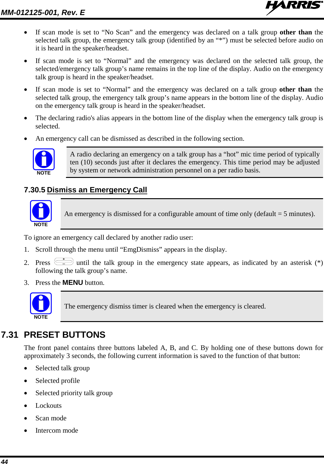
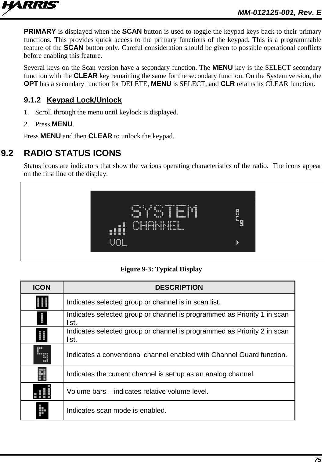
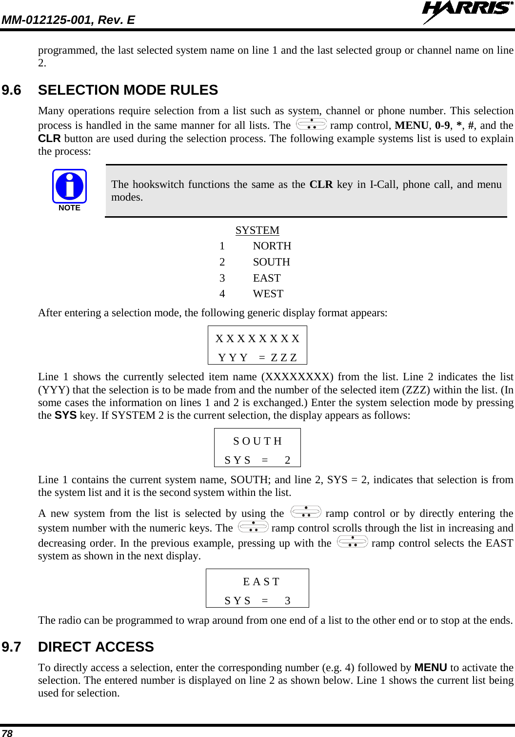
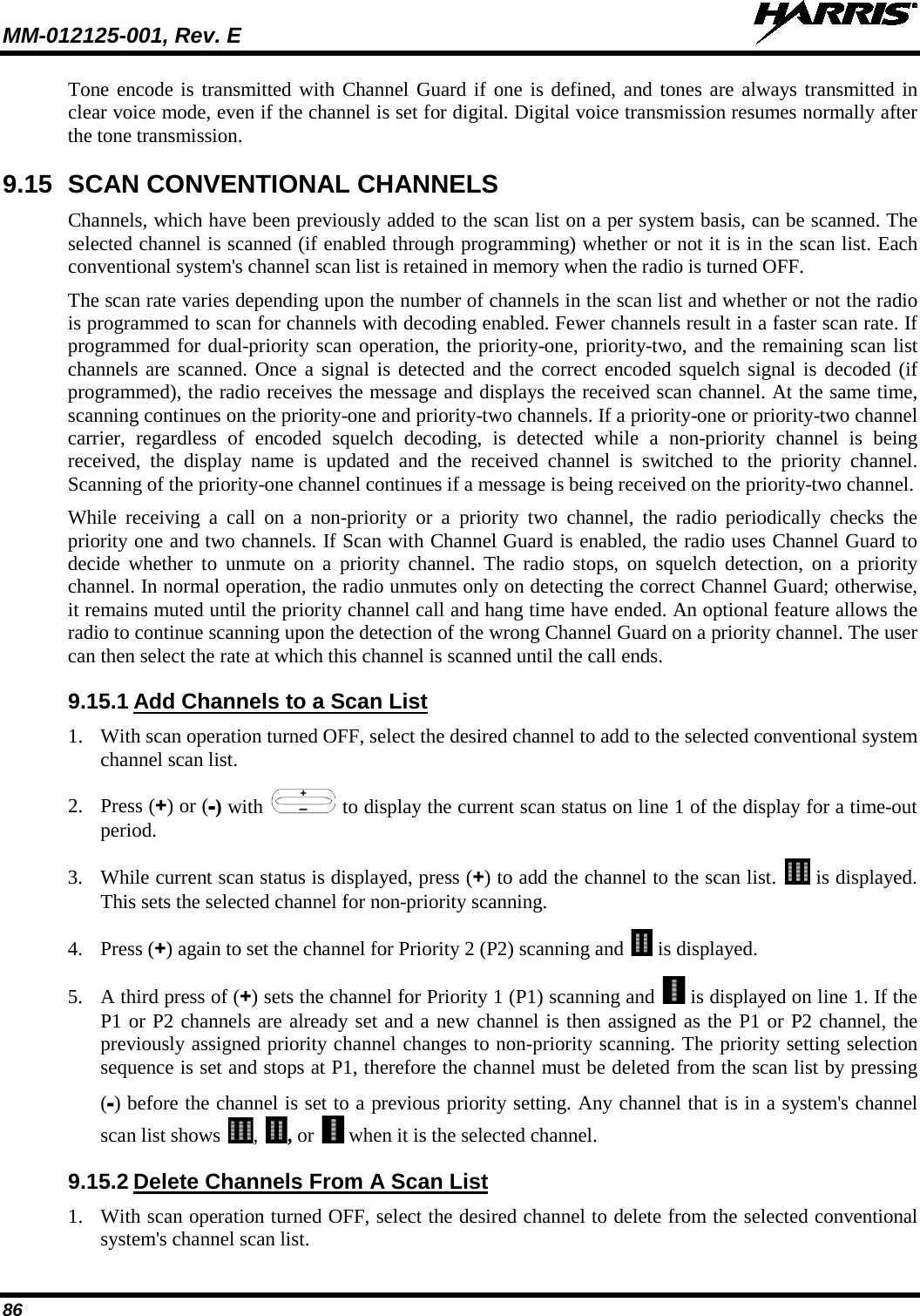
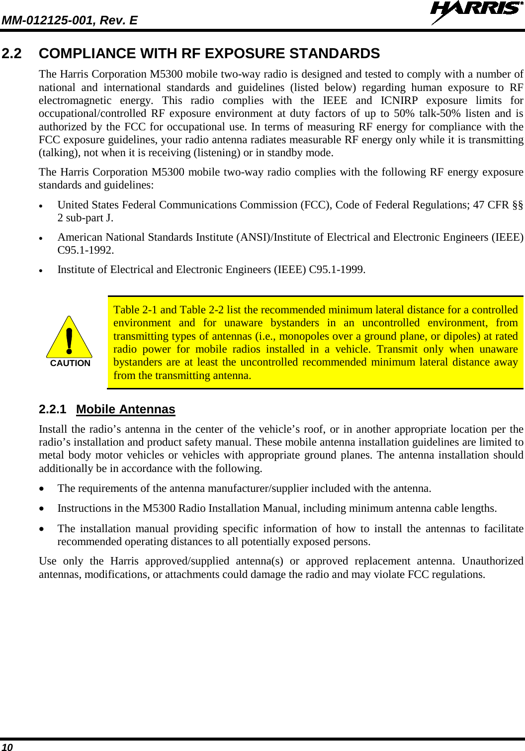
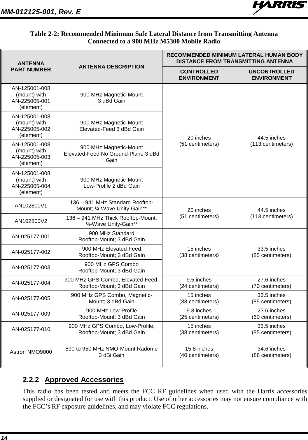
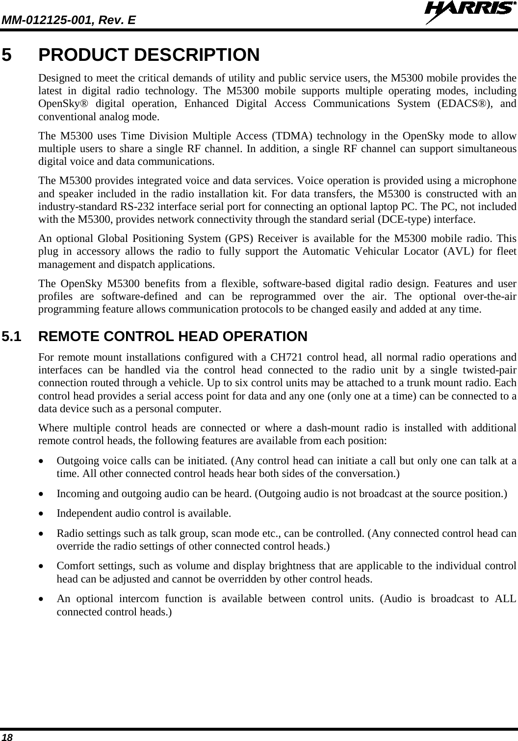
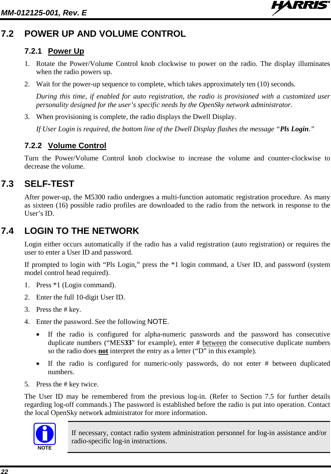
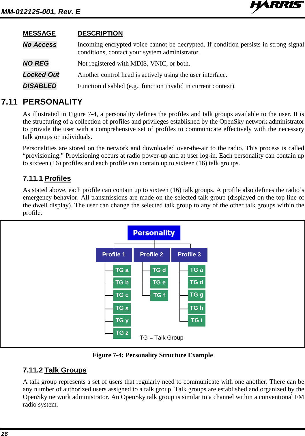
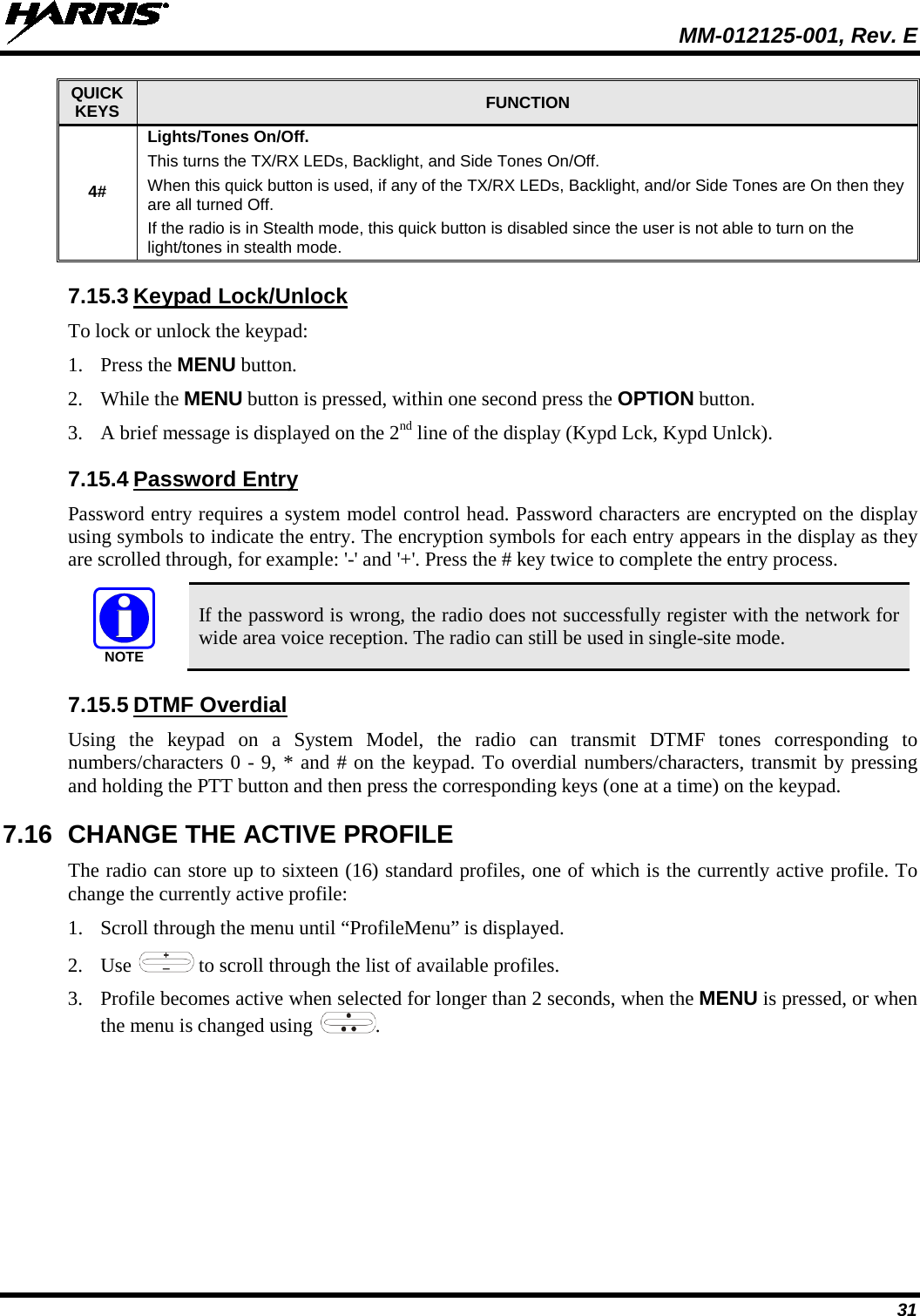
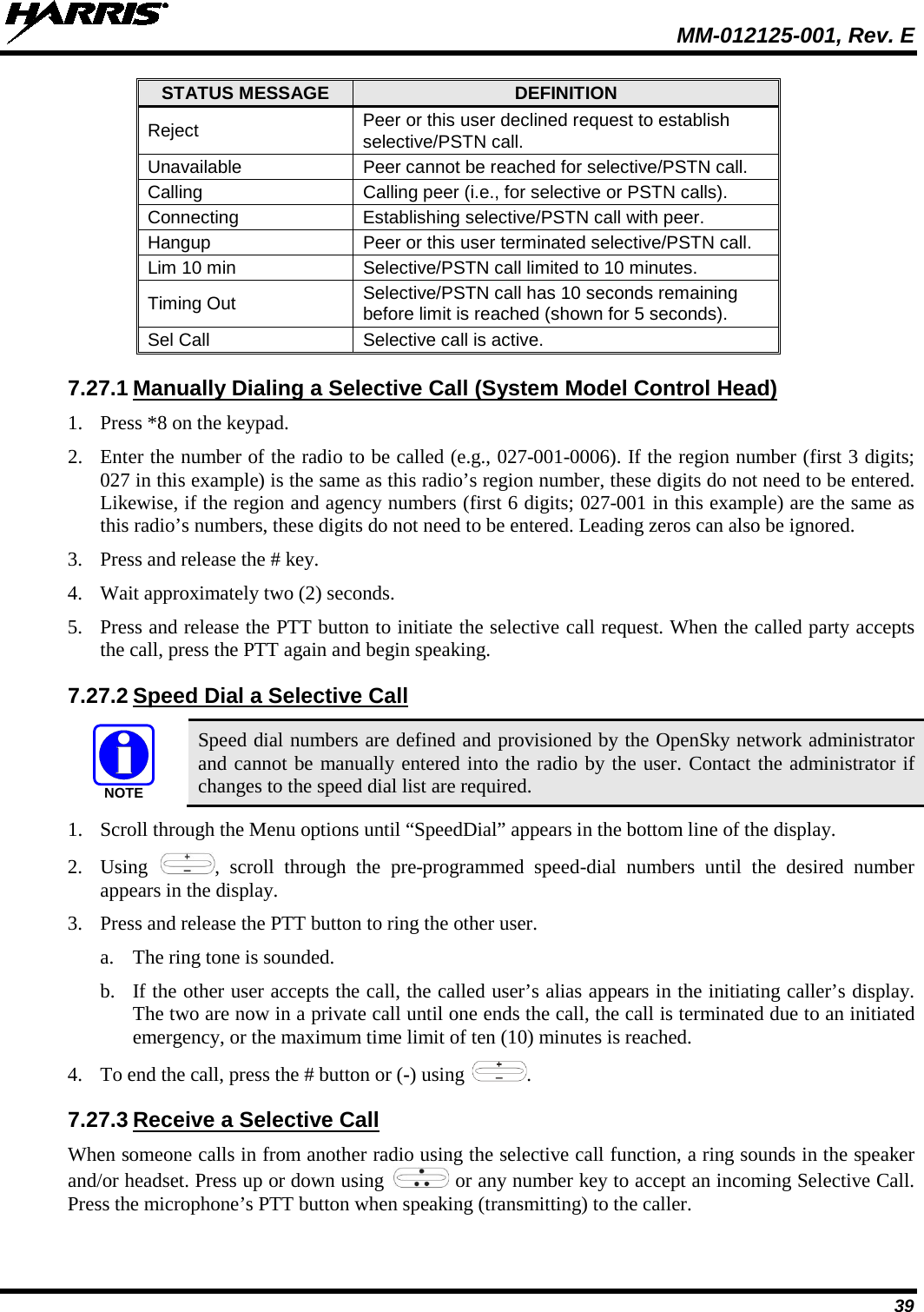
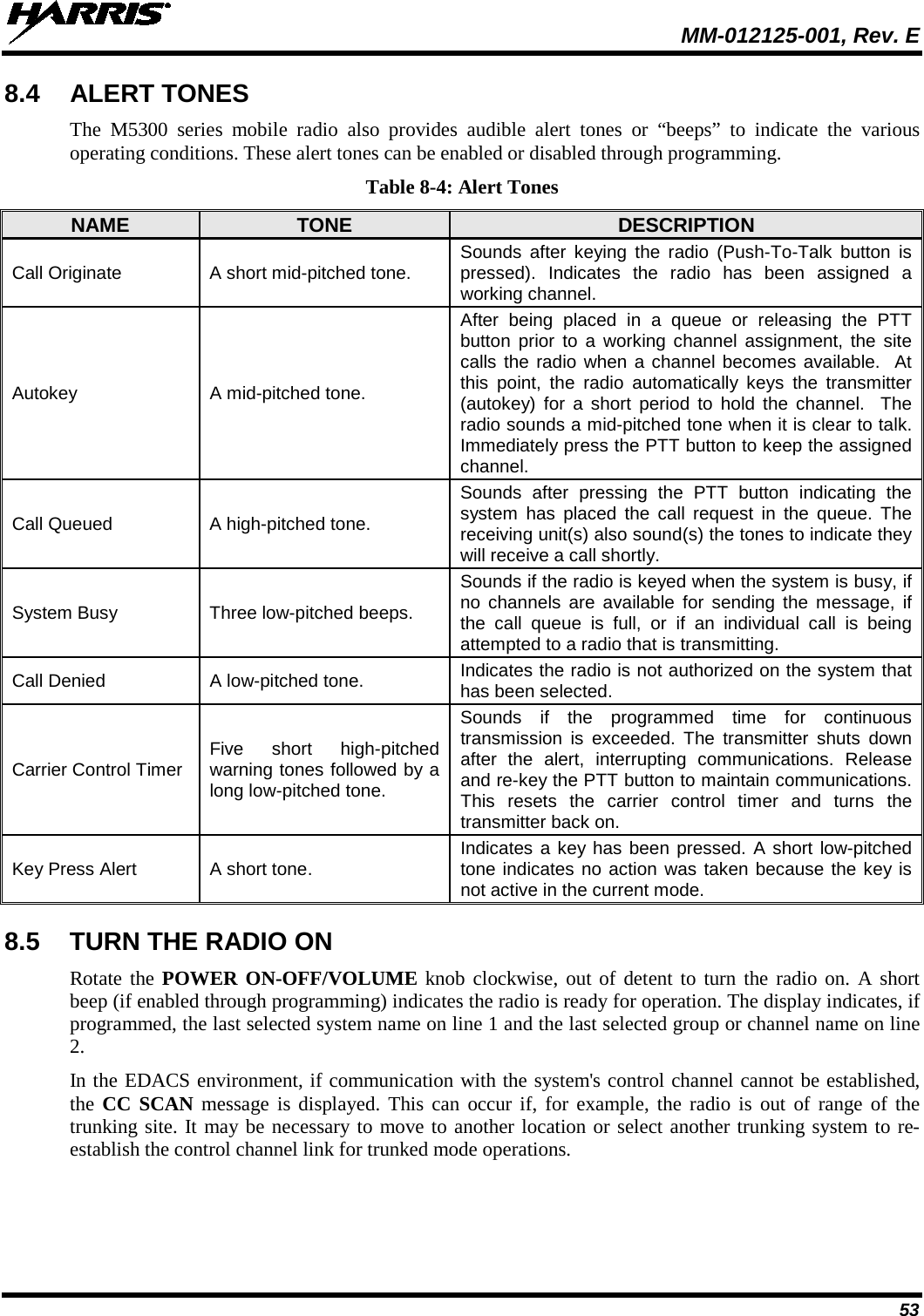
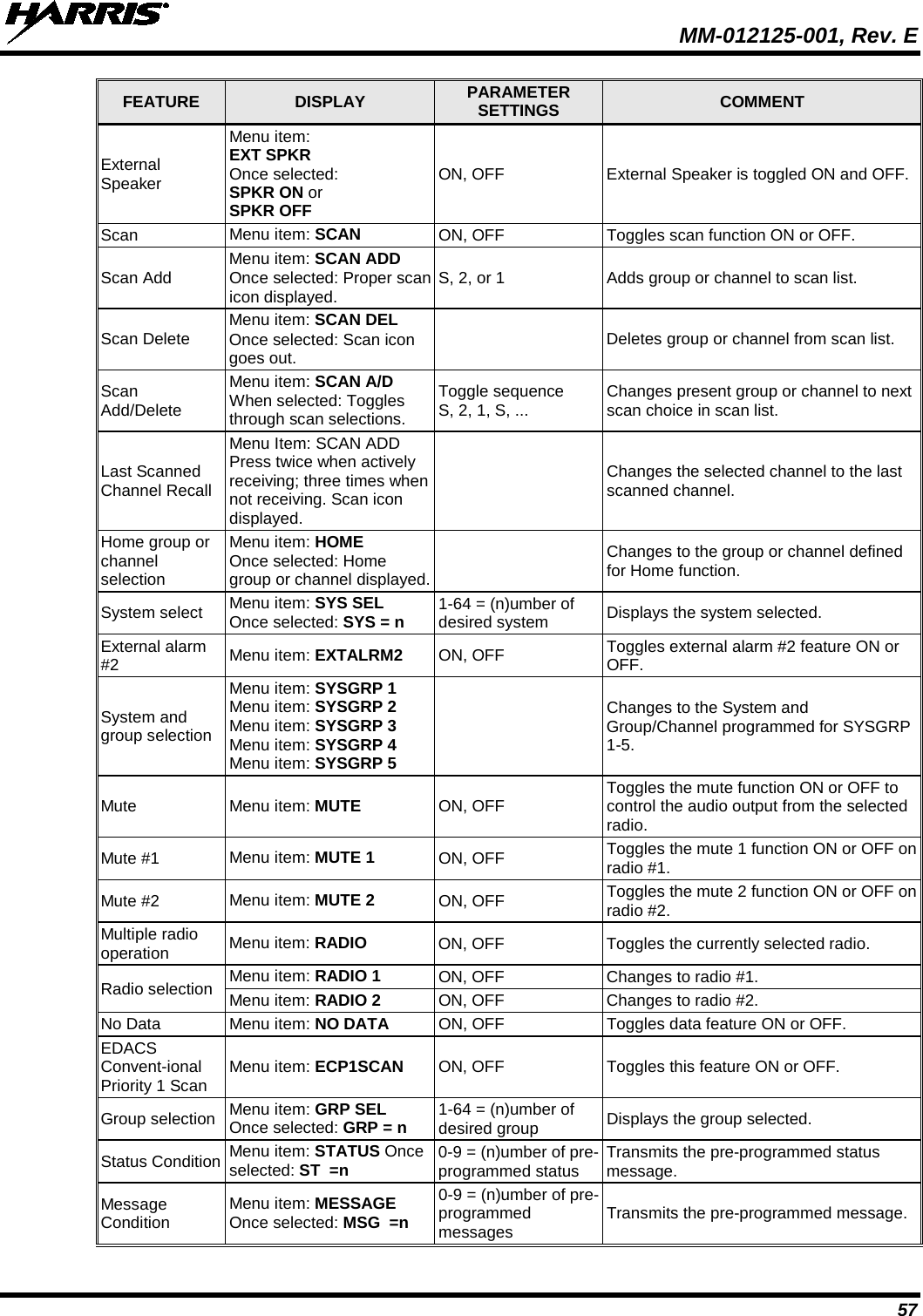
![MM-012125-001, Rev. E 45 Presets are saved and restored to/from non-volatile memory. Changing the User ID (login in as a different user) clears the presets since they are stored on a per-user basis. Changing control heads does not recall presets for the previous control head. Preset button C can be configured via programming to reboot the radio into a particular application mode. Contact your system administrator to determine if this feature is enabled in your radio. 7.32 GPS COORDINATES If equipped with the optional GPS receiver, the radio’s current latitude and longitude coordinates can be displayed using the “GPS” menu. The following procedure assumes a GPS antenna is connected to the radio and it is receiving adequate signals from GPS satellites: 1. Scroll through the menu until the “GPS” menu appears in the bottom line of the display. Current GPS coordinate latitude and longitude data continuously scrolls in the top line of the display in a degrees:minutes:seconds format. 2. Use to change to another menu. If the internal GPS receiver’s data is expired (30 minutes or more) or unavailable, the radio uses the serving base station’s coordinates [“GPS (Site)” is displayed]. The GPS Menu also indicates if the data is aged (2 minutes or more). “GPS (Aged)” is displayed. 7.33 SCENE-OF-INCIDENT MODE The Scene-of-Incident mode (SOI) is user-selectable. The SOI mode provides a local repeater function (V-TAC) with no network connection When operating in the SOI mode, the radio is disconnected from the OpenSky network. Therefore, communications with radios and dispatch personnel on the network is not possible. Enter SOI Mode Manually Entering the Channel: 1. Scroll through the menu until the Client Mode menu appears. 2. Using , scroll until SOI is displayed. 3. Press the MENU button to confirm mode selection. 4. Using , scroll until “Manual Select Chan” is displayed and press MENU. 5. Using , scroll to edit the right-most digit and press MENU to advance to the next digit. Repeat until the desired channel is entered. 6. The radio then prompts the user to edit the band. Use to edit the number assigned to the frequency band and press MENU to confirm and enter the SOI mode. Use the Client Mode menu to return to normal operation (Network Mode). The personality and profile in use at the time the radio entered SOI mode is restored. NOTENOTECAUTION](https://usermanual.wiki/HARRIS/TR-0049-E.Operators-Manual/User-Guide-1331923-Page-45.png)
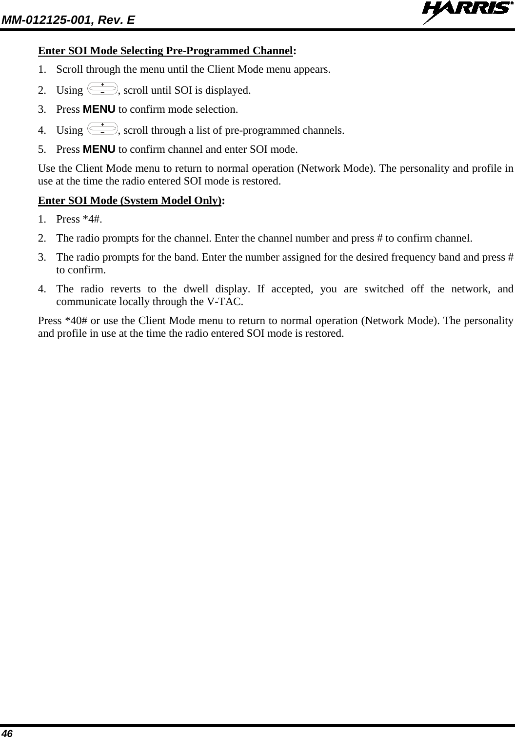
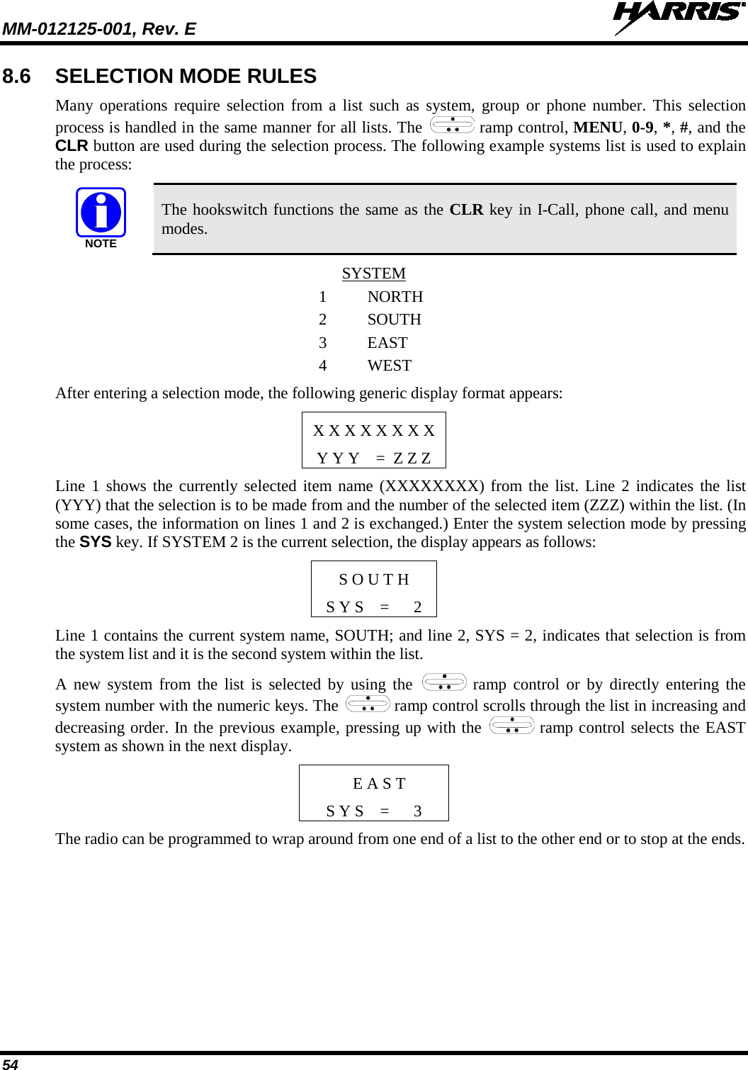
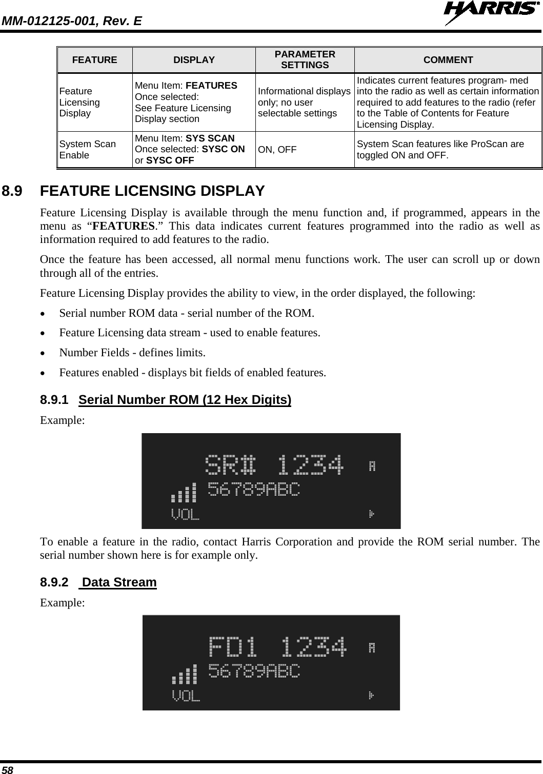
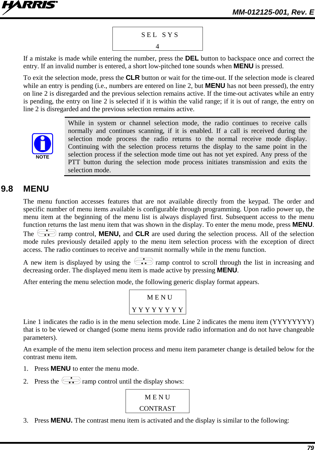
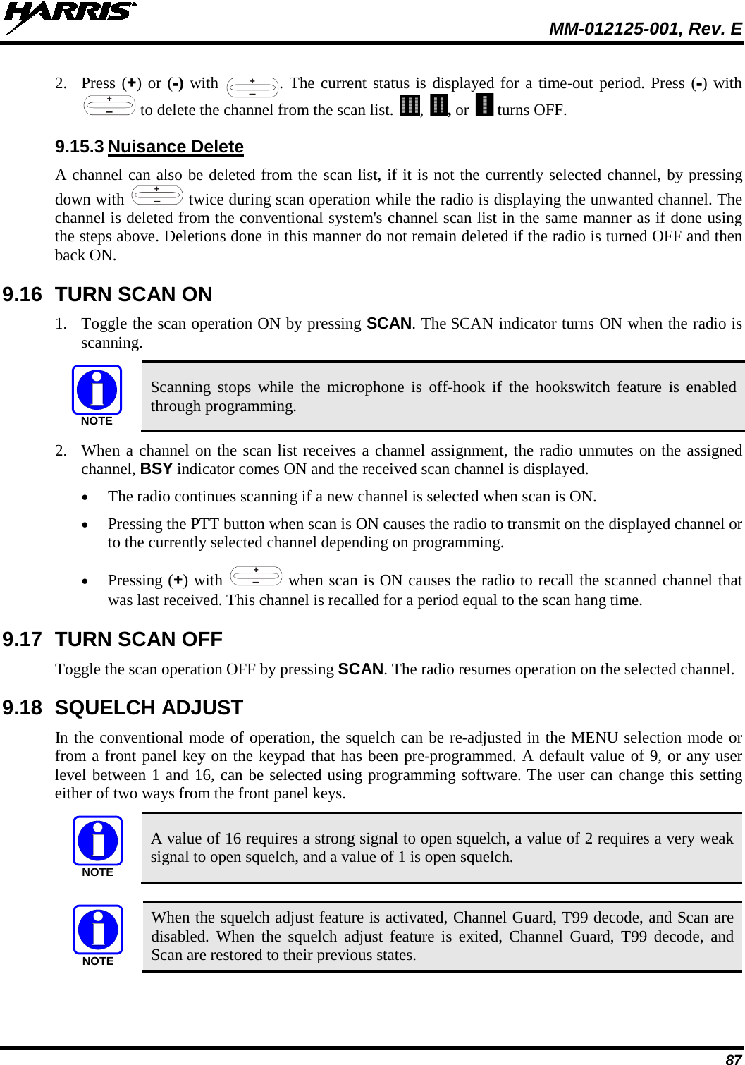
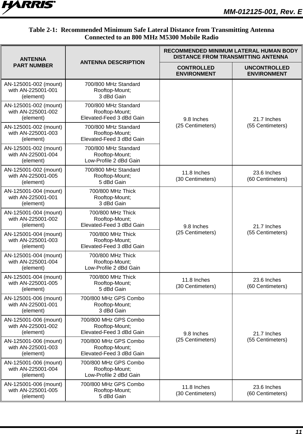
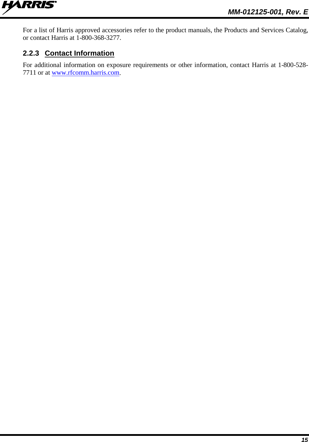
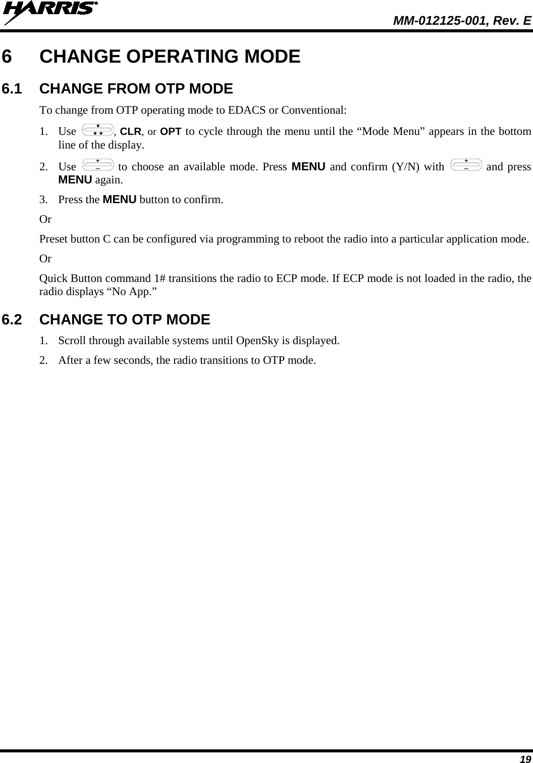
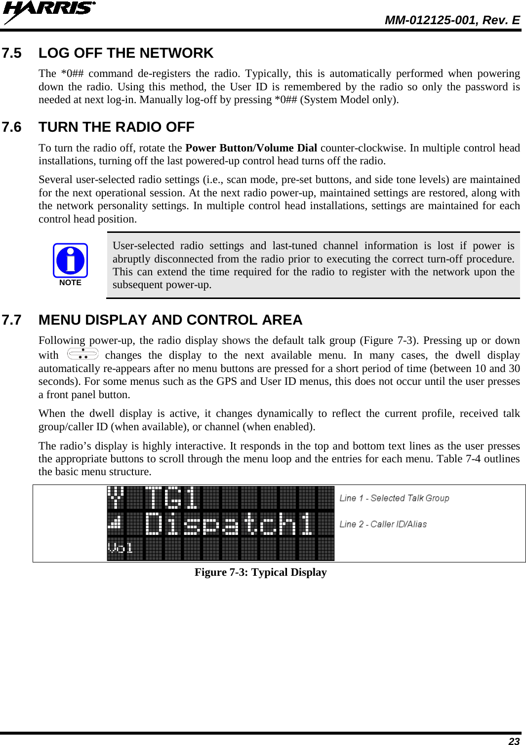
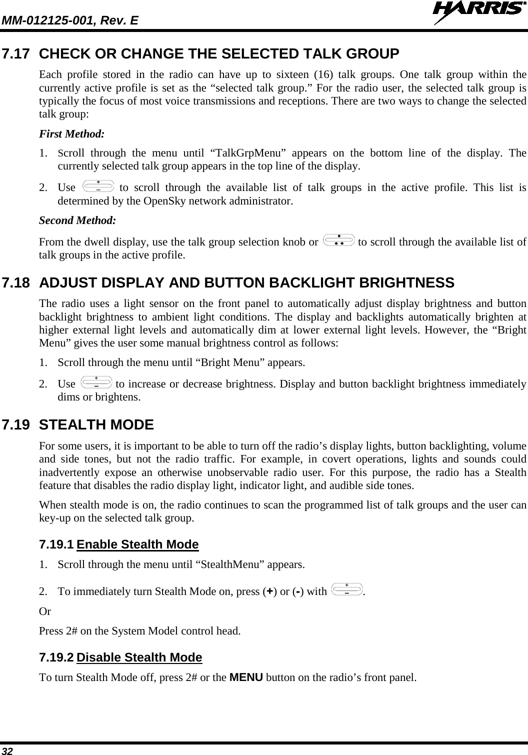
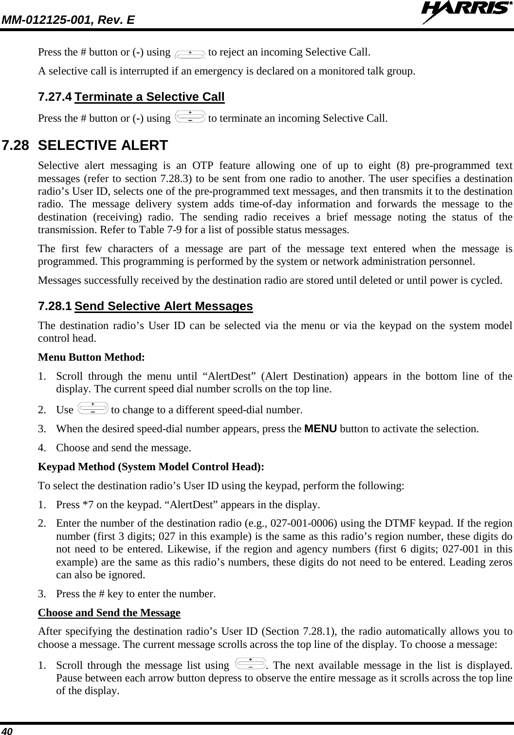
![MM-012125-001, Rev. E 63 8.16 SYSTEM SCAN OPERATION The radio can be programmed with the following System Scan features. These features are automatically enabled upon radio power up. A key or menu option is also defined to allow the System Scan features to be toggled during radio operation. This is covered in the Menu Selection and Pre-Programmed Keypad Key sections. The System Scan state is maintained through system changes but defaults to ON at power up. 8.16.1 Wide Area System Scan The M5300 Series mobile radio can be programmed for wide area system scan operation for multi-site applications. Upon the loss of the currently selected system's control channel, radios can be programmed to automatically scan the control channels of other systems. If a new control channel is found, the radio switches to the new system and sound an alert tone. 8.16.2 ProScan The radio can be programmed for ProScan™ system scan operation for multi-site applications depending on the version of radio flash code. ProScan provides the radio with the ability to select a new system for the radio to communicate on, when the selected system drops below a predefined level. This is accomplished by enabling each radio to analyze the signal quality of its current control channel and compare it with the signal quality of the control channel for each site in its adjacency scan list. (The signal quality metric used for the ProScan algorithm is based on a combination of both Received Signal Strength Indicator [RSSI] and Control Channel Verification [CCV] measurements.) When the selected system’s signal quality level degrades below a pre-programmed level, the radio begins to look for a better control channel. Once a control channel that exceeds the pre-programmed parameters is found, the radio changes to the new system and emit a tone. If the control channel is completely lost, the radio enters Wide Area System Scanning and searches the programmed adjacent systems until a suitable control channel is found. 8.16.3 Priority System Scan The radio can also be programmed for Priority System Scan. (To ensure that this feature operates correctly, the control channel of the priority system must be located on channel one unless you are using the ProScan algorithm.) The priority system is the desired or preferred system. While receiving the control channel of the selected system, the radio periodically leaves the selected system and searches for the control channel of the priority system at a programmable rate. The programmable rate is defined by the value in the Priority Scan Time control, (unless the ProScan algorithm is enabled as explained below). This priority scan timer is reset each time the PTT button is pressed or when a call is received. If the priority system control channel is found, or meets the predefined ProScan criteria, the radio automatically switches to the priority system. 8.16.4 When Wide Area System Scan is Enabled If the radio cannot find the control channel of the selected system and begins Wide Area System Scan (WA Scan), the radio only scans for the priority system control channel if the priority system is in the WA Scan list. 8.16.5 When ProScan is Enabled The radio monitors the priority system and switches to the priority system if the priority system meets the criteria defined in the “ProScan Options” dialog box. If ProScan is enabled, the rate at which the radio scans for the priority system is defined by the System Sample Time control.](https://usermanual.wiki/HARRIS/TR-0049-E.Operators-Manual/User-Guide-1331923-Page-63.png)