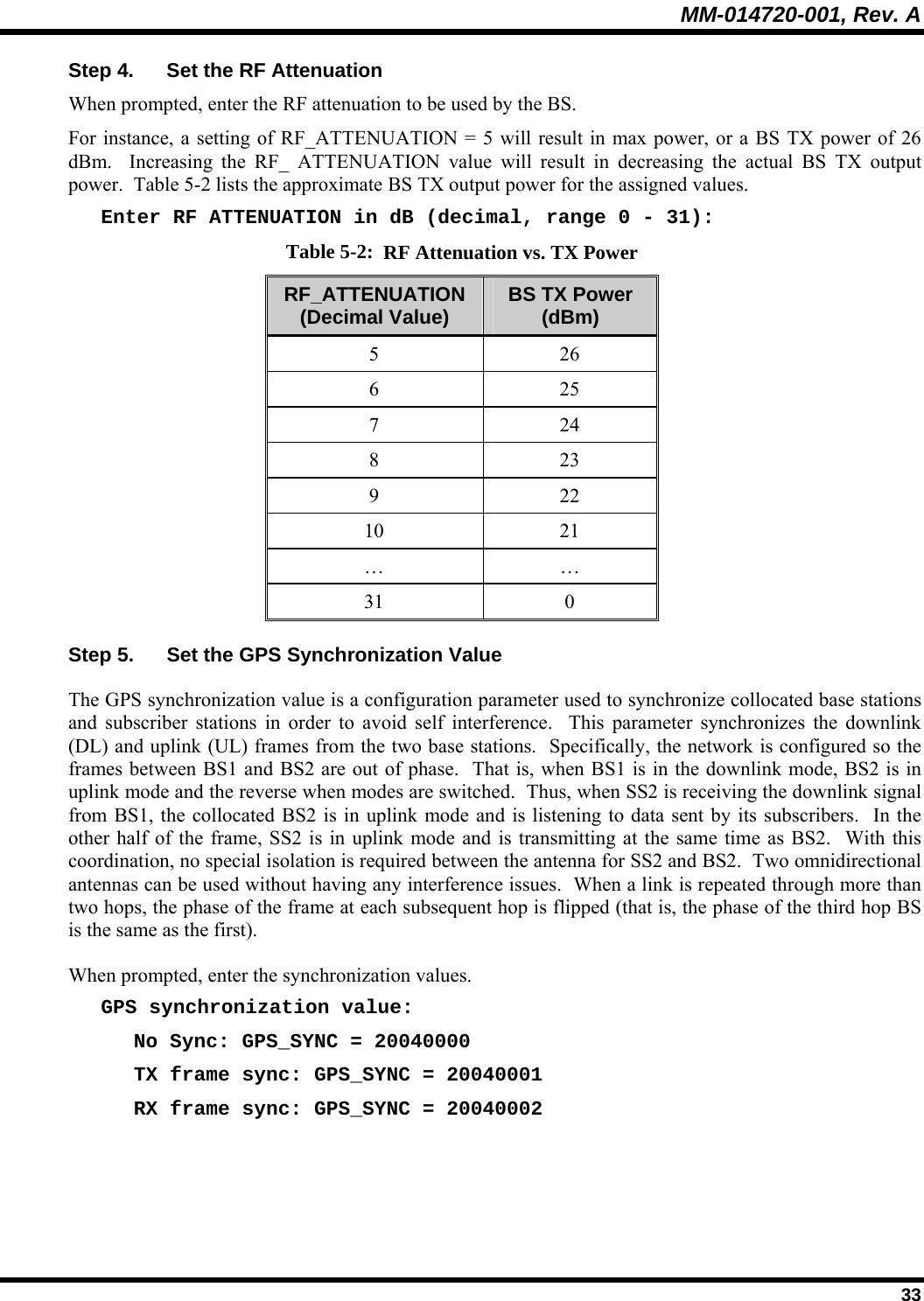
HARRIS VIDA-BB-CL VIDA Broadband High Power Client User Manual TYPE CERTIFICATION REPORT
Harris Corporation VIDA Broadband High Power Client TYPE CERTIFICATION REPORT
UserManual.wiki
>
HARRIS
>
VIDA-BB-CL User Manual
>
Manual 1
Contents
1.
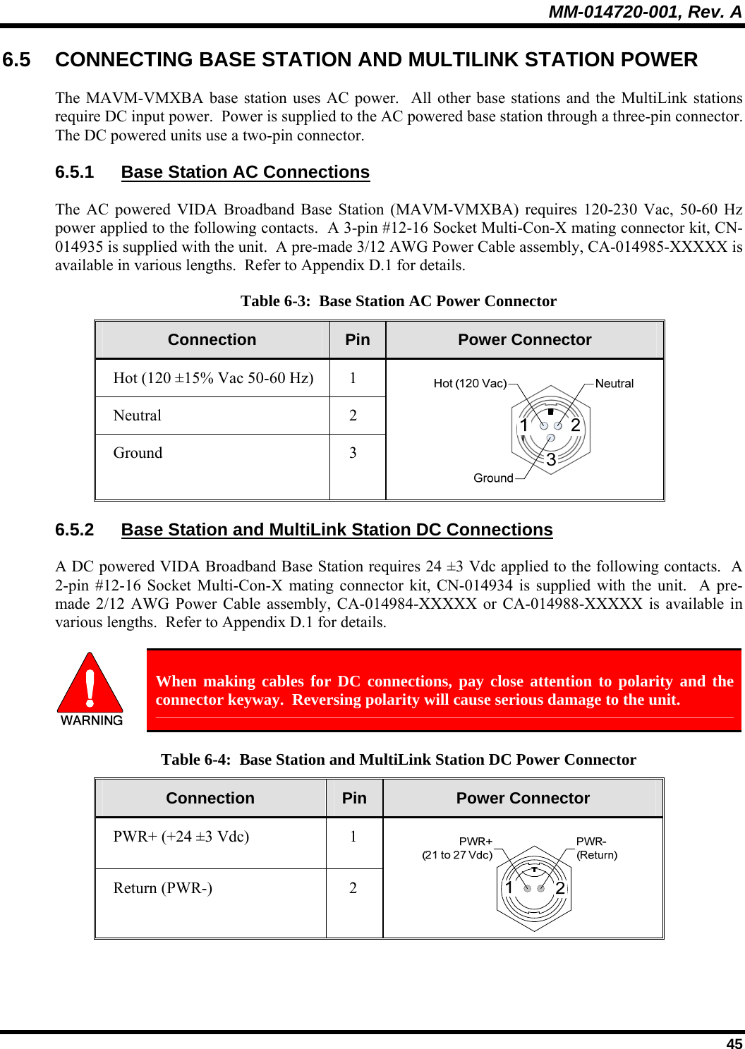
Manual
2.
Manual 1
3.
Manual 2
Manual 1
Navigation menu
Upload a User Manual
Namespaces
Wiki Guide
HTML
PDF
Info
Views
User Manual
Discussion / Help
Navigation