HARRIS VIDA-BB-CL VIDA Broadband High Power Client User Manual TYPE CERTIFICATION REPORT
Harris Corporation VIDA Broadband High Power Client TYPE CERTIFICATION REPORT
UserManual.wiki
>
HARRIS
>
VIDA-BB-CL User Manual
>
Manual 2
Contents
1.
Manual
2.
Manual 1
3.
Manual 2
Manual 2
Navigation menu
Upload a User Manual
Namespaces
Wiki Guide
HTML
PDF
Info
Views
User Manual
Discussion / Help
Navigation

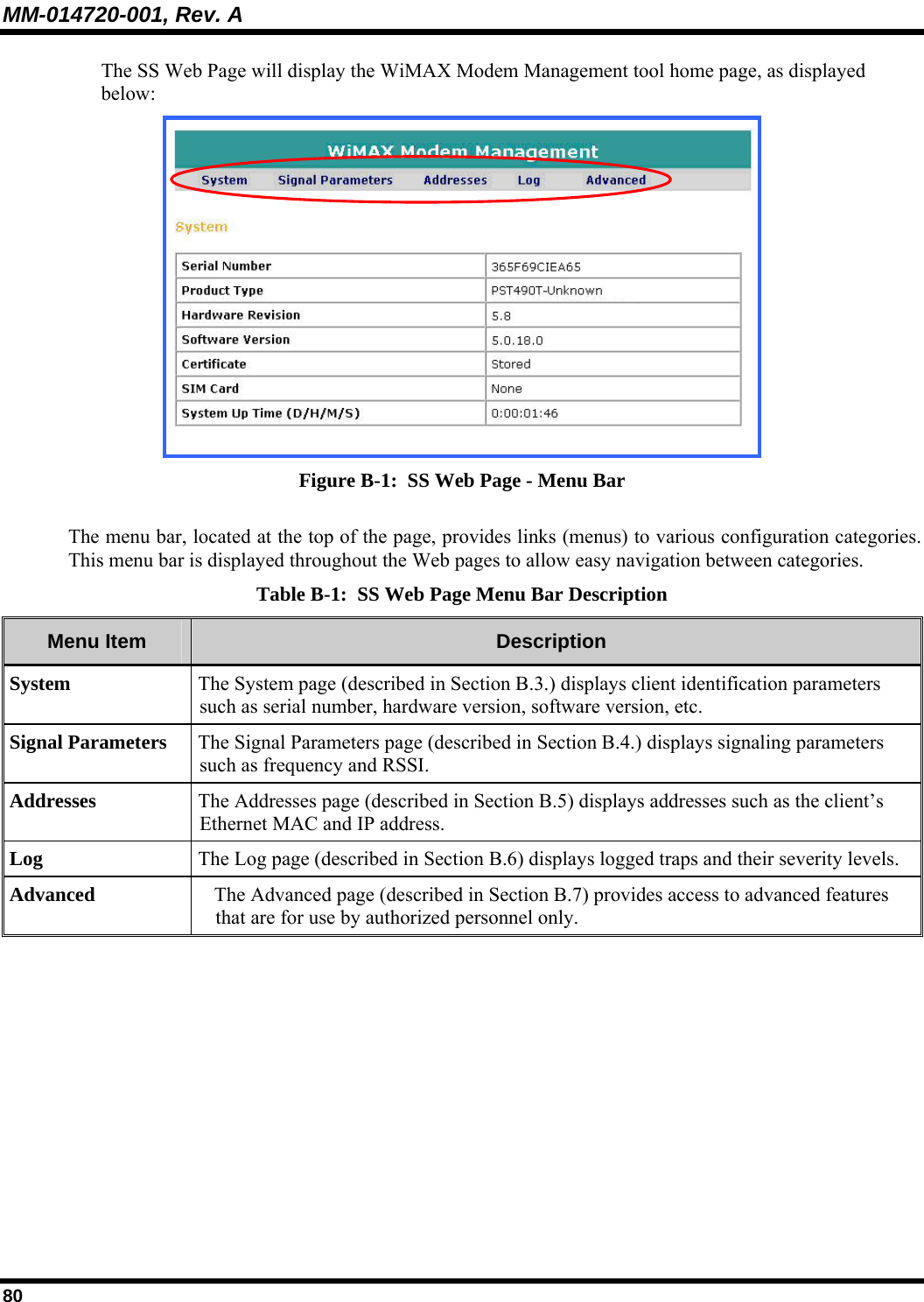
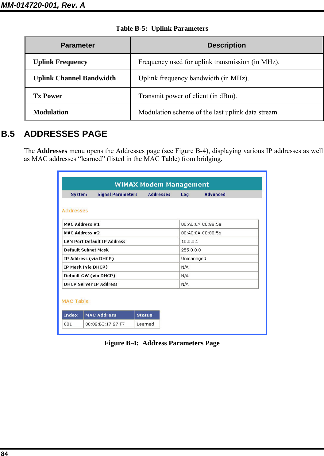
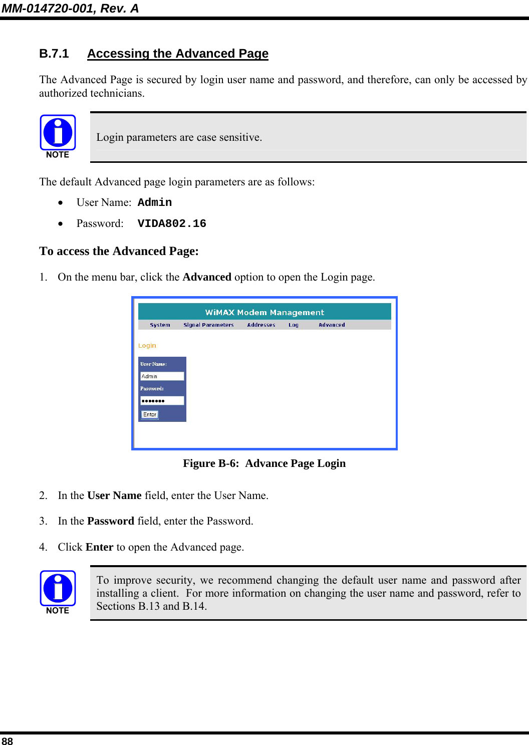
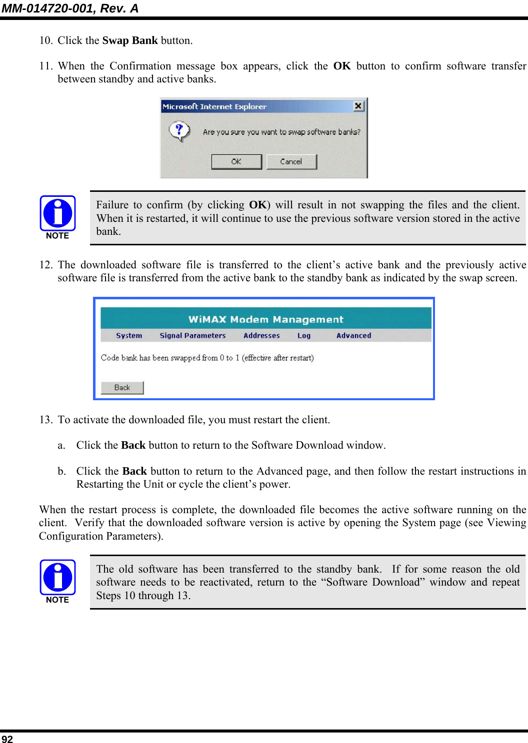
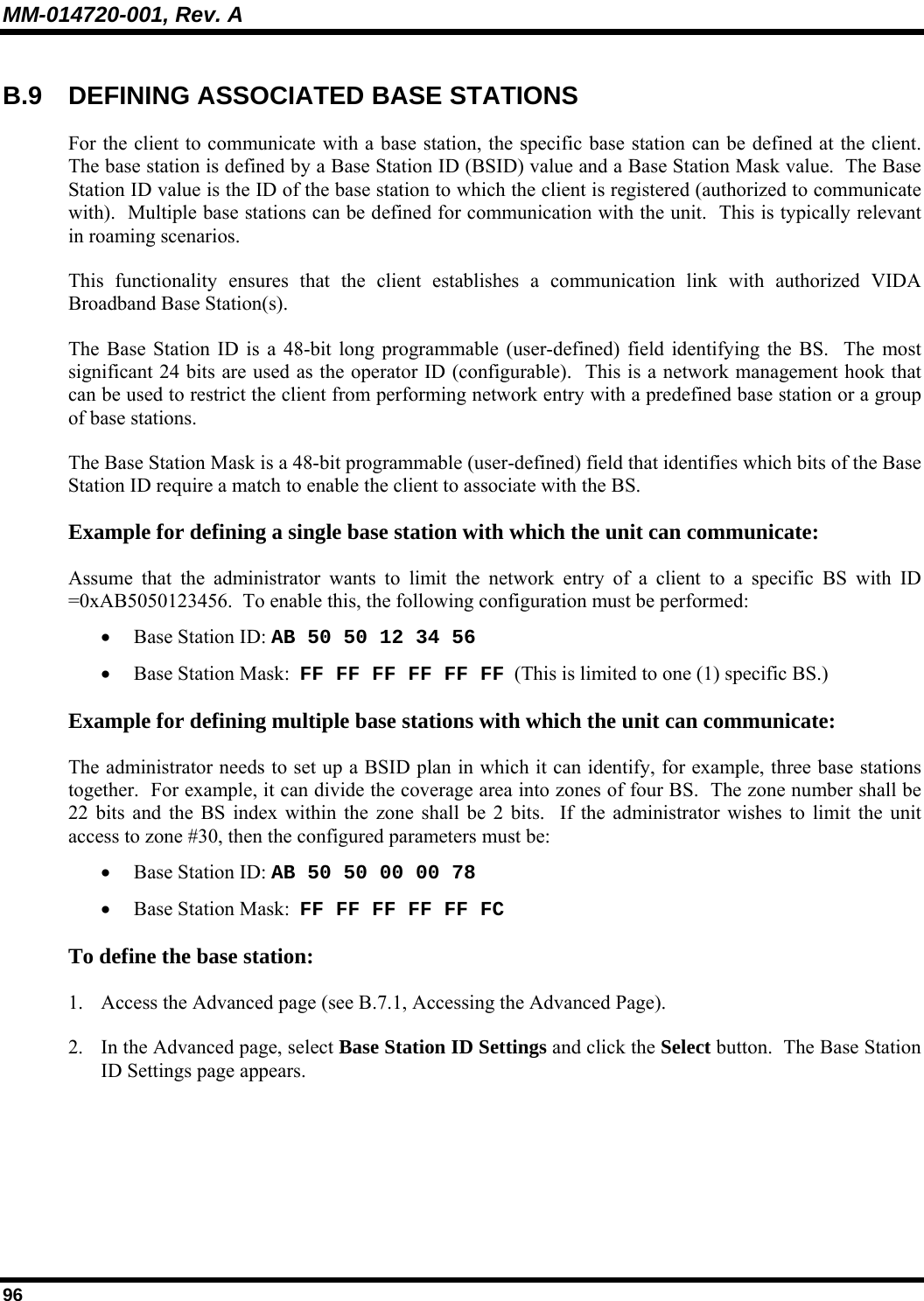

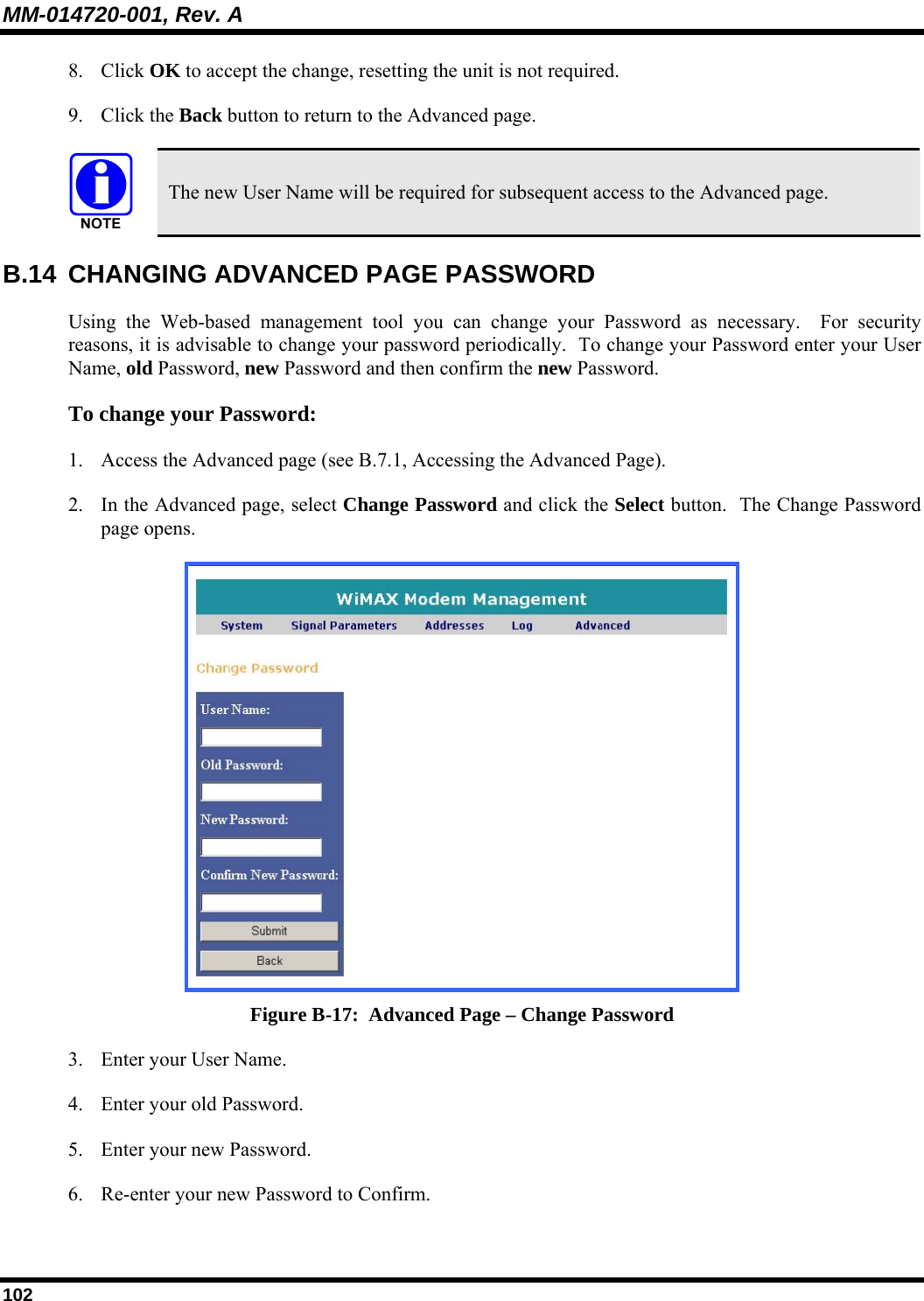
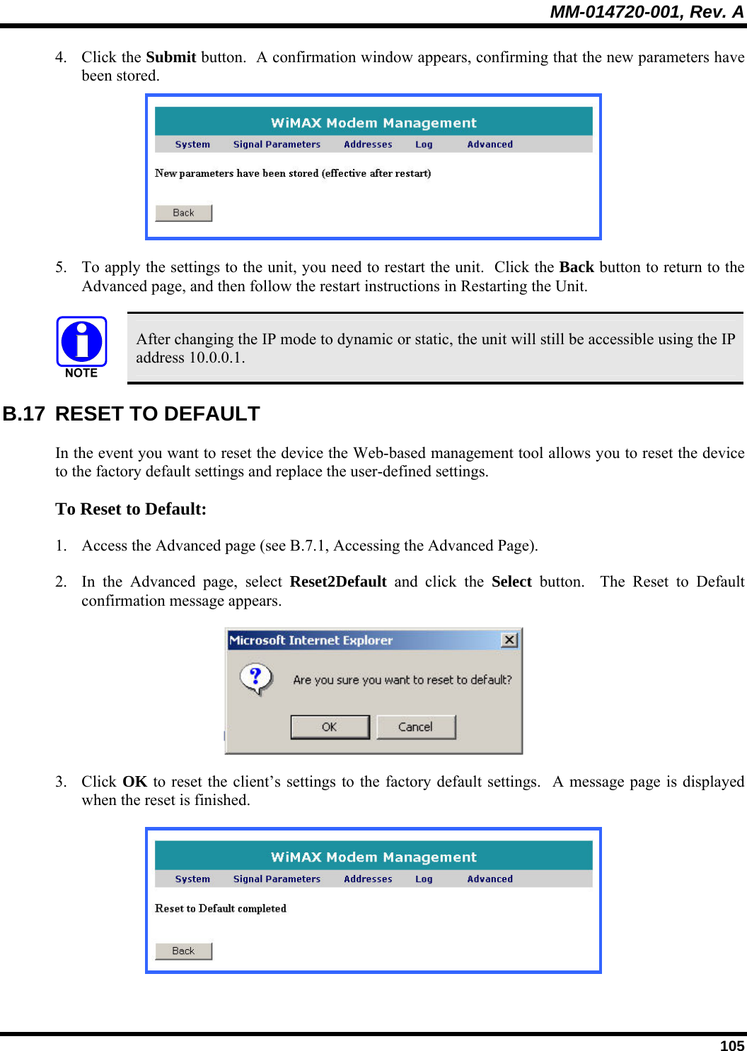


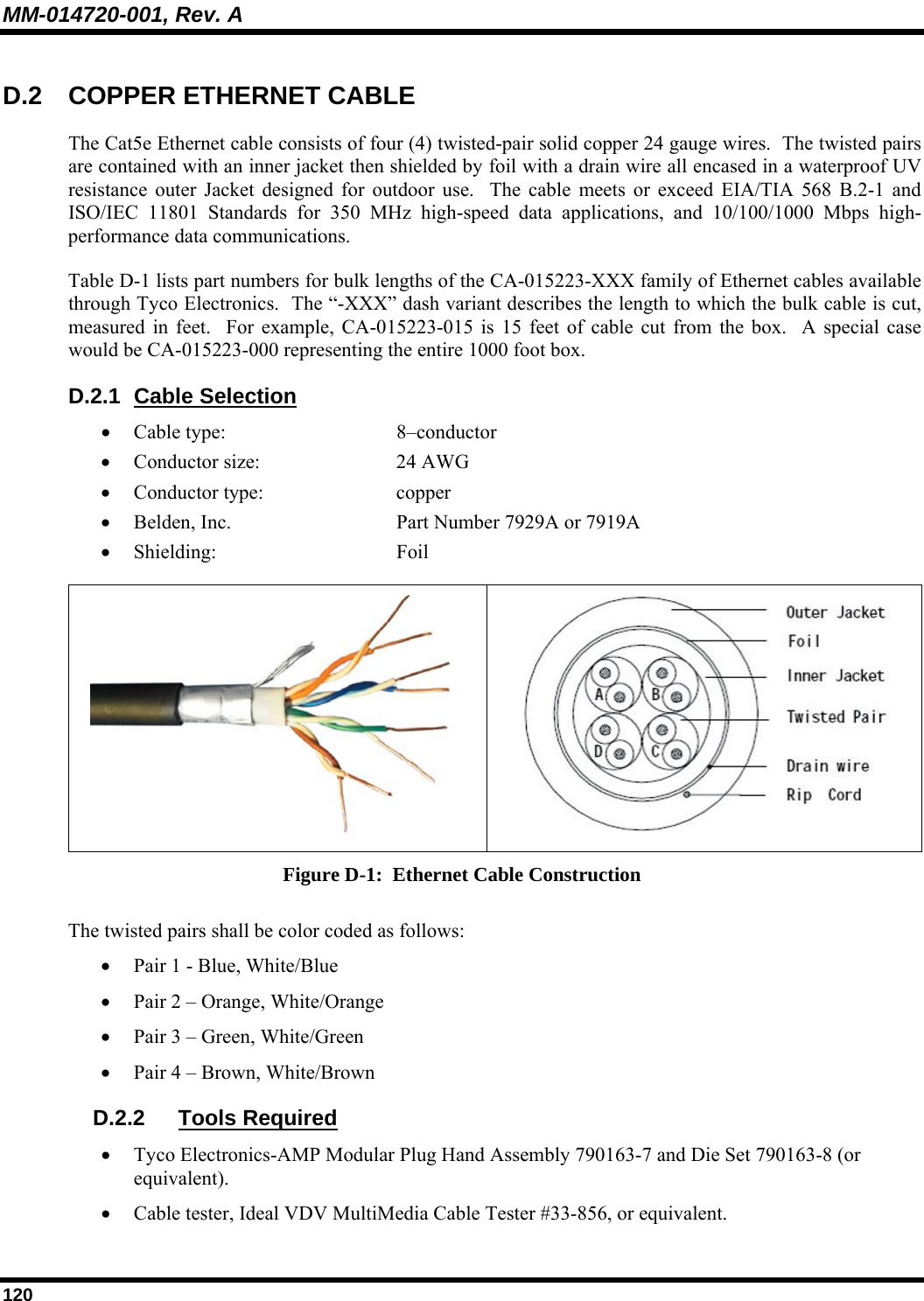
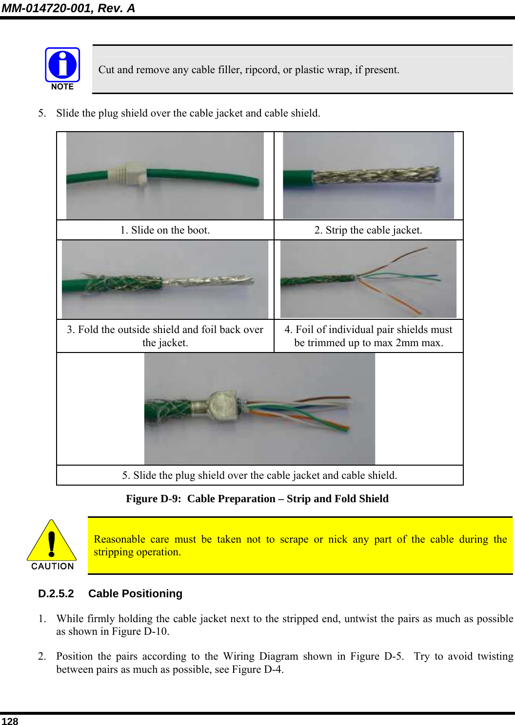
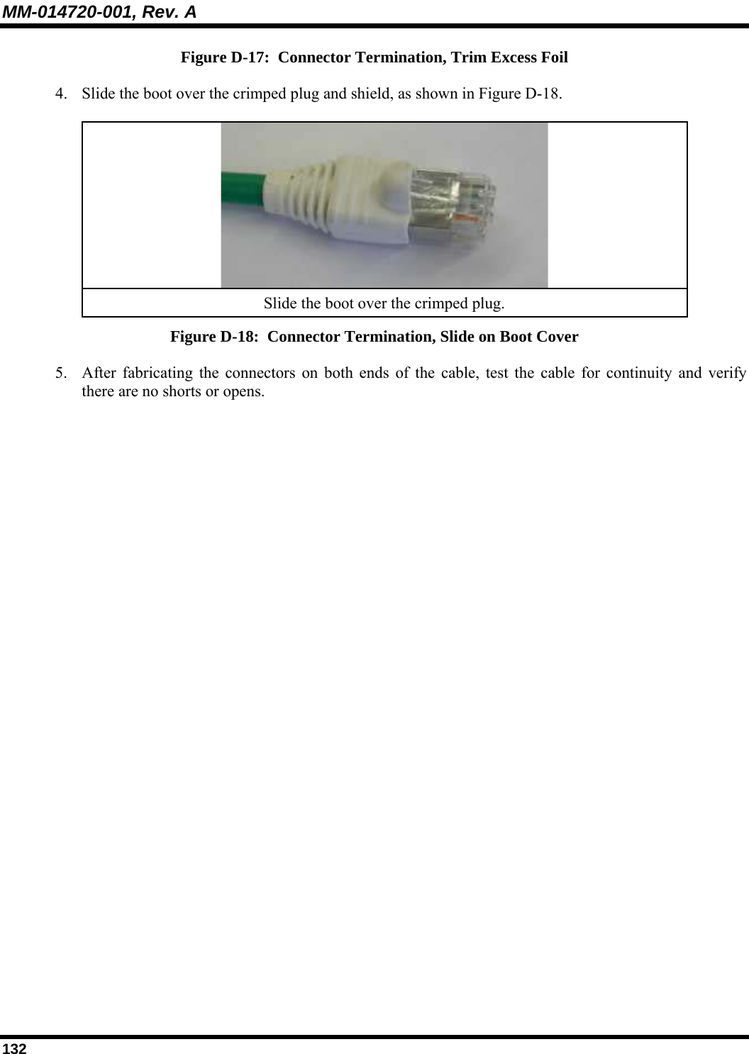
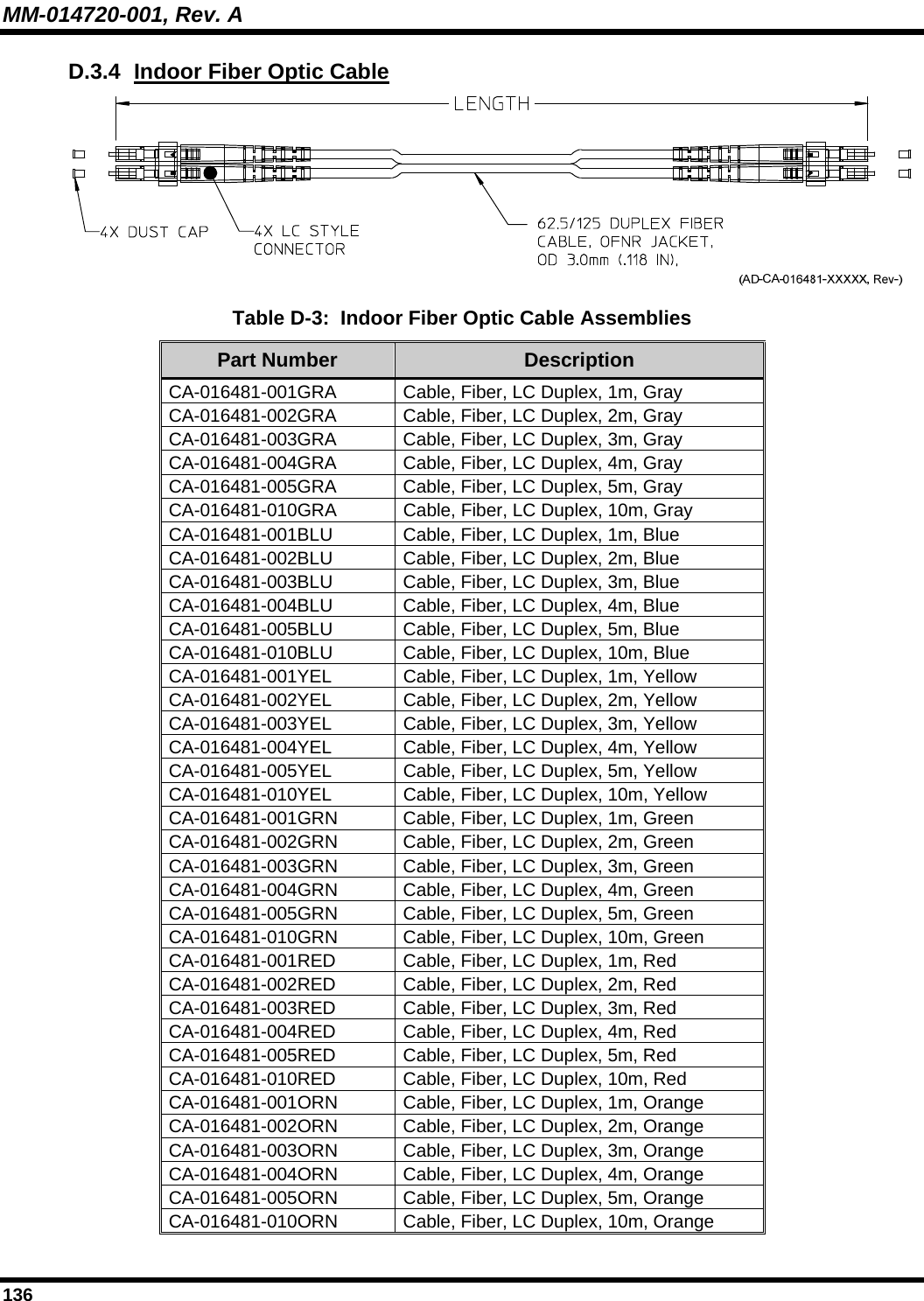
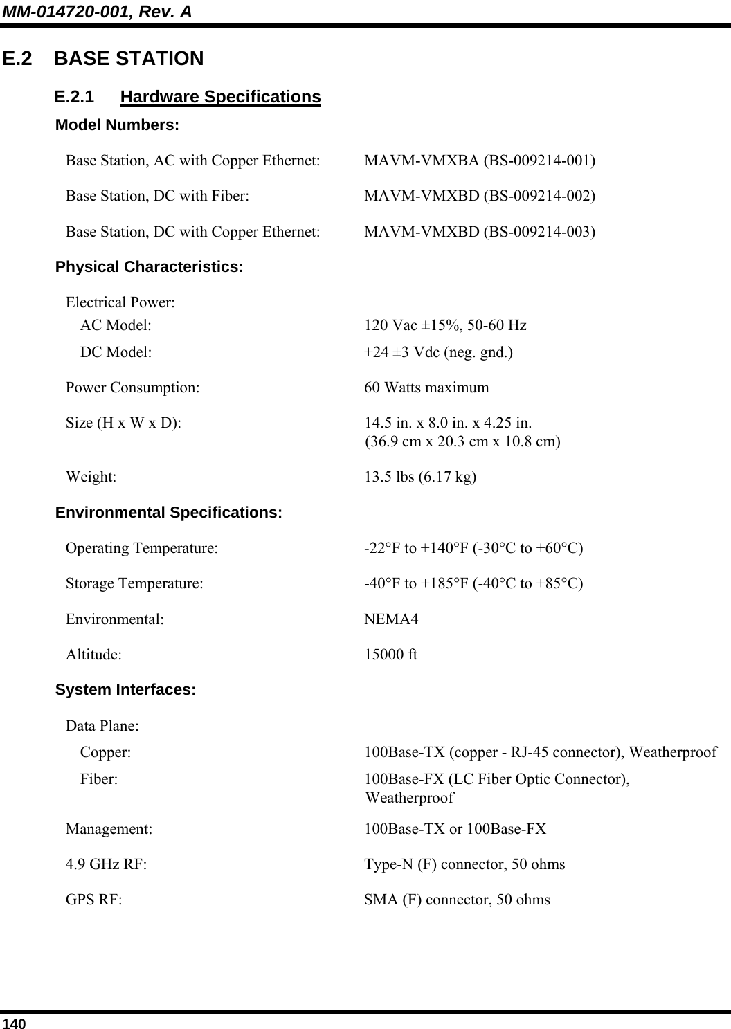
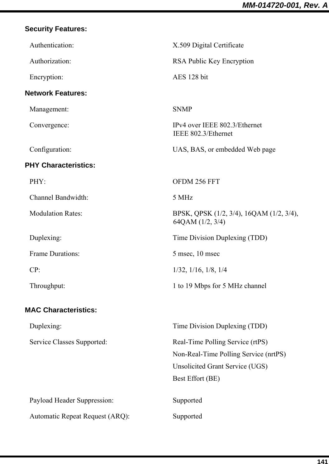
![MM-014720-001, Rev. A 125 Figure D-6: Termination Requirements 4. The RJ-45 plug must be terminated to the cable according to the instructions included with the tooling. D.2.4.2 Assembly Assemble the RJ-45 connector into the plug assembly using the following procedures: 1. Align the locking tab of the RJ-45 plug with the wide slot at the front (end opposite the cable fitting) of the plug assembly. See Figure D-7, Detail A. 2. Depress the locking tab, and insert the RJ-45 plug into the plug assembly. Gently pull the cable until the RJ-45 plug is fully seated. There should be approximately 12.7 mm [.50 in.] of the RJ-45 plug protruding from the front of the plug assembly. See Figure D-7, Detail B.](https://usermanual.wiki/HARRIS/VIDA-BB-CL.Manual-2/User-Guide-1074976-Page-47.png)
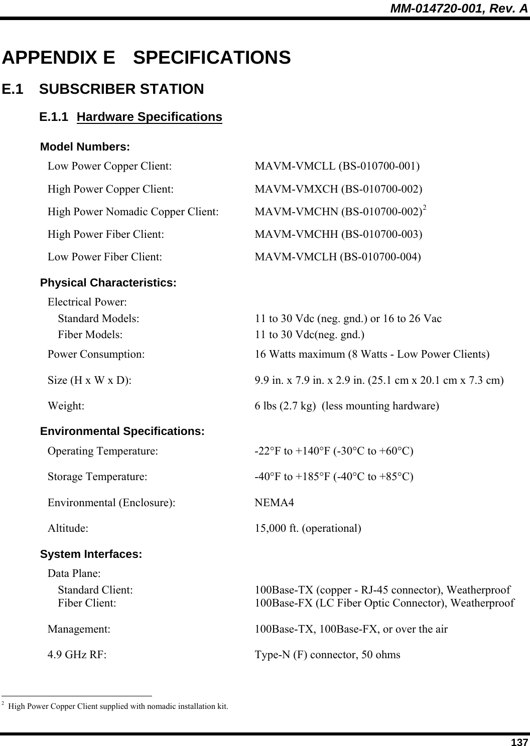
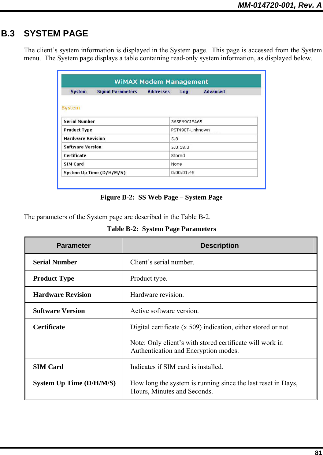
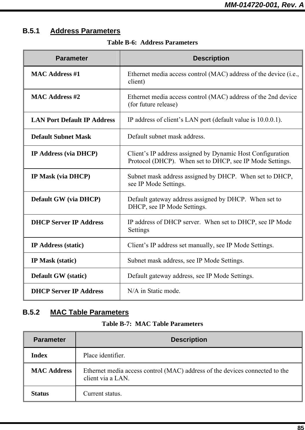
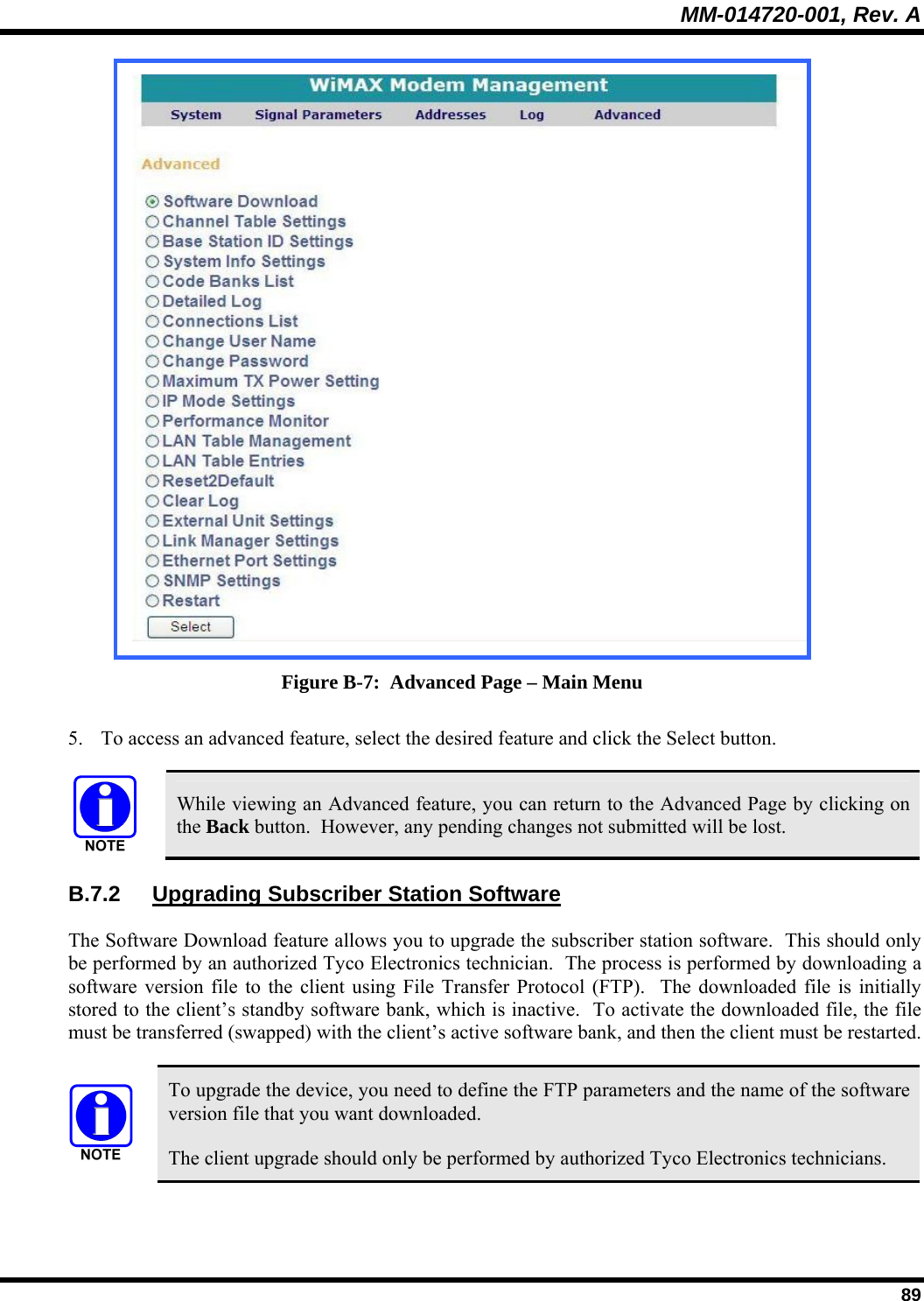
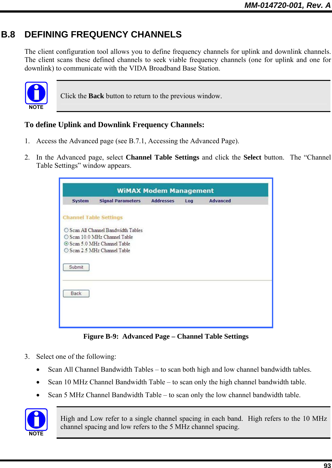
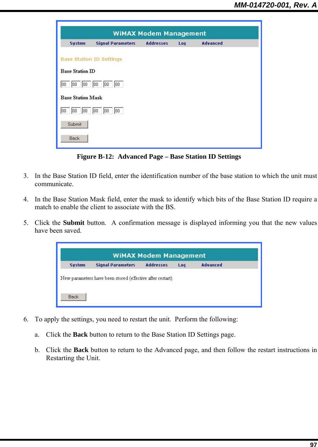
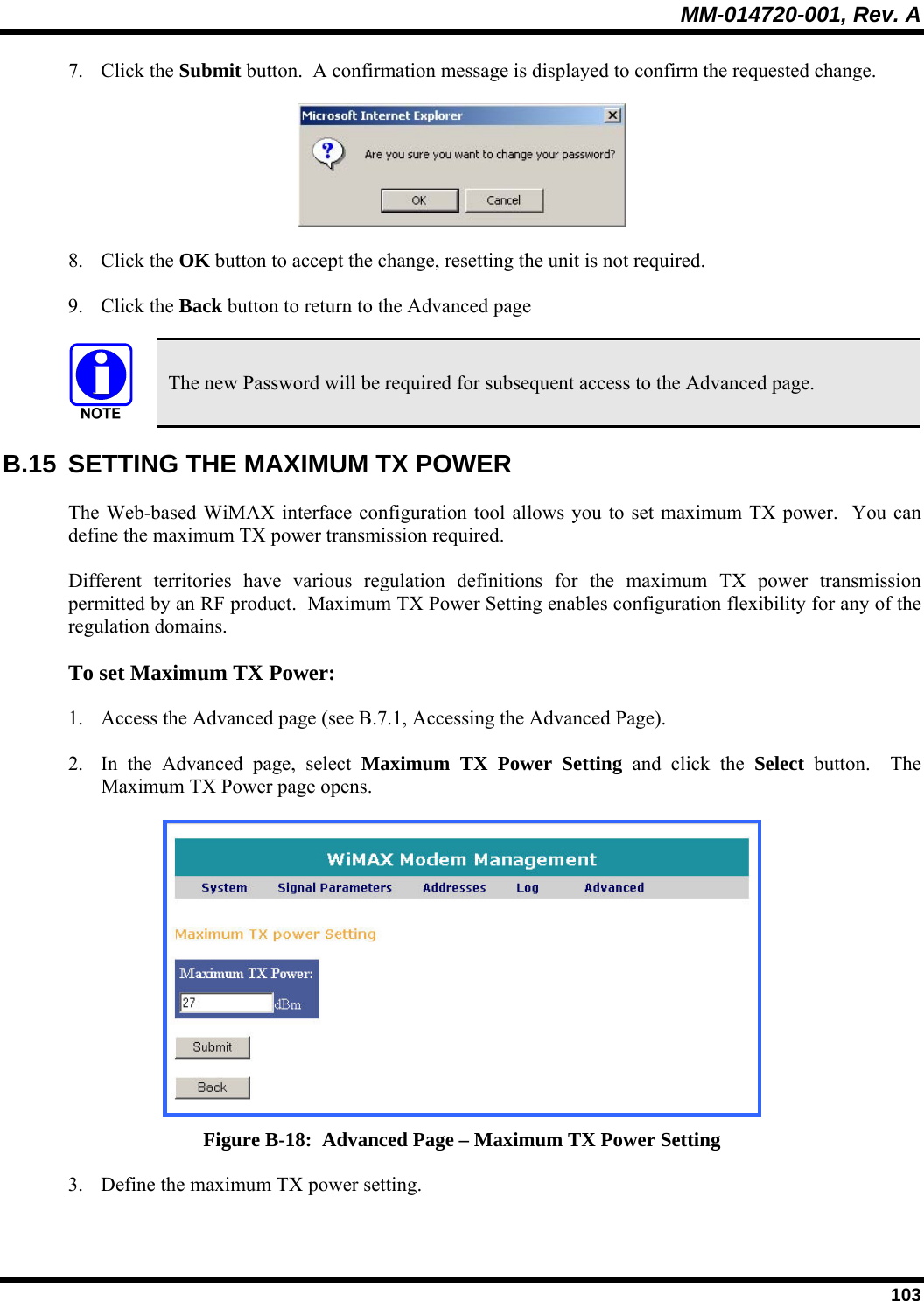
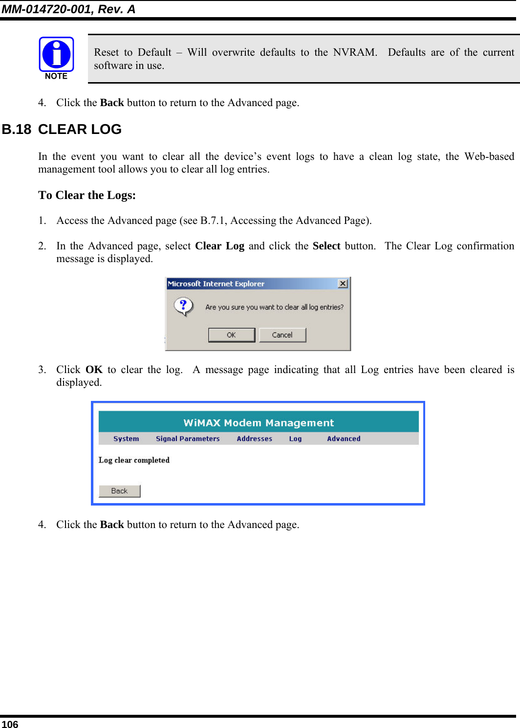
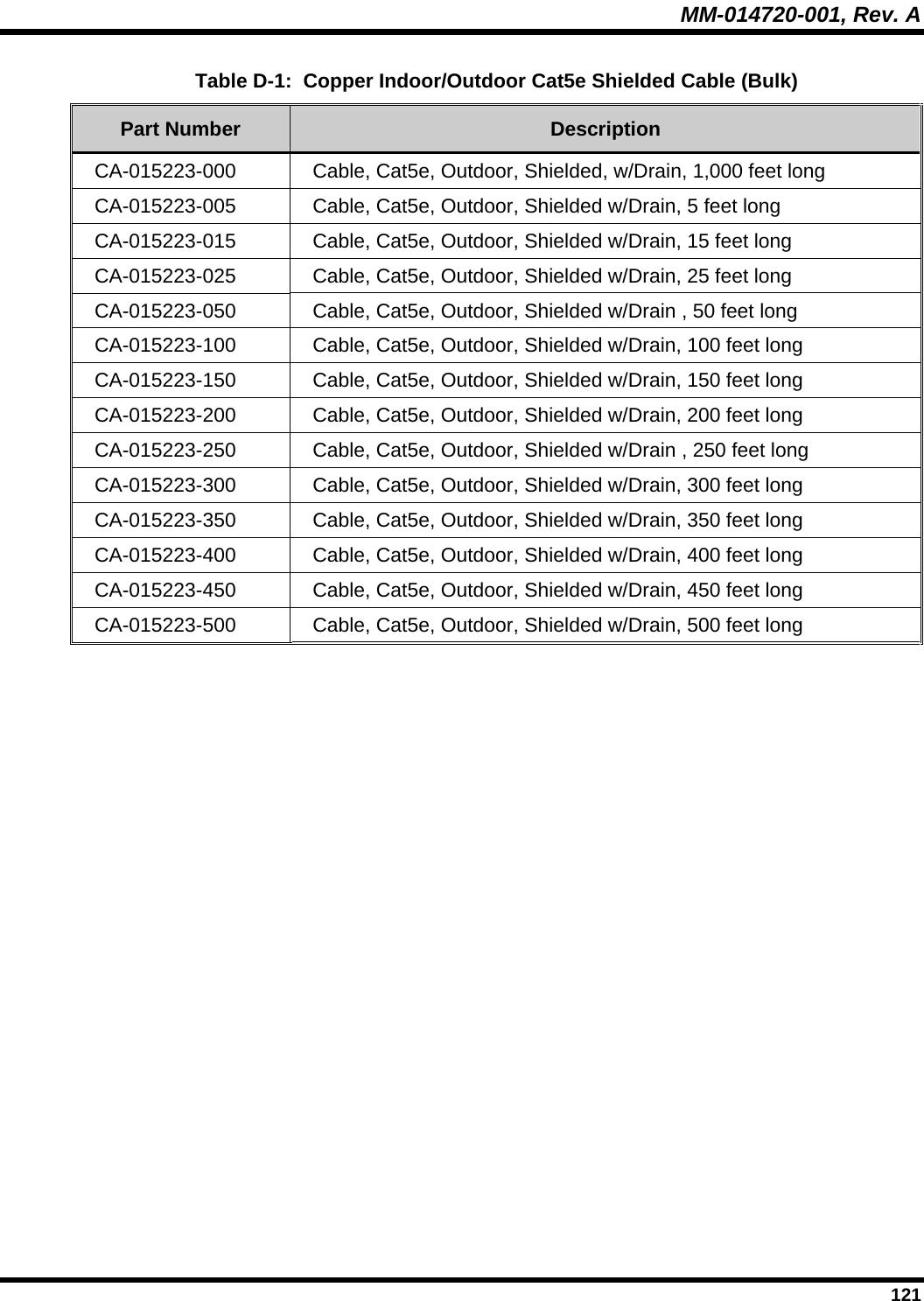
![MM-014720-001, Rev. A 126 CAUTION To avoid damage to the connection, the cable must be pulled GENTLY when seating the RJ-45 plug. 3. While holding the RJ-45 plug in position, rotate the cable fitting as shown in Figure D-7, Detail B until tightened to a torque of 1.7-2.8 N–m [15-25 lb–in.]. The given torque must be met in order for the cable fitting to seal the plug at the cable end. Figure D-7: Assembly Detail](https://usermanual.wiki/HARRIS/VIDA-BB-CL.Manual-2/User-Guide-1074976-Page-48.png)
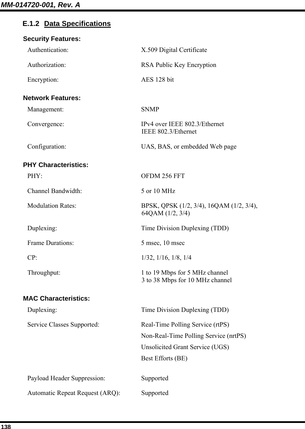
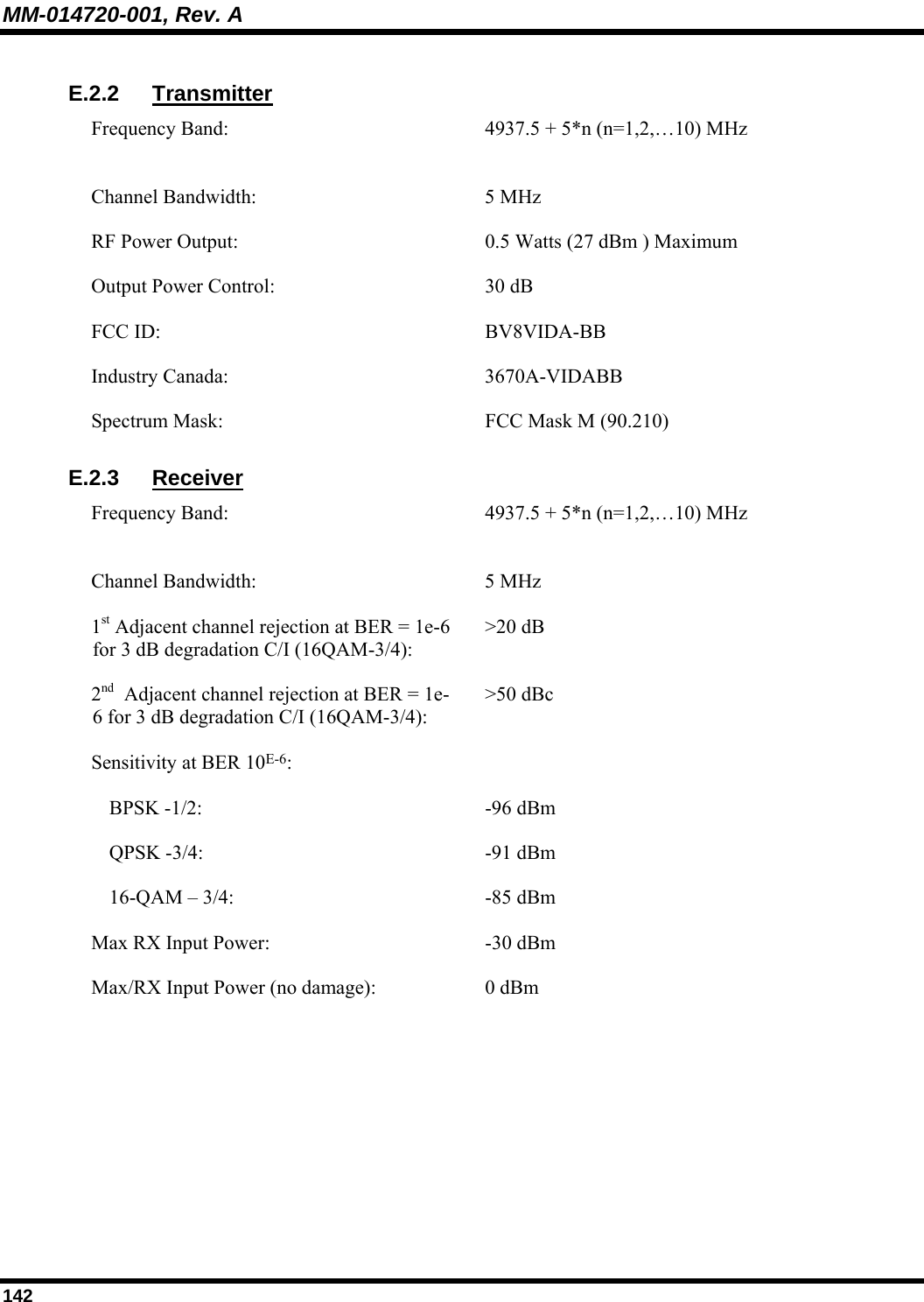
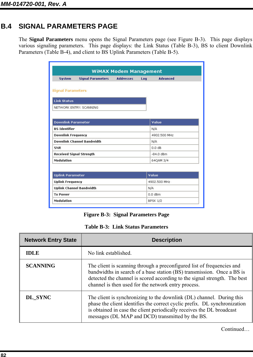
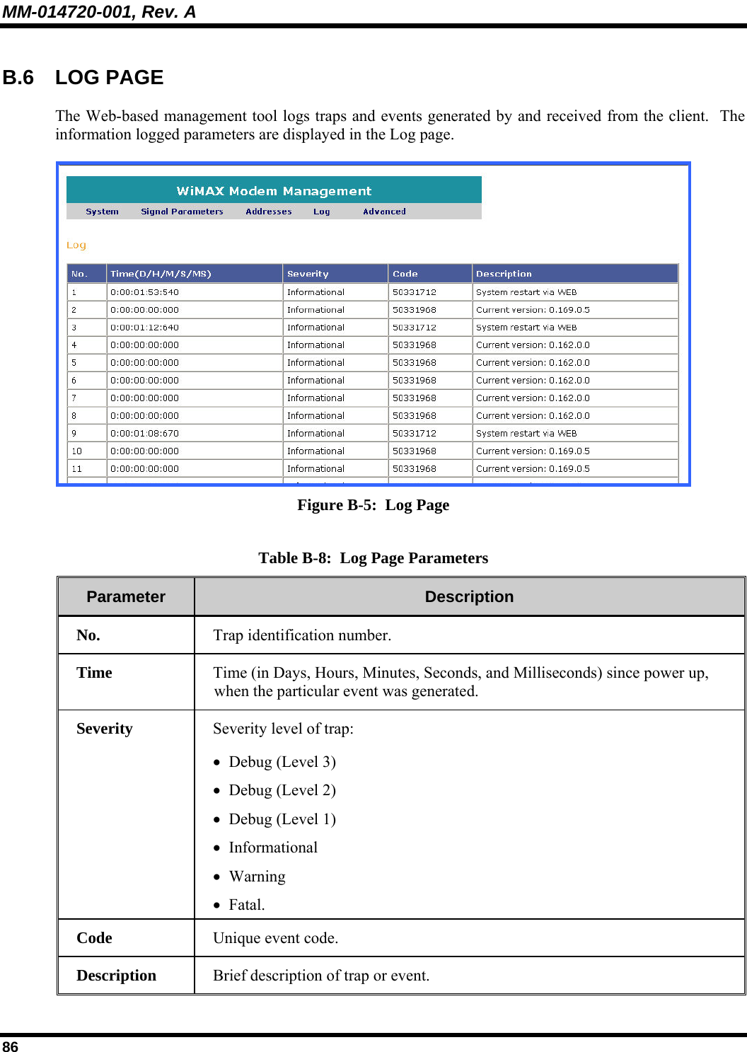
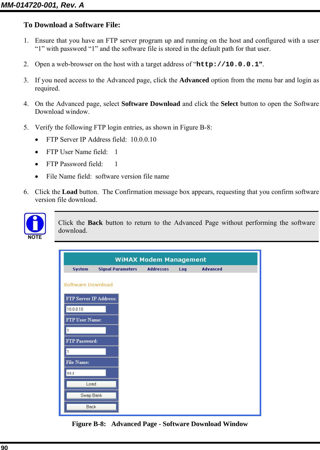
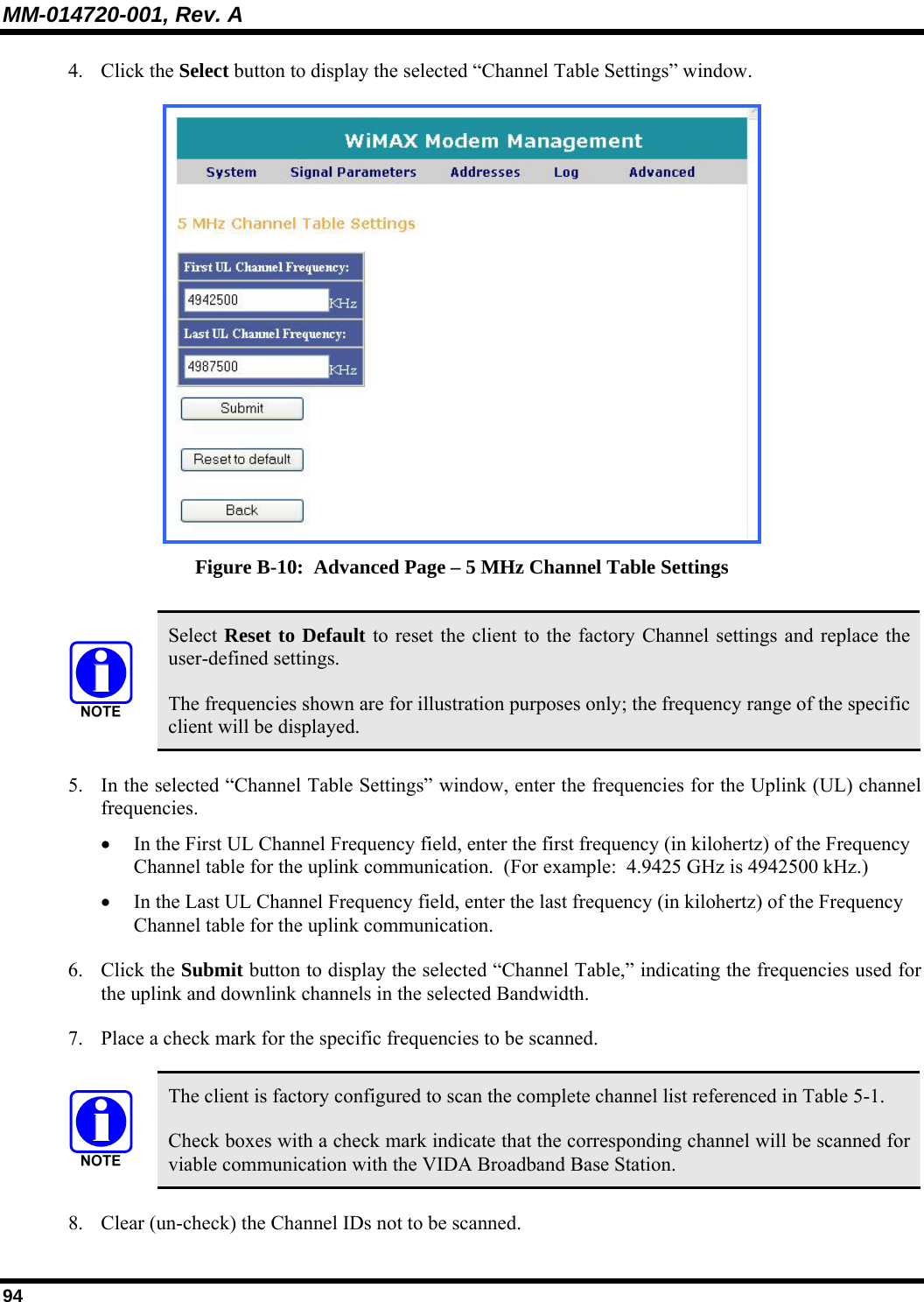
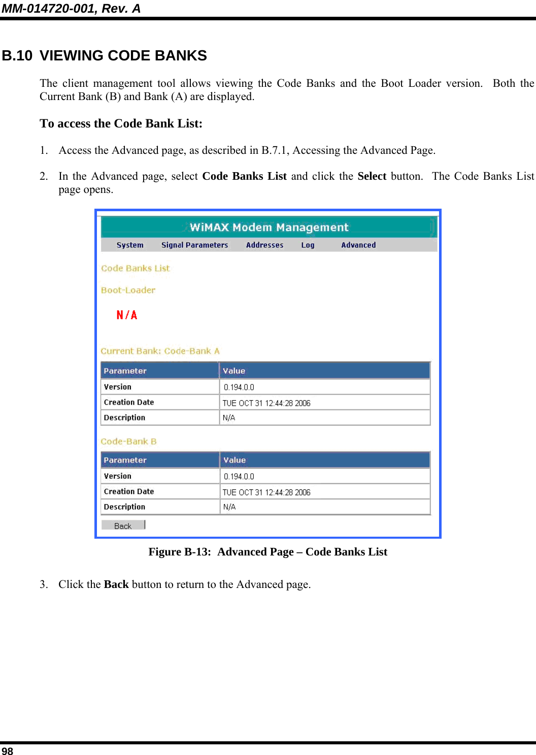
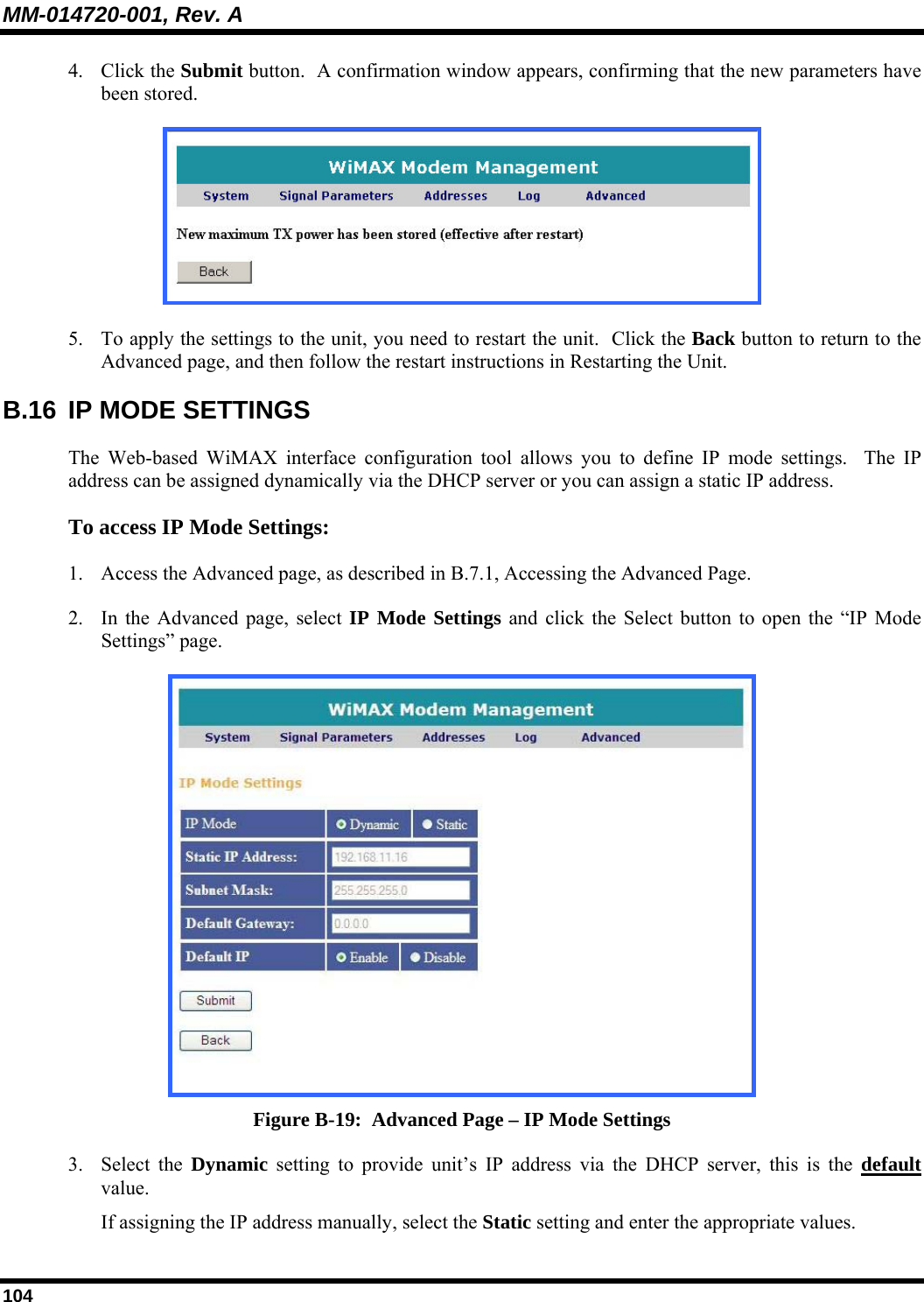
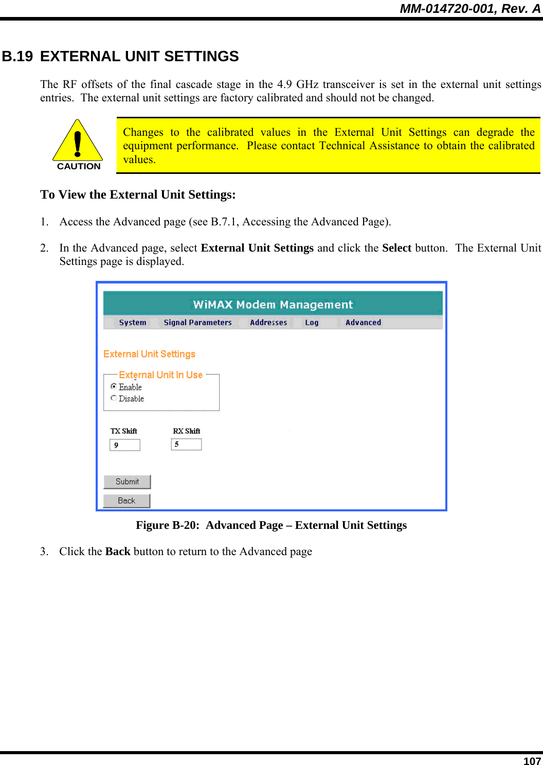
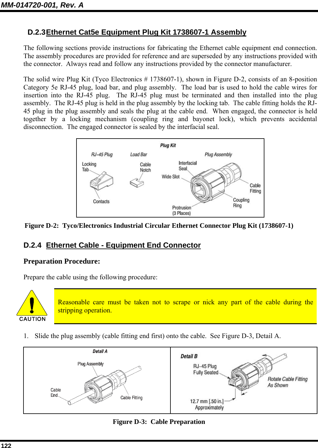
![MM-014720-001, Rev. A 127 D.2.5 Ethernet Cable - Shelter End Connector The following sections provide instructions for fabricating the Ethernet cable shelter end connector, Tyco Electronics part number 336462-1 (or equivalent). The assembly procedures are provided for reference and are superseded by any instructions provided with the connector. Always read and follow any instructions provided by the connector manufacturer. Figure D-8: Tyco Electronics 336462-1 Cat 5e (EMT) Plug Connector Assembly D.2.5.1 Cable Preparation Prepare the cable using the following procedure (refer to Figure D-9): CAUTION Reasonable care must be taken not to scrape or nick any part of the cable during the stripping operation. 1. Slide each boot over the relevant end of the cable before the cable stripping operation. 2. Strip the cable jacket 30 – 40mm [1.18 – 1.58 in.] as shown. 3. Fold the outside shield foil back over the jacket. 4. Foil must be trimmed up to 2.0mm [0.079 in.] max from the jacket end. Individual pair shields must be trimmed up to 2.0 [.079] max from the jacket end.](https://usermanual.wiki/HARRIS/VIDA-BB-CL.Manual-2/User-Guide-1074976-Page-49.png)