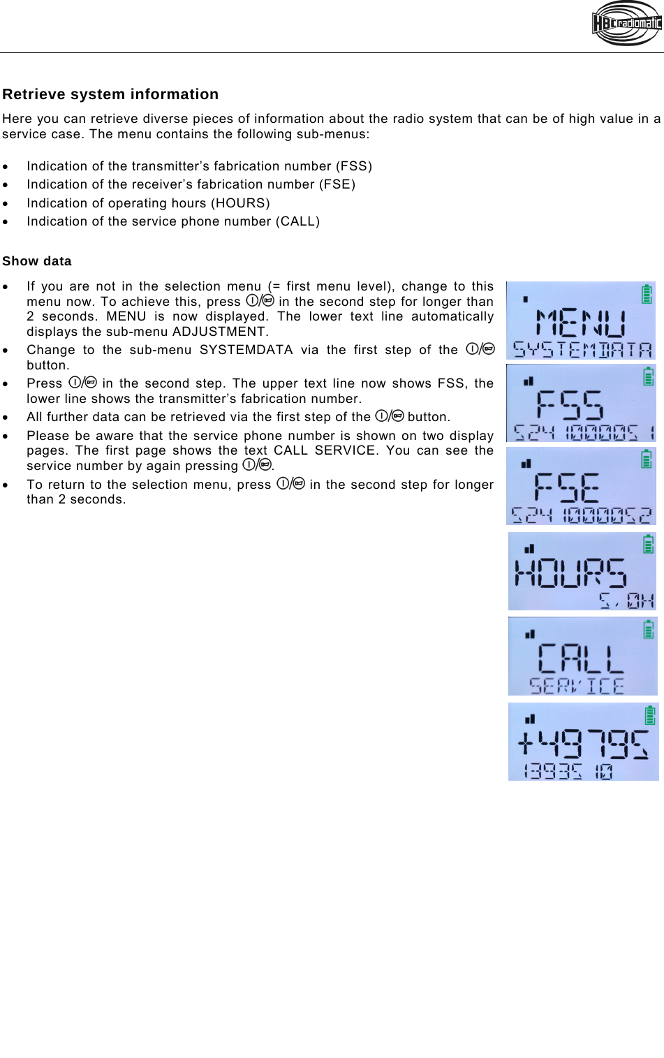
HBC radiomatic MICRON7 Remote control with RFID User Manual AOM70U00

HBC-radiomatic GmbH Remote control with RFID AOM70U00

User Manual

    micron 7 AOM70U00  Operating Instructions  Original Operating Instructions
   Table of Contents  Safety InstructionsIntended UseSafety Instructions for Installation and OperationFCC notesIC notesOperationActivating the TransmitterDeactivating the TransmitterAutomatic Switch-OFF (APO Function)DisplayStatus DisplayIndividual display settingsBattery and Battery ChargerCharging the batteryOptionsSafety FeaturesFrequency ManagementCatch-ReleaseTandem OperationCatch-Release-Tandem OperationCable Controlradiomatic® masterkeyAddress Changeover via Coding PlugUtilization of Button   as Shift KeyEnabling of the Proportional OutputsRotary Switch for Preselected SpeedSlewing Gear ReleaseFeedback by LEDRF-amplifierPre-selection of Trolley or HoistTransmitter Key upTechnical DataDimensionsTroubleshootingMaintenance  Attachments: Return delivery note, system specific views, circuit diagrams and /or output wiring  Pictographs  Danger due to electrical voltage. Touching live parts inside the unit can be fatal or cause serious injuries.   Instructions for occupational health and safety. Not following these instructions can cause accidents, which can cause damage, serious injuries or even death.   Important information about the operation of the radio system    Manufacturer:  HBC-radiomatic GmbH • Haller Straße 45 – 53 • 74564 Crailsheim • Germany • Tel. +49 7951 393-0 • info@radiomatic.com. HBC.radiomatic GmbH is not liable for any misprints or errors! – Specifications and design subject to change without notice.® radiomatic and radiobus are registered German trademarks. © 07 / 2011, HBC-radiomatic GmbH, 74564 Crailsheim, Germany No part of this document may be reproduced in any manner whatsoever without the expressed written permission of HBC-radiomatic GmbH.
   Safety Instructions Read through these operating instructions carefully before working with the radio system. This applies in particular to the installation, commissioning and maintenance of the radio system.  The operating instructions are a constituent part of the radio control system and must always be kept close at hand for the responsible personnel.  The term ‘machine’ is used in the operating instructions for the different possible uses of the radio system.   Intended Use   The radio system serves to control machines and for data transfer. Observe the job safety and accident prevention regulations applicable to each application.   The intended use also includes reading the operating instructions and adhering to all safety information contained therein.   The radio system must not be used in areas where there is a risk of explosion, nor for the control of machines used to convey persons, unless it is explicitly approved by the manufacturer for these uses.   Modifications to the radio system may only be carried out by specialist personnel who have been trained and authorized by HBC-radiomatic. All modifications must be documented at the factory in the radio control master file.    The radio control system safety devices must not be modified, removed or bypassed. In particular, modifications to any part of the radio system's complete emergency-stop system are impermissible.   Safety Instructions for Installation and Operation   The electrical connection per the accompanying output wiring diagram must be established by a qualified electrician exclusively.   The receiver may only be opened by trained personnel. Components inside the receiver can be energized at life-threatening voltages. The supply voltage for the machine must be deactivated before the receiver is opened.    Please also note with radio systems, that the presence of persons in the danger zone - in particular beneath the load (cranes!) - is prohibited in every instance.   Select a safe location for radio control, from which you have a good and complete view of the working movements of the machine, the load movements and the surrounding working conditions.   It is not permissible to put a radio transmitter unattended to one side whilst activated. Always switch the radio transmitter off when it is not required. This applies in particular if you change location, when working without radio control, during breaks and at the end of work. Always safeguard the radio transmitter against use by unauthorized persons, for example by locking it away.   In the event of an emergency and with all faults, switch the radio transmitter off immediately by pressing the STOP switch.   Only operate the radio system when it is in perfect working order. Faults and defects that could influence safety must be rectified before the system is put back into operation, by specialists who have been trained and authorized by HBC-radiomatic.    Note that the operational directions of the operating elements may appear inverted depending on location and viewing angle to the machine. This applies in particular to rotary cranes, if your location changes from inside to outside the radius of the crane.  The operator must make himself familiar with the directional markings on the machine before the start of work.    Repairs may only be carried out by specialist personnel who have been trained and authorized by HBC-radiomatic. Use original replacement parts and accessories (e.g. rechargeable batteries) exclusively; otherwise it is possible that the equipment safety can no longer be guaranteed and our extended warranty will be voided.    Remain vigilant when working with the radio system and familiarize yourself with its functions. This applies in particular if you are working with it for the first time or if you work with it only occasionally.    Check each time before starting work the function of the STOP switch. When you press the STOP switch with the transmitter on, the status LED and the display of the transmitter have to go out. If the status LED and the display don’t go out then you have to disable the radio control system immediately. Remove the battery and the radiomatic® iLOG from the transmitter and inform a service technician.
   FCC notes Part 15.21 Statement Changes or modifications made to this equipment not expressly approved by HBC-radiomatic GmbH may void the FCC authorization to operate this equipment.  Part 15.105 Statement This equipment has been tested and found to comply with the limits for a Class B digital device, pursuant to Part 15 of the FCC Rules. These limits are designed to provide reasonable protection against harmful interference in a residential installation. This equipment generates, uses and can radiate radio frequency energy and, if not installed and used in accordance with the instructions, may cause harmful interference will not occur in a particular installation. If this equipment does cause harmful interference to radio or television reception, which can be determined by turning the equipment off and on, the user is encouraged to try to correct the interference by one or more of the following measures:   Reorient or relocate the receiving antenna.   Increase the separation between the equipment and receiver.    Connect the equipment into an outlet on a circuit different from that to which the receiver is connected.    Consult the dealer or an experienced radio/TV technician for help.  RF Exposure Statement Radiofrequency radiation exposure information The radiated output power of the device is far below the FCC radio frequency exposure limits. Nevertheless, the device shall be used in such a manner that the potential for human contact during normal operation is minimized.    IC notes RSS-GEN – User Manual Statements  (English/French)  Licence exempt  This device complies with Part 15 of the FCC Rules and Industry Canada licence-exempt RSS standard(s). Operation is subject to the following two conditions: 1.  this device may not cause interference, and 2.  this device must accept any interference received, including interference that may cause undesired operation of the device.  Le présent appareil est conforme aux CNR d'Industrie Canada applicables aux appareils radio exempts de licence. L'exploitation est autorisée aux deux conditions suivantes: 1.  l'appareil ne doit pas produire de brouillage, et 2.  l'utilisateur de l'appareil doit accepter tout brouillage radioélectrique subi, même si le brouillage est susceptible d'en compromettre le fonctionnement.
   Operation  The transmitter is equipped with an electronic radiomatic® iLOG key. radiomatic® iLOG contains all the data required for operating the transmitter. Operation is not possible without radiomatic® iLOG! Depending on the version the radiomatic® iLOG can also be used for operation of replacement transmitters of identical construction.   When activating the transmitter and if the radio connection is interrupted (e. g. if the connection is lost or the transmission range is exceeded), the transmitter reacts with the so-called enforced zero-position.  Release all operating elements so they can return to the zero-position and actuate the Start-button. The machine will not react if the operating elements are not in zero-position. This prevents uncontrolled machine movements after the radio connection has been interrupted.              Activating the Transmitter  With standard start sequence Insert a charged battery into the battery compartment.   The following steps need to be carried out within 4 seconds: 1.  Pull the STOP switch. ENTER START-SEQ is now shown in the display.  2. Press the   button for a short time. The   symbol appears in the display. Release the button. The transmitter will switch off if the button is pressed for longer than half a second! 3. Press the   button again. The   symbol appears in the display. Keep the button pressed until the status LED flashes green. Then release the button.  4. The symbols       and two text lines appear in the display. The transmitter is now ready for operation.  Note:  The transmitter switches off when   the   button is pressed for longer than half a second in step 2 of the start sequence.   the start sequence is not completed within 4 seconds.    another button is pressed during the start sequence.    In such cases, press the STOP switch and repeat the entire start sequence!    Example  STOP switch Start button  Status LED  radiomatic® iLOG
   With HBC Smart Card 1.  Insert a charged battery into the battery compartment. 2.  Pull the STOP switch.  APPLY SMART CARD is now shown in the display. 3.  Hold your HBC Smart Card to the lower end of the transmitter (cf. illustration). 4.  The status LED flashes green. The following symbols are now shown in the display:      5.  The transmitter is now ready for operation. 6.  HELLO USER _ is shown in the display for 2 seconds.  Note:  The transmitter can only be activated with a valid Smart Card. If you use a card that does not match the respective transmitter or is not approved for this transmitter, CARD INVALID appears in the display. The transmitter is automatically shut down after 2 seconds. Please contact your superior in such cases.  The transmitter also shuts down if the start sequence is not completed within 10 seconds. In this case press the STOP switch and repeat the entire start sequence!    Caution: Before starting work always trigger the acoustic signal. This warns all colleagues that the machine is about to move.   Deactivating the Transmitter Press the STOP switch.  Note: Replace the battery when the battery display flashes red, an acoustic signal sounds, the status LED flashes red and the transmitter vibrates (option). Otherwise, the transmitter will switch off in a few minutes.  Recharge the empty battery in the respective charger.    Automatic Switch-OFF (APO Function) For safety reasons we have equipped the transmitter with an automatic switch-OFF (APO function).  The transmitter is automatically put out of circuit after approx. 15 minutes of non-use. The automatic switch-OFF also saves battery power.  After an automatic switch-OFF you must reactivate the transmitter as described in chapter “Operation”.  Caution: The automatic switch-OFF does not relieve the operator of his responsibility to turn off the transmitter with the STOP switch when not in use.
    Display  Status Display     Field strength (only for systems with feedback) The field strength indication provides information about the quality of the radio connection. With a perfect connection quality, all 5 bars of the indication are displayed green. The field strength indication is always visible when the transmitter is turned on.   Field strength is indicated in the following degrees:    Perfect reception signal      Weak reception signal  Symbol flashes: Feedback failure. The transmitter is not receiving signals from the receiver.   Note:  If the field strength is displayed in red or a feedback failure is displayed, the risk of losing radio connection is  imminent. In this case, ensure that the radio connection is not impaired by an obstacle (e.g. a building). Also take care that you are within the range of the radio system. It may be necessary to change the working position.     Battery The battery indication provides information about the current condition of the battery. It is always visible when the transmitter is turned on.  The battery status is displayed in the following degrees:     Battery charged.      Forewarning: The battery needs to be charged soon.   Warning: The battery has to be charged. About 30 minutes remain until the automated shut-down.   Field strength Battery
  Feedback  The feedback function is used to transmit various information and data from the machine or the radio  receiver to the radio transmitter. A number of symbols as well as two lines of text with 6 and 10 digits  respectively are available for displaying feedback information.    Feedback via symbols Symbol shines after the transmitter has been activated. The symbol disappears if there is a feedback or interface failure, an error notification or customer-specific warning message, or if the     symbol is displayed.   Symbol shines constantly or flashes. This symbol is defined by the customer.     Symbol flashes: Feedback failure. The transmitter is not receiving signals from the receiver.   Symbol flashes: There is an interface failure.   Symbol shines constantly or flashes: Warning! This symbol is defined by the customer.    Symbol shines constantly or flashes. This symbol is defined by the customer.     Note:  A detailed description of the displayed customer-specific feedback information has to be part of the operating manual of the specific machine in use. All instructions the operator has to follow in connection with the feedback information have to be written there as well.    Feedback via text lines The customer’s demand determines which feedback information is to be displayed. For example, line 1 can display the payload and line 2 simultaneously the crane capacity.  If only one line is needed for feedback information, the other line can be used for status information, for example the crane number.    Error notifications The display enables the indication of diverse error notifications that are directly connected to the radio system. If such an error occurs, the    symbol is displayed.   Simultaneously one of the following texts is displayed:  ERROR ERROR ERROR ERROR ADCON iLOG  KEYBOARD SI2COMMAND  In case of such an error notification immediately contact the responsible service technician! Beispiel
  Individual display settings The transmitter display enables the individual adjustment of the following basic settings:  Display brightness   Fixed text in line 1   Fixed text in line 2  Note:  Always perform individual settings while the battery is charged. An empty battery can lead to an automated shut-down during the setting process and to the loss of all entries up to this point.    Access The mentioned settings are only accessible in a special settings mode. To access this mode, the transmitter first has to be deactivated via the STOP switch. Afterwards there are 2 possible procedures, according to the transmitter version.   Standard version (= without HBC Smart Card) Perform the following steps in max. 4 seconds: 1.  Press the button on the right side of the   button in the second step and keep it actuated. 2.  Pull the STOP switch. 3. Press the   button momentarily and release it. If the   button is actuated for longer than half a second, the transmitter turns off! 4. Press the   button again until the status LED flashes green. 5.  MENU ADJUSTMENT is now shown in the display. Release the   button and the button on the right side. You are now in the first menu level.    Version with HBC Smart Card Perform the following steps in max. 4 seconds:  1.  Press the button on the right side of the   button in the second step and keep it actuated.  2.  Pull the STOP switch. APPLY SMART CARD is now shown in the display. 3.  Hold your HBC Smart Card to the lower end of the transmitter (cf. illustration). 4.  The status LED flashes green. MENU is shown in the first text line, ADJUSTMENT in the second text line. Release the button on the right side of the   button. You are now in the selection menu.
  Basic functions There are various menu levels available for entering individual settings. The level you are currently in is displayed in the first text line (= the upper line). In addition, bars appear in the left corner over the text line. The number of bars indicates the current menu level. By browsing with the navigation button, the second text line can display the respective available sub-menus or the configurable fields.          The display navigation and the input of your settings are made via the 2-step   button. This operating element has two basic functions:    The first step enables browsing between sub-menus or (in the last level of the menu structure) moving the cursor between the editable values and selecting the requested character. If the first step is pressed continuously, the display browses through the sub-menus until the   button is released or pressed into the second step. If you momentarily press the button once in step 1, the next sub-menu is selected.   The second step is used for menu selection and saving your settings.  All individual settings begin in the selection menu (the first text line here displays MENU). You can return to the selection menu from all levels easily. Simply press the   button in the second step for longer than 2 seconds.  In the selection menu there are 2 sub-menus, which are shown in the second text line:          Sub-menu ADJUSTMENT  Here you can adjust the display brightness and change the fixed texts in lines 1 and 2 of the display.   Sub-menu SYSTEMDATA Here you will find information about the radio system that can be useful in a service case (e.g. fabrication number, service phone number, frequencies etc.). Individual settings are not possible!    Note:  If you want to work with the transmitter after finishing your settings, you need to deactivate the transmitter via the STOP switch and reactivate it by the standard start-up sequence or your  HBC Smart Card. For safety reasons, changing directly from the settings mode to working mode is not possible.    Current menu Current menu level. Here: Level 1.  Selected sub-menu (further sub-menus or configurable fields can be displayed by browsing).
  Perform settings After successfully turning on the transmitter, MENU is shown in the upper line of the display. The sub-menu ADJUSTMENT is already selected in the lower text line. If the sub-menu SYSTEMDATA is shown, press   once in the first step until the requested sub-menu ADJUSTMENT is displayed.    Now press   in the second step. The sub-menu ADJUSTMENT is opened. ADJUST is displayed in the upper text line.  Here you can choose between 3 sub-menus, which are displayed in the lower text line: BRIGHTNESS Adjust display brightness FIX-TEXT 1  Change text line 1  FIX-TEXT 2  Change text line 2   In case the sub-menus FIX-TEXT 1 and FIX-TEST 2 are not displayed, these setting possibilities have not been ordered in your product version.    Set display brightness  Press   in the first step until the sub-menu BRIGHTNESS is displayed.   In order to open the sub-menu, press   in the second step.   BRIGHT is now displayed in text line 1. In line 2, an indication with some squares   flashes. The amount of squares indicates the display brightness (more squares mean a brighter display).  Press   in the first step until the desired brightness is set.   To save the desired brightness value, press   in the second step.   The brightness is saved and the display returns to the menu ADJUST BRIGHTNESS.   If you set an undesired brightness value by error, you can repeat this procedure at any time.
  Editing fixed text lines In the settings mode you can edit the 2 text lines of the display. Text changes have to be performed separately for each line respectively. Text line 1 contains 6 digits, line 2 contains 10. Each digit can display both letters and numbers.  How to change texts:   From the selection menu, change to the ADJUSTMENT menu (cf. chapter “Perform settings”).   Browse through the sub-menus BRIGHTNESS, FIX-TEXT 1 and FIX-TEXT 2. In case you wish to edit text line 1 in the display, select the sub-menu FIX-TEXT 1. If you wish to edit text line 2, select FIX-TEXT 2.   Open the desired sub-menu by pressing   in the second step.   The display now shows the selected text line TEXT 1 or TEXT 2, depending on which was selected. In the lower line you can see fields with text, numbers or placeholders . This is the content that has been displayed in the respective text line until now.   You can now edit each field individually (also fields with spaces) or enter text or numbers in each empty field. To achieve this, navigate the cursor with the first button step to the field you wish to change. The cursor’s position is indicated by a blue flash of the respective field.  Press   in the second step. The selected field flashes green and is ready for editing.    The selection of the desired letter / number is done by the first step of the  button. Press the first button step until the desired digit appears. To enter the digit, press   in the second step. The digit selection for this field is now completed. The next field flashes blue and again indicates the cursor’s position.    Repeat these steps with all fields you wish to edit.    If you wish to abort, press   in the second step for longer than  2 seconds. The display returns to the selection menu.   When you wish to save your entries, navigate the cursor with the first button step to the TEXT 1 (or TEXT 2) indication.  Press   in the second step. SAVE is now shown in the display.  To save, press   again in the second step. Your settings are now stored in the radio system. The display returns to the menu ADJUST BRIGHTNESS.   If you wish to work with the radio control after successfully saving, deactivate the transmitter via the STOP switch and reactivate the radio system with the respective start-up procedure.  Note: When saving, a bar graph indicates the advance of the saving process. Do not turn off the transmitter if the saving process is not completed.
  Retrieve system information Here you can retrieve diverse pieces of information about the radio system that can be of high value in a service case. The menu contains the following sub-menus:    Indication of the transmitter’s fabrication number (FSS)   Indication of the receiver’s fabrication number (FSE)   Indication of operating hours (HOURS)   Indication of the service phone number (CALL)  Show data   If you are not in the selection menu (= first menu level), change to this menu now. To achieve this, press   in the second step for longer than 2 seconds. MENU is now displayed. The lower text line automatically displays the sub-menu ADJUSTMENT.   Change to the sub-menu SYSTEMDATA via the first step of the   button.  Press   in the second step. The upper text line now shows FSS, the lower line shows the transmitter’s fabrication number.    All further data can be retrieved via the first step of the   button.   Please be aware that the service phone number is shown on two display pages. The first page shows the text CALL SERVICE. You can see the service number by again pressing  .   To return to the selection menu, press   in the second step for longer than 2 seconds.
   Battery and Battery Charger NiMH Battery The battery capacity (= the ability to store electric current) and the battery charge (= the actual amount of stored current) depend on the age of the battery and the environment temperature. Older batteries begin to lose capacity over time. If the temperatures are below 0 °C or above 40 °C, the charge decreases faster.   Note:   In all cases, charge the batteries completely before initial use and at intervals not exceeding  6 months if they are stored. This ensures that the batteries have their full capacity in use, even after long storage. Please refer to the date on the battery’s packaging.    Charge the battery fully before storing it for a prolonged period. Otherwise total discharge may occur.   Use only the associated HBC charger to charge the battery   Charge the battery at an ambient temperature of 0 – 40 °C (32 – 104 °F).    Charge the battery only when the battery display flashes red, an acoustic signal sounds, the status LED flashes red and the transmitter vibrates (option).     Always store rechargeable batteries at room temperature.     Protect the battery from short circuits and always store it in the protective cover provided.  When handled properly the battery can exceed 500 charging cycles    Battery Charger Depending on customer selection, an AC or DC charger is available.  Ensure that you observe the following instructions:   Use this charger only to charge the batteries specified on the type plate.    The charger may not be used in hazardous areas.   The charger has to be operated with the voltage indicated on the back.   The charger has to be used in vehicles or indoors only.   Use the charger only within the specified temperature range.   Protect the charger against heat, dust and humidity.    Do not cover the charger while it is in use.    Disconnect the charger from the power supply when it is not in use.    In case of any fault of the charger or the connecting cable disconnect it immediately and put it out of operation.    Do not make technical changes to the charger or the connecting cable.    Defects must be repaired by qualified personnel only.    Three LEDs indicate the actual operating state of the battery. LED green: Illuminates when battery is charged.  LED orange: Illuminates when battery is charging. LED red: Illuminates when battery is deep discharged or defective.     Note: If a deep discharged battery is inserted into the charger, the red LED will illuminate for a few seconds before charging is started (LED orange illuminates).
   QA108600 / QD108300 / QD308300 with EC type-approval The charger is supplied with a connecting cable with a matching power plug.    Charging the battery 1.Connect the charger via the connecting cable to the power supply. 2.Insert the battery into the compartment.   Charging will start automatically.   Technical Data Operating voltage  100 – 240 V AC (QA108600) 10 – 30 V DC (QD108300 / QD308300) Charging time  ca. 3 h Operating temperature  10 – 40 °C (50 – 104 °F) Housing material  Plastic Protection class  II
   Options The availability of the following functions depends on the design and configuration of your radio control system.    Safety Features  radiomatic® shock-off / roll-detect / zero-g / inclination switch The safety features enable a quick shut-down of the radio control in specific emergency situations. Therefore, these intelligent functions prevent a dangerous unintended command from being given to the crane or machine.  radiomatic® shock-off can trigger a quick automatic shut-down of the radio control in case of an impact to the transmitter – e. g. if the transmitter is being hit by a massive object thereby getting out of control.   radiomatic® roll-detect can automatically detect rolling of the transmitter and, in this case, initiate a quick shut-down of the radio control.   radiomatic® zero-g can automatically detect if the transmitter is dropped or being thrown to another user. In such cases, zero-g can trigger a quick automatic shut-down of the transmitter.   inclination switch can deactivate the transmitter, if it exceeds an inclination angle of approx. 130° – 170° for a certain time and/or if it is placed front side down.    When the transmitter was shut down with radiomatic® shock-off/roll-detect/zero-g or inclination switch, the start button has to be activated until the status LED flashes green. Then the transmitter is ready to operate again.   The safety features do not relieve the operator of his responsibility to turn off the transmitter with the STOP switch when not in use.
   radiomatic® infrakey The radio system can only be activated via an infrared link between the transmitter and the receiver. This increases the safety of operation, i.e. the machine can not become inadvertently enabled.   radiomatic® infrakey operates either with an infrared module in the receiver housing (radiomatic® infrakey internal) or with the offset infrared antenna focus I (radiomatic® infrakey external).  To activate radiomatic® infrakey, actuate the start button on the transmitter.        Function of radiomatic® infrakey with focus I   Notes:   The range of the infrared beam is max. 20 m (66 ft).   The angle of radiation is 30°.   The front panel of the receiver must be visible (only radiomatic® infrakey internal).    Joystick with Deadman Function In order that it is possible to issue control commands the button integrated into the joystick must be pressed before the joystick is moved. The function then reverts to self-locking and remains effective until the joystick is back in the zero position. This enables the avoidance of potential risks through the unintentional actuation of the joystick.    Vibration Alarm With the vibration alarm, the operator can be informed of an impending need to change the battery and/or potential dangers on the machine through the vibration of the transmitter. This information can be for example pre-warnings for high wind speeds or threatening excess crane loads.    Front Panel Lighting With the front panel lighting potential dangers resulting from incorrect operation, based on poor visibility, can be prevented. The operator simply switches on multiple LEDs, which are integrated into the rollover bar, with a switch or button on the transmitter.
   Shut-off on Implausible Control Commands The automatic shut-off will activate after a sequence of multiple questionable movement commands. If, for example, one or more joysticks on the transmitter are actuated successively in different directions in an irregular manner, the system switches off automatically. This function protects the operator and the whole work environment from potential dangers as well as the machine from wear resulting from rapid and erratic movements.  After an automatic switch-off you must reactivate the transmitter as described in chapter Operation.    Micro Drive With the micro drive function the speed of the machine is limited to a preselected level. Even at full movement of the joystick/linear lever, the operator can not exceed this speed limit. In this manner demanding drive maneuvers can be managed and inexperienced users can be protected from potential dangers that can result from “speeding”.     Orthogonal Drive (Electronic Cross Gate) With the orthogonal drive function dangerous situations, caused by unintentional diagonal movements are being prevented. The operator will have to return the joystick back to zero position before another directional command can be activated. This function is suitable for example for situations where the operator has to make precision commands in confined areas. Diagonal movements are not possible.    User identification The "user identification" function with the HBC Smart Card enables a simple personalization of the radio system as well as the storage of all user profiles in the radio system. Safety relevant functions can be released to authorized personnel only and unauthorized users can be protected of potentially dangerous situations. In addition the radio system can store user-related all operating processes as well as the respective on time of the radio system. This data can be read from the radio system and shows how long the radio system was in use and how the individual operators used the various functions of the radio system.
   Frequency Management  Fixed Frequency  If the identification plate in the battery compartment of the transmitter shows a frequency value (e.g. 433,500 MHz), the transmitter operates with a fixed frequency. Please contact you service department if the frequency has to be changed because the radio channel is already assigned to another user.   Frequency Selection via Scanner  Transmitter and receiver are equipped with four frequencies (refer to wiring diagrams). If the radio channel is occupied, you can switch to another radio channel by using the rotary switch on the transmitter. The scanner in the receiver automatically resets the transmitter to the new frequency selected within one second.    Manual Frequency Switching  If the identification plate in the battery compartment of the transmitter shows the label man, the transmitter features manual frequency switching. This function can be used to change the radio channel during radio operation. Actuate the start button into the first step until an acoustic signal sounds. Then release the button.  Please contact your service department if all available frequencies are occupied.   radiomatic® AFS  If the identification plate in the battery compartment of the transmitter shows the label AFS, the transmitter is equipped with radiomatic® AFS (Automatic Frequency Selection). When activating the transmitter radiomatic® AFS will check if the present radio channel is free. If the radio channel is occupied, the system automatically finds and saves a free radio channel.  If the radio channel currently in use is occupied by another radio control system, you must switch the transmitter off and on again in order to allow radiomatic® AFS to switch to a free radio channel. The radiomatic® AFS option also includes the manual frequency switching function.  Note: If radiomatic® AFS is to perform optimally, all the other radio systems in the immediate working environment (e.g. the factory hall or building site) should be switched on before starting to use the radio system for the first time. This allows radiomatic® AFS to detect automatically which radio channels are already being used in the working area, and thereby to choose a suitable free channel for its own use.  In addition, when switching the radio system on for the first time, the user should make sure that his distance from the radio receiver and from the machine is a realistic reflection of the working situation.   radiomatic® AFM If the identification plate in the battery compartment of the transmitter shows the label AFM the transmitter is equipped with radiomatic® AFM (Automatic Frequency Management). radiomatic® AFM detects available radio channels constantly. If the radio channel currently in use is occupied by another radio control system, radiomatic® AFM switches automatically to a free radio channel.
   Catch-Release Via the Catch-Release option two or more transmitters can control a machine alternately. When the receiver is switched on, the machine can initially be controlled via any associated transmitter. Once the receiver was taken over by one transmitter, the other transmitters no longer have access.   Take over machine 1.Switch the transmitter on. 2.Enter the  "Catch" command on the transmitter and actuate the start button.  The access rights for the machine remain with that transmitter until the "Release" command is issued by that transmitter.   Release machine 1.Enter the  "Release" command on the transmitter. 2.Switch the transmitter off. The access rights for the machine are cancelled. Machine control can be taken over by another transmitter.   Operating Example: Transmitter 1 has taken over the machine. Transmitter 2 is to be given control.  1.Enter the "Release" command on transmitter 1. 2.Switch transmitter 1 off.  3.Switch transmitter 2 on.  4.Enter the "Catch" command on transmitter 2 and actuate the start button.  Transmitter 2 now has sole access to all machine functions.   Notes:    If a receiver has already been adopted by a transmitter can be displayed via a lamp on the machine.   If the operating voltage of the receiver fails, the receiver returns to the starting condition in which it can be adopted by any transmitter. If necessary, the receiver must be adopted anew.   If the transmitter is deactivated without the command "Release" having been issued, the other transmitters have no access to the receiver. The starting condition described above can only be resumed by deactivating the operating voltage at the receiver.
   Tandem Operation Tandem Operation T1 The radio system consists of 1 transmitter and 2 receivers for 2 machines. The transmitter can control the machines individually or in parallel  The machines are selected at the transmitter via a rotary switch: A only machine A A+B  machine A + machine B B   only machine B    Tandem Operation T2 The radio system consists of 2 transmitters and 2 receivers for 2 machines. Both transmitters are master transmitters and can control the machines individually or in parallel. During normal operation transmitter 1 controls machine A and transmitter 2 controls machine B. In order to be able to switch to machine B or A+B at transmitter 1, for example, the key must be removed from transmitter 2 and inserted in transmitter 1.  The machines are selected at the transmitter via a rotary switch: A  only machine A A+B  machine A + machine B B   only machine B  Operating Example: Control of machine A + B via transmitter 1. 1.Switch transmitter 1 and 2 off and remove the key from transmitter 2. 2.Insert the key from transmitter 2 in transmitter 1.  Machine selection via transmitter 1 is activated.  3.Turn the rotary switch of transmitter 1 to A+B.  4.Switch transmitter 1 on and actuate the start button.  The radio system now operates in tandem mode.   Warning: For safety reasons, it is imperatively required that only one key is available for each transmitter. The spare key must be stored at a superior, authoritative position and only be handed out in clarified cases.
  Tandem Operation TM/TS The radio system consists of 2 transmitters and 2 receivers for 2 machines. One transmitter is a master transmitter and can control the machines individually or in parallel. The other transmitter is a slave transmitter and can only control machine B.  In order to be able to switch to machine B or A+B at the master transmitter, the key must be removed from the slave transmitter and inserted in the master transmitter.   The machines are selected at the transmitter via a rotary switch: A  only machine A A+B  machine A + machine B B   only machine B  Operating Example: Control of machine A + B via master transmitter. 1.Switch master and slave transmitter off and remove the key from slave transmitter. 2.Insert the key from slave transmitter in master transmitter. Machine selection via master transmitter is activated. 3.Turn the rotary switch of master transmitter to A+B. 4.Switch master transmitter on and actuate the start button.  The radio system now operates in tandem mode.  Warning: For safety reasons, it is imperatively required that only one key is available for each transmitter. The spare key must be stored at a superior, authoritative position and only be handed out in clarified cases.
   Catch-Release-Tandem Operation With the Catch-Release-Tandem Operation two or more transmitters can control several machines alternately. Each machine is equipped with a receiver that can receiver and monitor all transmitter frequencies.  After activating the receivers all transmitters have equal access to the radio control system.  Take over machine 1.Switch the transmitter on. 2.Turn rotary switch on the transmitter to the respective position.  3.Enter the "Catch" command on the transmitter and actuate the start button. The transmitter with control over the machine(s) retains the access to the receiver until the operator has issued the "Release" command.   Release machine 1.Enter the "Release" command on the transmitter. 2.Switch the transmitter off. The access rights for the machine(s) are cancelled. Machine control can be taken over by another transmitter.   Operating Example: Transmitter 1 has taken over machine A. Transmitter 2 is to be given control over machine A+B.  1.Enter the "Release" command on transmitter 1. 2.Switch transmitter 1 off.  3.Switch transmitter 2 on.  4.Turn rotary switch on transmitter 2 to A+B. 5.Enter the "Catch" command on transmitter 2 and actuate the start button.  Transmitter 2 now has sole access to all machine functions.    Notes:    If a receiver has already been adopted by a transmitter can be displayed via a lamp on the machine.   If the operating voltage of the receiver fails, the receiver returns to the starting condition in which it can be adopted by any transmitter. If necessary, the receiver must be adopted anew.   If the transmitter is deactivated without the command "Release" having been issued, the other transmitters have no access to the receiver. The starting condition described above can only be resumed by deactivating the operating voltage at the receiver.
   Cable Control With a cable you can generate a direct data connection between the transmitter and receiver. The radio transmission is disabled. At the same time, the power supply of the transmitter is provided through the cable, as well.  Connecting the cable 1.Switch the transmitter off. 2.Remove the screw lock on the transmitter and receiver.  3.Connect the transmitter and the receiver with the cable. Ensure that the connector is locked.  4.Switch the transmitter on.     Notes:   If you connect the cable while working with the system, the transmitter will switch off automatically. Actuate the start button to switch to cable operation.    When the system is in cable mode the transmitter will receive the supply voltage from the receiver, i.e. the transmitter can be used without the battery.    If you disconnect the cable from the transmitter and receiver, the system will switch off automatically. Actuate the start button to switch back to radio operation.    radiomatic® masterkey This option offers the possibility for the operator to easily exchange a defective transmitter for a spare transmitter. radiomatic® masterkey (key) holds all the pertaining system information such as frequency and address code. When the radiomatic® masterkey is inserted into the spare transmitter all necessary information is transmitted. Data transfer only works with transmitters that are equipped with this option. Otherwise the radiomatic® masterkey is only used for switching the transmitter on or off. If a transmitter without radiomatic® masterkey preparation is operated with a radiomatic® masterkey (mechanically the key has the same function), it will therefore continue to function with "its" internally programmed receiver (see type plate).
   Address Changeover via Coding Plug The coding plug activates a preselected frequency and address coding in the transmitter which corresponds with the data of the respective receiver. If the coding plug is inserted in a spare transmitter, it will receive the same data as the original transmitter. The spare transmitter can therefore now access the receiver   Changing the coding plug:   Turn the union nut to the left and pull out the coding plug.    Put the coding plug into the socket of the spare transmitter and lock it by turning the union nut to the right.   Notes:    Operation is not possible without coding plug.    If the coding plug is removed during operation the transmitter switches off immediately.    The coding plug is labeled with the fabrication number of the respective receiver.     Utilization of Button   as Shift Key The RPM+ and RPM– buttons have a dual function. If the button   is kept depressed and the RPM+ resp. RPM– button is also activated, the Motor Start resp. Motor Stop command will be output.    Enabling of the Proportional Outputs The start button must be depressed after the system has been activated and enabled via Si1 (at the receiver). It is not until this has been done that the function of the compact linear levers at the receiver will be enabled.    Rotary Switch for Preselected Speed Using the rotary switch it is possible to choose between four maximum machine speeds, which are set in accordance with the customer’s requirements.   The symbols for the speed adaptation have the following meanings:    = maximum speed 100 %    = maximum speed, limited to 75 %     = maximum speed, limited to 50 %    = maximum speed, limited to 25 %
   Slewing Gear Release Note: Whenever the command "slewing gear release" is actuated by means of the radio control, it is important that the respective check be made. Due to the above, a clearly visible indicator lamp should be installed on the machine.    Feedback by LED Using this function, system or machine data can be displayed on the transmitter by LEDs.    RF-amplifier If the transmitter is equipped with an RF-amplifier, please refer to the transmitter wiring diagram. There you can also find the directions on how to activate the RF-amplifier.    Pre-selection of Trolley or Hoist The operator is able to select the trolley or hoist that he wishes to control. It is also possible to simultaneously control both trolleys/hoists, for example in order to transport particularly long or wide loads.    Transmitter Key up With the transmitter key up function, radio commands are only transmitted at the touch of a key and the transmitter will automatically be switched off after 7 seconds of non-use. For example, self-monitoring gates can thus be opened or closed by several operators. During longer breaks the transmitter must be switched off by pressing the STOP switch. The "transmitter key up" function also saves battery power.  Caution:  The transmitter key up function does not relieve the operator of his responsibility to turn off the transmitter with the STOP switch when not in use.
   Technical Data  Unique system addresses   over 1.000.000 combinations Supply voltage  3,6 V EMS category  The mains supply is cut off by a STOP switch. Therefore, the criteria for an elimination of errors according to EN ISO 13849-2 chapter D.5.3., table D.8 (non-opening of contacts) are met. The performance level of the respective receiver applies. Frequency ranges  308 – 338 MHz, 405 – 475 MHz1, 865 – 870 MHz,  902 – 928 MHz; 1210 – 1258 MHz1 DECT: 1880 – 1900 MHz 1 Not all frequency ranges available.  Channel spacing  12,5 / 20 / 25 / 50 / 250 kHz DECT: 1,728 MHz Transmitter antenna  internal Battery type  BA223030 (NiMH) Battery capacity  2100 mAh Continuous operating time  ca. 17 h (standard version without feedback) Operating temperature range  −20 °C – 70 °C hazardous areas zone 2: −20 °C – 60 °C (−4 °F – 140°F) Housing material  impact-resistant plastic Dimensions  240 x 68 x 58 mm (9.5 x 2.7 x 2.3 ") Weight (incl. battery)  ca. 550 g (1.2 lb.) Protection class  IP 65
   Dimensions
   Troubleshooting Note: Please check the functions using the cabin or cable controls first!  Problem Possible Cause  Remedy Transmitter does not react when switched on.  No power.    Check battery contacts for damage or contamination.   Insert a fully charged battery into the battery compartment.  Recharge battery. Low-power indication after minimal operating time.   Battery contacts are contaminated or damaged.  Battery not charged.  Battery defective.   Check battery contacts for damage or contamination.  Recharge battery.  Ensure that recharging process runs correctly.  Check transmitter functions using a fully charged or replacement battery. The display in the transmitter flashes green but it is not possible to effect control commands.   Receiver has no voltage.  No radio communication.   "Crane On" command has not been given.   Check the connecting cable to the receiver.   Check the functions via the LEDs in the radio status panel of the receiver. Some commands are not carried out.   Receiver defective.   Interruption in the connecting cable to the machine.    Check if all connecting cables and cable junctions are tight.    If none of the measures mentioned resolve the problem, then please contact your service technician, dealer or HBC-radiomatic, Inc.
   Maintenance The radio control system is virtually maintenance-free. Please observe the following points:    Check the STOP switch functionality at regular intervals. Dirt deposits on the switch can hinder the mechanism and impair the function.   Check the rubber bellows or rubber seals of the operating elements at regular intervals for leak-tightness. Replace immediately if cracks appear since the penetration of dirt and humidity may damage the function of the operating elements.   Never use a high-pressure cleaner or sharp or pointed objects to clean the transmitter.   Charge and discharge transmitter batteries regularly.   In the Event of a Fault Warning: Never operate a machine with a faulty or defective radio control system!    Never try to repair the electronics of the radio control system! Opening the transmitter or receiver housing terminates the manufacturer guarantee.   Send any defective or faulty equipment to your local distributor or to HBC-radiomatic, Inc. They are experts and have the necessary know-how and OEM spare parts.   Always send both transmitter and receiver and enclose a detailed description of the problem.    Do not forget to enclose your address and telephone number so that we can get in touch with you quickly if necessary.   To avoid damage during transport, use the original packing supplied with the transmitter and receiver, otherwise pack securely. Send the consignment to your distributor or to the following address: HBC-radiomatic, Inc. 1017 Petersburg Road Hebron, KY 41048, USA Telephone: +1 800 410-4562 Fax: +1 866 266-7227   Should you decide to personally return a defective radio system to your distributor or  HBC-radiomatic, Inc., then please make an appointment first.
 Form  Return Delivery Note      Date: 27.07.2004 U. Weissmann / G. Brose / A. Hemming    Revision: 10 Page: 1 of 1   HBC  HBC-radiomatic GmbH    Phone:  + 49 (0)7951 393 800 Haller Str. 45 – 53  Transaction No. (provided by HBC):  Fax:  + 49 (0)7951 393 802     Email: service@radiomatic.com 74564 Crailsheim, Germany ...................................................................... Internet:  www.hbc-radiomatic.com   Contact for further information:  Contact person:  ..........................................……..  Phone:  ........................................  Fax: ……………………………….  .............................................................................. Email: ………………………………   Reason for goods return *):   Repair      Estimate required?   yes       no   Modification     Wrong order    customer’s order no.: ..……………………………………………………. Wrong delivery     For credit        corresponding invoice no.: ……............................................... ….…. *) in order to work on your return rapidly, please state precisely the fault report and invoice no.   HBC Fabr. No.: .................................   Description of problem:  Transmitter: ......................................   ...................................................................................................................  Receiver: ..........................................   ...................................................................................................................  Charger: ...........................................   ...................................................................................................................  Batteries: ..........................................   ...................................................................................................................  Cable: ...............................................   ...................................................................................................................  Other accessories:  ...........................   ...................................................................................................................                             Absolutely necessary information::  PCB...............................  from system  Problem appears:  due to vibration / shock     if warm or hot        Fabr. No.:  .........................................   if cold        ......................................   sometimes     commonness: ……………….. ......................................   always     ......................................   never     (in good order, not needed pcb)      Note:  For system repairs, please send (if possible) the complete system including transmitter, receiver, batteries, charger and cable with detailed description of the problem.  The return is subject to the conditions described in paragraph 8 (Guarantee) in our standard terms & conditions.  Returns will only be accepted CIF Crailsheim, Germany. Preferred shipping via DPD and UPS Standard. Please use the original HBC packaging if possible. Please use proper packaging to avoid electrostatic discharge hazards with pcbs and/or modules. Warranty claims may not be accepted in case of improper packaging. Returns shipped ex works or unpaid will not be accepted without express written consent by HBC.
Weitergabe sowie Vervielfältigung dieser Unterlage, Verwertung und Mitteilung ihres In-halts sind nicht gestattet, soweit nicht ausdrücklich zugestanden. Zuwiderhandlungenverpflichten zu Schadensersatz. Alle Rechte für den Fall der Patentierung oder GM-Ein-tragung vorbehalten.Copying of this document, and giving it to others and the use or communication of thecontents thereof, are forbidden without express authority. Offenders are liable to thepayment of damages. All rights are reserved in the event of the grant of patent or theregistration of a utility model or design.HBC-radiomaticGMBHFormblatt RücklieferscheinErstellt am: 27.07.2004Von: U. Weissmann / G. Brose / A. HemmingRevision: 9Seite: 1 von 1HBCHBC-radiomatic GmbH Tel.: + 49 (0)7951 393 800Haller Str. 45 – 53 Vorgangs-Nr. (von HBC vergeben) Fax: + 49 (0)7951 393 802E-Mail: service@radiomatic.com74564 Crailsheim …………………………………………………. Internet: www.hbc-radiomatic.comKontakt bei RückfragenAnsprechpartner:  ..................................... …….. Telefon:  ....................................  Fax: ………………………………........................................................................... Email: ………………………………Grund der Rücklieferung *):Reparatur  Kostenvoranschlag gewünscht? ja      neinUmbauFalschbestellung  zu Bestell-Nr.: …………………………………………………………….Falschlieferungzur Gutschrift  zu Rechnungs-Nr.: .......................................................................*) Um Ihre Rücklieferung rasch bearbeiten zu können, geben Sie bitte die Fehlerbeschreibung sowie die Rechnungs-Nr. der Ware an.HBC Fabr. Nr.:  ............................... Fehlerbeschreibung:Sender: .......................................... .............................................................................................................Empfänger: .................................... .............................................................................................................Ladegerät: ...................................... .............................................................................................................Akkus: ............................................ .............................................................................................................Anschlusskabel: ............................. .............................................................................................................Sonstiges Zubehör:  ........................ .............................................................................................................unbedingt auszufüllen::Platine........................... aus System Mangel tritt auf: bei Erschütterungbei Wärmemit Fabr. Nr.: .................................. bei Kältemanchmal  Häufigkeit: ..............................immernie  (intakte, nicht benötigte Platine)Hinweis:Bitte senden Sie bei System-Reparaturen möglichst das komplette System zurück - inkl. Sender, Empfänger, Akkus, Ladege-rät und eventuell Anschlusskabel mit einer detaillierten Fehlerbeschreibung.Die Rücksendung erfolgt unter Beachtung der in Ziffer 8 (Gewährleistung) unserer Allgemeinen Geschäftsbedingungen enthal-tenen Bestimmungen.Bitte liefern Sie die Ware frei Haus an uns zurück! Bevorzugte Speditionen: DPD und UPS Standard. Verwenden Sie mög-lichst die original HBC Umverpackung für die Rücklieferung. Für elektronische Bauteile und/oder Platinen ist eine ESD-Schutz-Verpackung zu verwenden. Garantieansprüche können bei Fehlen der ESD-Schutz-Verpackung erlöschen.Anlieferungen „unfrei“ ohne vorherige schriftliche Freigabe durch HBC werden nicht akzeptiert.

Navigation menu