HBC radiomatic PMNTU4 Wireless Crane Control User Manual BE PM NTU US L
HBC-radiomatic GmbH Wireless Crane Control BE PM NTU US L
Users Manual
Operating Instructions
Radio Transmitter PM NTU
BE-PM_NTU-US-L.DOC [ Word 97 ] FL Page 1 / 16
HBC-radiomatic, Inc. , Cincinnati , Ohio 45242 , USA
Information and specifications subject to change without notice. 2000-08-16
Radio Control System
HBC – Radio Controls
RRaaddiioo TTrraannssmmiitttteerr PPMM NNTTUU
for Industrial Cranes
made for
HBC-electronic
Funktechnik GmbH
Tel.: +49(0)7951/393-0
Made in Germany
Prod.Code: SNTU 1.0
Transmitter Ser.No.: 735-
IP55 / Nema 4 U: 6V DC
Frequency Band (MHz): 902 918
W5 : FB1
FCC-ID: NO9 SNTU04
Batt.
–
CANUSA

Operating Instructions
Radio Transmitter PM NTU
Page 2 / 16 BE-PM_NTU-US-L.DOC [ Word 97 ] FL
HBC-radiomatic, Inc. , Cincinnati , Ohio 45242 , USA
2000-08-16 Information and specifications subject to change without notice.
Radio Control System
Manufactured by : HBC-radiomatic GmbH
Haller Strasse 49 - 53
74564 Crailsheim • GERMANY
Telephone : +49 ( 0 ) 79 51 – 3 93 - 0
Fax : +49 ( 0 ) 79 51 – 3 93 – 50
E-mail : info@radiomatic.com
http://www.hbc-radiomatic.com
Distributed by : HBC-radiomatic, Inc.
4480 Lake Forest Drive, Suite 306
Cincinnati, OH 45242, USA
Telephone : ( 513 ) – 7 33 – 49 00
Fax : ( 513 ) – 7 33 – 49 03
HBC-radiomatic GmbH is not liable for any misprints or errors! – All rights reserved.
™HBC-radiomatic is a registered American trademark.
©2000 – 07 , HBC-radiomatic GmbH , 74564 Crailsheim , Germany
No part of any software or of the present document may be reproduced in any manner whatsoever without the expressed
written permission of HBC-radiomatic GmbH.

Operating Instructions
Radio Transmitter PM NTU
BE-PM_NTU-US-L.DOC [ Word 97 ] FL Page 3 / 16
HBC-radiomatic, Inc. , Cincinnati , Ohio 45242 , USA
Information and specifications subject to change without notice. 2000-08-16
Radio Control System
Table of Contents
1Description......................................................................................................4
2Safety Instructions ..........................................................................................5
2.1 Pictographs ..........................................................................................5
2.2 General Safety Instructions ................................................................6
2.3 Operator Safety Instructions ..............................................................7
3Operating Instructions....................................................................................8
3.1 Battery and Battery Charger ..............................................................9
3.1.1 FuB 10 AA Transmitter Battery ..............................................................9
3.1.2 FLG 102 Battery Charger........................................................................9
3.2 Special Operating Modes (Optional) ................................................10
3.2.1 Scanner...................................................................................................10
3.2.2 tele-teach-in Battery (TTB 10)...............................................................11
4Trouble-Shooting..........................................................................................13
5Maintenance..................................................................................................14
5.1 In The Event of a Fault .....................................................................14
6Technical Data..............................................................................................15
6.1 Dimensions of the PM NTU...............................................................16

Operating Instructions
Radio Transmitter PM NTU
Page 4 / 16 BE-PM_NTU-US-L.DOC [ Word 97 ] FL
HBC-radiomatic, Inc. , Cincinnati , Ohio 45242 , USA
2000-08-16 Information and specifications subject to change without notice.
Radio Control System
1Description
The PM NTU transmitter is designed to transmit command instructions for controlling construction, industrial
and mobile cranes, hoists and machines.
Depending on the type and version selected, up to 32 digital or 8 analog + 24 digital control
commands plus the integrated safety commands are available to the operator.
A non-interchangeable system address ensures the functional safety of the radio telecontrol system
when operating cranes or machines. This feature is particularly important when several cranes or
machines are in use, for example in halls and shops. The system address is exclusively allocated to
each HBC radio transmitter and its respective receiver.
It is not possible to activate crane or machine functions using a radio system allocated to
another crane or machine.
The transmitter has general telecommunications approvals. It is not necessary to have or to apply
for a license to operate the transmitter with the respective receiver. The transmitter broadcasts in
either a 30 cm or 70 cm bandwidth. The transmitter is equipped with < 10 mW transmitting power.
Operating the PM NTU transmitter using a different frequency range or transmitting power requires
the approval of the competent regulative authorities for telecommunication.
The radio system consists of the PM NTU transmitter, two rechargeable NiCd batteries, a battery
charger and a receiver with antenna. The transmitter housing with integrated antenna is made of
glass-fiber reinforced plastic.
State of the art radio technology complying with the latest guidelines of the FCC and the use of
highly developed microprocessor technology guarantees optimal operating safety, availability and
longevity.
The following radio receiver may be used in conjunction with the PM NTU transmitter:
− FSE 722 B
− FSE 735
− FSE 770
Note :
The improper use, operation or deployment of the device renders the manufacturer guarantee
void of any legal substance !
Operating Instructions
Radio Transmitter PM NTU
BE-PM_NTU-US-L.DOC [ Word 97 ] FL Page 5 / 16
HBC-radiomatic, Inc. , Cincinnati , Ohio 45242 , USA
Information and specifications subject to change without notice. 2000-08-16
Radio Control System
2Safety Instructions
2.1 Pictographs
The following pictographs will be used throughout the present operating instructions :
Indicates a possible shock hazard
Contacting components under tension may lead to death. Housing (e. g. hoods and lids) marked
with this symbol may only be opened by qualified electricians after having disconnected the
device from the mains supply (supply voltage, operating voltage or input terminal voltage).
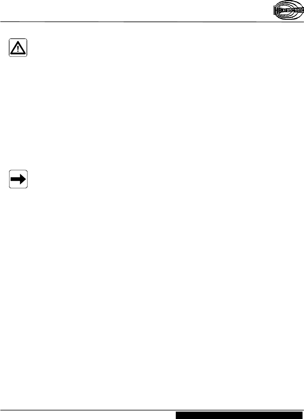
Indicates safety relevant passages
You will find this pictograph as an indicator for occupational safety measures. The neglecting of
such measures poses a serious hazard.
Always observe the instructions and be particularly attentive and careful.
Avoid any situations that could at any time be a danger to persons or machines.
Indicates important information
This symbol brings your attention to important information on how to secure a long serviceable life of the
radio telecontrol system.
Pay attention to the comments and instructions given. Ignoring the information provided may permanently
impair the reliability and operability of the equipment.

Operating Instructions
Radio Transmitter PM NTU
Page 6 / 16 BE-PM_NTU-US-L.DOC [ Word 97 ] FL
HBC-radiomatic, Inc. , Cincinnati , Ohio 45242 , USA
2000-08-16 Information and specifications subject to change without notice.
Radio Control System
2.2 General Safety Instructions
Radio telecontrols facilitate and increase the operating efficiency of construction cranes.
Nevertheless, the operator must thoroughly understand and be in a position to properly use a radio
system !
Important information :
Modifications made to this device, not expressly approved by the manufacturer may void the users
authority to operate this device !
Ø Read the Operating Instructions Manual carefully and thoroughly before working with the radio
transmitter for the first time !
Ø The operator undertakes to strictly adhere to the instructions and proceedings described in this
manual as well as follow the general rules and regulations for worker safety and accident
prevention. Ignoring any such instructions or regulation could pose a fatal threat to the operator
or others.
Ø Keep this manual on location and readily available at all times !
Ø Only authorized and properly trained personnel may operate the radio transmitter.
Ø Anyone who is under the influence of drugs, alcohol or medications that have a negative effect
on a person's reactions may at no time commission, operate, maintain or repair the radio
transmitter.
Ø Before switching the radio transmitter ON ensure that no-one is or can be endangered by the
initiated operation.
Ø With the first signs of any malfunction related to the operative safety and reliability of the
PM NTU radio transmitter the operator must immediately shut down or not activate the
transmitter. For the purpose of the present manual "shut down" implies :
– switching OFF the transmitter,
– storing the transmitter in a safe place and ensuring no unauthorized access,
– de-energizing the receiver and
– unplugging the connection cable on the receiver !
Ø Defects must be repaired and objects of interference must be removed immediately !
Ø Only qualified and competent personnel are permitted to repair a defective transmitter. Use
original HBC spare parts only ! The use of any other spares will render the technical
inspectorate approval invalid as well as substantially impede operative safety.
Ø Observe all periodical tests and inspections that are required by law or recommended in the
present operating instructions !
Ø When using the PM NTU radio transmitter always observe the regulations and instructions
stipulated in the authoritative worker's safety and accident prevention regulations (e.g. VBG 9).
– The PM NTU radio transmitter has been manufactured in accordance with the regulations
and guidelines stipulated in the German Trade Association's "Safety and Accident
Prevention Regulations for Operating Cranes by Radio Telecontrols" (VBG 9) and
pr EN 12077-1.
– The PM NTU radio transmitter has been tested and approved in accordance with EMC
guidelines and complies with the authoritative standards for emitted interference and
interference immunity.
Ø Use the transmitter carefully and solely for its intended use. In particular when using a
transmitter to telecontrol a crane for the first time.
Operating Instructions
Radio Transmitter PM NTU
BE-PM_NTU-US-L.DOC [ Word 97 ] FL Page 7 / 16
HBC-radiomatic, Inc. , Cincinnati , Ohio 45242 , USA
Information and specifications subject to change without notice. 2000-08-16
Radio Control System
2.3 Operator Safety Instructions
Ø Before beginning crane operation, position yourself so that you have a clear and complete
overview of the working radius of the crane or machine.
Ø Depending on your angle or position to the crane or machine, the transmitter control commands
“trolley left” and “trolley right” appear to interchange! It is essential that you take your
bearings to the crane or machine into due consideration before operating equipment.
Ø In case of an emergency or any disturbances within the working range of the crane or machine,
switch the transmitter off immediately by actuating the STOP switch. Should the transmitter
show signs of technical failure or breakdown, disconnect the radio system immediately !
Ø Always switch OFF the transmitter during breaks and after finishing work to avoid operating
errors or any accidental actuation of operator control elements.
– These precautions are particularly important whenever changing your position or climbing
over an obstacle.
Ø Never leave an activated transmitter unattended. The operator undertakes to follow and comply
with the authoritative regulations for worker safety and accident prevention (e. g. VBG 9).
Note :
In the event of an interruption of the radio link during a working cycle – what can occasionally
happen – both transmitter and receiver automatically shut down (so-called "compulsory switch-
off").
To reactivate the system the you must release all operator controls, such as pushbuttons or momentary
contacts, and allow the control elements to return to their zero position. Reactivate the radio system by
pressing the "ON/OFF" toggle switch. The system must be reactivated before the crane or machine can
react to control commands ! This feature hinders any uncontrolled or unwanted crane or machine
movement, should the radio link be interrupted.
When operating a crane by means of a radio telecontrol system for the first time, you may miss
the physical contact to the crane that you were used to in the operating stand. As you are no
longer in the crane and can no longer sense the starting of the crane movements as distinctly,
crane reactions appear sluggish or dull.
Operating Instructions
Radio Transmitter PM NTU
Page 8 / 16 BE-PM_NTU-US-L.DOC [ Word 97 ] FL
HBC-radiomatic, Inc. , Cincinnati , Ohio 45242 , USA
2000-08-16 Information and specifications subject to change without notice.
Radio Control System
3Operating Instructions
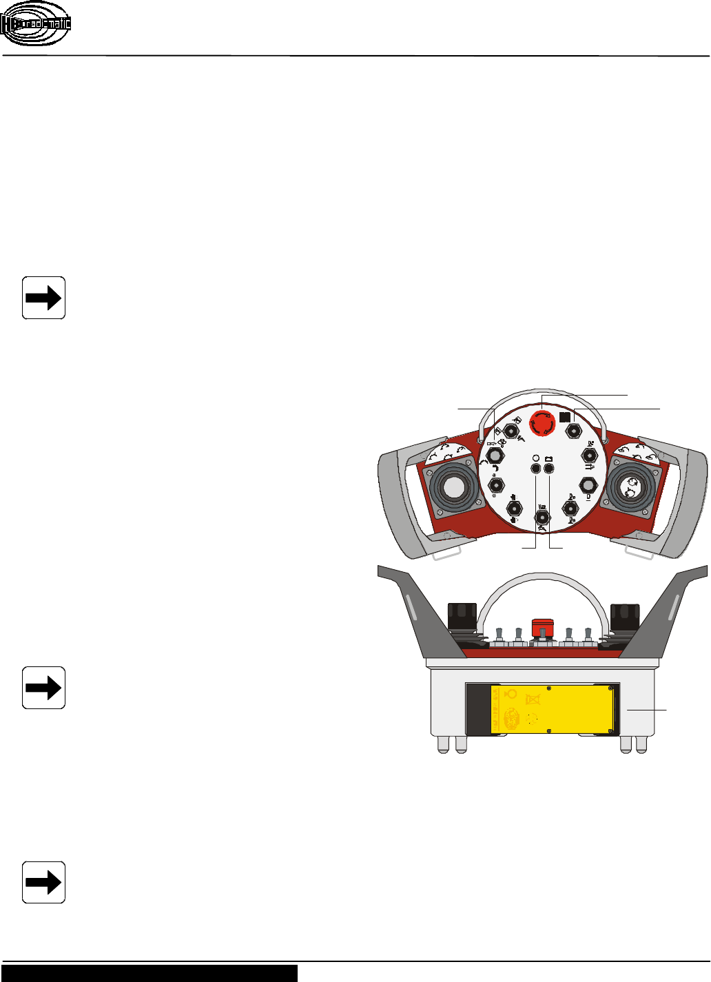
1. Before commissioning the transmitter or initial operation, insert a fully charged FuB 10 AA
battery into battery compartment (pos. À) on the back of the transmitter (inscription must be
visible). The battery supplies the necessary working voltage (6 V DC).
2. Turn STOP switch (pos. Á) to the right to unlock.
3. Switch ON transmitter and crane or machine with "ON/OFF" toggle switch (pos. Â).
The green LED (pos. Ã) begins to flash, i.e. the transmitter is operable.
Important information :
After switching ON the transmitter and before operating the crane or machine you must always :
– trigger the acoustic signal by pressing the "Horn" pushbutton (pos. Å). This warns all
colleagues that the crane or machine is about to move;
– test the operativeness of the STOP switch.
After switching ON the transmitter the
instrument indicates a successful radio link
to the receiver when the red LED
"RF/H.F./AF/RF" darkens and the green
LED "Si 1" lights up (confer control light
panel on receiver). The radio telecontrol
system is ready for use. The operator can
now issue control commands using the
transmitter control elements.
Whenever the battery is nearly empty, the
red LED (pos. Ä) lights up or an acoustic
signal sounds. Replace the drained battery
with a fully charged battery immediately
and insert into the battery charger for
recharging (confer chapter "Battery and
Battery Charger" for further details).
Note :
The transmitter will automatically switch
OFF within a few minutes if the operator
fails to replace the drained battery.
Should the operator – intentionally or unintentionally – switch off the transmitter with the STOP
switch, proceed as follows to re-start the transmitter :
1. Switch transmitter OFF with the "ON / OFF" toggle switch (pos. Â).
2. Turn STOP switch (pos. Á) to the right to unlock;
3. Switch transmitter ON again with the "ON / OFF" toggle switch.
Note :
Always use the "ON / OFF" switch to switch the transmitter ON or OFF. Do not use the STOP
switch !
File: PM-NTU-Inbetriebnahme [ CorelDRW 8.0 ] 11.08.2000 FL
rpm
rpm
I0
File: PM-NTU-Rueckseite.CDR [ CorelDRW 8.0 ] 23.06.2000 FL
HBC-electronic
Funktechnik GmbH
Tel.: +49(0)7951/393-0
Made in Germany
Prod.Code: SNTU 1.0
Transmitter Ser.No.: 735-
IP55 / Nema 4 U: 6V DC
Frequency Band (MHz): 902 918
W5 : FB1
FCC-ID: NO9 SNTU04
Batt.
–
Micron: 2977102872
Eco: 2977102873
Spec.: 2977102874
Orbit: 29771021314
SNTU: 29771021290
CAN
Micron: NO9M30004
Eco: NO9E10004
Spec.: NO9S10004
Orbit: NO9O10004
Patrol: NO9P10004
SNTU: NO9SNTU04
PMNTU: N09PMNTU4
USA
– 6V + + 6V –
Ni-CdCd
Å
Á
Â
ÄÃ
À
Operating Instructions
Radio Transmitter PM NTU
BE-PM_NTU-US-L.DOC [ Word 97 ] FL Page 9 / 16
HBC-radiomatic, Inc. , Cincinnati , Ohio 45242 , USA
Information and specifications subject to change without notice. 2000-08-16
Radio Control System
3.1 Battery and Battery Charger
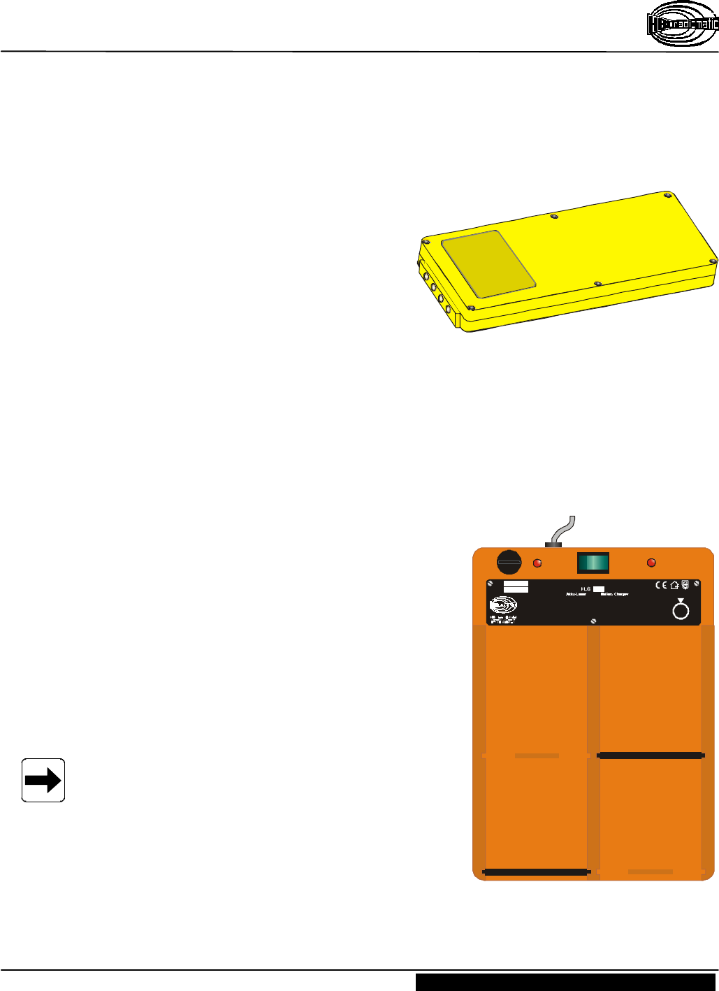
3.1.1 FuB 10 AA Transmitter Battery
The age and ambient temperature are decisive for
the effectiveness of the battery charge. Older
batteries lose capacity over time. Temperatures
under zero also have a negative effect on battery
charge.
The length of serviceable battery life depend on
how the battery is treated. When handled
properly the FuB 10 AA battery can exceed 500
charging cycles. Do not totally discharge or
short-circuit contacts as this can permanently destroy the battery.
We recommend recharging the battery only when it is empty, i.e. when the red LED blinks or an
acoustic signal sounds. Always store rechargeable batteries at room temperature.
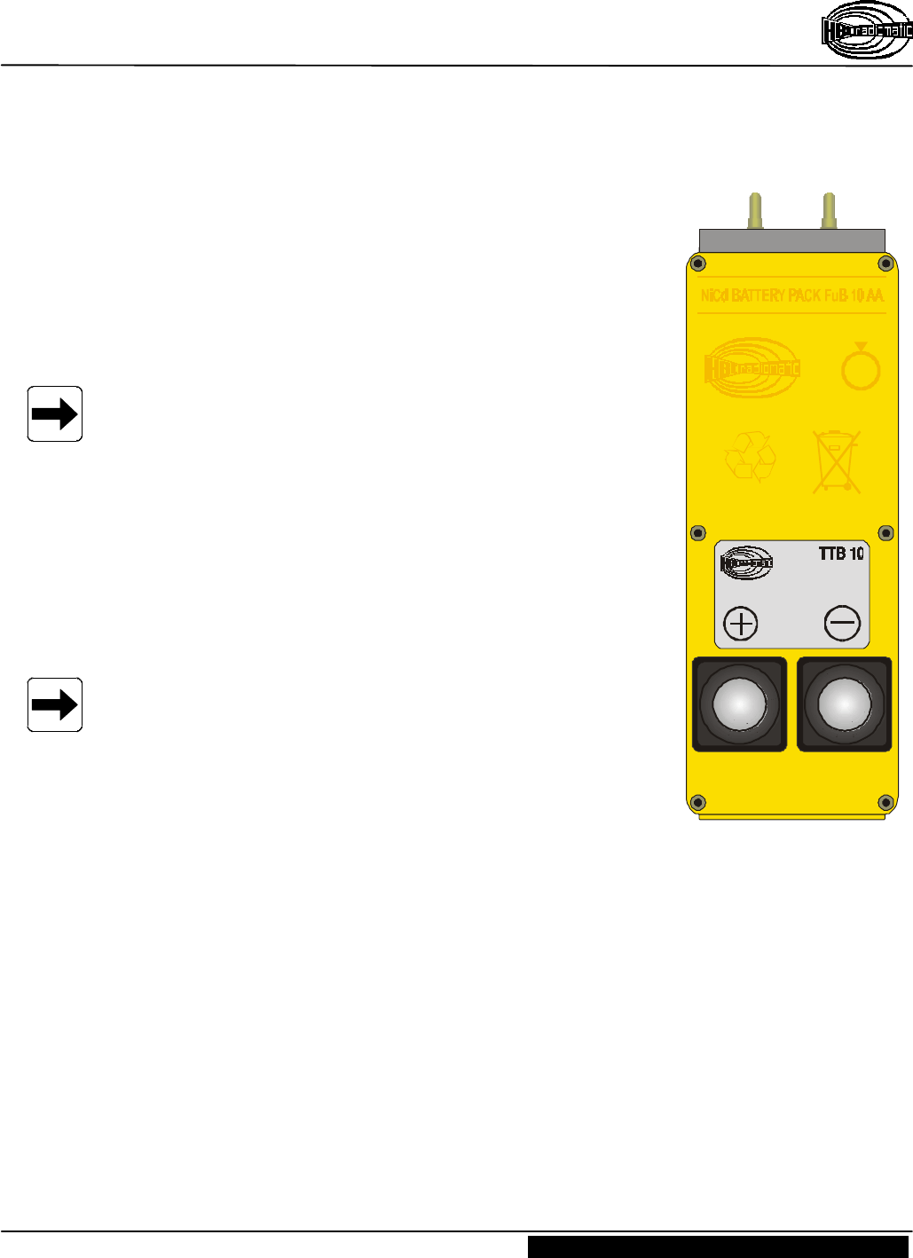
3.1.2 FLG 102 Battery Charger
Recharging batteries
1. Connect battery charger to mains (confer nameplate
on battery charger for details).
2. Switch ON the battery charger.
3. Insert battery with the type plate facing up into the
battery compartment (pos. Á).
Charging indicator (red LED ; pos. ÀÀ )
LED lit:.................................... battery charging.
LED off or flashing: ................ battery full, i.e. operable.
LED flashes when
inserting battery: ...................... battery totally discharged
or defective.
Note :
– A discharged FuB 10 AA battery recharges in
approx. 4 hours. Intelligent electronics in the
battery charger ensure that charging does not
exceed 5 hours.
– Only quick charge NiCd batteries at temperatures
between 50 °F and 104 °F (+10 °C and +40 °C).
– Protect battery contacts against short circuits.
Never store batteries in tool box or trousers pockets. A key chain can short the battery.
Always use the protective cap included.
– Use the charger at room temperature and protect it from extreme heat (direct sun).
EIN/ON AUS/OFF
Lg.Nr. 31.14
Betriebsanleitung beachten !
Akku einlegen.
Dauerlicht: Akku wird geladen.
Blinken: Akku entnehmen.
Vor Öffnen des Gerätes Stecker ziehen !
Ladung nur bei Zimmertemperatur !
Insert battery.
Steady light: Charging.
Blinking light: Remove battery.
See operating instructions !
Unplug unit before opening for service !
For room temperature only !
À À
Á
Á

Operating Instructions
Radio Transmitter PM NTU
Page 10 / 16 BE-PM_NTU-US-L.DOC [ Word 97 ] FL
HBC-radiomatic, Inc. , Cincinnati , Ohio 45242 , USA
2000-08-16 Information and specifications subject to change without notice.
Radio Control System
3.2 Special Operating Modes (Optional)
This chapter describes special operating modes that are not available with all crane systems.
If your radio telecontrol system is not equipped with the features described, you may ignore the
following and continue with the next chapter.
3.2.1 Scanner
With the option scanner, the transmitter and the receiver are equipped with 4 radio frequencies each
(refer to wiring diagrams).
If the radio channel used is currently occupied by another operator, another radio channel may be
selected via a rotary switch. The scanner in the receiver will automatically follow the transmitter to
the radio frequency selected.
After switching ON the transmitter (STOP switch unlocked ; confer to chapter 3) or after a
frequency change during operation, it will last only a short time until the receiver has "followed"
the transmitter to the frequency selected.
Operating Instructions
Radio Transmitter PM NTU
BE-PM_NTU-US-L.DOC [ Word 97 ] FL Page 11 / 16
HBC-radiomatic, Inc. , Cincinnati , Ohio 45242 , USA
Information and specifications subject to change without notice. 2000-08-16
Radio Control System
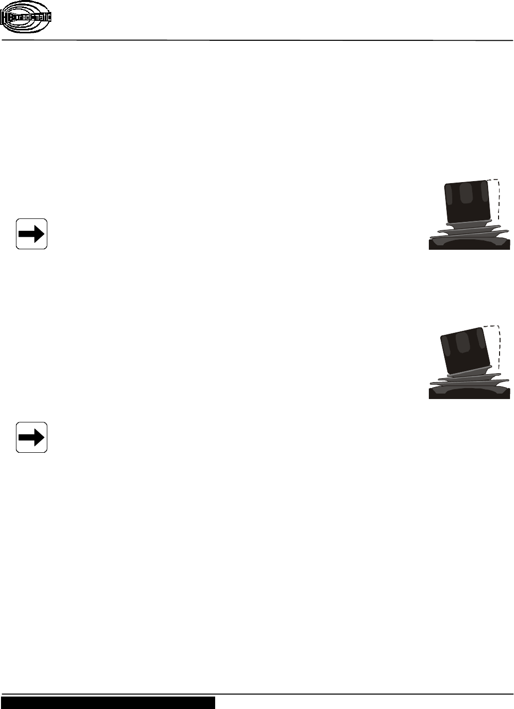
3.2.2 tele-teach-in Battery (TTB 10)
The PM NTU radio control – together with the FSE 735 and FSE 770
radio receivers – features the so-called tele-teach-in option. This
specific function allows you to input and store the minimum as well
as maximum speeds assigned to the individual joystick functions in a
simple manner.
The tele-teach-in option is available for all proportional functions
(joystick commands).
Important note !
Your radio control system was already adapted to your specific
crane by a retailer respectively the manufacturer.
Should the crane movements nevertheless be executed in a jerky
manner or too fast, then please contact your retailer or the
manufacturer in order to have the settings adapted.
In the following, the programming of the minimum and maximum
speeds of the individual control functions will be described by means
of tele-teach-in.
The programming keys ("+" and "–") are located on the tele-teach-in
battery (confer fig. right).
Note :
Please read the instructions at hand completely and carefully
before beginning with the programming !
File: TTB10.CDR [ CorelDraw 8.0 ] 11.08.2000 FL
– 6V + + 6V –
Ni-Cd Cd
Operating Instructions
Radio Transmitter PM NTU
Page 12 / 16 BE-PM_NTU-US-L.DOC [ Word 97 ] FL
HBC-radiomatic, Inc. , Cincinnati , Ohio 45242 , USA
2000-08-16 Information and specifications subject to change without notice.
Radio Control System
Programming
1. Switch OFF the transmitter.
2. Insert a charged tele-teach-in battery (TTB 10) into the transmitter.
3. Depress the programming keys "+" and "–" simultaneously and then switch ON the transmitter.
Keep the programming keys depressed until the green service LED of the transmitter starts
flashing quickly. Now, the control is in the tele-teach-in mode.
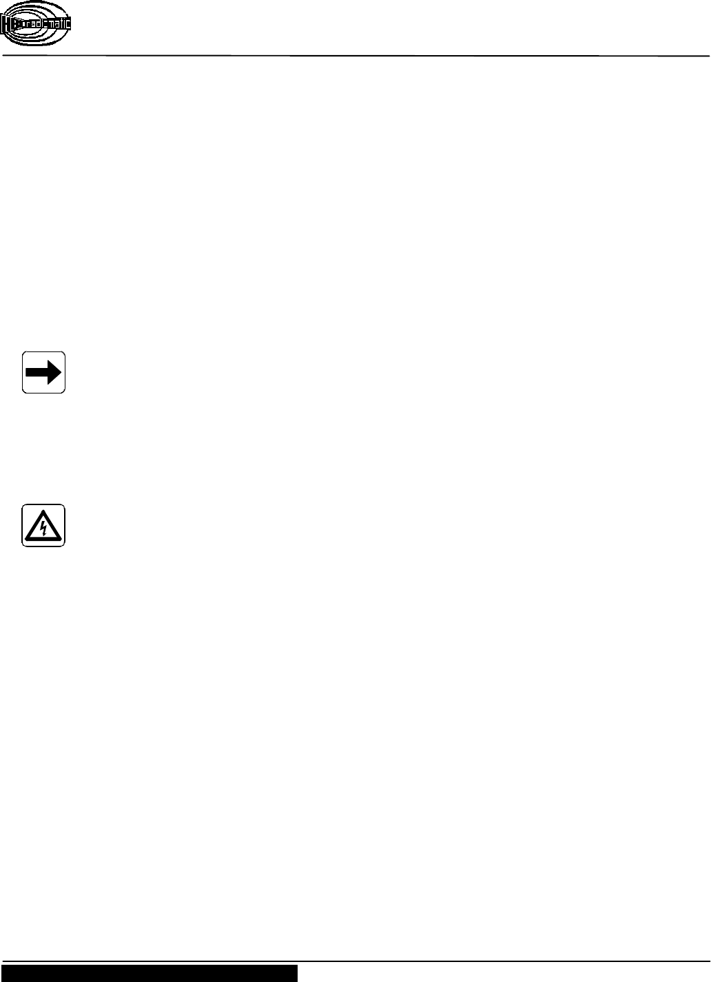
4. Setting the minimum speed (fig. right)
Push the joystick toward the desired function.
Note :
Do not move the lever of the joystick beyond 50% of the maximum lever
travel.
Then adjust the minimum speed by means of the "+" and "–" keys, i.e. by looking for the
minimum point when the hydraulic valve begins to react. It will be helpful to observe the way
the function is carried out as well as the movement of the lever of the hydraulic valve (fig.
above).
5. Setting the maximum speed (fig. right)
Push the joystick toward the desired function by moving it to its end
position. Then adjust the maximum speed by means of the "+" and "–"
keys, i.e. by looking for the maximum point when the hydraulic valve
begins to react. In order to make use of the full lever travel of the
joystick, do not actuate the "+" key any longer after the hydraulic valve
has reached its maximum travel (fig. right).
Note :
In the tele-teach-in mode, only execute one single function at the time, not both joysticks in a
diagonal way, as it is only possible to program one single function at the time.
For all further joystick functions, please repeat the steps beginning with item 3.
In order to verify the programmed settings, switch OFF the transmitter and then switch it ON
afterwards. Now, the transmitter is again in the normal operating mode.
In case of systems that offer creeping function, all the functions will have to be programmed again
in the creeping mode (switch set to the snail symbol).
min.
max.

Operating Instructions
Radio Transmitter PM NTU
BE-PM_NTU-US-L.DOC [ Word 97 ] FL Page 13 / 16
HBC-radiomatic, Inc. , Cincinnati , Ohio 45242 , USA
Information and specifications subject to change without notice. 2000-08-16
Radio Control System
4Trouble-Shooting
Note :
Check the functions with the cabin or the cable control unit first !
Trouble Possible Cause Remedy
No reaction whenever the
transmitter is switched ON. − No operating voltage is
present. − Check the battery contacts for
damage or contamination.
− Insert a fully charged battery in
battery compartment.
− Recharge battery.
Low-power indicator blinks
after minimal operating time,
i.e. red LED illuminates.
− The battery contracts are
contaminated or damaged.
− The battery is not charged.
− The battery is defective.
− Check battery contacts for
damage or contamination.
− Fully recharge battery.
− Ensure that recharging process
runs correctly.
− Check transmitter functions
using a fully charged or
replacement battery.
Operating Instructions
Radio Transmitter PM NTU
Page 14 / 16 BE-PM_NTU-US-L.DOC [ Word 97 ] FL
HBC-radiomatic, Inc. , Cincinnati , Ohio 45242 , USA
2000-08-16 Information and specifications subject to change without notice.
Radio Control System
5Maintenance
The radio system is largely maintenance-free. The following items should nevertheless be taken into
account :
Ø Make sure that the STOP switch moves easily.
Dirt of any kind may interfere with the operation of the switch or even render it impossible.
Ø Inspect the rubber bellows of the compact joysticks regularly for leak-tightness.
Replace immediately if cracks appear since the penetration of dirt and humidity may damage
the function of the compact joysticks.
Ø The batteries of the transmitter should be completely discharged and charged again on a regular
basis.
Ø Never "clean" the transmitter with a pressure or with a steam cleaner.
If necessary, clean it with a fine brush or soft cloth, please.
Note:
In the event of any problems with the radio system, contact your distributor or HBC-radiomatic,
Inc. .
5.1 In The Event of a Fault
Warning:
Never operate a crane or machine with a faulty or defective radio system.
Ø Never try to repair the radio receiver electronics! Opening the transmitter housing terminates
the manufacturer guarantee.
– Send any defective or faulty equipment to you local distributor or to the manufacturer.
They are experts and have the necessary know-how and OEM spare parts.
– Always send transmitter and receiver and enclose a detailed description of the problem.
– Do not forget to enclose your address and telephone number so that we can get in touch
with you quickly if necessary.
Ø To avoid damage during transport, use the original packing supplied with the transmitter and
receiver, otherwise pack securely. Send the consignment to your distributor or to the following
address :
HBC-radiomatic , Inc.
4480 Lake Forest Drive, Suite 306
Cincinnati, OH 45242, USA
Telephone : ................ ( 513 ) – 7 33 – 49 00
Fax : .......................... ( 513 ) – 7 33 – 49 03
Ø Should you decide to personally return a defective radio system to your distributor or
HBC-radiomatic , Inc., then please make an appointment first.
Operating Instructions
Radio Transmitter PM NTU
BE-PM_NTU-US-L.DOC [ Word 97 ] FL Page 15 / 16
HBC-radiomatic, Inc. , Cincinnati , Ohio 45242 , USA
Information and specifications subject to change without notice. 2000-08-16
Radio Control System
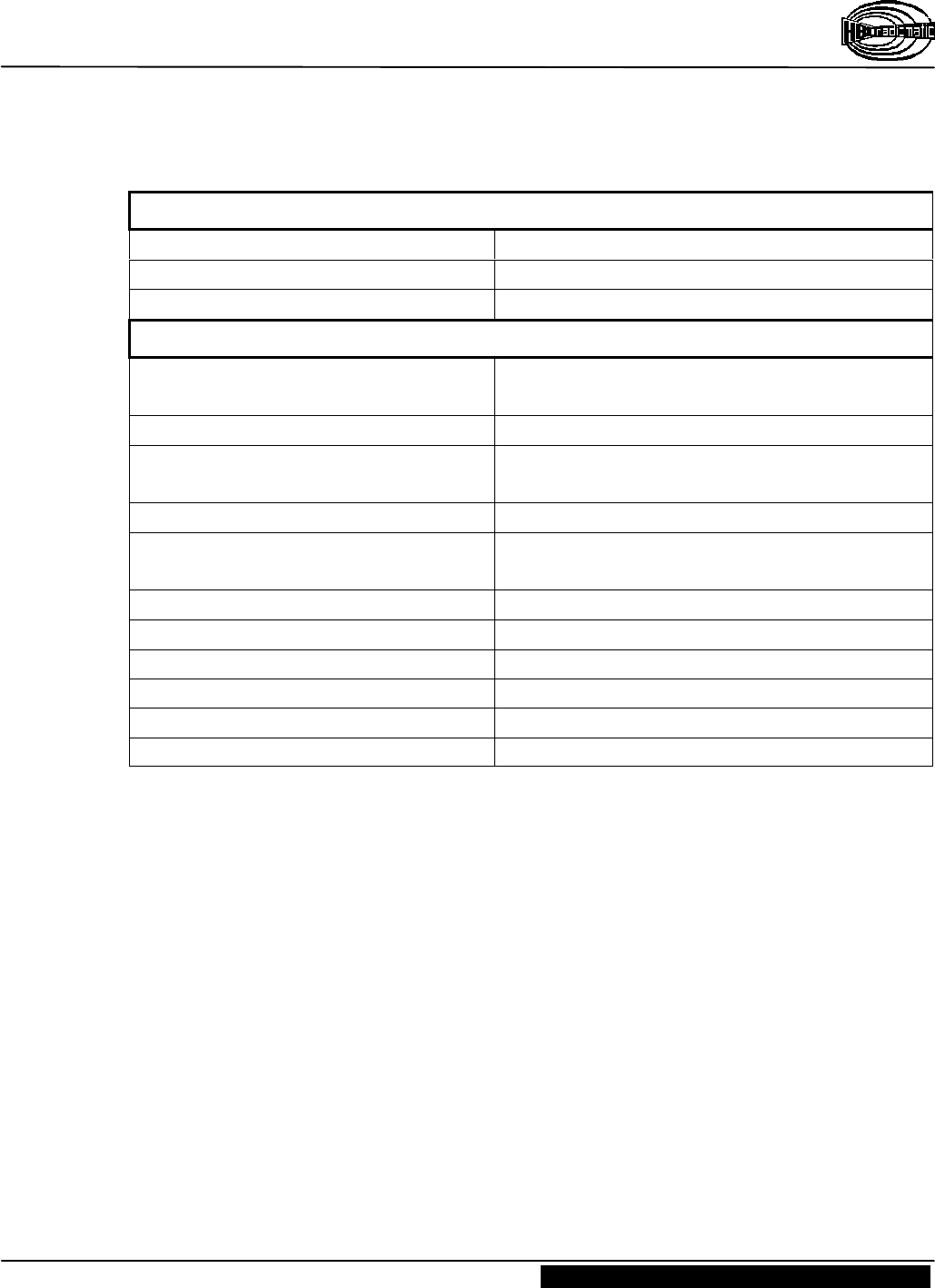
6 Technical Data
General Technical Data
System PM NTU
Max. number of control commands 32 digital or 8 analog + 24 digital
Unique system addresses over 65,000 combinations
Transmitter-specific Technical Data
Transmitting power FuS 671/3 :
FuS 680/3 :
< 10 mW ( synthesizer )
< 5 mW ( synthesizer )
Transmitter antenna Internal
Battery type FuB 10 AA ( yellow , NiCd )
TTB 10 ( yellow )
Power supply with NiCd battery 6 V DC / 1200 mAh
Battery charge at 50 % duty cycle :
at 100 % duty cycle :
16 hours
8 hours
Operating temperature range –13 °F to +167 °F ( –25 °C to +75 °C )
Housing material glass-fiber reinforced plastic
Housing color grey
Dimensions 9.8 x 2.5 x 2.0 " ( 255 x 64 x 50 mm )
Weight approx. 7.7 lb. ( 3,5 kg )
System of protection Nema 4 ( IP 55 )
Operating Instructions
Radio Transmitter PM NTU
Page 16 / 16 BE-PM_NTU-US-L.DOC [ Word 97 ] FL
HBC-radiomatic, Inc. , Cincinnati , Ohio 45242 , USA
2000-08-16 Information and specifications subject to change without notice.
Radio Control System
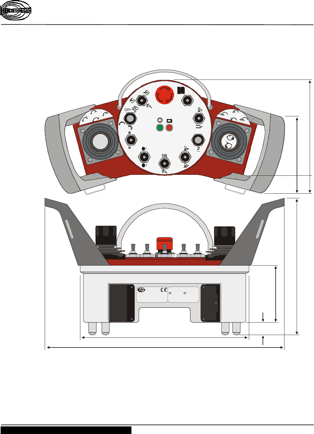
6.1 Dimensions of the PM NTU
rpm
rpm
I0
HBC-electronic
Funktechnik GmbH
Tel.: +49(0)7951/393-0
Made in Germany
Prod.Code: SNTU 1.0
Transmitter Ser.No.: 735-
IP55 / Nema 4 U: 6V DC
Frequency Band (MHz): 902 918
W5 : FB1
FCC-ID: NO9 SNTU04
Batt.
–
Micron: 2977102872
Eco: 2977102873
Spec.: 2977102874
Orbit: 29771021314
SNTU: 29771021290
CANMicron: NO9M30004
Eco: NO9E10004
Spec.: NO9S10004
Orbit: NO9O10004
Patrol: NO9P10004
SNTU: NO9SNTU04
PMNTU: N09PMNTU4
USA
264 mm (10.4 ")
420 mm (16.5 ")
210 mm (8.3 ")
85 mm (3.3 ")
15 mm
(0.6 ")
File: PM-NTU-Dimensions&OPControls.CDR
[ CorelDRW 8.0 ] 14.08.2000 FL
131 mm (5.2 ")
ca. 140 mm (5.5 ")