HBC radiomatic SPECTRUMD Remote Control User Manual spectrum D
HBC-radiomatic GmbH Remote Control spectrum D
UserManual.wiki
>
HBC radiomatic
>
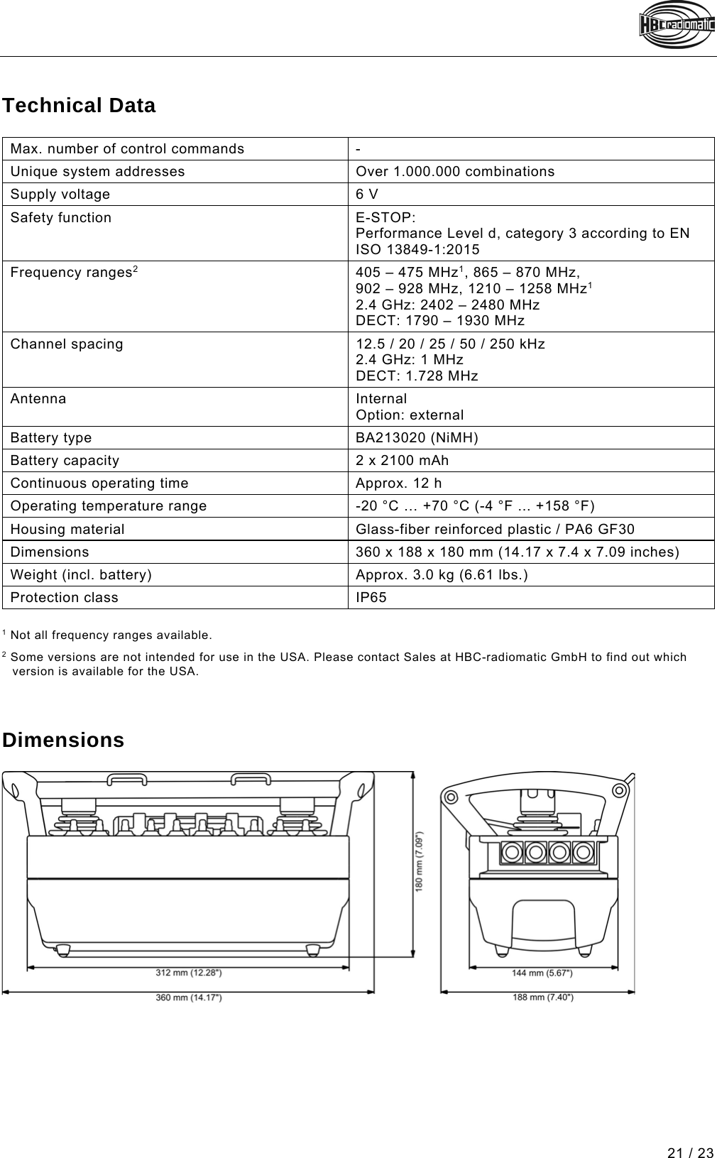
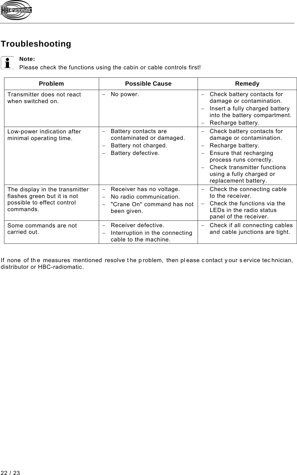
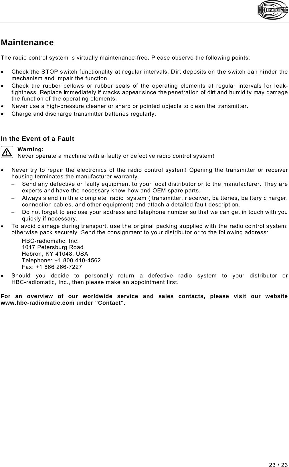
SPECTRUMD User Manual
user manual
Navigation menu
Upload a User Manual
Namespaces
Wiki Guide
HTML
PDF
Info
Views
User Manual
Discussion / Help
Navigation