HBC radiomatic SPECTRUMD Remote Control User Manual spectrum D
HBC-radiomatic GmbH Remote Control spectrum D
user manual
spectrum D
Operating Instructions
Original Operating Instructions
2 / 23
Pos: 3 /Technische Doku mentation/Betriebsa nleitungen/Al lgemein/1. Seite BA @ 1\mod_122088365 0953_48.docx @ 30158 @ @ 1
Table of Contents
Safety Instructions ................................................................................................................................... 3
Intended Use .................................................................................................................................... 3
Safety Instructions for Installation and Operation ............................................................................... 3
FCC Notes ....................................................................................................................................... 4
Modification of Equipment ..................................................................................................... 4
RF Exposure Statement ........................................................................................................ 4
Operation ................................................................................................................................................. 5
Activating the Transmitter ................................................................................................................. 5
Deactivating the Transmitter ............................................................................................................. 6
Automatic Power Off (APO) Function ................................................................................................. 6
Display ............................................................................................................................................ 7
Battery and Battery Charger ..................................................................................................................... 8
Charging the Battery ....................................................................................................................... 10
Options ................................................................................................................................................... 11
Safety Features .............................................................................................................................. 11
Frequency Management ................................................................................................................. 14
Catch-Release ............................................................................................................................... 15
Tandem Operation .......................................................................................................................... 16
Catch-Release-Tandem Operation................................................................................................... 18
Cable Control ................................................................................................................................. 19
RF-amplifier ................................................................................................................................... 19
Utilization of Button as Shift Key ................................................................................................. 19
Pre-selection of Trolley or Hoist ...................................................................................................... 19
Feedback by LED ........................................................................................................................... 19
Bank Switch ................................................................................................................................... 19
Rotary Switch for Pre-selected Speed ............................................................................................. 20
Transmitter Key Up ......................................................................................................................... 20
radiomatic® CPS ............................................................................................................................. 20
radiomatic® iBAR ............................................................................................................................ 20
Slewing Gear Release .................................................................................................................... 20
Technical Data ........................................................................................................................................ 21
Dimensions ............................................................................................................................................ 21
Troubleshooting ..................................................................................................................................... 22
Maintenance ........................................................................................................................................... 23
Attachments: System specific views, circuit diagrams and / or output wiring.
Pos: 4 /Technische Doku mentation/Betriebsa nleitungen/Al lgemein/----- Seitenumbruch ------ @ 1\mod_121967232 6234_0.docx @ 29509 @ @ 1
Pictographs
Danger due to electrical voltage. Touching live parts inside the unit can be f atal or cause serious
injuries.
Instructions for occupational health and safety. Not following these instructions can lead to
accidents
that can cause damage, serious injuries or even death.
Important information about the operation of the radio system.
Manufacturer:
HBC
-radiomatic GmbH • H aller S traße 45 – 53 • 74 564 C railsheim • Germany • T el. + 49 7 951 39 3-
0 • i nfo@radiomatic.com.
HBC
-radiomatic GmbH is not liable for any misprints or errors!
®
radiomatic and radiobus are registered German trademarks.
©
17 / 2017, HBC-radiomatic GmbH, 74564 Crailsheim, Germany
No part of this doc ument m ay b e r eproduced i n any m anner w hatsoever w ithout the e xpressed w ritten permission of
HBC
-radiomatic GmbH.

3 / 23
Pos: 5 /Technische Doku mentation/Betriebsa nleitungen/Al lgemein/Sicherheits hinweise @ 3\mod_124540602 2438_48.docx @ 45208 @ 122 @ 1
Safety Instructions
Read these operating instructions carefully before working with the radio system. This applies in particular
to the installation, commissioning and maintenance of the radio system.
The operating instructions are a constituent part of the radio control system and must always be kept close
at hand for the responsible personnel.
The term ‘machine’ is used in the operating instructions for the different possible uses of the radio system.
Intended Use
• The radio system is used for the control of machines and for data transfer. Observe the occupational
safety and accident prevention regulations applicable to each application.
• The intended use also includes reading the operating instructions and adhering to all safety information
contained therein.
• The radio system must not be used in areas where there is a risk of explosion, nor for the control of
machines used to convey persons, unless it is explicitly approved for these uses by the manufacturer.
• Modifications to the radio system may only be carried out by specialist personnel who h ave been
trained and authorized by HBC-radiomatic. All modifications must be documented at the factory in the
radio control master file.
• The safety dev ices of t he radio c ontrol s ystem m ust not b e m odified, removed o r bypassed. In
particular, modifications to any part of the radio system's complete E-STOP system are not allowed.
Safety Instructions for Installation and Operation
• The electrical connection according to the enclosed output wiring diagram must be established by a
qualified electrician exclusively.
• The r eceiver m ay onl y b e ope ned by tr ained p ersonnel. C omponents i nside the receiver can be
energized at l ife-threatening v oltages. T he s upply v oltage fo r the m achine m ust b e disconnected
before the receiver is opened.
• Please also note that, with radio systems, the presence of persons in the danger zone – in particular
beneath the load (cranes!) – is prohibited in all cases.
• Select a safe location for radio control, from which you have a good and complete view of the working
movements of the machine, the load movements and the surrounding working conditions.
• It is not permissible to leave a radio transmitter unattended when it is activated. Always switch off the
radio transmitter when it is not required. This applies in particular if you change location, when working
without radio control, during breaks and at the end of work. Always protect the radio transmitter against
use by unauthorized persons, for example by locking it away.
• In the event of an e mergency an d w ith all fa ults, s witch off t he radio transmitter i mmediately by
pressing the STOP switch.
• Only operate the radio system when it is in perfect working order. Faults and defects that could
influence s afety must be r ectified by s pecialists w ho have b een tr ained and auth orized by H BC-
radiomatic before the system is put back into operation.
• Note th at th e o perational di rections of the o perating el ements m ay app ear i nverted d epending on
location and viewing angle to the machine. This applies in particular to rotary cranes if your location
changes from inside to outside the radius of the crane. The operator must make himself familiar with
the directional markings on the machine before starting to work.
• Repairs may only be carried out by specialist personnel who have been trained and authorized by
HBC-radiomatic. U se o riginal replacement pa rts and accessories (e.g. rechargeable batteries)
exclusively; otherwise it is possible that the equipment safety can no longer be guaranteed and our
extended warranty will be voided.
• Remain vigilant when working with the radio system and familiarize yourself with its functions. This
applies in particular if you are working with it for the first time or if you work with it only occasionally.
Pos: 7 /Technische Doku mentation/Betriebsa nleitungen/Al lgemein/Sicherheits hinweis STOP/Module/ 1.1 Sicherheitshin weis STOP @ 4\mod_1261040631189 _48.docx @ 54510 @ @ 1
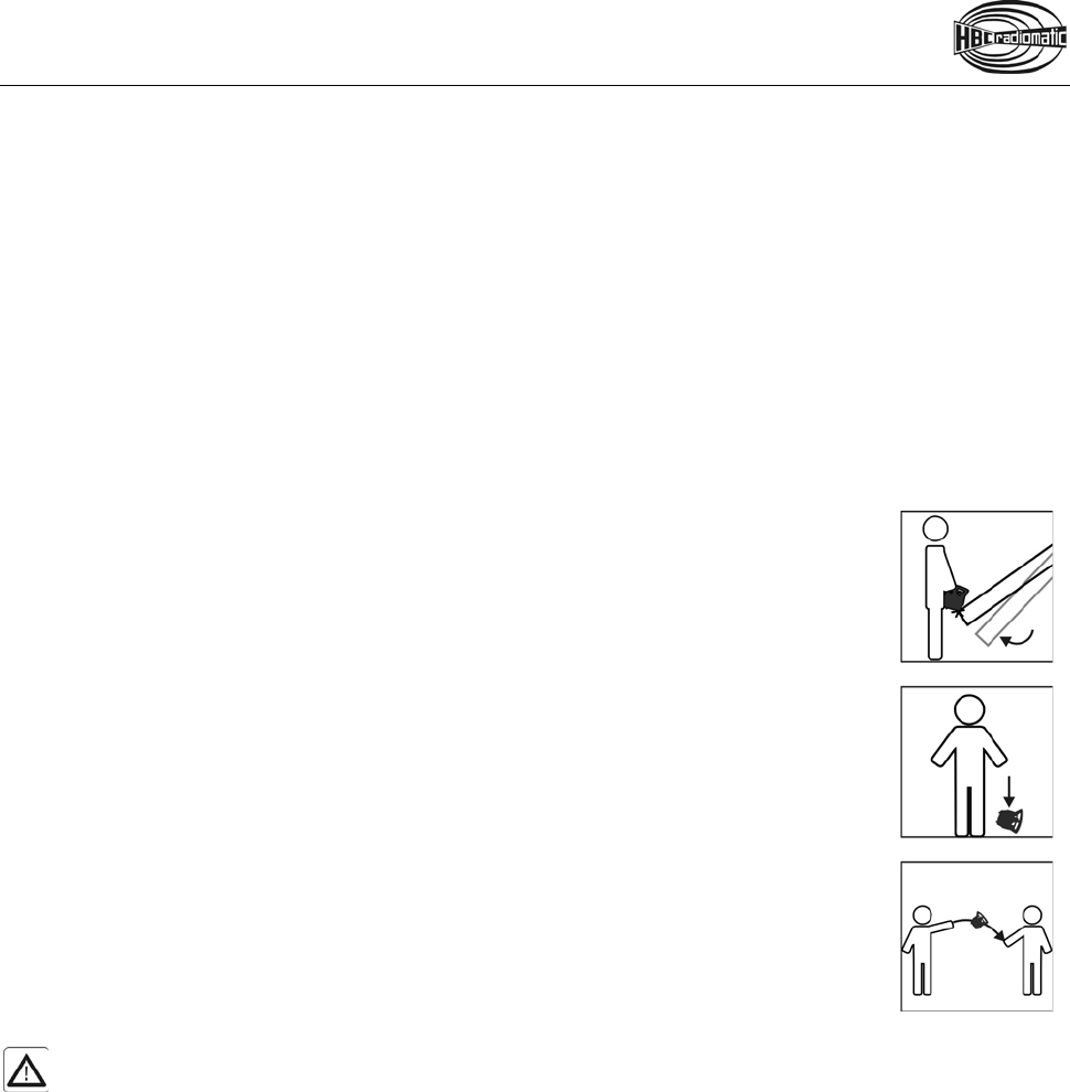
• Before s tarting t o w ork, examine the S TOP switch for m echanical eas e o f m otion a nd el ectronic
function at least once a day:
Pos: 8 /Technische Doku mentation/Betriebsa nleitungen/Al lgemein/Sicherheits hinweis STOP/Module/ 1.2 Sicherheitshin weis STOP mit LED und Di splay @ 2\mod_1229612763796_ 48.docx @ 41067 @ @ 1
When y ou p ress t he S TOP s witch w ith the transmitter o n, th e status LED an d the di splay of the
transmitter have to go out. If the status LED and the display don’t go out then you have to disable the
radio control system immediately.
Pos: 10 /Technische Dok umentation/Betriebs anleitungen/Al lgemein/Sicher heitshinweis STOP/Module/ 1.3 Sicherheitshi nweis STOP Akku und radiomati c iLOG @ 3\mod_1259048767123_ 48.docx @ 53180 @ @ 1
Remove the battery and the radiomatic® iLOG from the transmitter and inform a service technician.

4 / 23
15 /Technische Dokumen tation/Betriebsan leitungen/Allge mein/FCC -neu- @ 5\mod_128637 0333083_48.docx @ 63749 @ @ 1
FCC Notes
Modification of Equipment
Changes or modifications made to this equipment no t expressly approved by the party responsible for
compliance may void the FCC authorization to operate this equipment.
RF Exposure Statement
This d evice c omplies w ith the R F e xposure S AR tes t ex clusion r equirements fo r p ortable d evices.
However, the device shall be used in such a manner that the potential for human contact during normal
operation is minimized.
Pos: 15 /Technische Dok umentation/Betriebs anleitungen/Al lgemein/----- Seitenumbruch ------ @ 1\mod_1219672326234_0.d ocx @ 29509 @ @ 1
5 / 23
Pos: 16 /Technische Dok umentation/Betriebs anleitungen/Send er/Bedienung/Modul e/_Ü1 - Bedienung @ 2\mod_1225 284257125_48.doc x @ 35689 @ 1 @ 1
Operation
Pos: 18 /Technische Dok umentation/Betriebs anleitungen/Send er/Bedienung/Modul e/-1.1- radiomatic iLOG @ 3\mod_1259054956406_48. docx @ 53232 @ @ 1
The transmitter is equipped with an electronic radiomatic® iLOG key. radiomatic® iLOG contains all the
data required for operating the transmitter. Operation is not possible without radiomatic® iLOG!
Depending on the version the radiomatic® iLOG can also be used for operation of replacement transmitters
of identical construction.
Pos: 20 /Technische Dok umentation/Betriebs anleitungen/Send er/Bedienung/Modul e/-1.2- Nullstellung szwang @ 2\mod_1237967536 984_48.docx @ 42910 @ @ 1
When activating the transmitter and if the radio connection is interrupted (e.g. if the connection is lost or
the transmission range is exceeded), the transmitter reacts with the so-called enforced zero-position.
Release all operating elements so they can return to the zero-position and actuate the start button. The
machine w ill no t react i f th e o perating e lements a re not i n zero-position. This prevents uncontrolled
machine movements after the radio connection has been interrupted.
Pos: 22 /Technische Dok umentation/Betriebs anleitungen/Send er/Bedienung/Modul e/_Ü2 - Sender einschal ten @ 2\mod_1225284327093 _48.docx @ 35710 @ 2 @ 1
Activating the Transmitter
Pos: 26 /Technische Dok umentation/Betriebs anleitungen/Send er/Bedienung/Modul e/-2- Einschalten - ec o iLOG/spectrum D @ 4\mod_12670887 46933_48.docx @ 57851 @ @ 1
The steps 3 and 4 need to be carried out within 5 seconds:
1. Insert a charged battery into the battery compartment.
2. Turn the STOP switch to unlock.
3. Shortly actuate the start button and then release. The transmitter will switch off if the button is
pressed for longer than half a second!
4. Actuate the start button again until the status LED flashes green. Then release the button.
The transmitter is now ready for operation.
5. Depending on the application, you must actuate the start button again before movement commands
can be carried out.
Note:
The transmitter switches off
if
•
the start button is pressed for longer than half a second in step 3 of the start sequence.
•
the start sequence (steps 3 and 4) takes over 5 seconds.
•
another button is pressed during the start sequence.
You must then repeat steps 3 and 4 or 3 to 5.
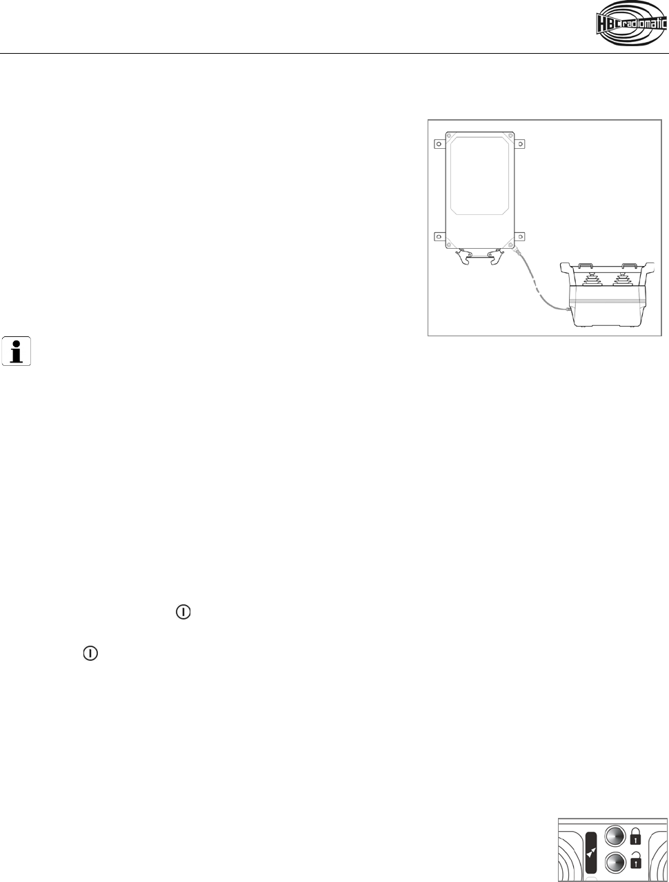
Pos: 36 /Technische Dok umentation/Betriebs anleitungen/Send er/Bedienung/Modul e/-2- Einschalten - spec trum D/E mit Smart Card @ 12\mod_143 2194538609_48.doc x @ 138484 @ @ 1
With merlin® TUC
1. Insert a charged battery into the battery compartment.
2. Turn the STOP switch to unlock.
3. Press the start button.
The status LED flashes green 2 times and red 1 time per second.
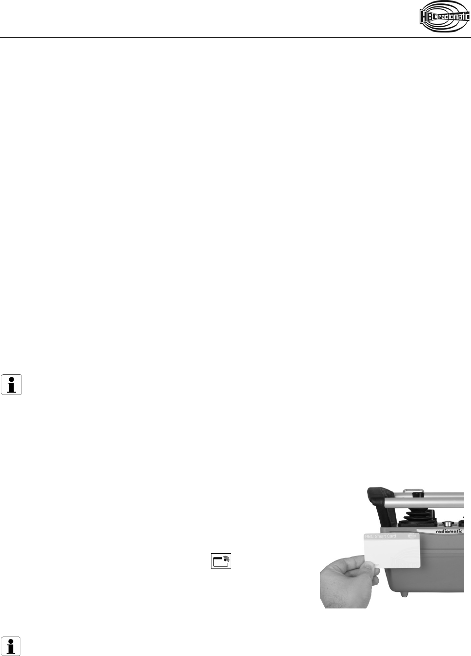
4. Hold the merlin® TUC to the position
on the transmitter marked with this symbol (cf. illustration).
The transmitter vibrates and an acoustic signal sounds.
When the status LED flashes green, the transmitter is ready to
operate.
5. Depending on the application, you must actuate the start button
again before movement commands can be carried out.
Note:
The transmitter can only be activated with a valid
merlin® TUC
. If you use a card that does not match
the respective transmitter or is not approved for this transmitter,
the transmitter vibrates 3 times. At
the same time an acoustic signal sounds. The transmitter is automatically shut down after 2 seconds.
Please contact your superior in such cases.
The transmitter also shuts down if the start sequence is not completed within 10 seconds. In this
case press the start button and repeat the procedure!
Pos: 37 /Technische Dok umentation/Betriebs anleitungen/Al lgemein/----- Seitenumbruch ------ @ 1\mod_1219672326234_0.d ocx @ 29509 @ @ 1

6 / 23
Pos: 38 /Technische Dok umentation/Betriebs anleitungen/Send er/Bedienung/ Module/-3- Achtung - akusti sches Warnsignal @ 2\mod_1225 286721468_48.doc x @ 35796 @ @ 1
Caution:
Before starting work always trigger the acoustic signal. This warns all colleagues that the machine
is about to move.
Pos: 39 /Technische Dok umentation/Betriebs anleitungen/Send er/Bedienung/Modul e/_Ü2 - Sender ausscha lten @ 2\mod_1225284370828 _48.docx @ 35731 @ 2 @ 1
Deactivating the Transmitter
Pos: 40 /Technische Dok umentation/Betriebs anleitungen/Send er/Bedienung/ Module/-4- Ausschalten - STOP-Scha lter @ 2\mod_1225289959765_48. docx @ 35880 @ @ 1
Press the STOP switch.
Pos: 45 /Technische Dok umentation/Betriebs anleitungen/Send er/Bedienung/Modul e/-5- Hinweis - Akku wechsel n (spectrum D) @ 9\mod_134822916 5396_48.docx @ 100044 @ @ 1
Note:
Replace the battery when the battery display illuminates red, an acoustic signal sounds, the status
LED flashes red and the transmitter vibrates (option). Otherwise, the transmitter will switch off in a
few minutes.
Recharge the empty battery in the respective charger.
Pos: 52 /Technische Dok umentation/Betriebs anleitungen/Send er/Bedienung/Modul e/-6.1- APO-Funktion @ 2\mod_122 5288357203_48.doc x @ 35859 @ 2 @ 1
Automatic Power Off (APO) Function
The transmitter is equipped with an a utomatic power off ( APO) function and will automatically shut off
approx. 15 min after the last command input.
The automatic power off serves to increase safety and also saves battery power.
Pos: 54 /Technische Dok umentation/Betriebs anleitungen/Send er/Bedienung/Modul e/-6.2- APO-Funktion Einsc halten @ 3\mod_12595657 74413_48.docx @ 53560 @ @ 1
After an automatic power off, the transmitter must be reactivated as described in the chapter “Operation”.
Pos: 55 /Technische Dokumen tation/Betriebs anleitungen/Send er/Bedienung/Modul e/-6.3- APO-Funktion @ 2\mod_123331 6916250_48.doc x @ 41569 @ @ 1
Caution:
The automatic power off
does not relieve the operator of the responsibility to turn off the
transmitter
with the STOP switch when not in use.
Pos: 57 /Technische Dok umentation/Betriebs anleitungen/Al lgemein/----- Seitenumbruch ------ @ 1\mod_1219672326234_0.d ocx @ 29509 @ @ 1
7 / 23
Pos: 59 /Technische Dok umentation/Betriebs anleitungen/Send er/Display/-1- Display - spectrum D/E @ 6\mod_12989835 10628_48.docx @ 66070 @ 2 @ 1
Display
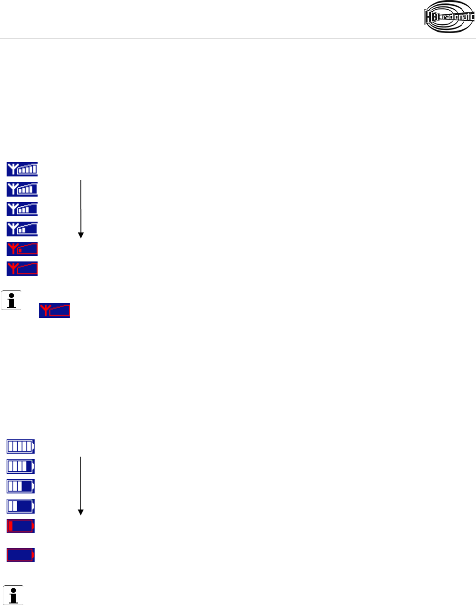
Field strength
The fi eld s trength i ndication p rovides i nformation abo ut the q uality of t he r adio connection. With an
optimum connection, all 5 bars ar e displayed. The fi eld s trength i ndication i s al ways v isible when the
transmitter is turned on.
Field strength is indicated in the following degrees:
Strong received signal
Weak received signal
No signal
Note:
If symbol is displayed the risk of the radio connection being interrupted is imminent. Ensure
that the radio connection is not impaired by an obstacle (e.g. a building) and ensure that you are
within the range of the radio system. It may be necessary to change the working position.
Battery
The battery indication provides information about the current condition of the battery. It is always visible
when the transmitter is turned on.
The battery status is displayed in the following degrees:
The battery is charged.
Pre-warning: The battery needs to be charged soon.
The battery needs to be charged. The status LED in the transmitter flashes red and an
acoustic signal sounds. Exchange the battery. Otherwise, the transmitter will switch off
in a few minutes. Recharge the empty battery in the respective charger.
Note:
A detailed description of the display has to be part of the operating manual of the specific machine
in use. All instructions the operator has to follow in connection with the feedback information have
to be written there as well.
Pos: 62 /Technische Dok umentation/Betriebs anleitungen/Al lgemein/----- Seitenumbruch ------ @ 1\mod_1219672326234_0.d ocx @ 29509 @ @ 1

8 / 23
Pos: 63 /Technische Dok umentation/Betriebs anleitungen/Send er/Akku_Ladegerät/ Akku_Ladegerät_V S @ 10\mod_1385108475659_48. docx @ 114433 @ 1 @ 1
Battery and Battery Charger
NiMH Battery
The battery capacity (= amount of electric current that can be stored) and the battery charge (= actual
amount of stored current) depend on the age of the battery and the ambient temperature. Older batteries
begin to lose their capacity over time. At temperatures below 0 °C (32 °F) and above 40 °C (104 °F), less
current can be obtained.
Please observe the following safety instructions in any case. Improper use can lead to injuries.
Safety instructions:
•
Only use the batteries with the respective intended devices.
•
Never use or charge damaged or faulty batteries.
•
Do not short-circuit, damage or open batteries or expose them to fire. Always use the enclosed
protection cap for storing the batteries.
•
Charge the batteries completely before storing them for a longer period. The battery may be
deep discharged otherwise. Observe the date on the battery.
•
Only charge the batteries with the respective HBC charger.
•
Charge the batteries at an ambient temperature of 10 – 40 °C (50 – 104 °F).
•
Do not expose the batteries to direct sunlight.
• Recycle or dispose of batteries according to the respective regulations.
Notes:
•
Completely charge all batteries before initial use. This ensures that the batteries have their full
capacity available when used for the first time.
•
Charge the battery only when the battery display illuminates red, an acoustic signal sounds,
the status LED flashes red and the transmitter vibrates (option).
•
Store the batteries at -15 – +35 °C (5 – 95 °F).
• When they are stored, recharge the batteries at intervals not exceeding 6 months.
When handled properly, NiMH batteries by HBC-radiomatic can reach up to 500 c harging cycles. Even
after that, your batteries can be used for some time with a slightly decreased capacity.

9 / 23
Battery Charger
Depending on customer selection, an AC or DC charger is available. A connection cable with a suitable
power plug is included in the delivery.
Please observe the following safety instructions in any case. Improper use of the charger may result in
fire or electric sh ocks. T his ca n le ad t o l ife-threatening i njuries, w hich may be fa tal under c ertain
circumstances.
Safety instructions:
•
Only use the charger to charge batteries indicated on the type plate.
•
Do not use the charger in hazardous locations or near explosive substances.
•
Use the charger only with the supply voltage indicated on the bottom of the charger.
•
Only use the charger in vehicles or dry rooms.
•
Only use the charger within the indicated temperature range of 10 – 40 °C (50 – 104 °F).
•
Protect the charger from overheating, dust and moisture.
•
Do not cover the charger during the charging operation.
•
If the charger is not being used, disconnect it from the power supply.
•
Do not use the charger if there is a fault on the device or the connection cable.
• Do not perform technical alterations on the charger or the connection cable.
Maintenance and servicing:
•
Disconnect the power plug before cleaning the charger.
•
Keep the contacts of the charger and the battery free from dirt in order to ensure the perfect
functioning of the charger.
Pos: 65 /Technische Dok umentation/Betriebs anleitungen/Al lgemein/----- Seitenumbruch ------ @ 1\mod_1219672326234_0.d ocx @ 29509 @ @ 1

10 / 23
Pos: 68 /Technische Dok umentation/Betriebs anleitungen/Send er/Akku_Ladegerät/ Module/NiMH_Ladeg erät @ 10\mod_138511173181 2_48.docx @ 114468 @ 2 @ 1
Charging the Battery
1. Connect the charger to the power supply via the connection cable.
2. Insert the battery into the charging slot.
The charging process will start automatically.
Charging indication:
The current operating status is indicated via three LEDs.
LED green: Illuminates when the battery is charged.
LED orange: Illuminates when the battery is being charged.
LED red: Illuminates when the battery is deep discharged or faulty.
Note:
When a deep discharged battery is
inserted
into the charger, the red LED illuminates for some time
before the charging process (orange LED illuminates) starts.
Pos: 70 /Technische Dok umentation/Betriebs anleitungen/Send er/Akku_Ladegerät/ Module/TD_QA115600_ QD115300 @ 11\mod_141898 5122667_48.doc x @ 129391 @ @ 1
Technical Data QA115600 / QD115300
Operating voltage 100 – 240 V AC (QA115600)
10 – 30 V DC (QD115300)
Charging time < 5 h
Operating temperature 10 – 40 °C (50 – 104 °F)
Housing material Plastic
Protection class II
Charging method CC
Pos: 71 /Technische Dok umentation/Betriebs anleitungen/Al lgemein/----- Seitenumbruch ------ @ 1\mod_1219672326234_0.d ocx @ 29509 @ @ 1
11 / 23
Pos: 72 /Technische Dok umentation/Betriebs anleitungen/Send er/Optionen/Modul e/_Ü1 - Optionen @ 2\mod_12265 93272812_48.doc x @ 37141 @ 1 @ 1
Options
The availability of the following functions depends on the d esign and c onfiguration of your radio control
system.
Pos: 73 /Technische Dok umentation/Betriebs anleitungen/Send er/Optionen/Modul e/_Ü2 - Sicherhei tsfeatures @ 5\mod_127436723620 7_48.docx @ 61227 @ 2 @ 1
Safety Features
Pos: 76 /Technische Dok umentation/Betriebs anleitungen/Send er/Optionen/Modul e/-01- shock-off_zer o-g_inclination switch ( spectrum D) @ 8\mod_13355151 03760_48.docx @ 93910 @ @ 1
radiomatic® shock-off / zero-g / inclination switch
In specific emergency situations, these safety features can prevent unintended movement commands from
being given to the machine, protecting the operator as well as other personnel in close proximity to the
machine in use.
radiomatic® shock-off can react if the transmitter receives a hard impact.
radiomatic® zero-g can react if the transmitter is falling down or being thrown.
radiomatic® inclination switch can activate if the transmitter exceeds an inclination
angle of approx. 45° for a specified time and/or is positioned upside down.
Depending on the ordered version the features can operate in three different ways:
• The complete radio system is shut down.
• Safety-relevant functions are deactivated.
• A previously defined function (e. g. crane horn) is activated.
In addition the symbol SAFETY FEATURE is shown in the display.
To deactivate the features, press the start button until the status-LED flashes green and
the symbol SAFETY FEATURE disappears. Then the transmitter is ready to operate
again.
The safety features do not relieve the operator of his responsibility to turn off the transmitter with
the STOP switch when not in use.
Pos: 78 /Technische Dok umentation/Betriebs anleitungen/Al lgemein/----- Seitenumbruch ------ @ 1\mod_1219672326234_0.d ocx @ 29509 @ @ 1
12 / 23
Pos: 79 /Technische Dok umentation/Betriebs anleitungen/Send er/Optionen/Modul e/-04- radiomatic inf rakey_neu @ 5\mod_127442664407 8_48.docx @ 61344 @ @ 1
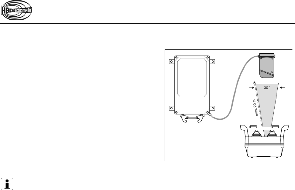
radiomatic® infrakey
The radio s ystem can o nly be ac tivated via a n infrared
link b etween the t ransmitter and t he r eceiver. This
increases the s afety of o peration, i.e. the machine can
not become inadvertently enabled.
radiomatic® infrakey operates either w ith an infrared
module i n the r eceiver housing ( radiomatic® infrakey
internal) or w ith the offset i nfrared antenna fo cus I
(radiomatic® infrakey external).
To activate radiomatic® infrakey, actuate the start button
on the transmitter.
Function of radiomatic® infrakey with focus I
Notes:
•
The range of the infrared beam is max. 20 m (66 ft).
•
The angle of radiation is 30°.
• The front panel of the receiver must be visible (only radiomatic
®
infrakey internal).
Pos: 81 /Technische Dok umentation/Betriebs anleitungen/Send er/Optionen/ Module/-22.1- Meister schalter mit Totmannfunk tion (2014-04-23 13:04:57) @ 5\mod_1274349342269_48.d ocx @ 61199 @ @ 1
Joystick with Deadman Function
In order to issue control commands, the button integrated into the joystick must be pressed before the
joystick is moved. The function then locks and remains effective until the joystick is back in the zero
position. This avoids of potential risks through the unintentional actuation of the joystick.
Pos: 82 /Technische Dok umentation/Betriebs anleitungen/Send er/Optionen/Modul e/-28- radiomatic® report - Benutzerkennung @ 5\mod_1 272630464288_48.doc x @ 60748 @ @ 1
radiomatic® report – User Identification
The "user identification" function with the merlin® TUC enables a simple personalization of the radio system
as well as the storage of all user profiles in the radio system. Safety relevant functions can be unlocked
for authorized pe rsonnel onl y and u nauthorized users c an b e pr otected from potentially dangerous
situations. In addition the radio system can store all operating processes for each individual user as well
as the respective operating time of the radio system. This data can be read from the radio system and
shows how long the radio system was in use and how the individual operators used the various functions
of the radio system.
Pos: 83 /Technische Dok umentation/Betriebs anleitungen/Send er/Optionen/Modul e/-31- Zust i mm-Ta ster @ 7\mod_1331715875728 _48.docx @ 92550 @ @ 1
Enabling Switch
The two-step enabling switch provides enhanced safety during maintenance and service work on or in the
machine as well as for applications with multiple users. In order to transmit control commands to the
machine, the operator has to keep the switch pushed into the first step. Only then are the other operating
elements activated. If the operator releases the button or pushes it into the second step (e.g. as the result
of a cramp), al l machine func tions a re i mmediately s topped. With t his, the ope rator i s protected from
dangerous unintended movements of the machine in case he should lose consciousness or no longer has
control over the transmitter.
If an application is controlled by more than one operator, movement commands can only be performed if
all operators keep the enabling switch pushed into the first step.
Pos: 84 /Technische Dok umentation/Betriebs anleitungen/Al lgemein/----- Seitenumbruch ------ @ 1\mod_1219672326234_0.d ocx @ 29509 @ @ 1

13 / 23
Pos: 85 /Technische Dok umentation/Betriebs anleitungen/Send er/Optionen/Mod ule/-23- Vibrationsa larm @ 5\mod_1270800932014_48. docx @ 59930 @ @ 1
Vibration Alarm
With the vibration alarm, the operator can be informed of an impending need to change the battery and/or
potential dangers on t he machine through the vibration of t he transmitter. This information can be for
example pre-warnings for high wind speeds or threatening excess crane loads.
Pos: 86 /Technische Dok umentation/Betriebs anleitungen/Send er/Optionen/Modul e/-24- Frontplattenbe leuchtung @ 5\mod_127261897 8162_48.docx @ 60640 @ @ 1
Front Panel Lighting
With the front panel lighting potential dangers resulting from incorrect operation, based on poor visibility,
can be prevented. The operator simply switches on multiple LEDs, which are integrated into the rollover
bar, with a switch or button on the transmitter.
Pos: 87 /Technische Dok umentation/Betriebs anleitungen/Send er/Optionen/Modul e/-25- Abschaltung bei un plausiblen Steuerbef ehlen @ 5\mod_1272626650143_ 48.docx @ 60667 @ @ 1
Shut-off on Implausible Control Commands
The automatic shut-off will activate after a sequence of multiple questionable movement commands, for
example if the operator moves the joystick successively in different directions in an irregular manner.
This function protects the operator and the whole work environment from potential dangers as well as the
machine from wear resulting from rapid and erratic movements.
Depending on the ordered version this function can operate in three different ways:
• The complete radio system is shut down.
• Safety-relevant functions are deactivated.
• A previously defined function (e. g. crane horn) is activated.
To deactivate the function, press the start button until the status LED flashes green.
Then the transmitter is ready to operate again.
Pos: 88 /Technische Dok umentation/Betriebs anleitungen/Send er/Optionen/Modul e/-26- Microfahr t @ 5\mod_1272628154655_48.doc x @ 60694 @ @ 1
Micro Drive
With the m icro drive function the speed of the machine is limited to a preselected level. Even at full
movement of the joystick/linear lever, the operator can not exceed this speed limit. In this manner
demanding drive maneuvers can be managed and inexperienced users can be p rotected from potential
dangers that can result from “speeding”.
Pos: 89 /Technische Dok umentation/Betriebs anleitungen/Send er/Optionen/Modul e/-27- Orthogonalfahr t @ 5\mod_1272629557442_48. docx @ 60721 @ @ 1
Orthogonal Drive (Electronic Cross Gate)
With the orthogonal drive function dangerous situations, caused by unintentional diagonal movements are
being prevented. T he o perator w ill hav e t o r eturn t he j oystick bac k to zero position befo re another
directional command can be activated. This function i s s uitable for example fo r s ituations w here t he
operator has to make precision commands in confined areas. Diagonal movements are not possible.
Pos: 90 /Technische Dok umentation/Betriebs anleitungen/Al lgemein/----- Seitenumbruch ------ @ 1\mod_1219672326234_0.d ocx @ 29509 @ @ 1

14 / 23
Pos: 91 /Technische Dok umentation/Betriebs anleitungen/Send er/Optionen/Modul e/-02.1- Frequenzmanage ment_Festfrequen z @ 5\mod_1274424301000_48.doc x @ 61290 @ 2 @ 1
Frequency Management
Fixed Frequency
If t he identification pl ate in th e b attery c ompartment o f t he transmitter s hows a fr equency v alue (e.g.
433,500 MHz), the transmitter operates with a fixed frequency.
Please contact your service department if the frequency has to be changed because the radio channel is
already assigned to another user.
Pos: 93 /Technische Dok umentation/Betriebs anleitungen/Send er/Optionen/Modul e/-02.3- Man. Frequen zweiterschaltung - 1 - @ 2\mod_1226410169843_48. docx @ 36763 @ @ 1
Manual Frequency Switching
If the identification plate in the battery compartment of the transmitter shows the label man, the transmitter
features manual frequency switching.
This function can be used to change the radio channel during radio operation.
Pos: 94 /Technische Dok umentation/Betriebs anleitungen/Send er/Optionen/Modul e/-02.3- Man. Frequen zweiterschaltung - 2 - Start-Tas ter @ 2\mod_122641035020 3_48.docx @ 36785 @ @ 1
Actuate the start button until an acoustic signal sounds. Then release the button.
Pos: 96 /Technische Dok umentation/Betriebs anleitungen/Send er/Optionen/Modul e/-02.3- Man. Frequen zweiterschaltung - 3 - @ 2\mod_1226410472171_48. docx @ 36829 @ @ 1
Please contact your service department if all available frequencies are occupied.
Pos: 97 /Technische Dok umentation/Betriebs anleitungen/Send er/Optionen/Modul e/-02.4- radiomatic AFS @ 2\mod_1226404846046_48.d ocx @ 36720 @ @ 1
radiomatic® AFS
If the identification plate in the battery compartment of the transmitter shows the label AFS, the transmitter
is equipped with radiomatic® AFS (Automatic Frequency Selection).
When activating the transmitter radiomatic® AFS will check if the present radio channel is free. If the radio
channel is occupied, the system automatically finds and saves a free radio channel.
If the radio channel currently i n use is oc cupied by another radio c ontrol s ystem, you must switch th e
transmitter off and on again in order to allow radiomatic® AFS to switch to a free radio channel.
The radiomatic® AFS option also includes the manual frequency switching function.
Note:
If r adiomatic® AFS i s to perform op timally, all the other radio systems in the i mmediate working
environment (e.g. the factory hall or building site) should be switched on before starting to use the
radio s ystem fo r the fi rst ti me. T his allows radiomatic® AFS to detect au tomatically w hich radio
channels are already being used in the working area, and thereby to choose a suitable free channel
for its own use.
In addition, when switching the radio system on for the first time, the user should make sure that
his distance from the radio receiver and from the machine is a realistic reflection of the working
situation.
Pos: 98 /Technische Dok umentation/Betriebs anleitungen/Send er/Optionen/Modul e/-02.5- radiomatic AFM @ 2\mod_12 26405509812_48.d ocx @ 36741 @ @ 1
radiomatic® AFM
If the identification plate in the battery compartment of the transmitter shows the label AFM the transmitter
is equipped with radiomatic® AFM (Automatic Frequency Management).
radiomatic® AFM detects available radio channels constantly. If the radio channel currently in use is
occupied by another radio control system, radiomatic® AFM switches automatically to a free radio channel.
Pos: 100 /Technische Do kumentation/Betri ebsanleitungen/Sen der/Optionen/Modu le/-02.6- DECT @ 8\mod_133362773 4888_48.docx @ 93190 @ @ 1
DECT
DECT tec hnology is an extremely convenient method for un interrupted radio control without frequency
conflicts. The operator always works on a free radio channel and does not need to make manual settings.
Pos: 101 /Technische Do kumentation/Betri ebsanleitungen/Sen der/Optionen/Modu le/-02.7- 2,4 GHz-Technologie @ 8\mod_13 33627927878_48.doc x @ 93218 @ @ 1
2.4 GHz technology
2.4 GHz technology works with automatic frequency coordination and thus ensures interruption-free
working i n a reas w ith many radio users. M anual fr equency c oordination i s no t n ecessary. W ith the
worldwide frequency band, 2.4 GHz technology can be used all over the world.
Pos: 102 /Technische Do kumentation/Betr iebsanleitungen/Al lgemein/----- Seitenumbruch ------ @ 1\mod_1219672326234_ 0.docx @ 29509 @ @ 1
15 / 23
Pos: 103 /Technische Do kumentation/Betri ebsanleitungen/Sen der/Optionen/Modu le/-03.1- Übernahme-Fr eigabe @ 13\mod_14440279609 29_48.docx @ 144744 @ 2 @ 1
Catch-Release
Via the Catch-Release option two or m ore transmitters can control a
machine alternately.
When the receiver is switched on, the machine can initially be controlled
via any associated transmitter. Once the receiver is taken over by one
transmitter, the other transmitters no longer have access.
Take over machine
1. Switch the transmitter on.
2. Enter the "Catch" command on the transmitter and actuate the
start button.
The access rights for the machine remain with that transmitter until the
"Release" command is issued by that transmitter.
Release machine
1. Enter the "Release" command on the transmitter.
2. Switch the transmitter off.
The access rights for the machine are cancelled. Machine control can be taken over by another transmitter.
Operating Example:
Transmitter 1 has taken over the machine. Transmitter 2 is to be given control.
1. Enter the "Release" command on transmitter 1.
2. Switch transmitter 1 off.
3. Switch transmitter 2 on.
4. Enter the "Catch" command on transmitter 2 and actuate the start button.
Transmitter 2 now has sole access to all machine functions.
Pos: 104 /Technische Do kumentation/Betri ebsanleitungen/Sen der/Optionen/Modu le/-03.4- Hinweise Übernah me-Freigabe / - Tandemfahrt @ 13\mod_14416 40528831_48.doc x @ 143614 @ @ 1
Notes:
•
If a r eceiver has already been adopted by a tra
nsmitter can be displayed via a lamp on the
machine.
•
If the op erating v oltage of the r eceiver is disrupted, the receiver has t o b e c atched b y t he
transmitter again.
•
If the transmitter is deactivated without the command "Release" having been issued, the oth
er
transmitters have no access to the receiver. In this case, deactivate all transmitters paired with
the receiver and shortly disconnect the operating voltage from the receiver. This will reset the
system to the starting condition described above.
•
Always
activate the "catch" command after the radio connection has been disrupted in order to
maintain the connection of your radio transmitter to the selected radio receiver(s).
Pos: 105 /Technische Do kumentation/Betri ebsanleitungen/Al lgemein/----- Seitenumbruch ------ @ 1\mod_1219672326234_0. docx @ 29509 @ @ 1
16 / 23
Pos: 106 /Technische Do kumentation/Betri ebsanleitungen/Sen der/Optionen/Modu le/-03.2- Tandemfahrt ne u @ 5\mod_1281505145362_4 8.docx @ 62660 @ 2 @ 1
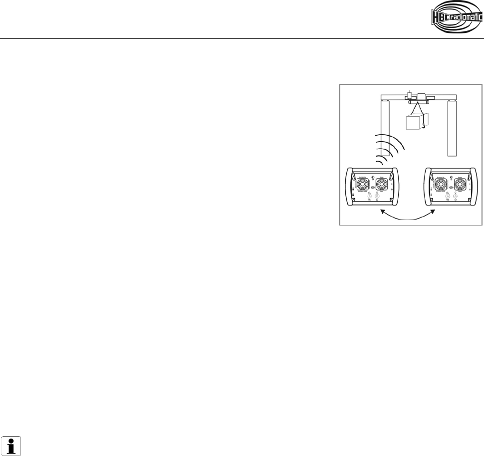
Tandem Operation
Tandem Operation T1
The r adio system c onsists o f 1 t ransmitter a nd 2 receivers fo r 2
machines. The transmitter can control the machines individually or in
parallel.
The machines are selected at the transmitter via a rotary switch:
A only machine A
A+B machine A + machine B
B only machine B
Tandem Operation T2
The radio system consists of 2 transmitters and 2 receivers for 2 machines. Both transmitters are master
transmitters and can control the machines individually or in parallel.
During normal operation transmitter 1 controls machine A and transmitter 2 controls machine B. In order
to be a ble to switch to m achine B or A+B at tr ansmitter 1, for example, the key must be removed from
transmitter 2 and inserted in transmitter 1.
The machines are selected at the transmitter via a rotary switch:
A only machine A
A+B machine A + machine B
B only machine B
Operating Example: Control of machine A + B via transmitter 1.
1. Switch transmitter 1 and 2 off and remove the key from transmitter 2.
2. Insert the key from transmitter 2 in transmitter 1.
Machine selection via transmitter 1 is activated.
3. Turn the rotary switch of transmitter 1 to A+B.
4. Switch transmitter 1 on and actuate the start button.
The radio system now operates in tandem mode.
Warning:
For safety reasons, it is imperatively required that only one key is available for each transmitter.
The spare key must be stored at a superior, authoritative position and only be handed out in clarified
cases.

17 / 23
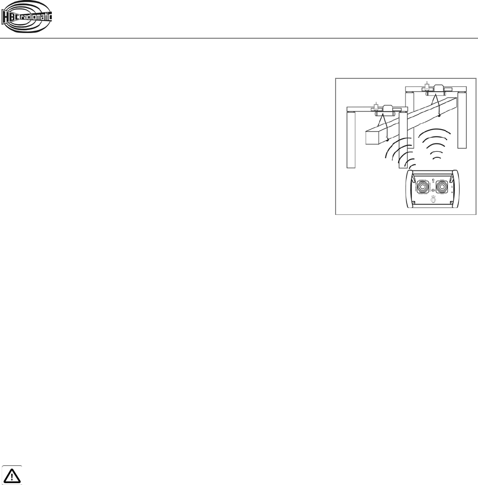
Tandem Operation TM/TS
The radio system consists of 2 transmitters and 2 receivers for 2 machines. One transmitter is a master
transmitter a nd c an c ontrol the m achines individually or i n parallel. The o ther transmitter i s a s lave
transmitter and can only control machine B.
In order to be able to switch to machine B or A+B at the master transmitter, the key must be removed from
the slave transmitter and inserted in the master transmitter.
The machines are selected at the transmitter via a rotary switch:
A only machine A
A+B machine A + machine B
B only machine B
Operating Example: Control of machine A + B via master transmitter.
1. Switch master and slave transmitter off and remove the key from slave transmitter.
2. Insert the key from slave transmitter in master transmitter.
Machine selection via master transmitter is activated.
3. Turn the rotary switch of master transmitter to A+B.
4. Switch master transmitter on and actuate the start button.
The radio system now operates in tandem mode.
Warning:
For safety reasons, it is imperatively required that only one key is available for each transmitter.
The spare key must be stored at a superior, authoritative position and only be handed out in clarified
cases.
Pos: 107 /Technische Do kumentation/Betri ebsanleitungen/Al lgemein/----- Seitenumbruch ------ @ 1\mod_1219672326234_0. docx @ 29509 @ @ 1

18 / 23
Pos: 108 /Technische Do kumentation/Betri ebsanleitungen/Sen der/Optionen/Modu le/-03.3- Übernahme-Fr eigabe-Tandemfahrt @ 13\mod_14440 31086609_48.docx @ 144894 @ 2 @ 1
Catch-Release-Tandem Operation
With th e C atch-Release-Tandem O peration two or m ore tr ansmitters c an c ontrol several m achines
alternately.
Each machine is equipped with a receiver that can receive and monitor all transmitter frequencies.
After activating the receivers all transmitters have equal access to the radio control system.
Take over machine
1. Switch the transmitter on.
2. Turn rotary switch on the transmitter to the respective position.
3. Enter the "Catch" command on the transmitter and actuate the start button.
The transmitter with control over the machine(s) retains the access to the receiver until the operator has
issued the "Release" command.
Release machine
1. Enter the "Release" command on the transmitter.
2. Switch the transmitter off.
The access rights for the machine(s) a re c ancelled. Machine control c an be ta ken o ver b y another
transmitter.
Operating Example:
Transmitter 1 has taken over machine A. Transmitter 2 is to be given control over machine A+B.
1. Enter the "Release" command on transmitter 1.
2. Switch transmitter 1 off.
3. Switch transmitter 2 on.
4. Turn rotary switch on transmitter 2 to A+B.
5. Enter the "Catch" command on transmitter 2 and actuate the start button.
Transmitter 2 now has sole access to all machine functions.
Pos: 109 /Technische Do kumentation/Betri ebsanleitungen/Sen der/Optionen/Modu le/-03.4- Hinweise Übernah me-Freigabe / - Tandemfahrt @ 13\mod_14416 40528831_48.doc x @ 143614 @ @ 1
Notes:
•
If a receiver has already been adopted by a transmitter can be displayed via a lamp on the
machine.
•
If the operating voltage of the receiver i s di srupted, the r eceiver has to be catched
by t he
transmitter again.
•
If the transmitter is deactivated without the command "Release" having been issued, the other
transmitters have no access to the receiver. In this case, deactivate all transmitters paired with
the receiver and shortly disconnect
the operating voltage from the receiver. This will reset the
system to the starting condition described above.
•
Always activate the "catch" command after the radio connection has been disrupted in order to
maintain the connection of your radio transmitter to the selected radio receiver(s).
Pos: 110 /Technische Do kumentation/Betri ebsanleitungen/Al lgemein/----- Seitenumbruch ------ @ 1\mod_1219672326234_0. docx @ 29509 @ @ 1
19 / 23
Pos: 111 /Technische Do kumentation/Betri ebsanleitungen/Sen der/Optionen/Modu le/-05- Kabelsteuerung @ 14\mod_1474272619204_48. docx @ 177745 @ 2 @ 1
Cable Control
With a cable you can generate a direct data connection between
the transmitter and receiver. The radio transmission is disabled.
At the same time, the power supply of the transmitter is provided
through the cable, as well.
Connecting the cable
1. Switch the transmitter off.
2. Remove the screw lock on the transmitter and receiver.
3. Connect the transmitter and the receiver with the cable.
Ensure that the connector is locked.
4. Switch the transmitter on.
Notes:
•
If y ou c onnect t he c able w hile w orking w ith the s ystem, t he
transmitter w ill sw itch o ff
automatically.
Activate the transmitter as describe in the chapter “Operation” to switch to cable
operation.
•
When the s ystem i s i n c able m ode t he transmitter w ill receive t he s upply v oltage from the
receiver, i.e. the transmitter can be used without the battery.
•
If y ou
disconnect t he cable f rom th e t ransmitter and receiver, th e s ystem w ill s witch o ff
automatically.
Activate the transmitter as describe in the chapter “Operation” to switch to radio
operation.
Pos: 112 /Technische Do kumentation/Betr iebsanleitungen/Sen der/Optionen/ Module/-15- HF-Verst ärker @ 2\mod_123745010787 5_48.docx @ 42530 @ 2 @ 1
RF-amplifier
If the transmitter is equipped with an RF-amplifier, please refer to the transmitter wiring diagram. There
you can also find the instructions on how to activate the RF-amplifier.
Pos: 113 /Technische Do kumentation/Betri ebsanleitungen/Sen der/Optionen/Modu le/-10- Taster "Ein" al s Umschalttaster @ 2\mod_12263 94707421_48.doc x @ 36592 @ 2 @ 1
Utilization of Button as Shift Key
The RPM+ and RPM– buttons have a dual function.
If the button is kept pressed and the RPM+ resp. RPM– button is also activated, the Motor Start resp.
Motor Stop command will be output.
Pos: 114 /Technische Do kumentation/Betri ebsanleitungen/Sen der/Optionen/Mo dule/-16- Vorwahl von Katz e oder Hubwerk @ 2\mod_12266714 85906_48.docx @ 37242 @ 2 @ 1
Pre-selection of Trolley or Hoist
The operator i s able to s elect th e t rolley o r ho ist th at h e w ishes to c ontrol. I t i s also pos sible to
simultaneously control both trolleys/hoists, for example in order to transport particularly long or wide loads.
Pos: 115 /Technische Do kumentation/Betr iebsanleitungen/Sen der/Optionen/ Module/-14- Rückmeldun g über LED @ 2\mod_1226666981593_48. docx @ 37200 @ 2 @ 1
Feedback by LED
Using this function, system or machine data can be displayed on the transmitter by
LEDs.
Pos: 116 /Technische Do kumentation/Betr iebsanleitungen/Sen der/Optionen/Modu le/-33- Bankumschaltung @ 7\mod_1331716870074_48 .docx @ 92609 @ 2 @ 1
Bank Switch
By switching operating levels via rotary switch or push button, the operator can choose between different
operating levels. The number of available commands can be multiplied, even for small transmitters.
Pos: 117 /Technische Do kumentation/Betri ebsanleitungen/Al lgemein/----- Seitenumbruch ------ @ 1\mod_1219672326234_0. docx @ 29509 @ @ 1
20 / 23
Pos: 118 /Technische Do kumentation/Betr iebsanleitungen/Sen der/Optionen/ Module/-12- Drehschalt er Geschwindigkeit svorwahl @ 2\mod_12263970 16671_48.docx @ 36656 @ 2 @ 1
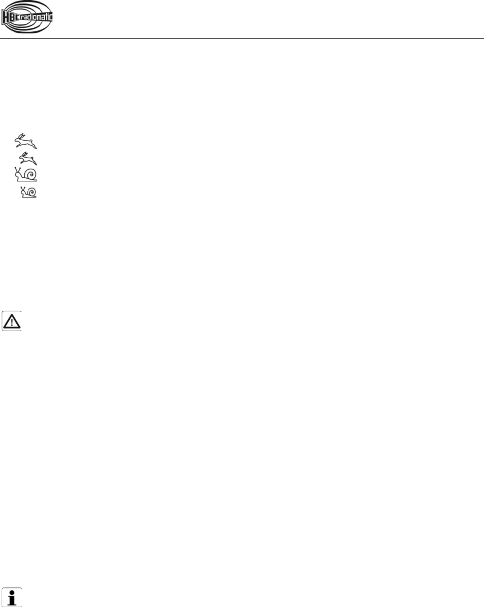
Rotary Switch for Pre-selected Speed
Using the rotary switch it is possible to choose between four maximum machine speeds, which are set in
accordance with the customer’s requirements.
The symbols for the speed adaptation have the following meanings:
= maximum speed 100 %
= maximum speed, limited to 75 %
= maximum speed, limited to 50 %
= maximum speed, limited to 25 %
Pos: 119 /Technische Do kumentation/Betri ebsanleitungen/Sen der/Optionen/Modu le/-20- Senderhochtas tung (allgemein) @ 2\mod_1226 398809375_48.doc x @ 36698 @ 2 @ 1
Transmitter Key Up
With the transmitter key up function, radio commands are only transmitted at the touch of a key and the
transmitter will automatically be switched off af ter 7 s econds of non-use. For ex ample, self-monitoring
gates can thus be opened or closed by several operators.
During longer breaks the transmitter must be switched off by pressing the STOP switch.
The "transmitter key up" function also saves battery power.
Caution:
The transmitter key up function does not relieve the operator of hi s r esponsibility to turn off the
transmitter with the STOP switch when not in use.
Pos: 120 /Technische Do kumentation/Betri ebsanleitungen/Sen der/Optionen/Modu le/-30- radiomatic ® CPS @ 14\mod_1484574810375_4 8.docx @ 181355 @ 2 @ 1
radiomatic® CPS
radiomatic® CPS (= Continuous Power Supply) enables a battery exchange without interrupting power. For
this, the transmitter is equipped with two battery compartments or an additional, integrated battery. By
means of two LEDs, the operator can at all times see which battery is in use or if a battery needs to be
charged. If a battery has to be charged, the process automatically switches to the battery in the second
compartment or the integrated battery. The radio system remains active. Thus the feature is perfect for
applications where long and continuous crane or machine operations are required.
Pos: 121 /Technische Do kumentation/Betri ebsanleitungen/Sen der/Optionen/Modu le/-32- radiomatic ® iBAR @ 7\mod_1331716787394_48 .docx @ 92580 @ 2 @ 1
radiomatic® iBAR
radiomatic® iBAR stands for a newly developed, intelligent over-roll bar. With this, the function range of
the control can be considerably expanded.
radiomatic® iBAR can be configured with diverse additional operating elements, e.g. push buttons.
In addition, LCDs for data indication can be integrated.
Pos: 122 /Technische Do kumentation/Betri ebsanleitungen/Sen der/Optionen/Modu le/-13- Windfrei stellung @ 2\mod_122667077640 6_48.docx @ 37221 @ 2 @ 1
Slewing Gear Release
Note:
Whenever th e c ommand "slewing g ear release" i s ac tuated by m eans of t he radio c ontrol, i t i s
important that the respective check be made.
Due to the above, a clearly visible indicator lamp should be installed on the machine.
Pos: 123 /Technische Do kumentation/Betri ebsanleitungen/Al lgemein/----- Seitenumbruch ------ @ 1\mod_1219672326234_0. docx @ 29509 @ @ 1
21 / 23
Pos: 124 /Technische Do kumentation/Betri ebsanleitungen/ Technische Daten/_Ü1 - TD @ 1\mod_12215 52834937_48.docx @ 3502 6 @ 1 @ 1
Technical Data
Pos: 125 /Technische Do kumentation/Betri ebsanleitungen/ Technische Daten/Sender /TD_VS_Sender @ 10\mod_137 8361521654_0.doc x @ 112253 @ @ 1
Max. number of control commands -
Unique system addresses Over 1.000.000 combinations
Supply voltage 6 V
Safety function E-STOP:
Performance Level d, category 3 according to EN
ISO 13849-1:2015
Frequency ranges2 405 – 475 MHz1, 865 – 870 MHz,
902 – 928 MHz, 1210 – 1258 MHz1
2.4 GHz: 2402 – 2480 MHz
DECT: 1790 – 1930 MHz
Channel spacing 12.5 / 20 / 25 / 50 / 250 kHz
2.4 GHz: 1 MHz
DECT: 1.728 MHz
Antenna Internal
Option: external
Battery type BA213020 (NiMH)
Battery capacity 2 x 2100 mAh
Continuous operating time Approx. 12 h
Operating temperature range -20 °C … +70 °C (-4 °F ... +158 °F)
Housing material Glass-fiber reinforced plastic / PA6 GF30
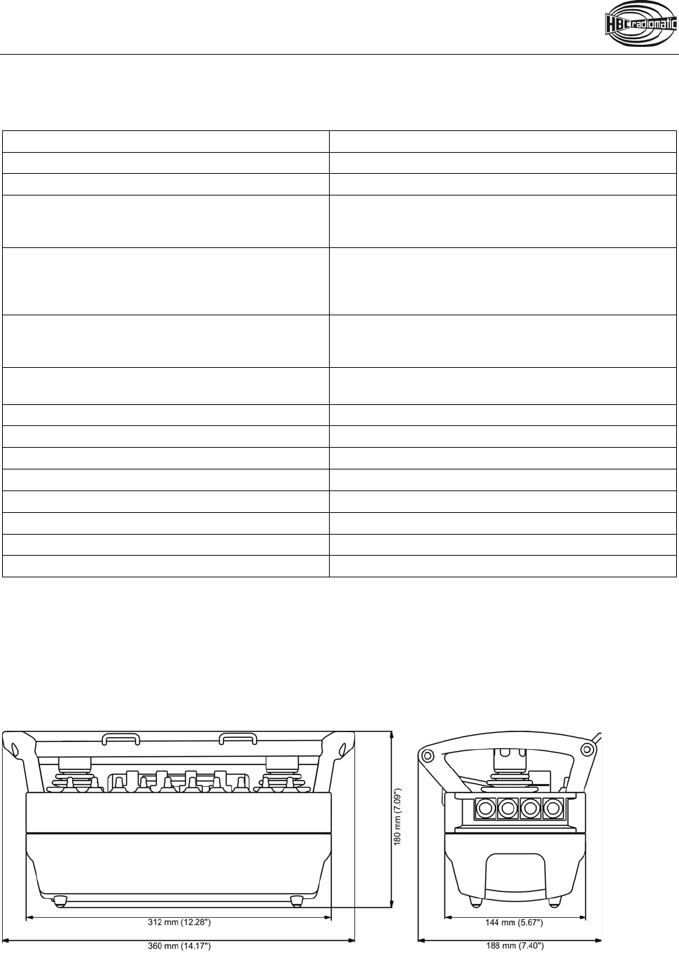
Dimensions 360 x 188 x 180 mm (14.17 x 7.4 x 7.09 inches)
Weight (incl. battery) Approx. 3.0 kg (6.61 lbs.)
Protection class IP65
1 Not all frequency ranges available.
2 Some versions are not intended for use in the USA. Please contact Sales at HBC-radiomatic GmbH to find out which
version is available for the USA.
Pos: 127 /Technische Do kumentation/Betri ebsanleitungen/Ab messungen/_Ü1 - Abmessunge n @ 1\mod_1221645928875_4 8.docx @ 35060 @ 1 @ 1
Dimensions
Pos: 128 /Technische Do kumentation/Betri ebsanleitungen/Ab messungen/Sender/ Abmessungen_Sender_VS_ neu @ 11\mod_140325037 3951_0.docx @ 123473 @ @ 1
Pos: 129 /Technische Do kumentation/Betri ebsanleitungen/Al lgemein/----- Seitenumbruch ------ @ 1\mod_1219672326234_0. docx @ 29509 @ @ 1

22 / 23
Pos: 130 /Technische Do kumentation/Betri ebsanleitungen/Sen der/Problembehandl ung - Sender @ 1\mod_1220958 012656_48.docx @ 30229 @ 1 @ 1
Troubleshooting
Note:
Please check the functions using the cabin or cable controls first!
Problem Possible Cause Remedy
Transmitter does not react
when switched on.
− No power. − Check battery contacts for
damage or contamination.
− Insert a fully charged battery
into the battery compartment.
−
Recharge battery.
Low-power indication after
minimal operating time.
− Battery contacts are
contaminated or damaged.
− Battery not charged.
− Battery defective.
− Check battery contacts for
damage or contamination.
− Recharge battery.
− Ensure that recharging
process runs correctly.
− Check transmitter functions
using a fully charged or
replacement battery.
The display in the transmitter
flashes green but it is not
possible to effect control
commands.
− Receiver has no voltage.
− No radio communication.
− "Crane On" command has not
been given.
− Check the connecting cable
to the receiver.
− Check the functions via the
LEDs in the radio status
panel of the receiver.
Some commands are not
carried out.
− Receiver defective.
− Interruption in the connecting
cable to the machine.
− Check if all connecting cables
and cable junctions are tight.
If none of the measures mentioned resolve t he p roblem, then pl ease c ontact y our s ervice tec hnician,
distributor or HBC-radiomatic.
Pos: 131 /Technische Do kumentation/Betri ebsanleitungen/Al lgemein/----- Seitenumbruch ------ @ 1\mod_1219672326234_0. docx @ 29509 @ @ 1

23 / 23
Pos: 132 /Technische Do kumentation/Betri ebsanleitungen/Sen der/Wartung - S ender @ 1\mod_1219742392562_48. docx @ 29964 @ 1 @ 1
Maintenance
The radio control system is virtually maintenance-free. Please observe the following points:
• Check the STOP switch functionality at regular intervals. Dirt deposits on the switch can hinder the
mechanism and impair the function.
• Check the rubber bellows or rubber seals of the operating elements at regular intervals f or l eak-
tightness. Replace immediately if cracks appear since the penetration of dirt and humidity may damage
the function of the operating elements.
• Never use a high-pressure cleaner or sharp or pointed objects to clean the transmitter.
• Charge and discharge transmitter batteries regularly.
Pos: 133 /Technische Do kumentation/Betri ebsanleitungen/Al lgemein/Im Falle eines Def ekts @ 1\mod_121973835575 0_48.docx @ 29926 @ @ 1
In the Event of a Fault
Warning:
Never operate a machine with a faulty or defective radio control system!
• Never try to repair the electronics of the radio control system! Opening the transmitter or receiver
housing terminates the manufacturer warranty.
− Send any defective or faulty equipment to your local distributor or to the manufacturer. They are
experts and have the necessary know-how and OEM spare parts.
− Always s end i n th e c omplete radio system ( transmitter, r eceiver, ba tteries, ba ttery c harger,
connection cables, and other equipment) and attach a detailed fault description.
− Do not forget to enclose your address and telephone number so that we can get in touch with you
quickly if necessary.
• To avoid damage during transport, use the original packing supplied with the radio control system;
otherwise pack securely. Send the consignment to your distributor or to the following address:
HBC-radiomatic, Inc.
1017 Petersburg Road
Hebron, KY 41048, USA
Telephone: +1 800 410-4562
Fax: +1 866 266-7227
• Should you decide to personally return a defective radio system to your distributor or
HBC-radiomatic, Inc., then please make an appointment first.
For an overview of our worldwide service and sales contacts, please visit our website
www.hbc-radiomatic.com under "Contact".
=== Ende der Liste für Textmarke Inhalt2 ===
Pos: 135 /TecPos: 138 /Techni sche Dokumentati on/Betriebsanleit ungen/Konformitae tserklaerung/Vari ablensteuerung/KE_S ender_VS @ 12\mod_143531 5744822_48.doc x @ 139484 @ @ 1
=== Ende der Liste für Textmarke Inhalt3 ===