HEI Advanced Medical Division L100 Link-IT Wireless Connectivity Device User Manual 01090 00059A
HEI, Inc. Advanced Medical Division Link-IT Wireless Connectivity Device 01090 00059A
Users Manual

Link-iT™ System
USER’S MANUAL
Revision A
12/10/2003
Part Number 01090-00059
For Orders and Support:
1-800-866-3716
www.heii.com
This device complies with Part 15 of the FCC Rules. Operation is
subject to the following two conditions: (1) this device may not
cause harmful interference, and (2) this device must accept any
interference received, including interference that may cause
undesired operation.

Link-iT™ System USER’S MANUAL Page 2 of 20
01090-00059, Revision A
TABLE OF CONTENTS
1 Overview ................................................................................................... 3
2 Safety Instructions.................................................................................... 3
2.1 Symbols ............................................................................................ 3
2.2 Precautions........................................................................................ 3
2.3 Product Labeling & Identification .................................................... 5
3 System Description................................................................................... 6
3.1 Product Configurations And Descriptions ........................................ 7
3.2 Features Of The Link-iT Module...................................................... 8
3.2.1 Communication Ports................................................................... 8
3.2.2 Link-iT™ Module LED Indicators............................................... 9
4 Installation .............................................................................................. 10
4.1 Connecting With RS-232................................................................ 10
4.2 Connecting With USB .................................................................... 10
4.3 Connecting With A Wired Network ............................................... 11
4.4 Connecting With A Wireless Network ........................................... 11
4.5 Connecting With IrDA.................................................................... 11
4.6 Connecting To Power ..................................................................... 12
4.7 Use Of Link-iT Mounting Bracket..................................................14
5 Maintenance and Support ..................................................................... 15
5.1 Initial System Configuration........................................................... 15
5.2 Software Updates............................................................................ 15
5.3 Cleaning.......................................................................................... 15
5.4 Troubleshooting.............................................................................. 16
6 Specifications .......................................................................................... 17

Link-iT™ System USER’S MANUAL Page 3 of 20
01090-00059, Revision A
1 OVERVIEW
This User’s Manual provides guidance on use and routine
maintenance of the Link-iT™ System. End-Users should read and
understand this manual completely before using any components
of the Link-iT™ System. This manual does not cover
configuration, installation of software, repair, or use of the Link-
iT™ modules in a system application. For installation and
compatibility issues, please contact your site administrator.
Audience: The primary audience for the Link-iT™ System User’s
Manual is the clinical care provider. A secondary audience
includes technical service and management personnel.
2 SAFETY INSTRUCTIONS
2.1 SYMBOLS
Caution, refer to the User’s Manual
Caution, Dangerous voltage
2.2 PRECAUTIONS
If any electrical component is suspect of or found to be defective
or inoperable, discontinue use of the Link-iT™ System.
This equipment has been tested and found to comply with the
limits for a Class B digital device, pursuant to Part 15 of the FCC
Rules. These limits are designed to provide reasonable protection
against harmful interference in a residential installation. This

Link-iT™ System USER’S MANUAL Page 4 of 20
01090-00059, Revision A
equipment generates, uses and can radiate radio frequency energy
and, if not installed and used in accordance with the instructions,
may cause harmful interference to radio communications.
However, there is no guarantee that interference will not occur in a
particular installation. If this equipment does cause harmful
interference to radio or television reception, which can be
determined by turning the equipment off and on, the user is
encouraged to try to correct the interference by one or more of the
following measures:
• Reorient or relocate the Link-iT™ System components.
• Increase the separation between the equipment and Link-
iT™ System components.
• Connect the equipment into an outlet on a circuit different
from that to which the Link-iT™ System is connected.
• Consult the dealer or an experienced technician for help.
Changes or modifications not expressly approved by the party
responsible for compliance could void the user’s authority to
operate the equipment.
Link-iT™ System USER’S MANUAL Page 5 of 20
01090-00059, Revision A
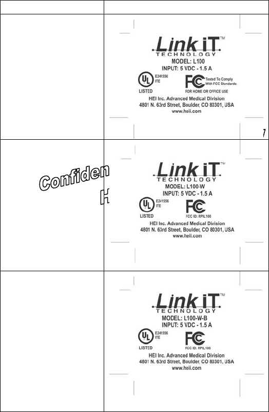
2.3 PRODUCT LABELING & IDENTIFICATION
Product Model Device and Agency Labels
L100
L100-W
L100-W-B

Link-iT™ System USER’S MANUAL Page 6 of 20
01090-00059, Revision A
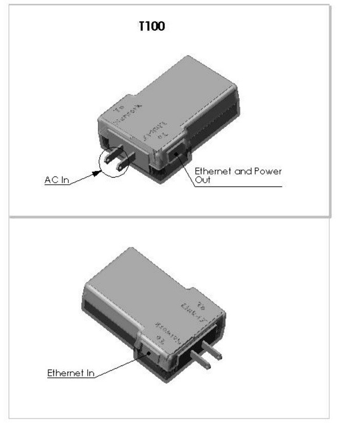
T100
3 SYSTEM DESCRIPTION
The Link-iT™ System is a compact intelligent system intended to
bring processing power and interface capability to a variety of
needs in the medical device arena, particularly in the area of
connecting medical devices and information systems. The system
includes Link-iT™ modules and power supplies. The modules
connect to standard interfaces, including RS-232, IrDA, USB,
Ethernet (10BaseT and 100BaseT), and 802.11b (WiFi) wireless
networking. The Link-iT™ power supply provides direct power
and battery charging capability.
The following items are external components supported by the
Link-iT™ System:
• Medical devices and their specific serial protocols
• Information systems and their specific interface
requirements (e.g. XML or HL7)

Link-iT™ System USER’S MANUAL Page 7 of 20
01090-00059, Revision A
Specific aspects of the interface are dictated by the external device
and may require customization. Before connecting to any device,
consult the operator/user’s manual provided by the device
manufacturer. Contact your site administrator with questions
regarding your system environment.
3.1 PRODUCT CONFIGURATIONS AND DESCRIPTIONS
Product
Configuration Description
L100 Link-iT™ module
T100 Link-iT™ power supply*
L100-T Link-iT™ module and Link-iT™ power supply
L100-W-T Link-iT™ module with WiFi and Link-iT™ power
supply
L100-W-B-T
Link-iT™ module with WiFi, built-in battery pack and
Link-iT™ power supply
*Includes 1 standard RJ-45 cable (6 ft)
Link-iT™ System USER’S MANUAL Page 8 of 20
01090-00059, Revision A
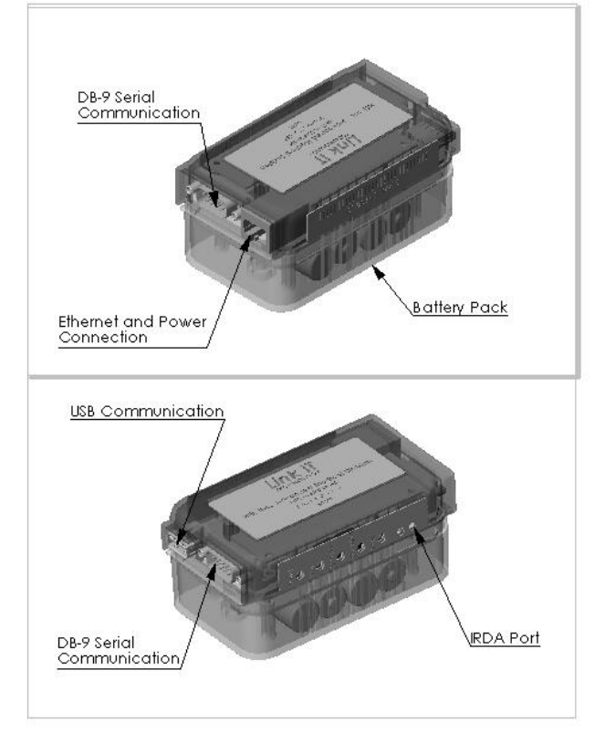
3.2 FEATURES OF THE LINK-IT MODULE
3.2.1 Communication Ports
Link-iT™ System USER’S MANUAL Page 9 of 20
01090-00059, Revision A
Interfaces supported by the Link-iT™ module include two DB-9
connectors standard for serial interfaces, USB that conforms to the
USB 2.0 specification, an IrDA port for infrared communication,
and a RJ-45 connector standard for a wired network interface. The
RJ-45 connector also supplies DC power to the Link-iT™ module.
A single RJ-45 cable is supplied with the Link-iT™ power supply.
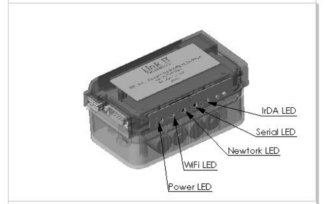
3.2.2 Link-iT™ Module LED Indicators
LEDs on the Link-iT™ module indicate function or activity for
specific aspects of the system.
Power LED - illuminates when the Link-iT™ module has DC
power supplied or flashes/blinks when the Link-iT™ module has
battery power supplied.
WiFi LED – illuminates when the Link-iT™ module has active
wireless communication.

Link-iT™ System USER’S MANUAL Page 10 of 20
01090-00059, Revision A
Network LED – illuminates when the Link-iT™ module has
active network communication.
Serial LED – illuminates when there is active serial
communication or USB communication between the Link-iT™
module and an external device/component.
IrDA LED – illuminates when there is active infrared
communication between the Link-iT™ module and an external
system.
4 INSTALLATION
The Link-iT™ module is configurable with various interfaces
based on the product model type.
NOTE: Interface connections should be made prior to powering on
the Link-iT™ module.
4.1 CONNECTING WITH RS-232
To interface via RS-232, use a serial cable to connect either DB-9
Serial Communication port of the Link-iT™ module to the serial
connector on the external device (e.g. medical instrumentation).
When the Link-iT™ module is powered and has active serial
communication, the Serial LED will illuminate. Custom cabling
may be required for external device connectivity, consult your site
administrator.
4.2 CONNECTING WITH USB
A USB port is available to support additional device interfaces or
to support enhanced system capability. To interface via USB,
connect the USB Communication port of the Link-iT™ module to

Link-iT™ System USER’S MANUAL Page 11 of 20
01090-00059, Revision A
the external device (e.g. external hard drive, printer). When the
Link-iT™ module is powered and has active USB communication,
the Serial LED will illuminate.
4.3 CONNECTING WITH A WIRED NETWORK
A typical interface via Ethernet will use a standard RJ-45 cable to
connect the Ethernet and Power Connection of the Link-iT™
module to the “To Link-iT™” port of the Link-iT™ power supply
(T100). A second RJ-45 cable should connect the “To Network”
port of the Link-iT™ power supply (T100) to the hospital network
jack or hub. The Network LED on the Link-iT™ module will
illuminate when powered and there is active network
communication.
4.4 CONNECTING WITH A WIRELESS NETWORK
Wireless communication is available for Link-iT™ modules with
“W” in the model number. When a Link-iT™ module configured
for 802.11B connectivity has active wireless communication, the
WiFi LED will illuminate.
At this time, simultaneous operation of Ethernet and 802.11B on a
single Link-iT™ module is not supported.
4.5 CONNECTING WITH IRDA
An IrDA (infrared) interface is provided with the Link-iT™
module for integration with a PDA or similar systems. The IrDA
LED will illuminate when there is infrared communication
between a Link-iT™ module and an external infrared system.
Link-iT™ System USER’S MANUAL Page 12 of 20
01090-00059, Revision A
4.6 CONNECTING TO POWER

Link-iT™ System USER’S MANUAL Page 13 of 20
01090-00059, Revision A
To power a Link-iT™ module and/or charge a battery pack:
1) Connect the Ethernet and Power Connection of the Link-
iT™ module to the “To Link-iT™” port of the Link-iT™
power supply (T100) using a standard RJ-45 cable.
2) Plug the T100 directly into a power outlet.
3) Check to see that the Power LED on the Link-iT™ module
illuminates indicating DC Power is applied.
If the Link-iT™ module has a battery pack that is charged, the
main power supply may be disconnected and the Link-iT™ module
used in an ambulatory function for up to 4 hours. The Power LED
on the Link-iT™ module will flash as an indication of battery
power.
The absence of an illuminated Power LED indicates there is no
power to the Link-iT™ module.
Link-iT™ System USER’S MANUAL Page 14 of 20
01090-00059, Revision A
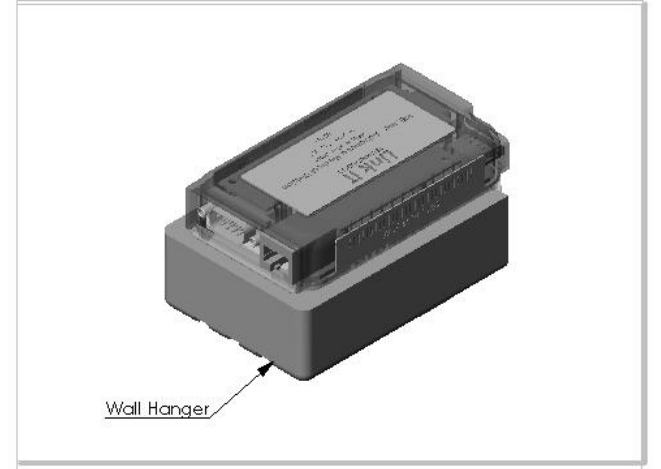
4.7 USE OF LINK-IT MOUNTING BRACKET
The Link-iT™ module can be mounted to various surfaces using a
Link-iT™ mounting bracket. Slide the Link-iT™ module onto the
guides of the bracket.
Note: Brackets are available in various configurations for Link-
iT™ modules, both with battery pack and without battery pack.
Contact your site administrator before attaching mounting brackets
to fixtures or equipment.

Link-iT™ System USER’S MANUAL Page 15 of 20
01090-00059, Revision A
5 MAINTENANCE AND SUPPORT
5.1 INITIAL SYSTEM CONFIGURATION
The Link-iT™ System should be configured only by trained
technical personnel. Contact your site administrator if this is
necessary.
5.2 SOFTWARE UPDATES
Software for the Link-iT™ module should be updated only by
trained technical personnel. Contact your site administrator if this
is necessary.
5.3 CLEANING
CAUTION: Disconnect and unplug the Link-iT™ System
components prior to cleaning.
CAUTION: Do not immerse the Link-iT™ System components in
water or other fluids.
CAUTION: Do not use harsh chemicals or apply cleaning agents
directly on the Link-iT™ System components.
The Link-iT™ System components should be cleaned by using a
cloth dampened with rubbing alcohol or all purpose cleaner and
wiping the exterior surfaces. Be careful not to saturate the Link-
iT™ System components, as excessive liquid will damage the
electronics.

Link-iT™ System USER’S MANUAL Page 16 of 20
01090-00059, Revision A
5.4 TROUBLESHOOTING
Symptom Problem Action
No Power LED No power to Link-iT™
module
Check RJ-45 cable connection.
Check T100 is plugged in.
Check for charged batteries.
Contact site administrator.
No Serial LED
No serial
communication
No USB
Communication
Check serial cable connection.
Check USB connection.
Contact site administrator.
No WiFi LED No wireless
communication
Check model of Link-iT™
module to verify wireless
capability.
Contact site administrator.
No Network
LED No Network
communication
Check RJ-45 cable
connections.
Contact site administrator.
No IrDA LED No infrared
communication Contact site administrator.

Link-iT™ System USER’S MANUAL Page 17 of 20
01090-00059, Revision A
6 SPECIFICATIONS
Dimensions
Link-iT™ module without battery pack:
Width 60 mm (max)
Depth 105 mm (max)
Height 29 mm (max)
Link-iT™ module with battery pack: Width 60 mm (max)
Depth 105 mm (max)
Height 47.5 mm (max)
Wall Transformer (T100): Width 60 mm (max)
Depth 105 mm (max)
Height 30 mm (max)
Operational
Temperature: +0°C to +40°C
Humidity: 5% to 95% relative humidity
non-condensing
Storage Conditions
Temperature: -20°C to +45°C
Humidity: 5% to 95% relative humidity
non-condensing

Link-iT™ System USER’S MANUAL Page 18 of 20
01090-00059, Revision A
NOTES:

Link-iT™ System USER’S MANUAL Page 19 of 20
01090-00059, Revision A
NOTES:

Link-iT™ System USER’S MANUAL Page 20 of 20
01090-00059, Revision A