HELLA and KGaA BCM2 Body computer module 2 User Manual Manual
Hella KGaA Hueck & Co. Body computer module 2 Manual
UserManual.wiki
>
HELLA and KGaA
>
BCM2 User Manual
Manual
Navigation menu
Upload a User Manual
Namespaces
Wiki Guide
HTML
PDF
Info
Views
User Manual
Discussion / Help
Navigation
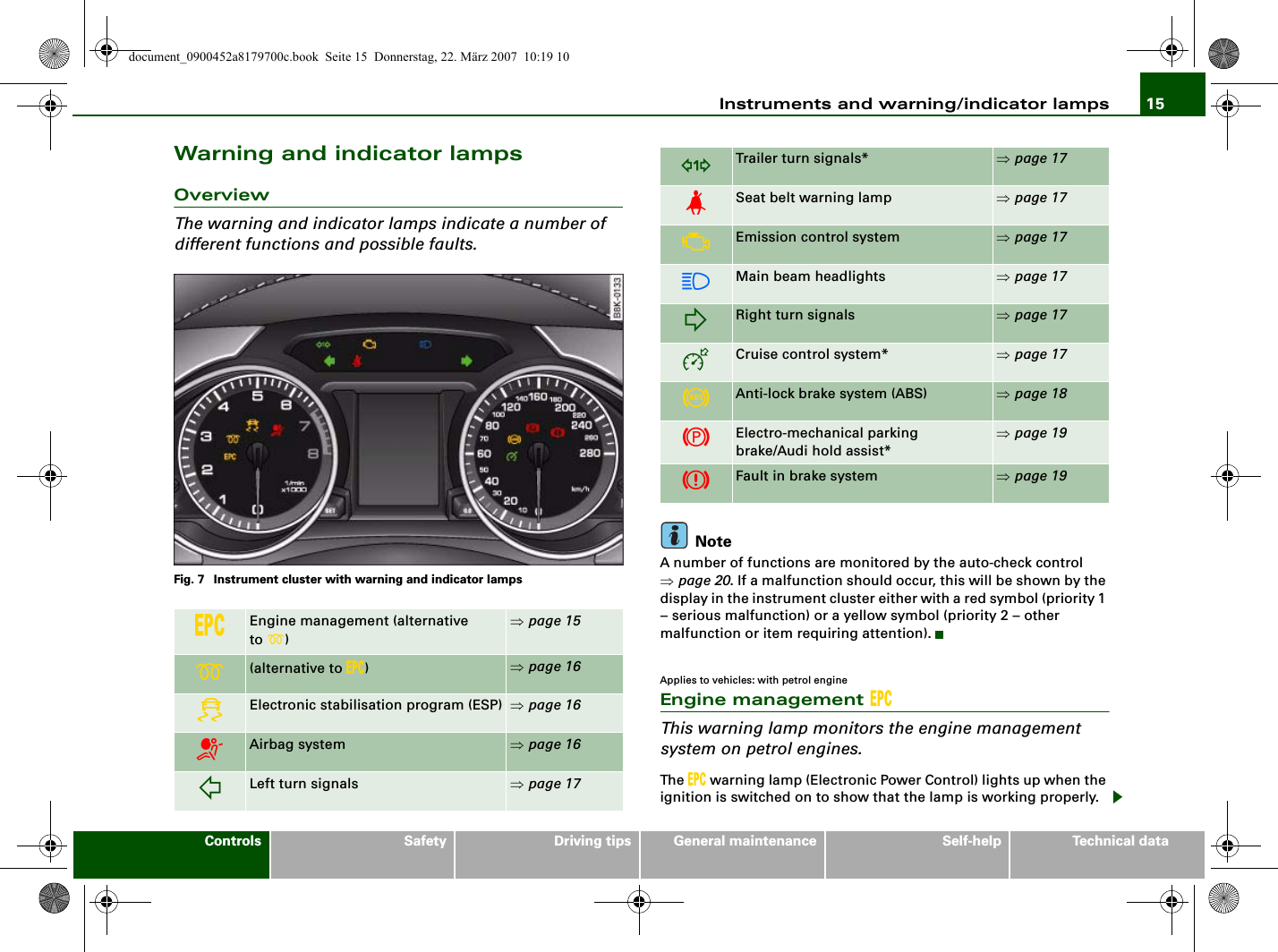
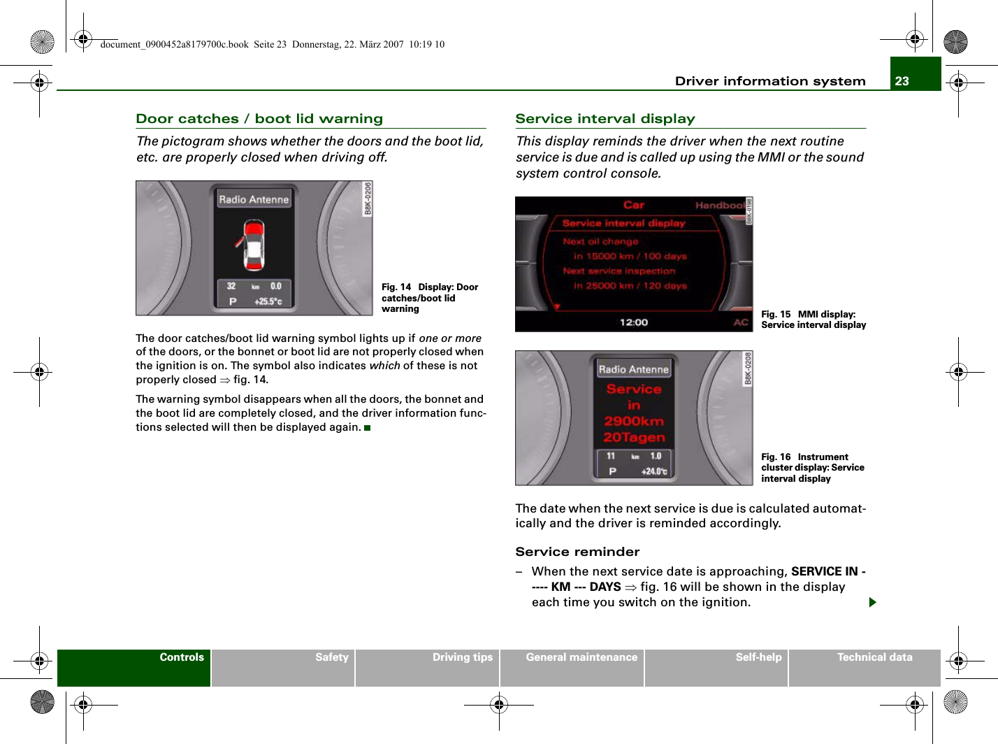

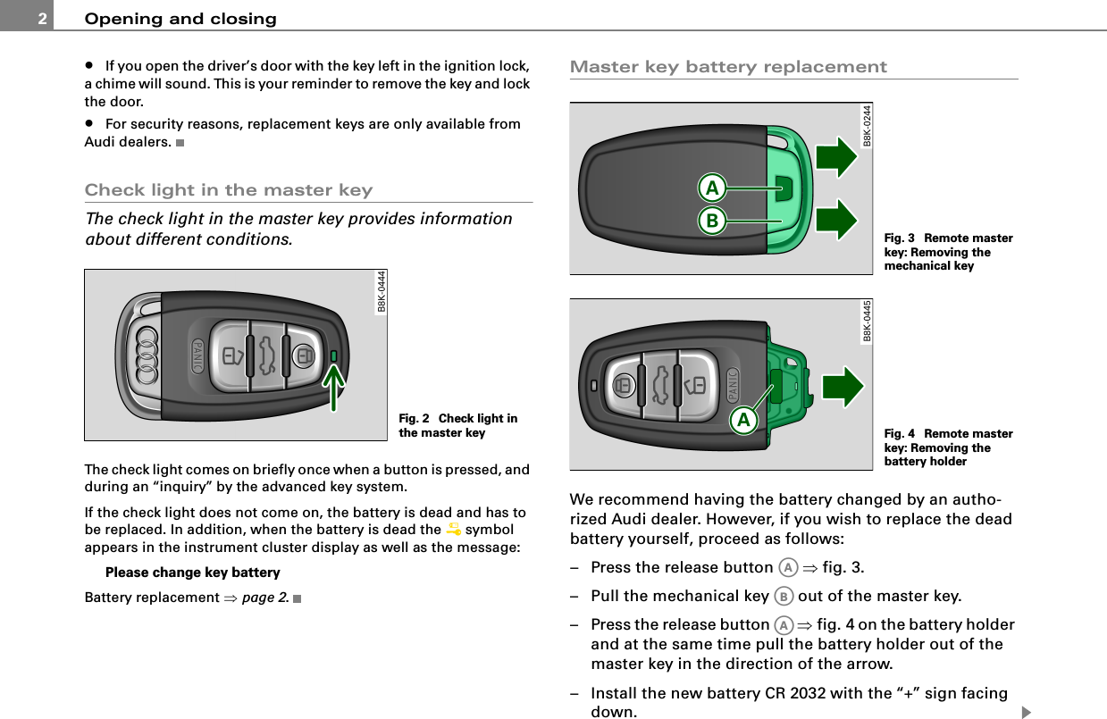
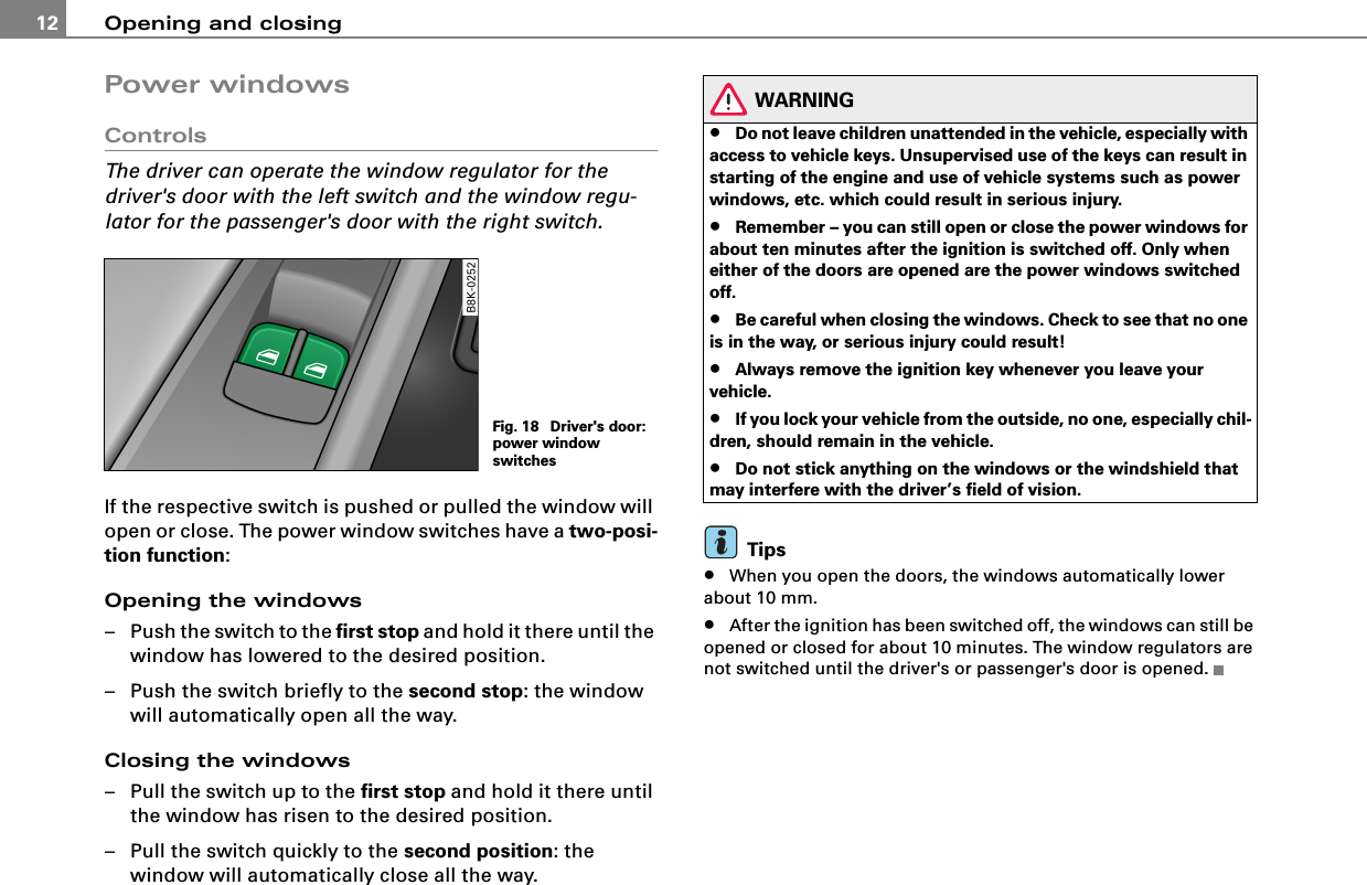
![Opening and closing 3– Push the battery holder carefully into the master key.– Install the mechanical key.For the sake of the environmentDispose of dead batteries properly so as not to pollute the environ-ment.TipsThe replacement battery must be the same specification as the original.Removing the mechanical key– Press the release button ⇒fig. 5.– Pull the mechanical key out of the master key.Using the mechanical key, you can•Lock and unlock* the storage compartment on the passenger's side [Cross reference error: reference link ID='Handschuhfach' not found].•Lock and unlock the lockable rear seat [Cross reference error: reference link ID='Rueckenlehne-abschliessen' not found].•Lock and unlock the vehicle manually ⇒page 9 if this should not be possible with the master key.Emergency unlocking of the ignition keyIn the event of malfunctions in the electrical system, it may happen that you cannot remove the ignition key.If you are unable to remove the ignition key, for example because the vehicle battery is discharged, proceed as follows:– Press the release button ⇒fig. 6 for example with a ball point pen and pull the mechanical key out of the master key.– Lock the vehicle using the mechanical key ⇒page 9.– Have the electrical system inspected by an authorized Audi dealership.Fig. 5 Remote master key: Removing the mechanical keyAAABFig. 6 Ignition switch with ignition keyAAAB](https://usermanual.wiki/HELLA-and-KGaA/BCM2/User-Guide-949797-Page-50.png)
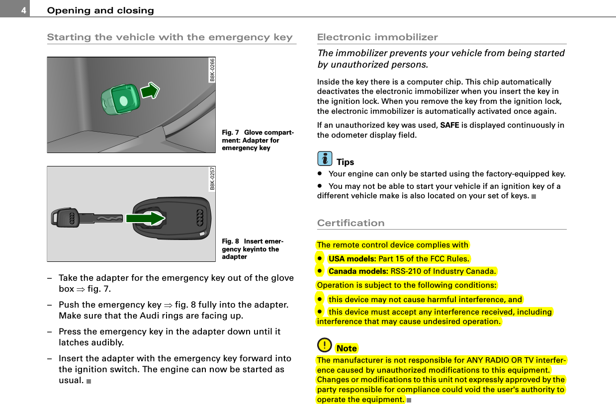
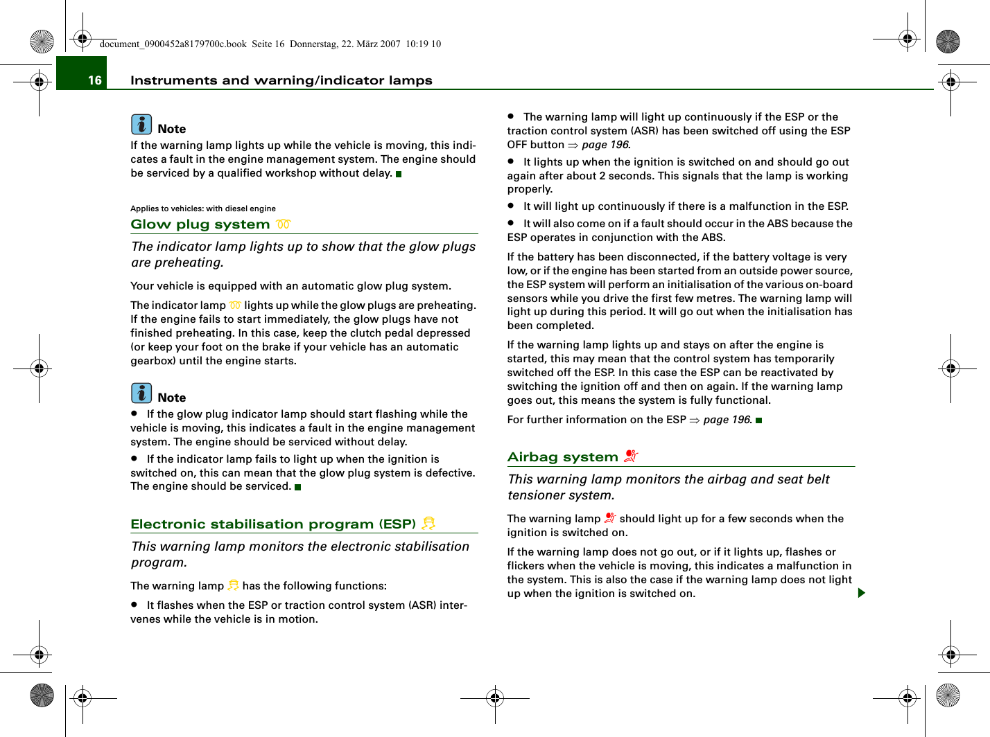
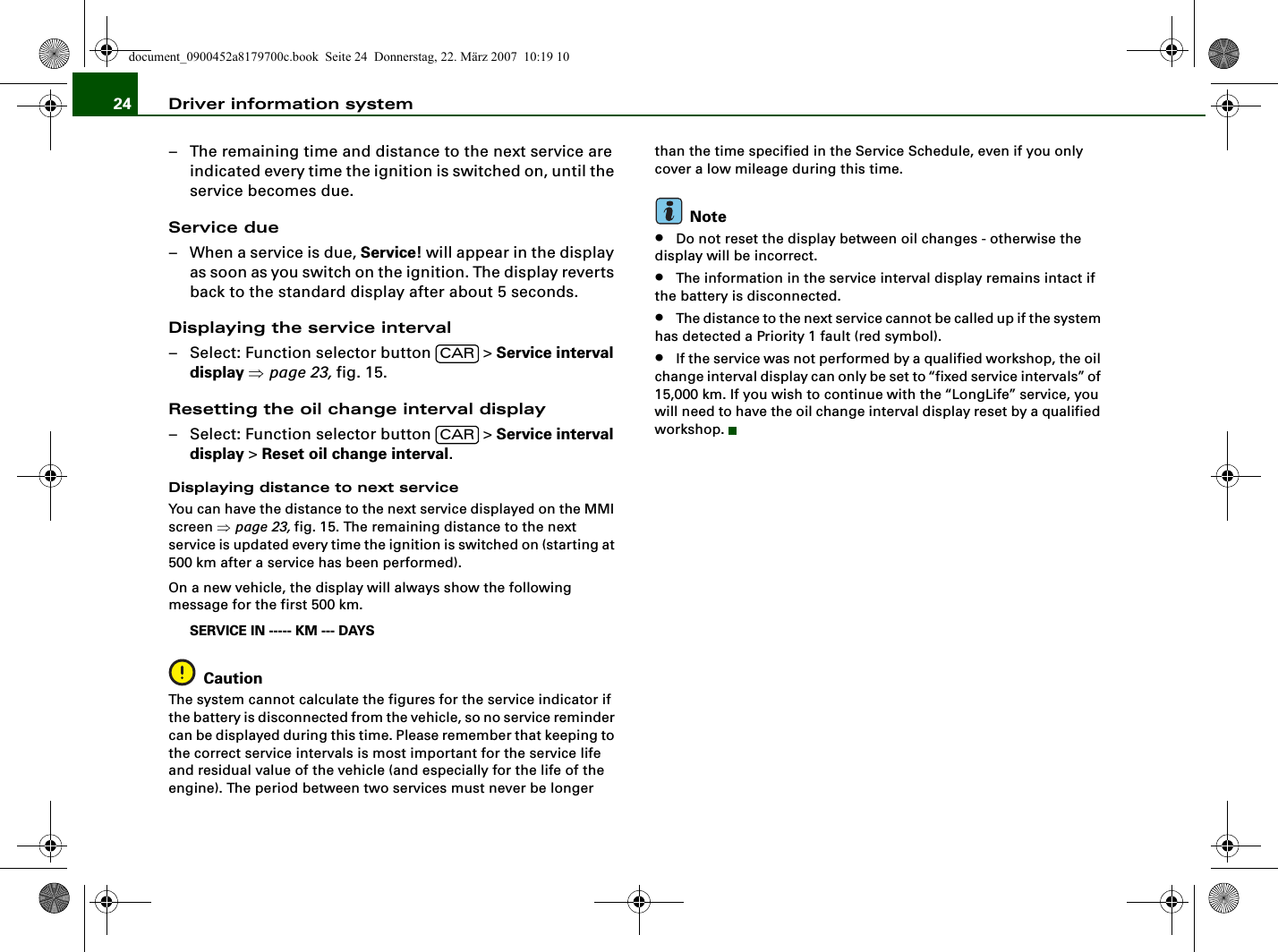
![Opening and closing6Tips•In the event of a crash with airbag deployment all locked doors will be automatically unlocked to give access to the vehicle occu-pants from the outside.•If the power locking system should malfunction, you can lock the driver's door using the mechanical key ⇒page 10.•If the power locking system should fail, you can still open the fuel tank flap in an emergency [Cross reference error: reference link ID='Tankklappe-not' not found].•You are well advised not to keep valuables inside an unattended vehicle, visible or not. Even a properly locked vehicle cannot provide the security of a safe.•If the LED in the upper edge of the driver's door panel comes on for about 30 seconds after the vehicle is locked, there is a malfunc-tion in the power locking or the anti-theft warning system. Have the malfunction corrected by an authorized Audi dealership or qualified repair facility.Setting power lockingThe driver can determine the functions for power locking in the radio or in the MMI*.In the Central locking menu you can decide which doors should be unlocked with the remote key, and/or the advanced key* when opening the vehicle.– Press the function button.– Select Central locking. The Central locking menu appears ⇒fig. 9.For example, if you switch the item “Single door unlocking” on, the passenger's door is no longer included in the power locking system, and will not be unlocked by pressing the unlock button on the master key remote control.You can continue to unlock all the doors and the rear lid as before. Press the opening button on the master key twice.When locking the vehicle, all doors and the trunk lid are locked auto-matically.If you switch “Trunk lid” off, opening the rear lid at the handle ⇒page 11, fig. 17 is blocked. In this case the rear lid can be opened with the button on the master key ⇒fig. 10 or with the unlocking button in the driver's door ⇒page 11, fig. 16.Unlocking and locking the vehicle with the remote controlFig. 9 MMI display: Central locking menuCARFig. 10 Remote control: function buttons](https://usermanual.wiki/HELLA-and-KGaA/BCM2/User-Guide-949797-Page-53.png)
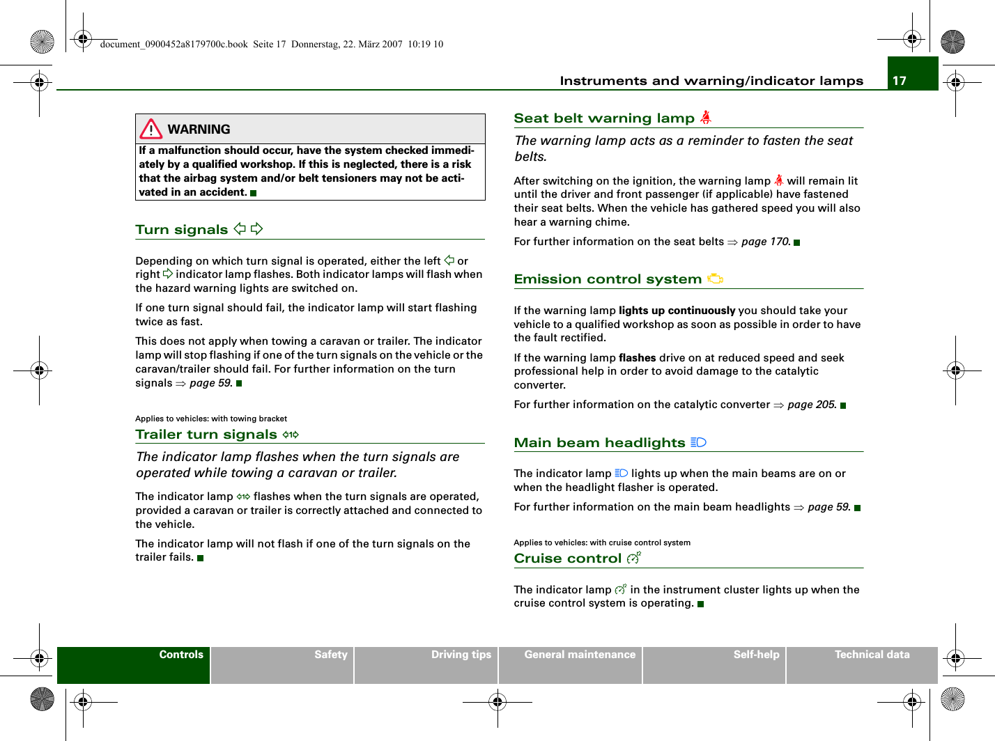
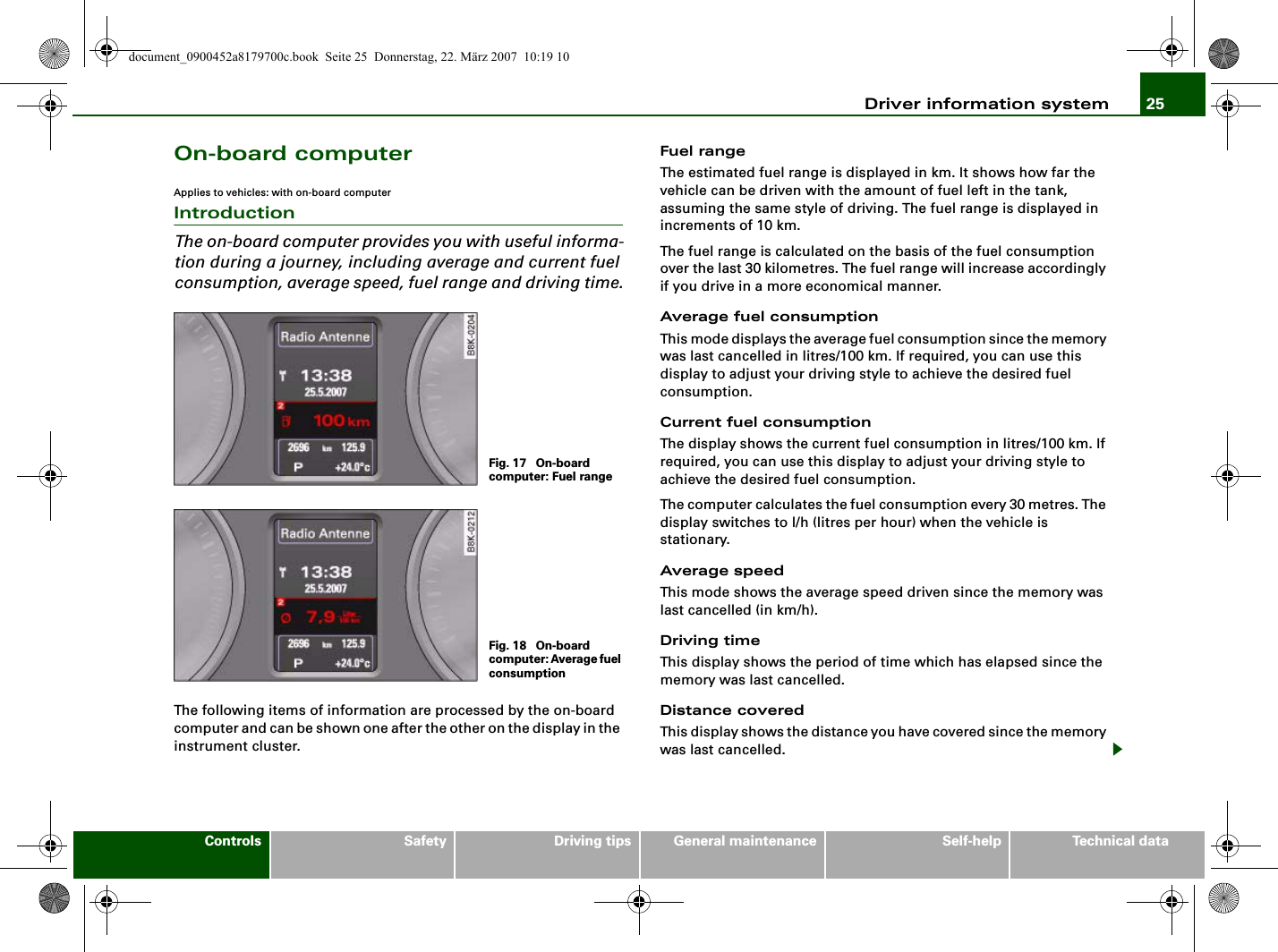
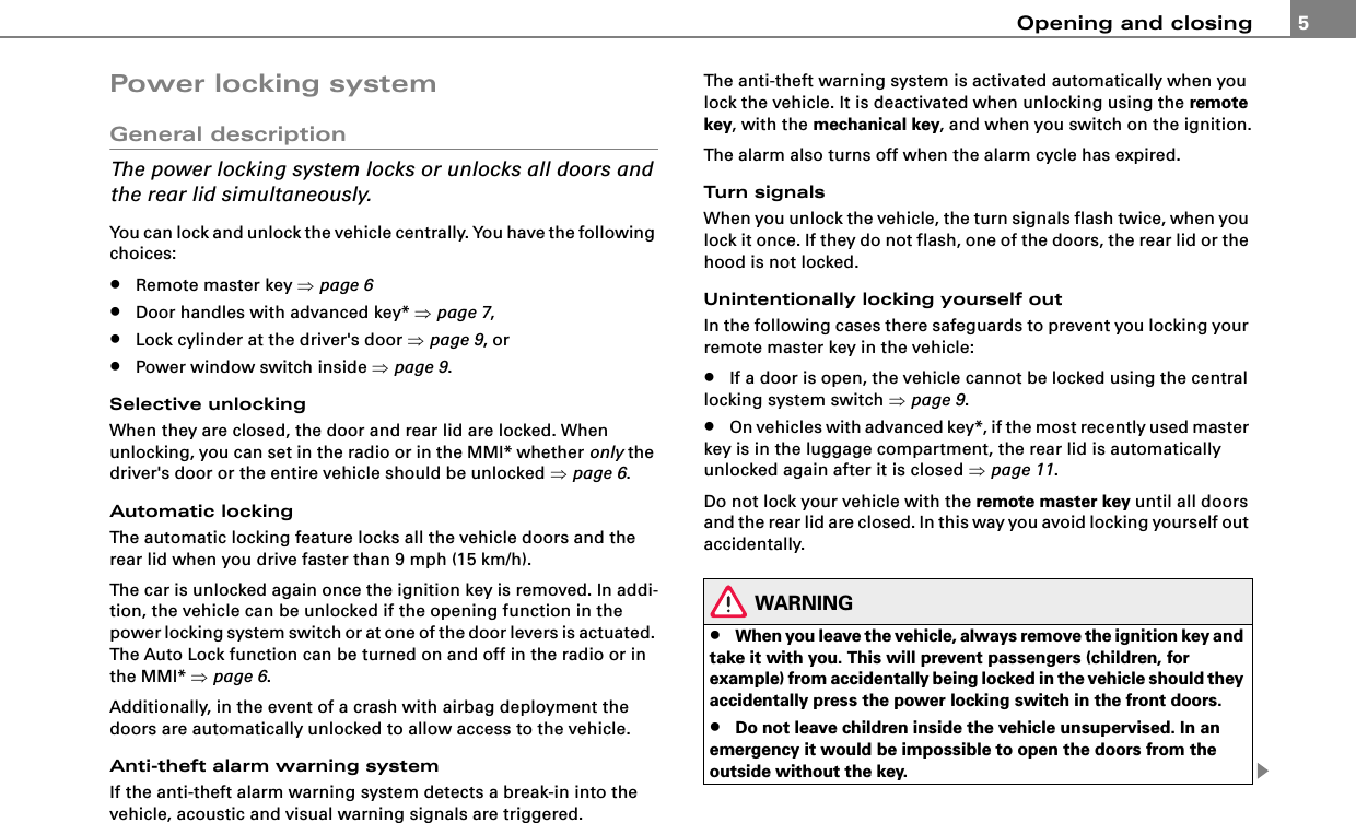
![Opening and closing 11Opening and closing rear lid/trunk lidOpening the rear lid– Press the middle button on the remote control master key for at least one second, or– Pull the release button in the driver's door ⇒fig. 16. The rear lid unlocks and opens, or– Press the handle on the rear lid ⇒fig. 17.Closing the rear lid– Pull the rear lid down at the grip on the inside and allow it to drop gently to close it ⇒.WARNING•After closing the rear lid, always pull up on it to make sure that it is properly closed. Otherwise it could open suddenly when the vehicle is moving.•To help prevent poisonous exhaust gas from being drawn into the vehicle, always keep the rear lid closed while driving. Never transport objects larger than those which fit completely into the luggage area, because then the rear lid cannot be fully closed.•Never leave your vehicle unattended especially with the rear lid left open. A child could crawl into the car through the luggage compartment and pull the lid shut, becoming trapped and unable to get out. To reduce the risk of personal injury, never let children play in or around your vehicle. Always keep the rear lid as well as the vehicle doors closed when not in use.•Always ensure that no one is within range of the rear lid when it is moving, in particular close to the hinges - fingers or hands can be pinched.Tips•When the vehicle is locked, the rear lid can be opened separately by pressing the button on the master key. When you close the rear lid again, it locks automatically.•If the rear lid is open or not properly closed when the ignition is turned on, the door and rear lid warning [Cross reference error: reference link ID='Tuerwarnung' not found] appears in the instru-ment cluster display.Fig. 16 Driver's door: remote rear lid releaseFig. 17 Position of handle in the rear lid](https://usermanual.wiki/HELLA-and-KGaA/BCM2/User-Guide-949797-Page-58.png)