HELLA and KGaA BCM2 Body computer module 2 User Manual Manual
Hella KGaA Hueck & Co. Body computer module 2 Manual
Manual

Annex No.5
Page 1 of 59
Functional description
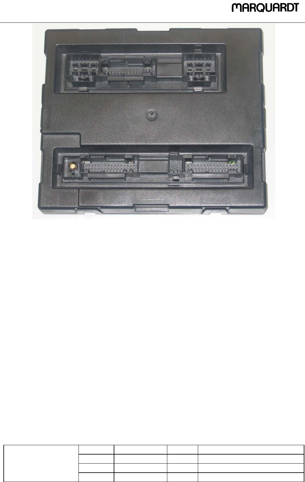
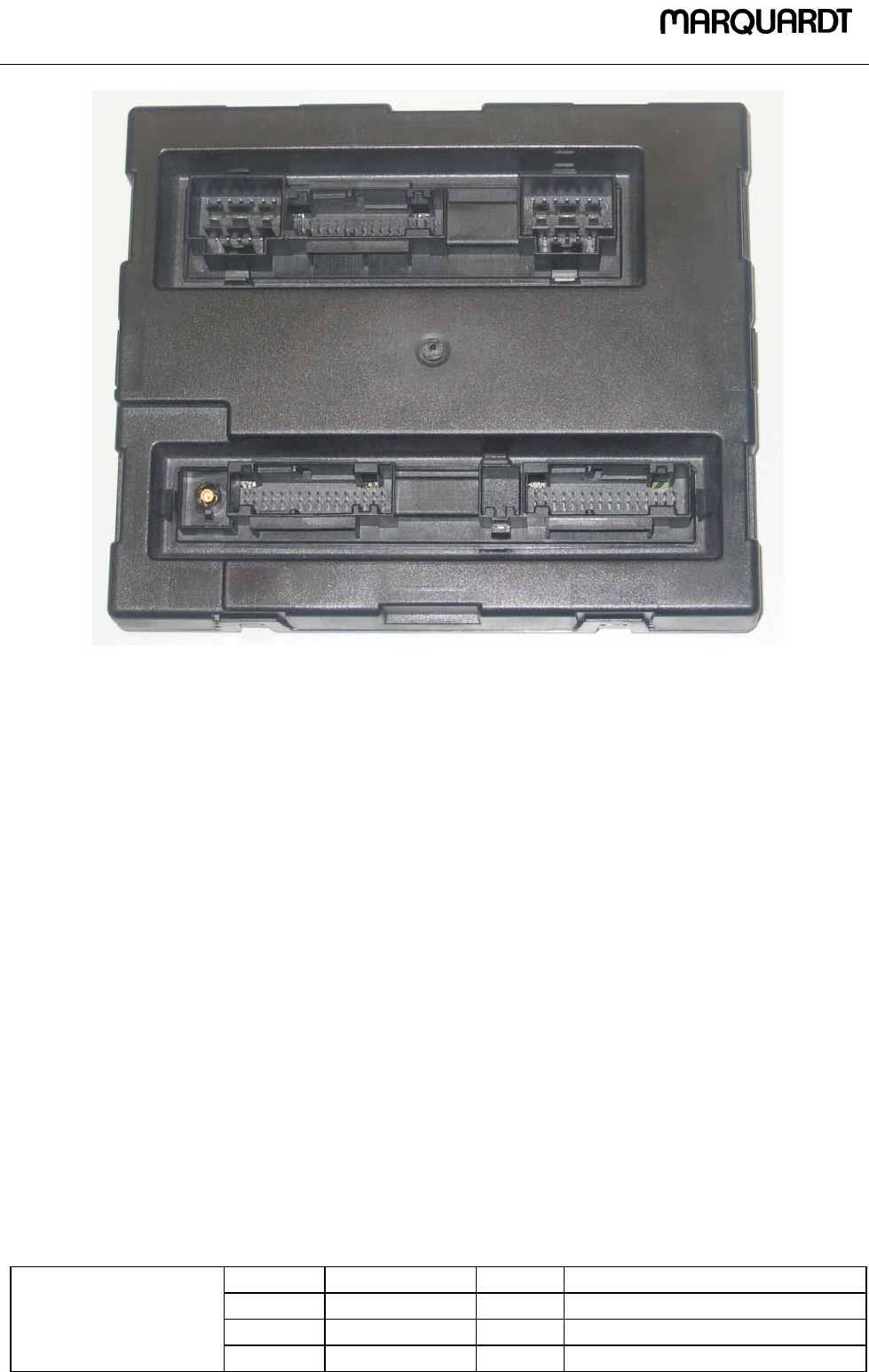
FBSB802 BCM2 B8 315 MHz

!!"##$%!
&' !!"##$%!
( )* (+
#
, #

#
-
-.$/
01231-4(
5)66
- 7!1)($8 )(
-( # 9
5)5-&$:;07
.
Proprietary da ta, com p any confidential. A ll r ights reserve d.
Confié à titre de se c ret d'entre pr is e. T ous droits réservés .
Com u nicado c omo segredo em pr esarial. R eservados todos os d ireitos.
Confidado com o secreto ind ustria l. N os reserv amos todos lo s derec hos.
.
.
W eitergabe sow ie Ver vie lfältigun g dieser U nterlage , Ver
-
w ertung und M itte ilung ihres In halts nich t gestattet, sow eit
nicht ausdr ücklich zuge stande n. Zuw iderhandlun gen ver
-
pflichte n zu Schadene rsatz. Alle R echte vorbehalten , insbe-
sondere für de n Fall der Pa tenterteilun g od er G M-Eintrag ung
.
.
&55<
)&$();0<9)=())
5
;55=&$:9=:95
45)5-
8 .(< $!>7%;
-&$:
?( (<'
;+5= @7%.A
(< B("(* (5C<5D
0 :?$C<)).=D
05
- %@!."E@ ."
-5 8 .:!=C%@!?"D
-#=C@ ."D
&0C((D
8 :$&C!(=)%@!."D
5<5=59=555
;F%&@FG@2H7
C%D
55 <
<)5 1.C5D
I55
59
#
-
-.$/
01231-4(
5)66
- 7!1)($8 )(
-( # 9
5)5-&$:;07
.
Proprietary data, compan y confidential. All r ights re serve d.
Confié à titre de se c re t d'entrepr is e. T ous droits réser vés .
Com u nicado c omo seg r edo em pr esa rial. R eservados todos os d ireitos.
Confidado com o se creto ind ustrial. N os reserv amos todos los d erechos.
.
.
W eitergabe sow ie Ver vie lfältigun g dieser U nterlage , Ver
-
w ertung und M itte ilung ihres In halts nich t gestattet, sow eit
nicht ausdr ücklich zuge stande n. Zuw iderhandlun gen ver
-
pflichte n zu Schadene rsatz. Alle R echte vorbehalten , insbe-
sondere für de n Fall der Pa tenterteilun g od er G M-Eintrag ung
.
.
:5;0

!""#$$%$"
&' !""#$$%("
) * )+
( !
, ( !

( !
-
-.%/
012-3)
4566
-!7 "5)%8 5)
-) ( ! 9
454-&%:;07
.
Proprietary da ta, com p any confidential. A ll r ights reserve d.
Confié à titre de se c ret d'entre pr is e. T ous droits réservés .
Com u nicado c omo segredo em pr esarial. R eservados todos os d ireitos.
Confidado com o secreto ind ustria l. N os reserv amos todos lo s derec hos.
.
.
W eitergabe sow ie Ver vie lfältigun g dieser U nterlage , Ver
-
w ertung und M itte ilung ihres In halts nich t gestattet, sow eit
nicht ausdr ücklich zuge stande n. Zuw iderhandlun gen ver
-
pflichte n zu Schadene rsatz. Alle R echte vorbehalten , insbe-
sondere für de n Fall der Pa tenterteilun g od er G M-Eintrag ung
.
.
&44<
5495;0<95=)554
)4444=49&%<5:9=4
3454-
8 .)< %" >7(;
-&%:
?) )<'
;+4= (@ 0A
"@$0A
77@ 0A
5 B .A
&+4=4 >#%7 <<)
C<4@@)<D
9= =< %$()* (@ 0A
=< %$()* "@$0A
=< %$()* 77@ 0A
0 %&?C+4=5.=D
&+4=9 >#%.A* (0AC>#%( E D
>#%.A* "@$0AC>#%( E D
>#%(.A* 77@0AC>#%( E D
04
- @.#F .#
; 045
-4 )49C@?#D
G%<)>$
8 4454'4
( !
-
-.%/
012-3)
4566
-!7 "5)%8 5)
-) ( ! 9
454-&%:;07
.
Proprietary data, compan y confidential. All r ights re serve d.
Confié à titre de se c re t d'entrepr is e. T ous droits réser vés .
Com u nicado c omo seg r edo em pr esa rial. R eservados todos os d ireitos.
Confidado com o se creto ind ustrial. N os reserv amos todos los d erechos.
.
.
W eitergabe sow ie Ver vie lfältigun g dieser U nterlage , Ver
-
w ertung und M itte ilung ihres In halts nich t gestattet, sow eit
nicht ausdr ücklich zuge stande n. Zuw iderhandlun gen ver
-
pflichte n zu Schadene rsatz. Alle R echte vorbehalten , insbe-
sondere für de n Fall der Pa tenterteilun g od er G M-Eintrag ung
.
.
:4;05&%445

Audi A5 englisch 04.07
Audi A5
Owner's Manual
ärz 2007 10:19 10

© 2007 AUDI AG
AUDI AG works continuously to develop and further improve all
models. You will appreciate that we must therefore reserve the right
to alter any part of the vehicle and its equipment or technical spec-
ifications at any time. No legal commitment can therefore be
implied by the information, illustrations or descriptions in this
Manual.
No part of this Owner's
M
translated without the wr
under the laws of copyri
g
Subject to alteration and
Date of publication: 09.0
3
For the sake of th
e
This paper was bleached
w
M
ärz 2007 10:19 10
Foreword
Thank you for choosing the Audi A5.
The new Audi A5 combines the latest technology with numerous features for your comfort and
convenience. To help you get the best out of these features in everyday use, we recommend that
you read this Manual carefully so you can quickly become familiar with your vehicle in detail.
As well as information on how to use the controls and equipment, the Owner's Manual contains
important notes on care and maintenance. These are relevant to your safety and will help preserve
your car's value. The Manual also offers useful driving tips and advice, together with some sugges-
tions on how to drive your car with minimum impact on the environment.
In addition to this Owner's Manual, the Service Wallet also includes the Service Schedule for your
vehicle. This booklet contains important information on Audi service requirements and lists the
vehicle's fuel consumption figures. The Service Wallet also includes operating manuals for
optional on-board systems such as the radio, navigation and telephone. We recommend that you
keep the Service Wallet in the car at all times.
Should you have any further questions regarding your car or if you suspect that your owner's liter-
ature is not complete, please contact your Audi dealer or importer. They are always glad to answer
your queries and note any suggestions you may have.
We wish you safe and enjoyable motoring with your Audi A5.
AUDI AG
document_0900452a8179700c.book Seite 1 Donnerstag, 22. März 2007 10:19 10
Contents2
Contents
Notes on this Owner's
Manual . . . . . . . . . . . . . . . . . . . . . .
Controls . . . . . . . . . . . . . . . . . . . . .
Controls and displays . . . . . . . . . .
Overview . . . . . . . . . . . . . . . . . . . . . .
Instruments and
warning/indicator lamps . . . . . . .
Instruments . . . . . . . . . . . . . . . . . . . .
Warning and indicator lamps . . . . .
Driver information system . . . . . .
Introduction . . . . . . . . . . . . . . . . . . . .
On-board computer . . . . . . . . . . . . .
Speed warning function . . . . . . . . .
Auto-check control . . . . . . . . . . . . . .
Doors and windows . . . . . . . . . . . .
Remote control keys . . . . . . . . . . . .
Central locking system . . . . . . . . . .
Boot lid . . . . . . . . . . . . . . . . . . . . . . . .
Electric windows . . . . . . . . . . . . . . .
Tilting panorama roof . . . . . . . . . . .
Lights and vision . . . . . . . . . . . . . . .
Lights . . . . . . . . . . . . . . . . . . . . . . . . .
Interior lights . . . . . . . . . . . . . . . . . . .
Clear vision . . . . . . . . . . . . . . . . . . . .
Windscreen wipers . . . . . . . . . . . . . .
Rear-view mirrors . . . . . . . . . . . . . .
Digital compass . . . . . . . . . . . . . . . .
Seats and storage . . . . . . . . . . . . .
Manual adjustment of front seats
Easy-entry function . . . . . . . . . . . . .
Electric adjustment of front seats
Easy-entry function . . . . . . . . . . . . .
Seat memory . . . . . . . . . . . . . . . . . .
Head restraints . . . . . . . . . . . . . . . .
Front armrest . . . . . . . . . . . . . . . . . .
Luggage compartment . . . . . . . . .
Roof carrier . . . . . . . . . . . . . . . . . . . .
Cup holders . . . . . . . . . . . . . . . . . . .
Ashtrays . . . . . . . . . . . . . . . . . . . . . .
Cigarette lighter and electrical
sockets . . . . . . . . . . . . . . . . . . . . . . .
On-board 230 Volt Euro socket . . .
Storage compartments . . . . . . . . .
Heating and cooling . . . . . . . . . . .
Deluxe automatic air conditioner .
Deluxe automatic air conditioner -
basic settings . . . . . . . . . . . . . . . . . .
Deluxe automatic air conditioner
plus . . . . . . . . . . . . . . . . . . . . . . . . . .
Deluxe automatic air conditioner
plus - basic settings . . . . . . . . . . . .
Auxiliary heating and auxiliary
ventilation . . . . . . . . . . . . . . . . . . . . .
Seat heating . . . . . . . . . . . . . . . . . . .
Driving . . . . . . . . . . . . . . . . . . . . . . . . .
Steering . . . . . . . . . . . . . . . . . . . . . . .
Ignition lock . . . . . . . . . . . . . . . . . . .
Starting and stopping the engine
with the advanced key . . . . . . . . . .
Electro-mechanical parking brake
Cruise control system . . . . . . . . . .
Automatic gearbox . . . . . . . . . . . . .
multitronic® . . . . . . . . . . . . . . . . . . .
Audi parking system . . . . . . . . . . .
Parking aid systems . . . . . . . . . . . .
parking system . . . . . . . . . . . . . . . . .
parking system plus . . . . . . . . . . . .
parking system advanced . . . . . . .
Towing bracket . . . . . . . . . . . . . . . . .
Settings . . . . . . . . . . . . . . . . . . . . . . .
Special parking situations . . . . . . .
Safety notes . . . . . . . . . . . . . . . . . . .
HomeLink . . . . . . . . . . . . . . . . . . . . . .
Universal transmitter . . . . . . . . . . . .
Safety . . . . . . . . . . . . . . . . . . . . . . .
Safe driving . . . . . . . . . . . . . . . . . . . .
General notes . . . . . . . . . . . . . . . . . .
Correct sitting positions . . . . . . . . .
Pedal area . . . . . . . . . . . . . . . . . . . . .
Stowing luggage safely . . . . . . . . .
Seat belts . . . . . . . . . . . . . . . . . . . . . .
Why is it so important to use seat
belts? . . . . . . . . . . . . . . . . . . . . . . . . .
Forces acting in a collision . . . . . .
How to wear seat belts properly .
Belt tensioners . . . . . . . . . . . . . . . . .
5
7
9
9
11
11
15
20
20
25
28
29
39
39
42
48
50
52
54
54
60
61
62
65
68
70
70
71
72
73
74
76
77
77
84
85
86
87
89
91
93
93
100
101
109
111
115
116
116
116
118
121
125
130
130
137
137
137
138
140
147
148
150
152
154
154
161
162
162
164
167
168
170
170
171
173
175
document_0900452a8179700c.book Seite 2 Donnerstag, 22. März 2007 10:19 10
Contents 3
Controls Safety Driving tips General maintenance Self-help Technical data
Airbag system . . . . . . . . . . . . . . . . .
Description of airbag system . . . .
Front airbags . . . . . . . . . . . . . . . . . .
Side airbags . . . . . . . . . . . . . . . . . . .
Head-protection airbags
(sideguard) . . . . . . . . . . . . . . . . . . . .
Deactivating the front passenger's
airbag via the key-operated switch
Child safety . . . . . . . . . . . . . . . . . . . .
Points to remember if children are
travelling in the car . . . . . . . . . . . . .
Child safety seats . . . . . . . . . . . . . .
Fitting child safety seats . . . . . . . .
Driving tips . . . . . . . . . . . . . . . .
Intelligent technology . . . . . . . . . .
Electronic stabilisation program
(ESP) . . . . . . . . . . . . . . . . . . . . . . . . . .
Brakes . . . . . . . . . . . . . . . . . . . . . . . .
Power steering (servotronic) . . . . .
Four-wheel drive (quattro®) . . . . . .
Power management . . . . . . . . . . . .
Your vehicle and the
environment . . . . . . . . . . . . . . . . . . .
Running in . . . . . . . . . . . . . . . . . . . .
Emission control systems . . . . . . .
Driving abroad . . . . . . . . . . . . . . . . .
How to improve economy and
minimise pollution . . . . . . . . . . . . .
Environmental compatibility . . . . .
Towing a trailer . . . . . . . . . . . . . . . .
Driving the vehicle with a trailer or
caravan . . . . . . . . . . . . . . . . . . . . . . .
Removable towing bracket . . . . . .
General maintenance . .
Care of vehicle and cleaning . . .
General notes . . . . . . . . . . . . . . . . . .
Care of exterior . . . . . . . . . . . . . . . . .
Care of interior . . . . . . . . . . . . . . . . .
Fuel and filling the tank . . . . . . . .
Petrol . . . . . . . . . . . . . . . . . . . . . . . . .
Diesel . . . . . . . . . . . . . . . . . . . . . . . . .
Filling the tank . . . . . . . . . . . . . . . . .
Checking and topping up fluids
Bonnet . . . . . . . . . . . . . . . . . . . . . . . .
Engine compartment layout . . . . .
Engine oil . . . . . . . . . . . . . . . . . . . . . .
Cooling system . . . . . . . . . . . . . . . . .
Brake fluid . . . . . . . . . . . . . . . . . . . . .
Battery . . . . . . . . . . . . . . . . . . . . . . . .
Windscreen washer . . . . . . . . . . . . .
Wheels and tyres . . . . . . . . . . . . . . .
Wheels . . . . . . . . . . . . . . . . . . . . . . . .
Accessories and modifications
to the vehicle . . . . . . . . . . . . . . . . . . .
Accessories and replacement
parts . . . . . . . . . . . . . . . . . . . . . . . . . .
Modifications . . . . . . . . . . . . . . . . . .
Radio transmitters and business
equipment . . . . . . . . . . . . . . . . . . . . .
Self-help . . . . . . . . . . . . . . . . . . . . .
Self-help . . . . . . . . . . . . . . . . . . . . . . . .
Warning triangle . . . . . . . . . . . . . . . .
First-aid kit . . . . . . . . . . . . . . . . . . . . .
Fire extinguisher . . . . . . . . . . . . . . . .
Too ls and Tyre Mobil ity System . . .
Compact temporary spare wheel*
Tyre repairs . . . . . . . . . . . . . . . . . . . .
Changing a wheel . . . . . . . . . . . . . .
Jump-starting . . . . . . . . . . . . . . . . . .
Tow-starting and towing away . . .
Fuses and bulbs . . . . . . . . . . . . . . . .
Fuses . . . . . . . . . . . . . . . . . . . . . . . . . .
Bulbs . . . . . . . . . . . . . . . . . . . . . . . . . .
Changing bulbs for headlights . . .
Changing bulb for turn signals . . .
Changing bulb for side lights . . . . .
Changing bulb for front fog lights
Changing bulbs for rear lights in
side panel . . . . . . . . . . . . . . . . . . . . . .
Changing bulbs in boot lid . . . . . . .
Number plate light . . . . . . . . . . . . . .
176
176
178
180
181
183
185
185
186
189
195
196
196
199
201
201
202
205
205
205
205
206
207
208
208
211
219
220
220
220
223
227
227
227
228
230
230
232
233
235
238
239
242
243
243
250
250
250
251
253
254
254
254
255
255
256
257
260
265
267
272
272
276
278
282
282
283
284
286
288
document_0900452a8179700c.book Seite 3 Donnerstag, 22. März 2007 10:19 10
Contents4
Technical data . . . . . . . . . . . .
General notes . . . . . . . . . . . . . . . . . .
Explanation of technical data . . . .
Dimensions . . . . . . . . . . . . . . . . . . . .
Capacities . . . . . . . . . . . . . . . . . . . . .
Vehicle identification data . . . . . . .
Performance, weights and
dimensions . . . . . . . . . . . . . . . . . . . . .
Petrol engines . . . . . . . . . . . . . . . . . .
Diesel engines . . . . . . . . . . . . . . . . . .
Index . . . . . . . . . . . . . . . . . . . . . . . . .
291
292
292
292
293
293
295
295
297
301
document_0900452a8179700c.book Seite 4 Donnerstag, 22. März 2007 10:19 10
Notes on this Owner's Manual 5
Controls Safety Driving tips General maintenance Self-help Technical data
Notes on this Owner's Manual
This Owner's Manual contains important information, tips, sugges-
tions and warnings.
Please ensure that this Owner's Manual is always kept in the vehicle.
It should always be available to anyone else driving the vehicle, i.e.
anyone renting, borrowing or buying the vehicle from you.
This manual describes the equipment available for the vehicle at the
time of going to print. Some of the equipment described here will
not be available until a later date, or may only be available in certain
markets.
Some sections of this Owner's Manual do not apply to all vehicles.
If this is the case, a text at the start of the section indicates which
vehicles it applies to, e. g. “Applies to vehicles: with auxiliary
heater”. This optional equipment is also marked with an asterisk “*”.
Illustrations are intended as a general guide, and may vary from the
equipment fitted in your vehicle in some details.
At the beginning of this Owner's Manual, you will find a table of
contents showing all the items described in this manual in the order
in which they appear. An alphabetical index is included at the end
of the Owner's Manual.
All references to positions such as “left”, “right”, “front” or “rear”
are given as seen facing in the direction of travel.
* optional equipment
The section is continued on the following page.
Denotes the end of a section.
®Registered trademarks are marked ®. However, the absence of
this symbol does not constitute a waiver of the rights
concerning any proprietary name.
⇒ Refers to a “WARNING” within the same section. If the
WARNING symbol is followed by a page number the warning text
referred to is included in a different section.
WARNING
Texts with this symbol contain safety information. They warn you
of serious dangers, possibly involving accident or injury.
Caution
Texts with this symbol draw your attention to a possible risk of
damage to your vehicle.
For the sake of the environment
Texts with this symbol refer to points relevant to the protection of
the environment.
Note
Texts with this symbol contain additional information of a more
general nature.
document_0900452a8179700c.book Seite 5 Donnerstag, 22. März 2007 10:19 10

6
document_0900452a8179700c.book Seite 6 Donnerstag, 22. März 2007 10:19 10
7Controls
document_0900452a8179700c.book Seite 7 Donnerstag, 22. März 2007 10:19 10
Controls and displays8
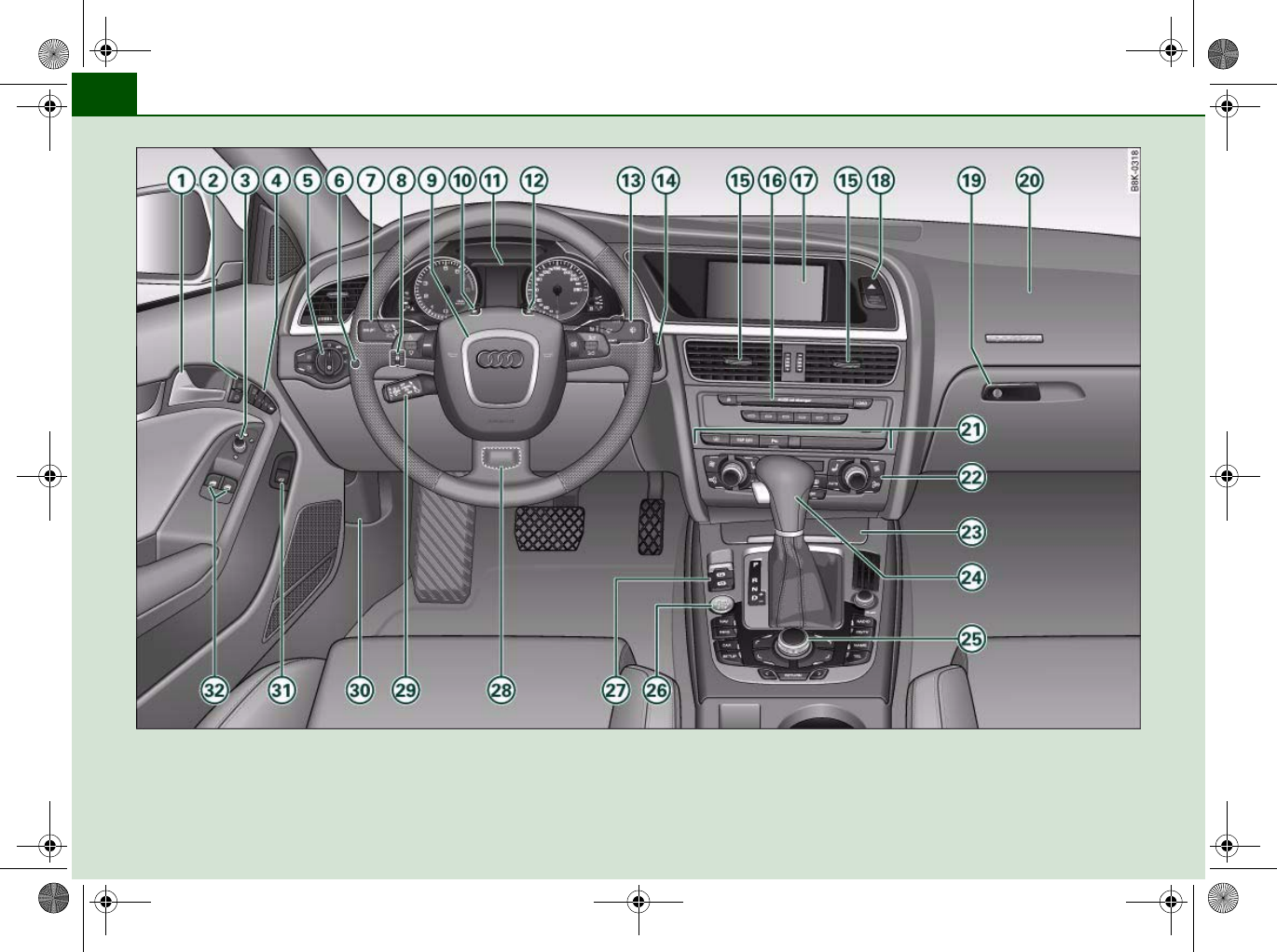
Fig. 1 Some of the items of equipment listed in this section are only fitted on certain models or are optional extras.
document_0900452a8179700c.book Seite 8 Donnerstag, 22. März 2007 10:19 10
Controls and displays 9
Controls Safety Driving tips General maintenance Self-help Technical data
Controls and displays
Overview
Door handle
Central locking switch . . . . . . . . . . . . . . . . . . . . . . . . . . .
Electric adjuster for exterior mirrors . . . . . . . . . . . . . . .
Seat memory . . . . . . . . . . . . . . . . . . . . . . . . . . . . . . . . . .
Light switch . . . . . . . . . . . . . . . . . . . . . . . . . . . . . . . . . . .
Instrument lighting . . . . . . . . . . . . . . . . . . . . . . . . . . . . .
Lever for turn signals and main beam headlights . . . .
Headlight range control . . . . . . . . . . . . . . . . . . . . . . . . .
Steering wheel with:
−Horn
−Driver's airbag . . . . . . . . . . . . . . . . . . . . . . . . . . . . . . .
−Controls for audio, TV*, telephone and speech
dialogue system*
−Paddle levers for tiptronic gearshift . . . . . . . . . . . . .
SET button . . . . . . . . . . . . . . . . . . . . . . . . . . . . . . . . . . . .
Instrument cluster . . . . . . . . . . . . . . . . . . . . . . . . . . . . . .
Reset button for trip recorder . . . . . . . . . . . . . . . . . . . .
Control lever for:
−Windscreen wipers and washer . . . . . . . . . . . . . . . . .
−On-board computer . . . . . . . . . . . . . . . . . . . . . . . . . . .
Ignition lock . . . . . . . . . . . . . . . . . . . . . . . . . . . . . . . . . . .
Air outlets with thumbwheel . . . . . . . . . . . . . . . . . . . . .
−For deluxe automatic air conditioner . . . . . . . . . . . .
−For deluxe automatic air conditioner plus . . . . . . . .
Depending on equipment fitted:
−Radio
−CD changer
Depending on equipment fitted:
−Radio display
−MMI display 1)
Hazard warning lights
Glove box . . . . . . . . . . . . . . . . . . . . . . . . . . . . . . . . . . . . .
Front passenger's airbag . . . . . . . . . . . . . . . . . . . . . . . . .
Switches for the following (as applicable):
−Audi parking system . . . . . . . . . . . . . . . . . . . . . . . . . .
−Electronic Stabilisation Program (ESP) . . . . . . . . . . .
−Electric sun blind . . . . . . . . . . . . . . . . . . . . . . . . . . . . .
Air conditioner, depending on equipment fitted:
−Deluxe automatic air conditioner . . . . . . . . . . . . . . . .
−Deluxe automatic air conditioner plus . . . . . . . . . . .
Ashtray with cigarette lighter . . . . . . . . . . . . . . . . . . . . .
Depending on gearbox fitted, gear lever or selector
lever for:
−multitronic® . . . . . . . . . . . . . . . . . . . . . . . . . . . . . . . . .
−Manual gearbox
Depending on equipment fitted:
−MMI control console or
−Switch for Audi parking system . . . . . . . . . . . . . . . . .
−Switch for Electronic Stabilisation Program (ESP
OFF) . . . . . . . . . . . . . . . . . . . . . . . . . . . . . . . . . . . . . . . .
−Switch for electric sun blind . . . . . . . . . . . . . . . . . . . .
Start/stop button . . . . . . . . . . . . . . . . . . . . . . . . . . . . . . .
Electro-mechanical parking brake . . . . . . . . . . . . . . . . .
A
1
A
247
A
367
A
474
A
554
A
657
A
759
A
857
A
9
178
135
A
10 12
A
11 11
A
12 14
A
13
62
25
A
14 116
A
15 108
99
108
A
16
A
17
1) Depending on the MMI system fitted in your vehicle the display screen is
either two-coloured or multi-coloured. As the two displays are more or less
identical this Owner's Manual uses the multi-coloured displays for illustra-
tion purposes.
A
18
A
19 91
A
20 178
A
21
138
196
61
A
22
93
101
A
23 86, 87
A
24
130
A
25
138
196
61
A
26 118
A
27 121
document_0900452a8179700c.book Seite 9 Donnerstag, 22. März 2007 10:19 10
Controls and displays10
Adjustable steering column (hidden behind steering
wheel) . . . . . . . . . . . . . . . . . . . . . . . . . . . . . . . . . . . . . . . .
Cruise control system . . . . . . . . . . . . . . . . . . . . . . . . . . .
Bonnet lock release . . . . . . . . . . . . . . . . . . . . . . . . . . . .
Switch for releasing the boot lid . . . . . . . . . . . . . . . . . .
Electric windows . . . . . . . . . . . . . . . . . . . . . . . . . . . . . . .
Note
•Please refer to the separate operating manual for instructions on
using the Multi Media Interface (MMI).
•The arrangement of switches and controls on right-hand drive
models* may be slightly different from the layout shown in the illus-
tration ⇒page 8, fig. 1. However, the symbols used to identify the
controls are the same.
A
28
116
A
29 125
A
30 230
A
31 48
A
32 50
document_0900452a8179700c.book Seite 10 Donnerstag, 22. März 2007 10:19 10
Instruments and warning/indicator lamps 11
Controls Safety Driving tips General maintenance Self-help Technical data
Instruments and warning/indicator lamps
Instruments
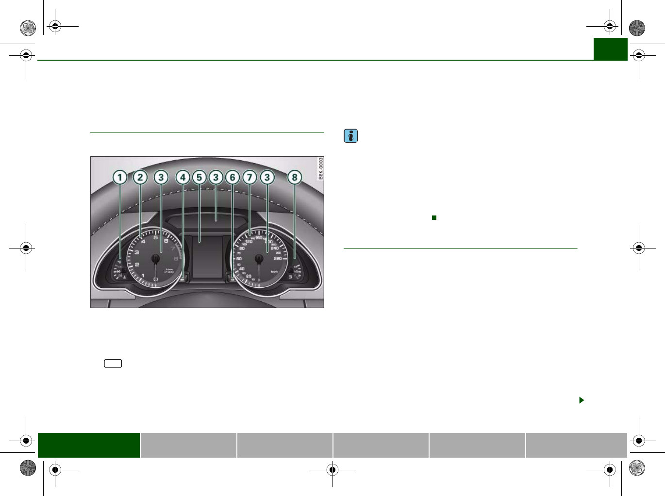
Instrument cluster overview
The instrument cluster is the driver's information centre.
Fig. 2 Overview of instrument cluster
Coolant temperature gauge . . . . . . . . . . . . . . . . . . . . . .
Rev counter . . . . . . . . . . . . . . . . . . . . . . . . . . . . . . . . . . .
Warning and indicator lamps . . . . . . . . . . . . . . . . . . . . .
button . . . . . . . . . . . . . . . . . . . . . . . . . . . . . . . . . . .
Display
−Driver information system . . . . . . . . . . . . . . . . . . . . .
−Date and time display . . . . . . . . . . . . . . . . . . . . . . . . .
−Mileage recorder . . . . . . . . . . . . . . . . . . . . . . . . . . . . .
Reset button for trip recorder . . . . . . . . . . . . . . . . . . . .
Speedometer
Fuel gauge . . . . . . . . . . . . . . . . . . . . . . . . . . . . . . . . . . . .
Note
•The needles in the instrument cluster will sweep across the dials
when you switch on the ignition.
•The instrument lighting (illumination of dials and needles) is
switched on when the ignition is on and the vehicle's lights are off.
The instrument lighting is dimmed automatically as the daylight
starts to fade. This function is intended to remind the driver to
switch on the dipped-beam headlights in good time when light
conditions become poor.
Coolant temperature gauge
The coolant temperature gauge ⇒fig. 2 only works when the
ignition is switched on. In order to avoid possible damage to the
engine, please read the following notes for the different tempera-
ture ranges.
Engine cold
If the needle is still in the lower range of the dial, this indicates that
the engine has not yet reached operating temperature. Avoid high
engine speeds, full acceleration and heavy engine loads.
Normal temperature
In normal operation the needle will settle somewhere in the centre
of the dial once the engine has reached operating temperature. The
needle may also go further up when the engine is working hard at
high outside temperatures. This is no cause for concern provided
the warning symbol in the display does not start flashing.
A
111
A
212
A
315
A
4SET 12
A
5
20
13
14
A
614
A
7
A
819
A
1
document_0900452a8179700c.book Seite 11 Donnerstag, 22. März 2007 10:19 10
Instruments and warning/indicator lamps12
Warning symbol in instrument cluster
If the symbol lights up in the display, this means that either the
coolant temperature is too high or the coolant level is too low
⇒page 32.
If the needle is at the top end of the dial, this means the coolant
temperature is too high. Stop the vehicle, switch off the engine and
wait for it to cool down. If the warning lamp starts flashing again
after just a short distance, contact a qualified workshop.
WARNING
•Before opening the bonnet and checking the coolant level,
please observe the warning information on ⇒page 231, “Working
on components in the engine compartment”.
•Never open the bonnet if you can see or hear steam or coolant
escaping from the engine compartment; there is a risk of being
scalded. Wait until you can no longer see or hear escaping steam
or coolant.
Caution
•Additional lights and other accessories in front of the air inlet
reduce the cooling effect of the radiator. At high outside tempera-
tures and high engine loads, there is a risk of the engine over-
heating.
•The front spoiler also ensures proper distribution of the cooling
air when the vehicle is moving. If the spoiler is damaged this can
reduce the cooling effect, which could cause the engine to overheat.
You should obtain professional assistance.
Rev counter
The rev counter indicates the number of engine revolu-
tions per minute.
You should select a lower gear if the engine speed drops below
1500 rpm. The start of the red zone on the dial indicates the
maximum engine speed which may be used briefly when the engine
is warm and after it has been run in properly. However, it is advisable
to change up a gear or move the selector lever to “D” (or lift your
foot off the accelerator) before the needle reaches the red zone.
Caution
Never allow the rev counter needle ⇒page 11, fig. 2 to go into
the red zone on the dial for more than a very brief period: there is a
risk of damaging the engine. The start of the red zone on the dial is
different for some engine versions.
For the sake of the environment
Changing up a gear early will help you to save fuel and minimise
engine noise.
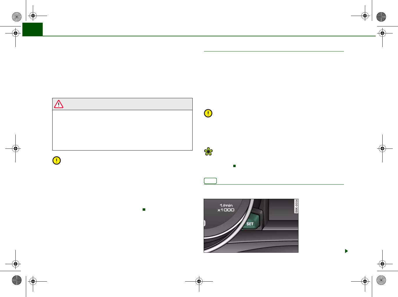
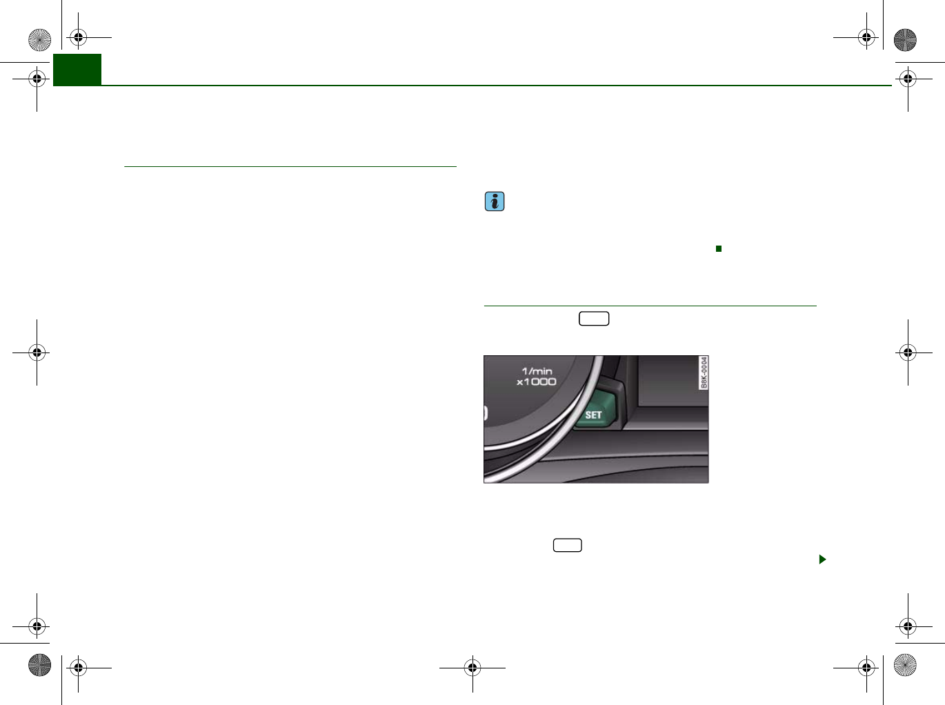
button
This button has a number of different functions.
A
2
SET
Fig. 3 Instrument
cluster: SET button
document_0900452a8179700c.book Seite 12 Donnerstag, 22. März 2007 10:19 10
Instruments and warning/indicator lamps 13
Controls Safety Driving tips General maintenance Self-help Technical data
The button has the following functions:
Activating clock, date, temperature and mileage
recorder displays
The display will appear for about 30 seconds if you press the
button ⇒page 12, fig. 3 when the ignition is switched off.
Starting check procedure (auto-check control)
The auto-check control checks important components and vehicle
systems. These background checks are run constantly, as long as
the ignition is switched on ⇒page 29.
You can start the “check procedure” manually by pressing the
button with the ignition switched on. This function check can be
started at road speeds up to 5 km/h.
Calling up driver messages again
A red or yellow symbol appearing in the instrument cluster display
is normally accompanied by a corresponding message. The
message will disappear from the display after about 5 seconds. If
required, you can call up the message again by briefly pressing the
button.
Setting speed warning
You can press the button briefly to set speed limit warning 1
while the vehicle is moving ⇒page 28. If you press and hold the
button, this will cancel the speed warning.
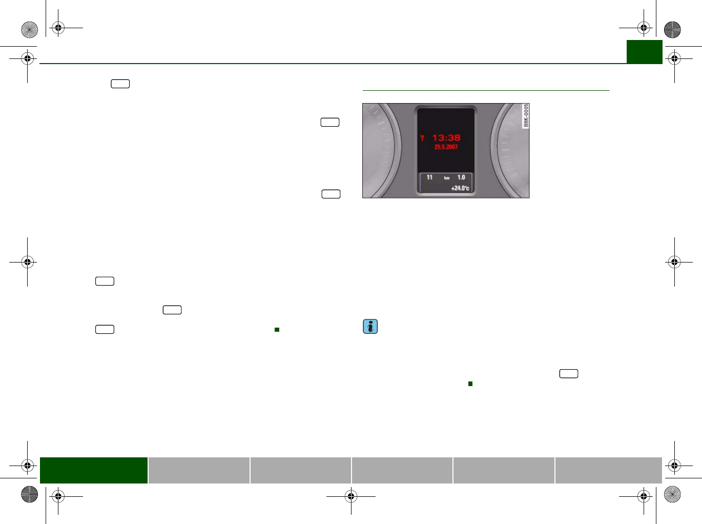
Time and date display
Quartz clock
The date, time and display format can be changed using the sound
system or MMI* control console. Please refer to the Operating
Manual for the MMI or sound system for more details.
Radio-controlled clock*
When the clock is in “radio-control” mode the signal reception
symbol (a radio tower with radio waves) appears in the display
⇒fig. 4. It is then not possible to change the minutes or the date
manually.
Note
•The digital clock and mileage recorder displays are switched on
for about 30 seconds when the driver's door is opened.
•When the ignition is switched off, the clock and date display can
be switched on for about 30 seconds by pressing the button
⇒page 12, fig. 3 ⇒page 12.
SET
SET
SET
SET
SET
SET
Fig. 4 Instrument
cluster: Time and date
display
SET
document_0900452a8179700c.book Seite 13 Donnerstag, 22. März 2007 10:19 10
Instruments and warning/indicator lamps14
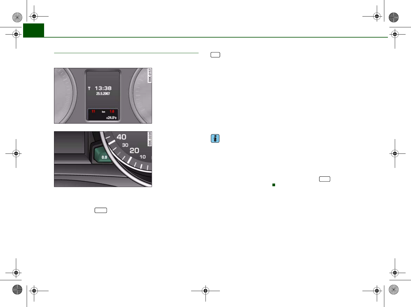
Mileage recorder
The instrument shows how far you have travelled.
The mileage is stated in kilometres (“km”) or “miles”.
You can switch the display from kilometres to miles and vice versa
via the MMI or the button on the sound system control
console.
Odometer / trip recorder
The odometer records the vehicle's total mileage.
The trip recorder shows the distance that has been travelled since it
was last reset. It is used to measure individual journeys. The last
digit of the trip recorder indicates distances of 100 metres or tenths
of a mile.
The trip recorder can be reset to zero by pressing the reset button
⇒fig. 6.
Fault display
If there is a fault in the instruments, the letters dEF appear perma-
nently in the trip recorder display. Please have the fault rectified as
soon as possible.
Immobiliser
When the ignition is switched on, the security programming of the
ignition key is verified electronically.
If an uncoded key is used, SAFE will appear continuously in the
mileage recorder display. The vehicle cannot then be driven
⇒page 39.
Note
•The date, time and recorded mileage will continue to be
displayed for about 30 seconds after you switch off the ignition.
•The digital clock and mileage recorder displays are switched on
for about 30 seconds when the driver's door is opened.
•When the ignition is switched off, the mileage recorder can be
switched on for about 30 seconds by pressing the button
⇒page 12, fig. 3 ⇒page 12.
Fig. 5 Instrument
cluster: Mileage
recorder
Fig. 6 Instrument
cluster: Reset button
CAR
0.0
SET
document_0900452a8179700c.book Seite 14 Donnerstag, 22. März 2007 10:19 10
Instruments and warning/indicator lamps 15
Controls Safety Driving tips General maintenance Self-help Technical data
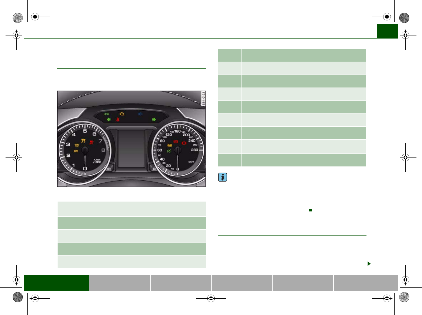
Warning and indicator lamps
Overview
The warning and indicator lamps indicate a number of
different functions and possible faults.
Fig. 7 Instrument cluster with warning and indicator lamps
Note
A number of functions are monitored by the auto-check control
⇒page 20. If a malfunction should occur, this will be shown by the
display in the instrument cluster either with a red symbol (priority 1
– serious malfunction) or a yellow symbol (priority 2 – other
malfunction or item requiring attention).
Applies to vehicles: with petrol engine
Engine management
This warning lamp monitors the engine management
system on petrol engines.
The warning lamp (Electronic Power Control) lights up when the
ignition is switched on to show that the lamp is working properly.
Engine management (alternative
to )
⇒page 15
(alternative to )⇒page 16
Electronic stabilisation program (ESP) ⇒page 16
Airbag system ⇒page 16
Left turn signals ⇒page 17
Trailer turn signals* ⇒page 17
Seat belt warning lamp ⇒page 17
Emission control system ⇒page 17
Main beam headlights ⇒page 17
Right turn signals ⇒page 17
Cruise control system* ⇒page 17
Anti-lock brake system (ABS) ⇒page 18
Electro-mechanical parking
brake/Audi hold assist*
⇒page 19
Fault in brake system ⇒page 19
document_0900452a8179700c.book Seite 15 Donnerstag, 22. März 2007 10:19 10
Instruments and warning/indicator lamps16
Note
If the warning lamp lights up while the vehicle is moving, this indi-
cates a fault in the engine management system. The engine should
be serviced by a qualified workshop without delay.
Applies to vehicles: with diesel engine
Glow plug system
The indicator lamp lights up to show that the glow plugs
are preheating.
Your vehicle is equipped with an automatic glow plug system.
The indicator lamp lights up while the glow plugs are preheating.
If the engine fails to start immediately, the glow plugs have not
finished preheating. In this case, keep the clutch pedal depressed
(or keep your foot on the brake if your vehicle has an automatic
gearbox) until the engine starts.
Note
•If the glow plug indicator lamp should start flashing while the
vehicle is moving, this indicates a fault in the engine management
system. The engine should be serviced without delay.
•If the indicator lamp fails to light up when the ignition is
switched on, this can mean that the glow plug system is defective.
The engine should be serviced.
Electronic stabilisation program (ESP)
This warning lamp monitors the electronic stabilisation
program.
The warning lamp has the following functions:
•It flashes when the ESP or traction control system (ASR) inter-
venes while the vehicle is in motion.
•The warning lamp will light up continuously if the ESP or the
traction control system (ASR) has been switched off using the ESP
OFF button ⇒page 196.
•It lights up when the ignition is switched on and should go out
again after about 2 seconds. This signals that the lamp is working
properly.
•It will light up continuously if there is a malfunction in the ESP.
•It will also come on if a fault should occur in the ABS because the
ESP operates in conjunction with the ABS.
If the battery has been disconnected, if the battery voltage is very
low, or if the engine has been started from an outside power source,
the ESP system will perform an initialisation of the various on-board
sensors while you drive the first few metres. The warning lamp will
light up during this period. It will go out when the initialisation has
been completed.
If the warning lamp lights up and stays on after the engine is
started, this may mean that the control system has temporarily
switched off the ESP. In this case the ESP can be reactivated by
switching the ignition off and then on again. If the warning lamp
goes out, this means the system is fully functional.
For further information on the ESP ⇒page 196.
Airbag system
This warning lamp monitors the airbag and seat belt
tensioner system.
The warning lamp should light up for a few seconds when the
ignition is switched on.
If the warning lamp does not go out, or if it lights up, flashes or
flickers when the vehicle is moving, this indicates a malfunction in
the system. This is also the case if the warning lamp does not light
up when the ignition is switched on.
document_0900452a8179700c.book Seite 16 Donnerstag, 22. März 2007 10:19 10
Instruments and warning/indicator lamps 17
Controls Safety Driving tips General maintenance Self-help Technical data
WARNING
If a malfunction should occur, have the system checked immedi-
ately by a qualified workshop. If this is neglected, there is a risk
that the airbag system and/or belt tensioners may not be acti-
vated in an accident.
Turn signals
Depending on which turn signal is operated, either the left or
right indicator lamp flashes. Both indicator lamps will flash when
the hazard warning lights are switched on.
If one turn signal should fail, the indicator lamp will start flashing
twice as fast.
This does not apply when towing a caravan or trailer. The indicator
lamp will stop flashing if one of the turn signals on the vehicle or the
caravan/trailer should fail. For further information on the turn
signals ⇒page 59.
Applies to vehicles: with towing bracket
Trailer turn signals
The indicator lamp flashes when the turn signals are
operated while towing a caravan or trailer.
The indicator lamp flashes when the turn signals are operated,
provided a caravan or trailer is correctly attached and connected to
the vehicle.
The indicator lamp will not flash if one of the turn signals on the
trailer fails.
Seat belt warning lamp
The warning lamp acts as a reminder to fasten the seat
belts.
After switching on the ignition, the warning lamp will remain lit
until the driver and front passenger (if applicable) have fastened
their seat belts. When the vehicle has gathered speed you will also
hear a warning chime.
For further information on the seat belts ⇒page 170.
Emission control system
If the warning lamp lights up continuously you should take your
vehicle to a qualified workshop as soon as possible in order to have
the fault rectified.
If the warning lamp flashes drive on at reduced speed and seek
professional help in order to avoid damage to the catalytic
converter.
For further information on the catalytic converter ⇒page 205.
Main beam headlights
The indicator lamp lights up when the main beams are on or
when the headlight flasher is operated.
For further information on the main beam headlights ⇒page 59.
Applies to vehicles: with cruise control system
Cruise control
The indicator lamp in the instrument cluster lights up when the
cruise control system is operating.
document_0900452a8179700c.book Seite 17 Donnerstag, 22. März 2007 10:19 10
Instruments and warning/indicator lamps18
Anti-lock brake system (ABS)
The warning lamp monitors the ABS and the electronic
differential lock (EDL).
The warning lamp lights up for a few seconds when the ignition
is switched on and while the engine is being started. The lamp goes
out again once the system has run through an automatic test
sequence.
There is a fault in the ABS if:
•the warning lamp does not light up when the ignition is
switched on,
•the warning lamp does not go out again after a few seconds,
•the warning lamp lights up when the vehicle is moving.
The vehicle can still be braked in the normal way (except that the
ABS control function is out of action). Please take the vehicle to a
qualified workshop as soon as possible. For further information on
the ABS ⇒page 197.
If a fault occurs in the ABS, the ESP warning lamp will also light up.
Fault in the main brake system
If the ABS warning lamp lights up together with the brake
warning lamp ⇒page 31, this indicates a fault in the ABS func-
tion, and possibly a malfunction in the main brake system as well
⇒.
If there is a malfunction in the brake system the symbol will light
up in the instrument cluster. Please refer to ⇒page 31.
Fault on the electronic differential lock (EDL)
The EDL works in conjunction with the ABS. If a malfunction should
occur in the EDL, this is indicated by the ABS warning lamp .
Please take the vehicle to a qualified workshop as soon as possible.
For further information on the EDL ⇒page 199.
WARNING
•Before opening the bonnet and checking the brake fluid level,
observe the warning information on ⇒page 231, “Working on
components in the engine compartment”.
•If the brake warning lamp should light up together with the
ABS warning lamp , stop the vehicle immediately and check the
brake fluid level in the reservoir. If the fluid level has dropped
below the "MIN" mark you must not drive on - otherwise there may
be an increased accident risk. You should obtain professional
assistance.
•If the brake fluid level is OK, the fault in the brake system may
have been caused by a failure of the ABS control function. As a
result the rear wheels can lock relatively easily when braking. This
could cause the tail of the vehicle to skid sideways. Drive carefully
to the nearest qualified workshop and have the fault rectified.
Applies to vehicles: with Audi hold assist
Audi hold assist
This warning lamp monitors the Audi hold assist function.
Audi hold assist helps the driver to keep the vehicle stationary while
the engine is running, for instance on steep gradients, at traffic
lights or in stop-and-go traffic. When the Audi hold assist function
is on, you don't have to keep your foot on the brake to prevent the
vehicle from accidentally rolling away. Once it detects that the
vehicle is stopped, Audi hold assist keeps the vehicle stationary. The
green symbol in the instrument cluster indicates that the func-
tion is activated. You can now take your foot off the brake pedal.
When the vehicle has been stationary for an extended period, Audi
hold assist will automatically apply the parking brake. In this case,
the green symbol will change to red .
document_0900452a8179700c.book Seite 18 Donnerstag, 22. März 2007 10:19 10
Instruments and warning/indicator lamps 19
Controls Safety Driving tips General maintenance Self-help Technical data
Electro-mechanical parking brake
This warning lamp monitors the electro-mechanical
parking brake.
The warning lamp lights up when the parking brake is applied
with the ignition on. After the ignition has been switched off the
lamp will stay on for about 30 seconds. The warning lamp will light
up for about 30 seconds if the parking brake is applied with the igni-
tion switched off.
The warning lamp should go out when the parking brake is released.
If the warning lamp flashes continuously after the parking brake has
been applied, the brake may not be strong enough to hold the
vehicle on a slope. This may be due to the brakes overheating.
Please note the following points:
•If the gradient is too steep to park the vehicle safely, the display
will show the message Caution: Vehicle parked too steep.
•In the event of a fault in the parking brake system the symbol
will also appear in the instrument cluster display together with the
message Parking brake! You should have the fault corrected by a
qualified workshop without delay.
Brake system
The warning lamp flashes if the brake fluid level is too low
or if there is a fault in the ABS system or the parking
brake.
If the warning lamp flashes, there is a fault in the brake system.
The symbol in the instrument cluster display will flash at the
same time. You can press the button to obtain a message
explaining the fault ⇒page 31.
If a failure should occur in the ABS, the ABS warning lamp will
light up together with the brake warning lamp ⇒.
WARNING
•Before opening the bonnet and checking the brake fluid level,
observe the warning information on ⇒page 231, “Working on
components in the engine compartment”.
•If the brake warning lamp does not go out, or if it lights up
when driving, the brake fluid level in the reservoir is too low – this
may cause an increased accident risk. Stop the vehicle and do not
drive on. You should obtain professional assistance.
•If the brake warning lamp lights up together with the ABS
warning lamp, this can mean that the control function of the ABS
is out of action. As a result the rear wheels can lock relatively
easily when braking. This could cause the tail of the vehicle to skid
sideways. Drive carefully to the nearest qualified workshop and
have the fault rectified.
Fuel gauge
The gauge only works when the ignition is switched on.
When the needle reaches the reserve zone, the symbol lights up
in the instrument cluster display ⇒page 36 together with the
message Please refuel. At this point there are still about 8 litres of
fuel left in the tank. This is your reminder to fill up soon.
The tank capacity of your vehicle is given in the Technical data
section ⇒page 293.
Caution
Never run the tank completely dry. If there is an irregular fuel supply,
misfiring can occur. This allows unburnt fuel to enter the exhaust
system, which could cause overheating and damage the catalytic
converter.
SET
document_0900452a8179700c.book Seite 19 Donnerstag, 22. März 2007 10:19 10
Driver information system20
Driver information system
Introduction
General notes
The driver information system in the instrument cluster
shows you the status of various on-board systems at a
glance.
The display for the driver information system is in the centre of the
instrument cluster.
The system runs a check on certain components and functions
when the ignition is switched on and while the vehicle is moving. It
gives an audible warning if a fault should occur or if servicing is
required, and a red or yellow warning symbol (in some cases with a
corresponding driver message) appears in the dashboard display.
The system will also display information for the radio and CD player
and (if fitted) the route guidance directions from the navigation
system*. For further information on these systems, please refer to
the MMI operating manual.
On some models the display of information shown in the instru-
ment cluster differs from the illustrations used here.
The driver information system includes the following functions:
Note
If a fault should occur, the display will show a red or yellow warning
symbol. A red warning symbol indicates a serious malfunction
⇒page 30. A yellow warning symbol indicates a less serious
malfunction, or other item requiring attention ⇒page 34.
Fig. 8 Dashboard:
Display in instrument
cluster (automatic
gearbox)
CD and radio display ⇒page 21
Outside temperature ⇒page 21
Gear-change indicator ⇒page 21
Digital speedometer* ⇒page 22
Door catches/boot lid warning ⇒page 23
Service interval display ⇒page 23
Auto-check control* ⇒page 29
Driver messages ⇒page 30
Speed warning ⇒page 28
On-board computer* ⇒page 25
Selector lever positions for automatic gearbox* ⇒page 131
document_0900452a8179700c.book Seite 20 Donnerstag, 22. März 2007 10:19 10
Driver information system 21
Controls Safety Driving tips General maintenance Self-help Technical data
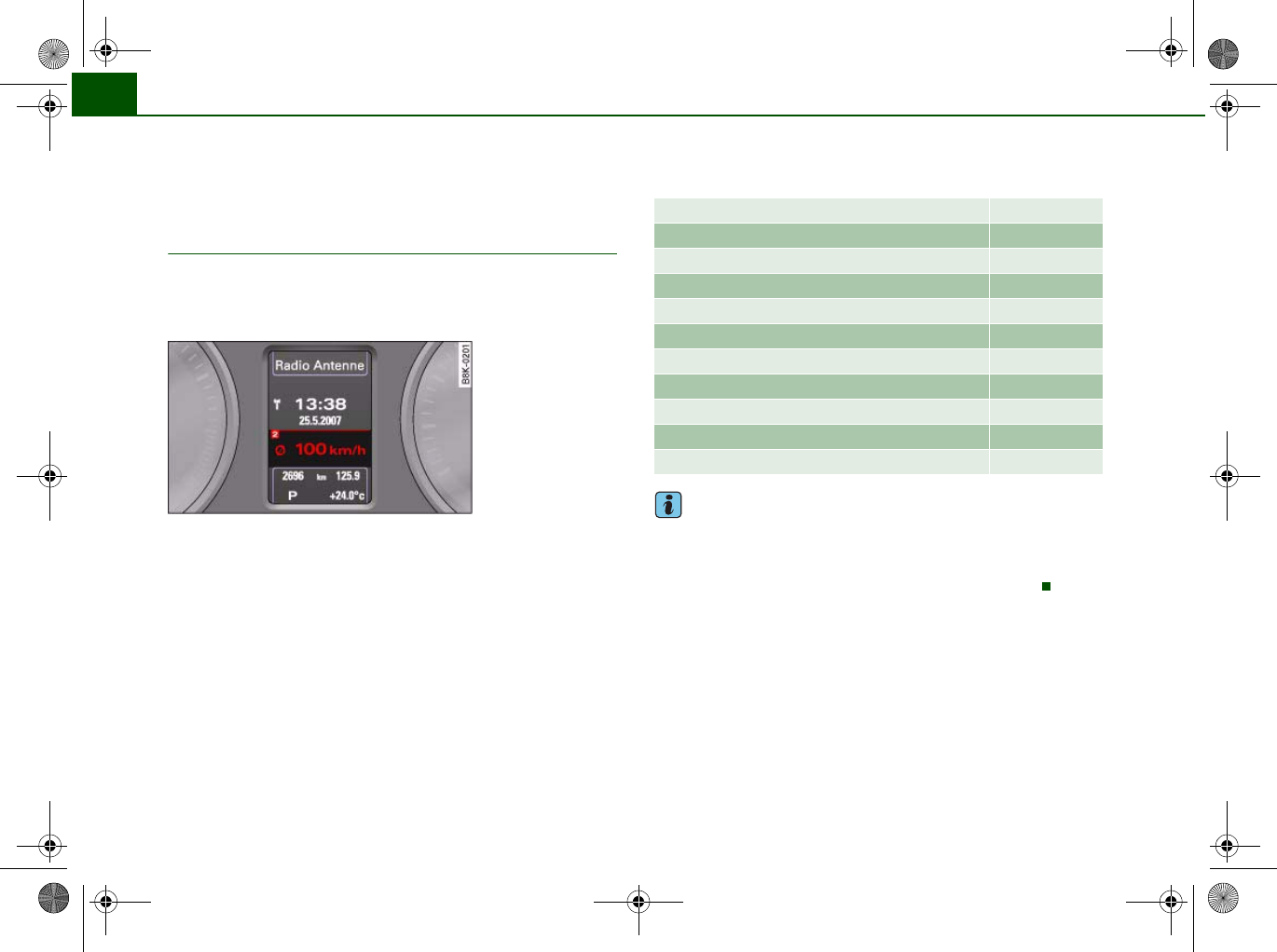
CD and radio display
If no priority 1 or 2 faults have been detected by the auto-check
control, the name or frequency of the current radio station and the
selected waveband will appear the upper part of the display.
When a CD is playing, the display will show the current title. If the
vehicle is equipped with a CD changer* the display will also show
the number of the CD being played (CD1 to CD6).
Outside temperature display
The outside temperature is shown when the display is
activated.
At temperatures below +5°C a snowflake symbol appears next to the
temperature display. This is to warn the driver to take extra care
when there is a risk of ice on the road.
When the vehicle is stationary or travelling at very low speeds, the
temperature displayed may be slightly higher than the actual
outside temperature as a result of the heat radiated from the
engine.
The temperature units can be set to °F or °C on the MMI* or sound
system control console. The outside temperature is automatically
displayed in the units you have selected. Please refer to the Oper-
ating Manual for the MMI* or sound system.
WARNING
Do not rely on the outside temperature display as an ice warning.
Please bear in mind that there may be patches of ice on the roads
even at outside temperatures around +5°C.
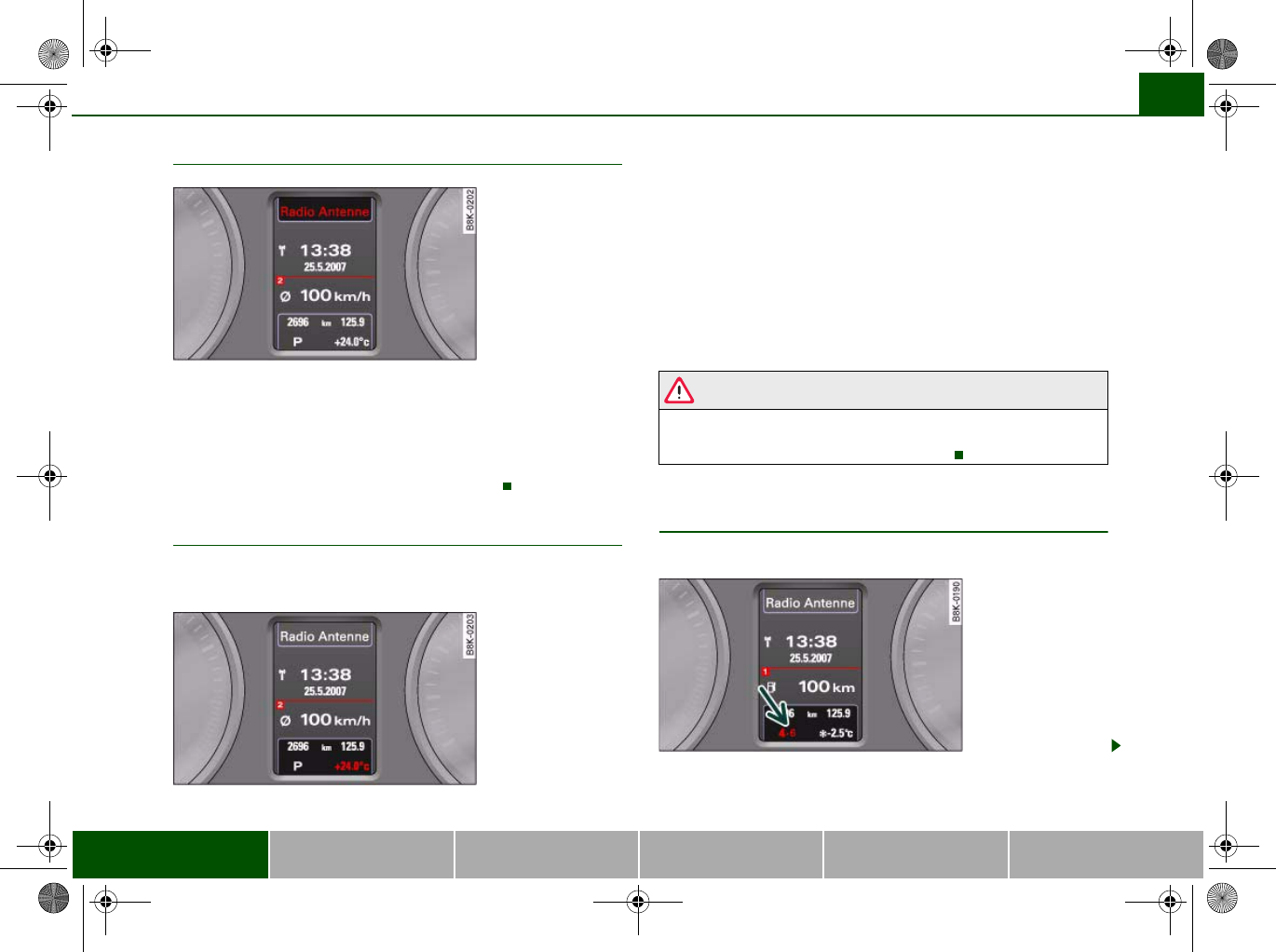
Applies to vehicles: with manual gearbox and gear-change indicator
Gear-change indicator
This additional indicator function can help to save fuel.
Fig. 9 Display: Radio
information
Fig. 10 Display:
Outside temperature
Fig. 11 Display: Gear-
change indicator
document_0900452a8179700c.book Seite 21 Donnerstag, 22. März 2007 10:19 10
Driver information system22
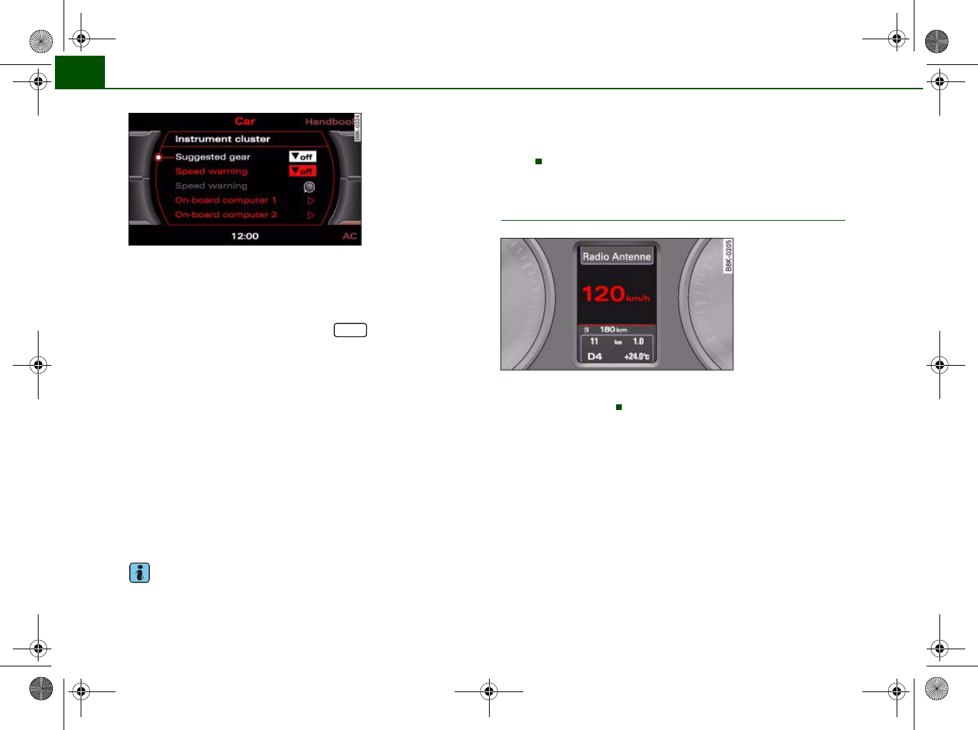
You can deactivate the gear-change indicator on the sound
system or MMI.
Switching the gear-change indicator on and off
– Select: Function selector button > Instrument
cluster > Suggested gear ⇒fig. 12.
To familiarise yourself with the gear-change indicator, we recom-
mend driving in the normal way to start with. A gear change will be
recommended if the gear you are in is not the most economical
choice for the current driving conditions. The gear you are currently
in and the recommended gear will be displayed ⇒page 21, fig. 11.
•Shifting up a gear: The suggested gear appears to the right of the
current gear when a higher gear is recommended.
•Shifting down a gear: The suggested gear appears to the left of
the current gear when a lower gear is recommended.
Gears may ocassionally be skipped (3 > 5).
If no gear change is recommended, you are already in the most
economical gear.
Note
•The gear-change indicator is intended to help save fuel. It is not
intended to recommend the right gear for all driving situations. For
example, the display may not recommend a gear change while you
are overtaking, driving up a steep gradient or towing a trailer.
•The gear-change indicator goes out when you press the clutch
pedal.
Applies to vehicles: with on-board computer
Digital speedometer
The display shows the current speed. The speed is displayed in
increments of 1 km/h.
Fig. 12 MMI display:
Switching the
suggested gear on and
off
CAR
Fig. 13 Display: Digital
speedometer
document_0900452a8179700c.book Seite 22 Donnerstag, 22. März 2007 10:19 10
Driver information system 23
Controls Safety Driving tips General maintenance Self-help Technical data
Door catches / boot lid warning
The pictogram shows whether the doors and the boot lid,
etc. are properly closed when driving off.
The door catches/boot lid warning symbol lights up if one or more
of the doors, or the bonnet or boot lid are not properly closed when
the ignition is on. The symbol also indicates which of these is not
properly closed ⇒fig. 14.
The warning symbol disappears when all the doors, the bonnet and
the boot lid are completely closed, and the driver information func-
tions selected will then be displayed again.
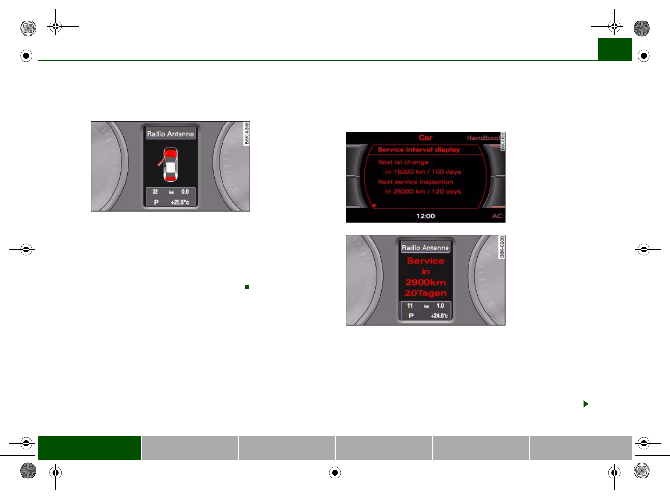
Service interval display
This display reminds the driver when the next routine
service is due and is called up using the MMI or the sound
system control console.
The date when the next service is due is calculated automat-
ically and the driver is reminded accordingly.
Service reminder
– When the next service date is approaching, SERVICE IN -
---- KM --- DAYS ⇒fig. 16 will be shown in the display
each time you switch on the ignition.
Fig. 14 Display: Door
catches/boot lid
warning Fig. 15 MMI display:
Service interval displa
y
Fig. 16 Instrument
cluster display: Service
interval display
document_0900452a8179700c.book Seite 23 Donnerstag, 22. März 2007 10:19 10
Driver information system24
– The remaining time and distance to the next service are
indicated every time the ignition is switched on, until the
service becomes due.
Service due
–When a service is due, Service! will appear in the display
as soon as you switch on the ignition. The display reverts
back to the standard display after about 5 seconds.
Displaying the service interval
– Select: Function selector button > Service interval
display ⇒page 23, fig. 15.
Resetting the oil change interval display
– Select: Function selector button > Service interval
display > Reset oil change interval.
Displaying distance to next service
You can have the distance to the next service displayed on the MMI
screen ⇒page 23, fig. 15. The remaining distance to the next
service is updated every time the ignition is switched on (starting at
500 km after a service has been performed).
On a new vehicle, the display will always show the following
message for the first 500 km.
SERVICE IN ----- KM --- DAYS
Caution
The system cannot calculate the figures for the service indicator if
the battery is disconnected from the vehicle, so no service reminder
can be displayed during this time. Please remember that keeping to
the correct service intervals is most important for the service life
and residual value of the vehicle (and especially for the life of the
engine). The period between two services must never be longer
than the time specified in the Service Schedule, even if you only
cover a low mileage during this time.
Note
•Do not reset the display between oil changes - otherwise the
display will be incorrect.
•The information in the service interval display remains intact if
the battery is disconnected.
•The distance to the next service cannot be called up if the system
has detected a Priority 1 fault (red symbol).
•If the service was not performed by a qualified workshop, the oil
change interval display can only be set to “fixed service intervals” of
15,000 km. If you wish to continue with the “LongLife” service, you
will need to have the oil change interval display reset by a qualified
workshop.
CAR
CAR
document_0900452a8179700c.book Seite 24 Donnerstag, 22. März 2007 10:19 10
Driver information system 25
Controls Safety Driving tips General maintenance Self-help Technical data
On-board computer
Applies to vehicles: with on-board computer
Introduction
The on-board computer provides you with useful informa-
tion during a journey, including average and current fuel
consumption, average speed, fuel range and driving time.
The following items of information are processed by the on-board
computer and can be shown one after the other on the display in the
instrument cluster.
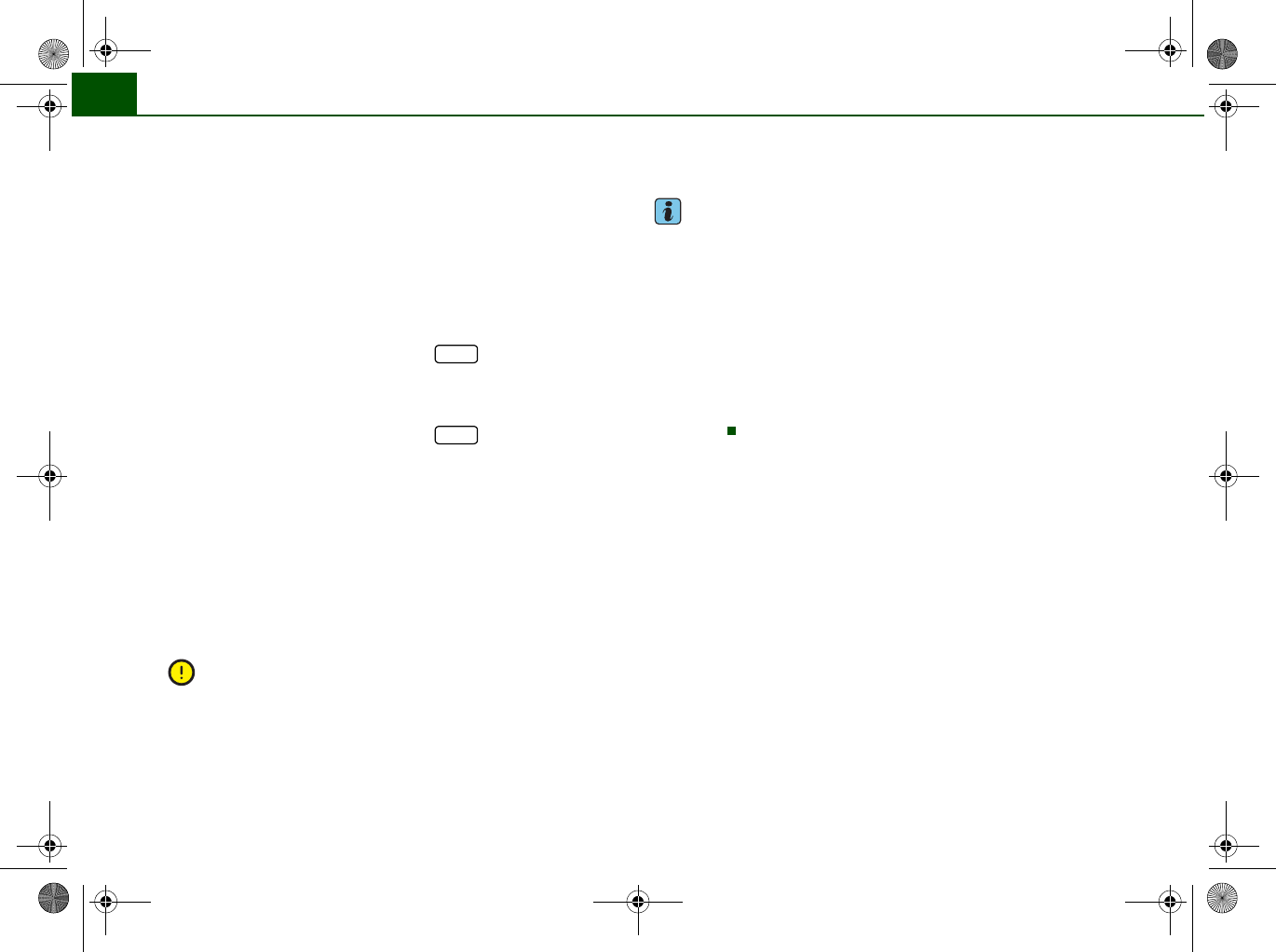
Fuel range
The estimated fuel range is displayed in km. It shows how far the
vehicle can be driven with the amount of fuel left in the tank,
assuming the same style of driving. The fuel range is displayed in
increments of 10 km.
The fuel range is calculated on the basis of the fuel consumption
over the last 30 kilometres. The fuel range will increase accordingly
if you drive in a more economical manner.
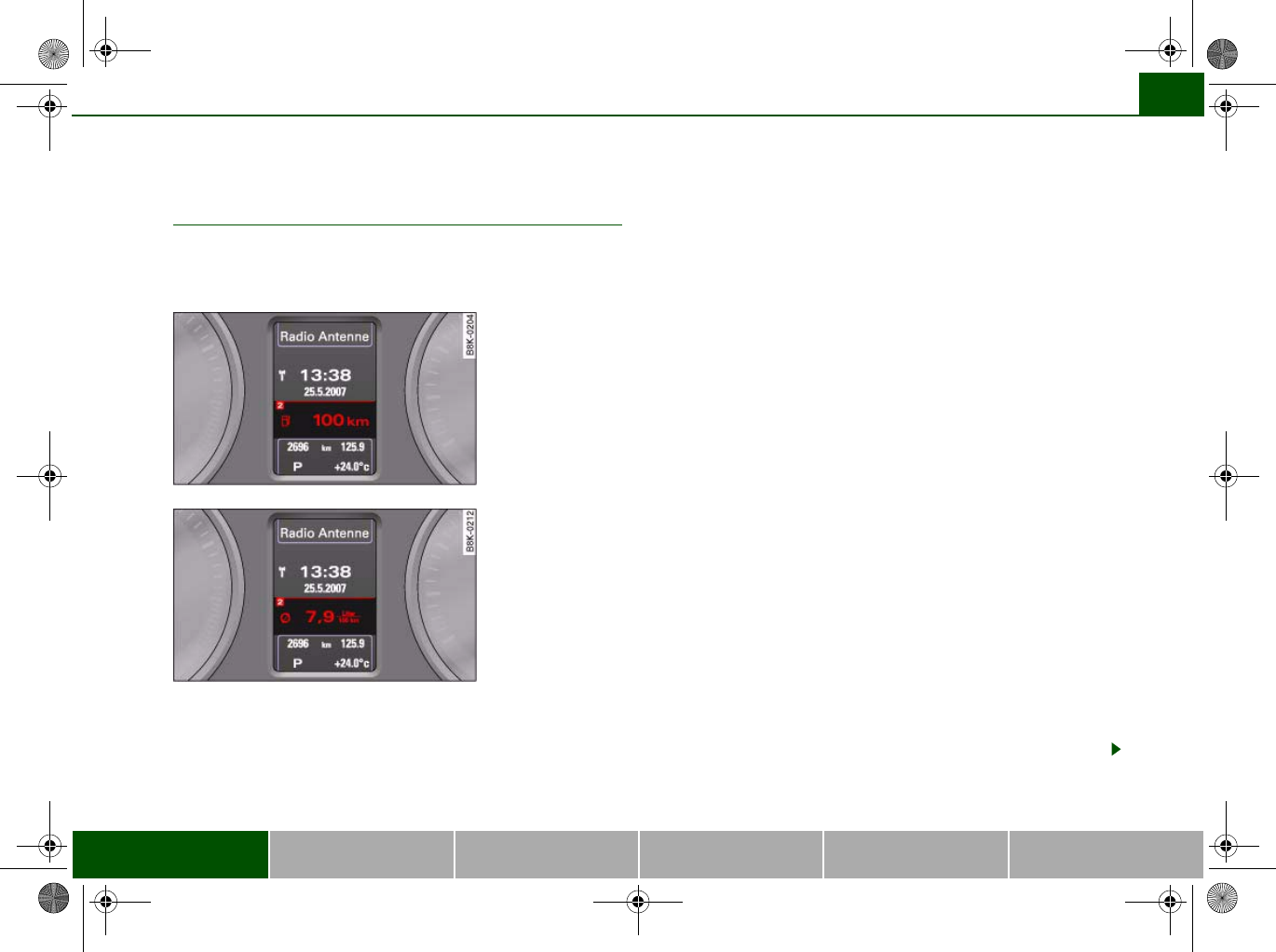
Average fuel consumption
This mode displays the average fuel consumption since the memory
was last cancelled in litres/100 km. If required, you can use this
display to adjust your driving style to achieve the desired fuel
consumption.
Current fuel consumption
The display shows the current fuel consumption in litres/100 km. If
required, you can use this display to adjust your driving style to
achieve the desired fuel consumption.
The computer calculates the fuel consumption every 30 metres. The
display switches to l/h (litres per hour) when the vehicle is
stationary.
Average speed
This mode shows the average speed driven since the memory was
last cancelled (in km/h).
Driving time
This display shows the period of time which has elapsed since the
memory was last cancelled.
Distance covered
This display shows the distance you have covered since the memory
was last cancelled.
Fig. 17 On-board
computer: Fuel range
Fig. 18 On-board
computer: Average fuel
consumption
document_0900452a8179700c.book Seite 25 Donnerstag, 22. März 2007 10:19 10
Driver information system26
Note
•The displays for fuel consumption (average and current
consumption), fuel range and speed are shown in metric units. You
can change the measurement units on the MMI display.
•The information in the memory is cancelled if the battery is
disconnected.
Applies to vehicles: with on-board computer
Memory
The on-board computer has two automatic journey
memories.
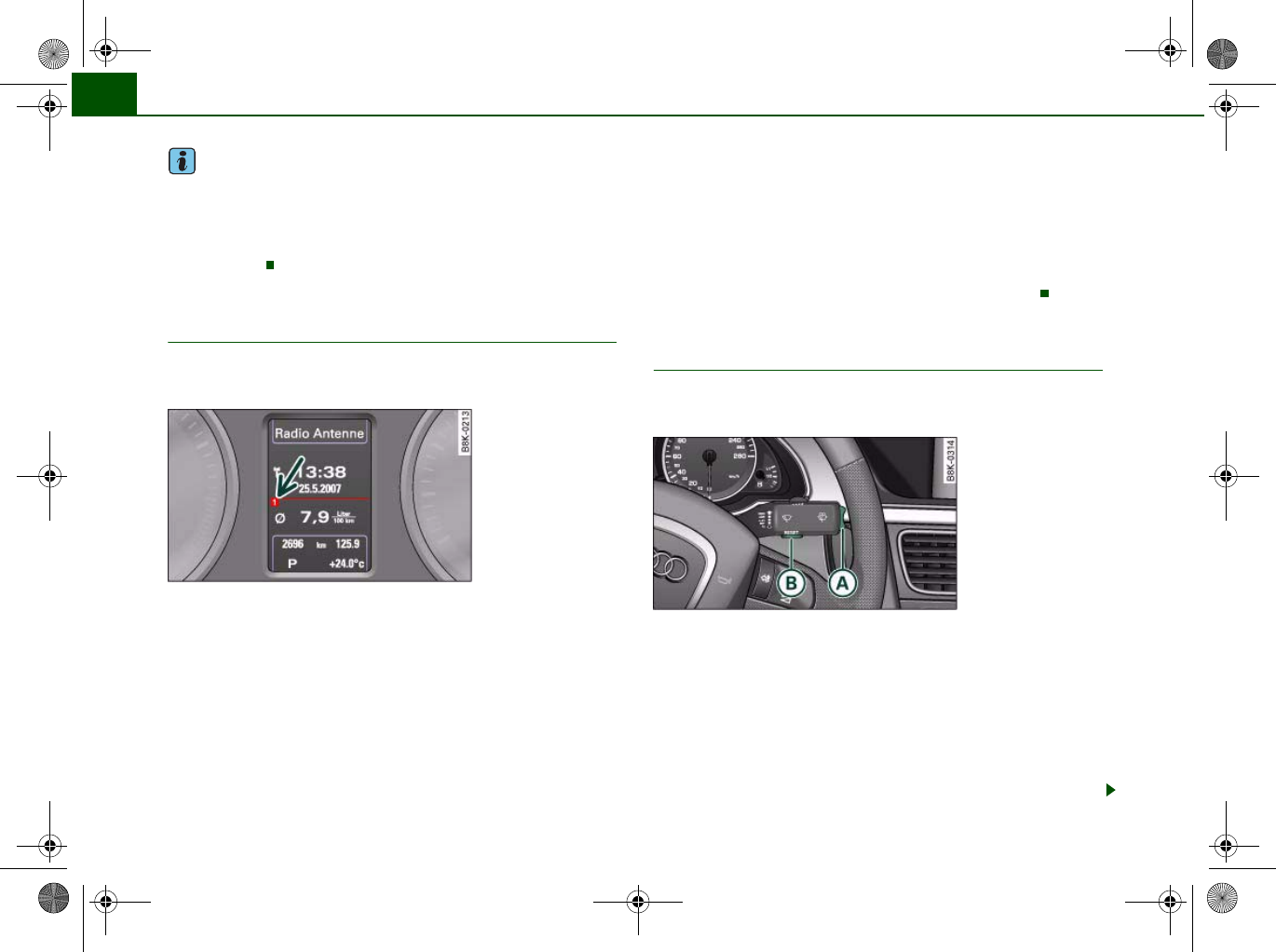
Press RESET button ⇒fig. 20 to switch back and forward
between the functions of on-board computers 1 and 2.
The number in the display ⇒fig. 19 indicates which of the two
memories is currently in use. The figure 1 means that the display is
showing the information in the single journey memory (on-board
computer 1). The figure 2 means that the display is showing the
information in the total journey memory (on-board computer 2).
Single journey memory (on-board computer 1)
The single journey memory processes the information on a journey
from the time the ignition is switched on until it is switched off. If
the journey is resumed within two hours after the ignition is
switched off, the new figures are automatically included in the
calculation. The memory is automatically deleted when you resume
driving, if the journey is interrupted for more than two hours.
Total journey memory (on-board computer 2)
Unlike the single journey memory, the total journey memory is not
erased automatically. In this way, you can determine the period for
which you wish the on-board computer to supply figures.
Applies to vehicles: with on-board computer
Controls
The on-board computer is controlled by means of two
switches on the windscreen wiper lever.
– Press the top or bottom of the function selector switch
⇒fig. 20. This displays the on-board computer read-
outs one after the other.
The on-board computer can only be operated while the ignition is
switched on. When the ignition is switched on, the display shows
the function that was last selected.
As well as the figures from the on-board computer (computer 1 or
2), the display can also show information from the digital speedom-
Fig. 19 On-board
computer: Memory 1
A
B
Fig. 20 Windscreen
wiper lever: On-board
computer controls
A
A
document_0900452a8179700c.book Seite 26 Donnerstag, 22. März 2007 10:19 10
Driver information system 27
Controls Safety Driving tips General maintenance Self-help Technical data
eter and navigation system*. Press the Reset button briefly to
switch back and forward between these displays.
Resetting figures to zero
To cancel one of the computer readings individually, select the
required function and press the RESET button for at least one
second. The following values can be reset to zero individually using
the Reset button:
•Average fuel consumption
•Average speed
•Driving time
•Distance covered
You can also cancel all the values in the single journey memory or
the total journey memory at the same time ⇒page 27.
Note
The information in the memory is cancelled if the battery is
disconnected.
Applies to vehicles: with on-board computer
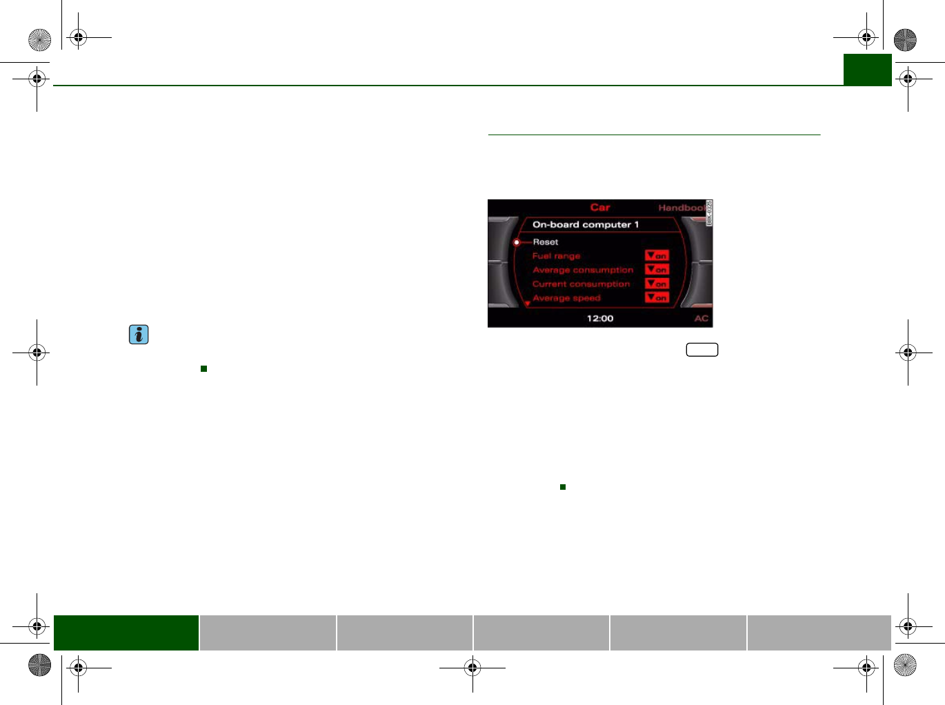
Basic settings for the on-board computer
You can change the basic settings for the on-board
computer on the MMI* or on the sound system control
console.
– Select: Function selector button > Instrument
cluster > On-board computer 1 or On-board computer 2.
You can zero all the values in the single journey memory or the total
journey memory at the same time by selecting the Reset menu item.
You can also define which items of information you wish to have
displayed by the on-board computer. If one of these items is
switched off, it will not appear in the display. However, the corre-
sponding figures will still be registered by the on-board computer
and can be switched back on at any time so that they again appear
in the display.
A
B
A
B
Fig. 21 MMI display:
On-board computer
CAR
document_0900452a8179700c.book Seite 27 Donnerstag, 22. März 2007 10:19 10
Driver information system28
Speed warning function
Applies to vehicles: with speed warning function
Introduction
The speed warning function can help you keep below a
pre-set maximum speed.
The speed warning function will warn you if the vehicle exceeds the
pre-set maximum speed. The system gives an audible warning
signal if the set speed is exceeded by about 3 km/h. A warning
symbol will also appear in the display . On some models the symbol
may look slightly different.
The speed warning function has two different warning speeds,
which operate independently and serve slightly different purposes:
Speed limit warning 1
With speed limit warning 1, the maximum speed can be changed
while driving. The speed limit that has been set remains stored until
the ignition is switched off, or until it is changed or cleared.
The speed limit warning symbol for speed limit warning 1 will
appear in the display if you exceed the pre-set speed. It goes out
again if the speed is reduced below the set speed limit.
The symbol also goes out if the speed is increased to more than
about 40 km/h above the set speed for at least 10 seconds. This
cancels the speed limit that was originally set.
Setting speed limit warning 1 ⇒page 28.
Speed limit warning 2
You are recommended to store this speed limit warning if you
always wish to be reminded of a particular speed limit. This could
be when driving in countries with general speed limits, or if you
need to keep below a particular speed when winter tyres are fitted,
etc.
The speed limit warning symbol for speed warning 2 will appear
in the display if you exceed the pre-set speed. Unlike speed limit
warning 1, the warning symbol only goes out once the road speed
has dropped below the stored value again.
Setting speed limit warning 2 ⇒page 29.
Note
Please bear in mind that, even with the speed warning function, it is
still important to keep a check on the car's speed with the speedom-
eter and to observe the statutory speed limits.
Applies to vehicles: with speed warning function
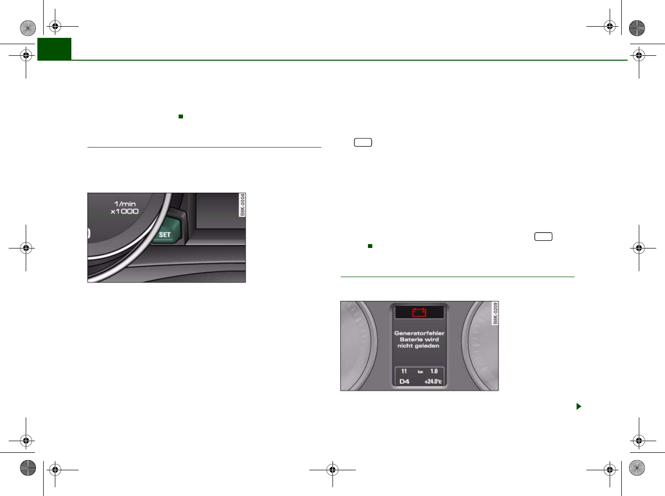
Setting speed limit warning 1
You can use the button to set, alter or cancel speed
limit warning 1.
Selecting speed limit
– Drive at the desired maximum speed.
– Press the button in the instrument cluster ⇒fig. 22
for one second.
SET
Fig. 22 Detail of the
instrument cluster:
SET button
SET
document_0900452a8179700c.book Seite 28 Donnerstag, 22. März 2007 10:19 10
Driver information system 29
Controls Safety Driving tips General maintenance Self-help Technical data
Clearing speed limit
– Drive the vehicle at a minimum of 5 km/h.
– Press the button for at least 2 seconds.
The speed warning symbol lights up briefly in the display to
confirm that the selected speed has been stored. The speed limit
that has been set remains stored until another speed is set with a
brief push of the button, or until the memory is cleared with a long
push of the button.
When the speed limit has been cleared, the display will show a
crossed-out warning symbol .
Applies to vehicles: with speed warning function
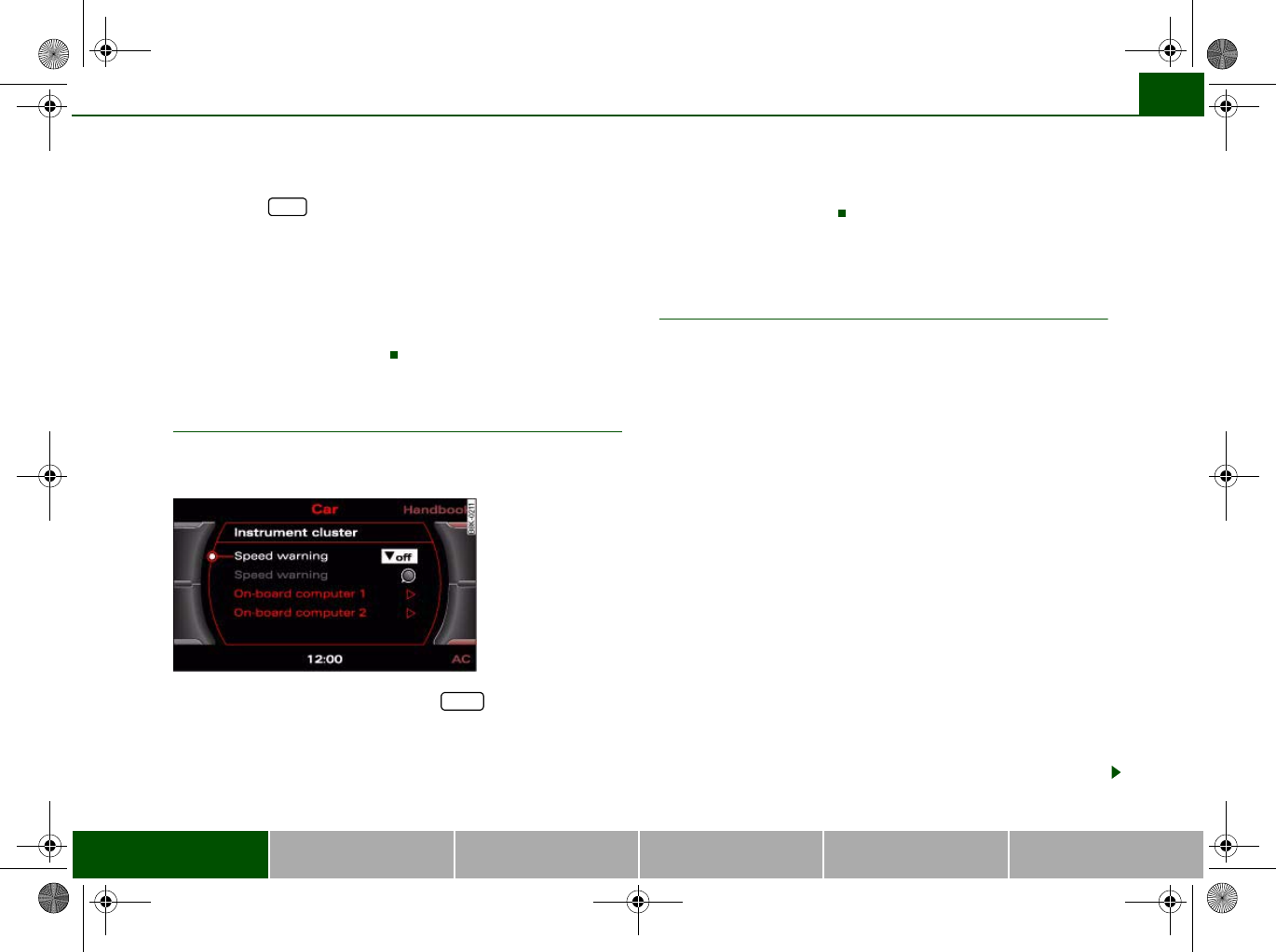
Setting speed limit warning 2
You can use the MMI* or sound system control console to
set, alter or cancel speed limit warning 2.
– Select: Function selector button > Instrument
cluster > Speed warning.
•Speed warning on/off - to activate or deactivate the speed
warning function ⇒fig. 23.
•Speed warning - to set the speed above which a warning signal
will sound.
Speed limit warning 2 can be adjusted in increments of 10 km/h
between 30 and 240 km/h.
Auto-check control
Introduction
The auto-check control checks important components and vehicle
systems. These background checks are run constantly, as long as
the ignition is switched on.
A message is displayed in the instrument cluster if a fault should
occur or if any maintenance or repairs are urgently required. This is
accompanied by an audible warning signal. Depending on the
priority of the fault, a red or yellow warning symbol lights up in the
display.
The red symbols indicate a serious malfunction, whereas the yellow
ones represent other malfunctions or items requiring attention.
Additional messages to assist the driver may be shown with the red
or yellow symbols.
Automatic gearbox* function test
The auto-check control automatically checks the vehicle systems
when the ignition is switched on. If the selector lever is in position
P or N, the following instruction will appear:
When stationary apply footbrake while selecting gear
When a gear (R, D etc.) is selected, this message disappears and the
auto-check control function is displayed.
The driver message will disappear 30 seconds after switching on
the ignition or earlier, if there are other driver messages or malfunc-
tions.
SET
Fig. 23 MMI display:
Setting speed limit
warning 2
CAR
document_0900452a8179700c.book Seite 29 Donnerstag, 22. März 2007 10:19 10
Driver information system30
If one or more faults are detected, the driver information message
(as above) will disappear about 15 seconds after the engine has
been started and the appropriate fault symbol(s) will appear in the
display. The warning display will be accompanied by the corre-
sponding warning chime.
Driver messages
Additional messages to assist the driver are displayed
together with the warning symbols in the instrument
cluster.
For example, the following driver message will appear if the selector
lever for the automatic gearbox* is not in position P when you
switch off the engine:
Shift to P, otherwise vehicle can roll away. Doors do not lock if
lever is not in P
The ignition key can only be withdrawn when the selector lever is in
this position. Similar messages will be displayed if other functions
of this kind cannot be carried out.
Driver messages and red symbols
If a red warning symbol appears in the display, it will automatically
be accompanied by the corresponding driver message.
For example, in the event of an oil pressure malfunction the oil pres-
sure symbol will appear in the display. In addition, the following
message will appear:
Switch off engine and check oil level
The message will disappear from the display after about 5 seconds.
If required, the message can be called up again by briefly pressing
the button ⇒fig. 24.
Driver messages and yellow symbols
If a yellow warning symbol appears in the display, it will automati-
cally be accompanied by the corresponding driver message.
For example, if the symbol appears (windscreen washer fluid
low), the display will also show the message:
Please top up washer fluid
The message will disappear after a few seconds. If required, the
message can be called up again by briefly pressing the
button.
Red symbols
A red symbol warns of a serious malfunction.
–Stop the vehicle.
Fig. 24 Instrument
cluster: SET button
SET
SET
Fig. 25 Display:
Symbol for serious
malfunction
document_0900452a8179700c.book Seite 30 Donnerstag, 22. März 2007 10:19 10
Driver information system 31
Controls Safety Driving tips General maintenance Self-help Technical data
– Switch off the engine.
– Check the function displayed. Obtain professional assist-
ance if necessary.
The red symbols indicate a Priority 1 fault (serious malfunction).
Should a Priority 1 fault occur, a red warning symbol will appear at
the top of the display ⇒page 30, fig. 25. The symbol is accompa-
nied by a driver message giving you more information about the
fault. This symbol is accompanied by three warning chimes. The
symbol will keep flashing until the fault is corrected.
If several Priority 1 faults are detected at the same time, the symbols
are displayed one after the other for about 2 seconds at a time.
This message will disappear after about 5 seconds, but you can call
it up again at any time by pressing the button ⇒page 30.
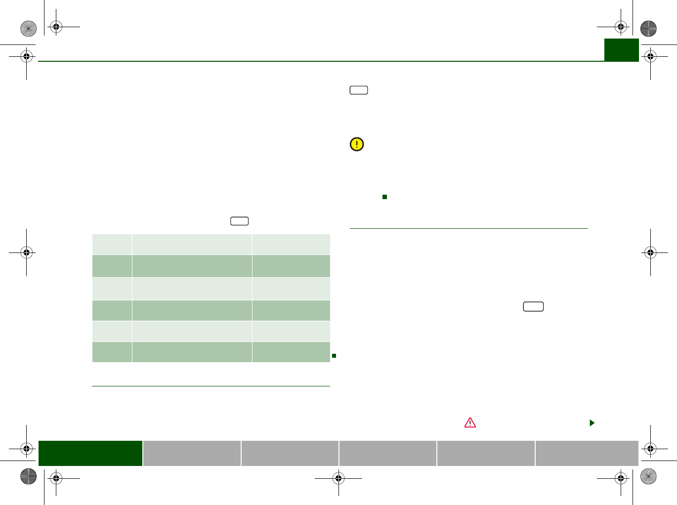
Alternator fault
If the symbol flashes in the instrument cluster display, there is an
alternator fault or a fault in the vehicle's electrical system. In addi-
tion, a message will appear. This message will disappear after about
5 seconds, but you can call it up again at any time by pressing the
button.
You should normally be able to drive to the next available qualified
workshop. However, you should avoid using electrical equipment
that is not absolutely necessary because this will drain the battery.
Caution
If the coolant warning lamp in the instrument display lights up
as well as the alternator warning lamp while driving ⇒page 32, stop
the vehicle immediately and switch off the engine. In this case the
coolant pump is no longer being driven, and there is a risk of engine
damage.
Fault in the brake system
A fault in the brake system should be corrected as soon as
possible.
If the symbol flashes in the display, there is a fault in the
brake system. The symbol is accompanied by a driver
message giving you more information about the fault. This
message will disappear after about 5 seconds, but you can
call it up again at any time by pressing the button:
Stop vehicle and check brake fluid level
– Stop the vehicle.
– Check the brake fluid level ⇒page 238.
– Obtain professional assistance if necessary.
Warning! Fault in ABS brake system. Contact
workshop
– Drive carefully to the nearest qualified workshop and
have the fault rectified ⇒.
Alternator fault ⇒page 31
Fault in brake system/ parking
brake
⇒page 31
Coolant level too low / coolant
temperature too high
⇒page 32
Engine oil pressure too low ⇒page 33
Fault in the steering system ⇒page 33
Ignition lock defective ⇒page 34
SET
SET
SET
document_0900452a8179700c.book Seite 31 Donnerstag, 22. März 2007 10:19 10
Driver information system32
Parking brake ! Please contact workshop
– If the symbol appears after you switch on the ignition
when the vehicle is stationary, please check whether you
can release the parking brake. If this is possible, you
should drive without delay to the nearest qualified work-
shop and have the fault rectified. If the parking brake
cannot be released you should obtain professional
assistance.
– If this symbol should appear while driving, there may be
a malfunction in the drive-away assist or the emergency
brake functions. You may not be able to apply the parking
brake. It is also possible that you cannot release the
parking brake after it has been applied. Drive the vehicle
to a qualified workshop and have the fault repaired.
If the ABS fails, the ABS warning lamp will light up together with
the brake warning symbol ⇒.
WARNING
•Before opening the bonnet and checking the brake fluid level,
observe the warning information on ⇒page 231, “Working on
components in the engine compartment”.
•If the brake fluid level in the reservoir is too low, this could
result in an accident. Do not drive on. You should obtain profes-
sional assistance.
•If the brake warning lamp lights up together with the ABS
warning lamp, this can mean that the control function of the ABS
is out of action. As a result the rear wheels can lock relatively
easily when braking. This could cause the tail of the vehicle to skid
sideways. Drive carefully to the nearest qualified workshop and
have the fault rectified.
Note
The warning lamp in the instrument cluster will start flashing as
well if there is a fault in the brake system.
Fault in the cooling system
Faults in the cooling system must be rectified immedi-
ately.
If the symbol flashes in the display, this means that
either the coolant temperature is too high or the coolant
level is too low. The symbol is accompanied by a driver
message giving you more information about the fault. This
message will disappear after about 5 seconds, but you can
call it up again at any time by pressing the button:
Switch off engine, check coolant level
–Stop the vehicle.
– Switch off the engine.
– Check the coolant level ⇒page 236.
– Add more coolant if necessary ⇒page 236.
– Wait for the symbol to go out before driving on.
– Obtain professional assistance if necessary.
If the coolant level is correct, the overheating may be caused by a
malfunction of the radiator fan.
If the alternator warning lamp lights up as well ⇒page 31, it is
possible that the drive belt has broken.
SET
document_0900452a8179700c.book Seite 32 Donnerstag, 22. März 2007 10:19 10
Driver information system 33
Controls Safety Driving tips General maintenance Self-help Technical data
WARNING
•If your vehicle should break down for technical reasons, stop it
at a safe distance away from moving traffic, switch off the engine
and turn on the hazard warning lights ⇒page 58, “Hazard
warning lights ”.
•Never open the bonnet if you can see or hear steam or coolant
escaping from the engine compartment; there is a risk of being
scalded. Wait until you can no longer see or hear escaping steam
or coolant.
•The engine compartment of any motor vehicle is a dangerous
place. Before carrying out any work in the engine compartment,
switch off the engine and allow it to cool down. Please observe the
important safety warnings ⇒page 231, “Working on components
in the engine compartment”.
Caution
Do not drive on if the symbol has come on to indicate a fault in
the cooling system, otherwise there is a risk of damaging the
engine.
Engine oil pressure too low
If the engine oil pressure is too low the fault must be recti-
fied immediately.
If the symbol flashes in the display, the oil pressure is
too low. The symbol is accompanied by a driver message
giving you more information about the fault. This message
will disappear after about 5 seconds, but you can call it up
again at any time by pressing the button:
Switch off engine and check oil level
–Stop the vehicle.
– Switch off the engine.
– Check the engine oil level ⇒page 234.
– Obtain professional assistance if necessary.
If the engine oil level is too low
If the engine oil level is too low, add more oil ⇒page 234.
If the engine oil level is correct
If the symbol flashes and the engine oil level is correct, obtain
professional assistance. Do not drive on. Do not continue to run the
engine, not even at idle speed.
Note
The oil pressure warning lamp is not an indicator for the oil
level. The oil level should therefore be checked regularly.
Fault in the steering system
The steering wheel cannot be unlocked if there is a fault
in the electronic steering lock.
If the symbol flashes in the display, there is a malfunc-
tion in the electronic steering lock. The symbol is accompa-
nied by a driver message giving you more information
about the fault. This message will disappear after about
5 seconds, but you can call it up again at any time by
pressing the button:
Do not drive vehicle. Steering defective
– You should obtain professional assistance.
–Do not have the vehicle towed away.
SET
SET
document_0900452a8179700c.book Seite 33 Donnerstag, 22. März 2007 10:19 10
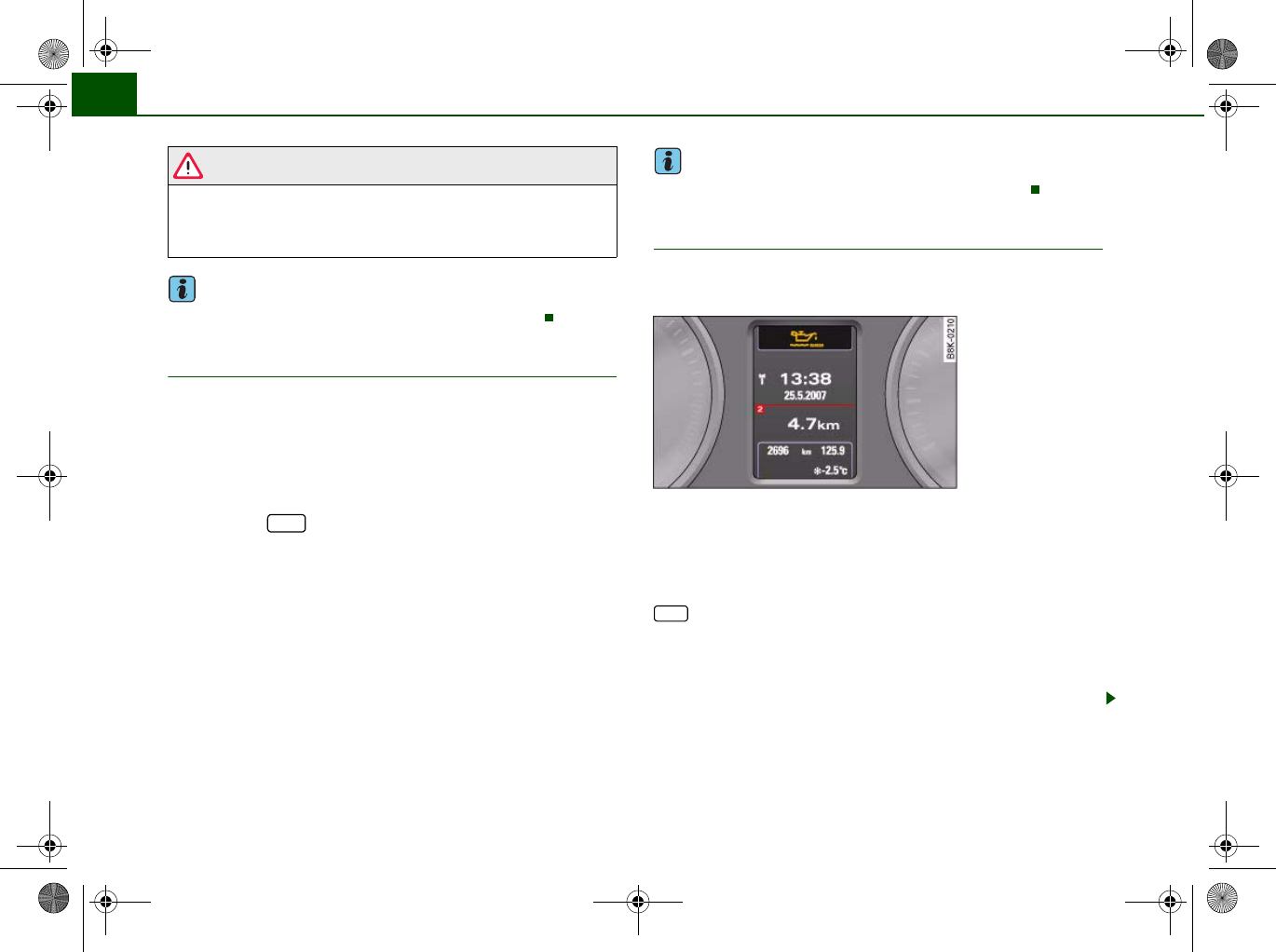
Driver information system34
WARNING
The vehicle must not be towed if there is a fault in the electronic
steering lock: the steering will be locked and the vehicle cannot be
steered. Towing a vehicle with locked steering can cause an acci-
dent.
Note
On some models the symbol may look slightly different.
Ignition lock defective
A fault in the ignition lock must be rectified immediately.
If the symbol flashes in the display, there is a malfunc-
tion in the electronic ignition lock. The symbol is accompa-
nied by a driver message giving you more information
about the fault. This message will disappear after about
5 seconds, but you can call it up again at any time by
pressing the button:
Ignition lock defective. Contact workshop!
–Do not switch off the engine.
– Drive the vehicle without delay to a qualified workshop
and have the fault repaired.
The ignition cannot be switched off if there is a fault in the elec-
tronic ignition lock. For this reason, you should drive the vehicle
without delay to a qualified workshop and have the cause of the
fault repaired.
If the vehicle is equipped with the advanced key* feature, you
should not switch off the engine with the Stop/Start button because
it cannot be started again after the ignition has been switched off.
Note
On some models the symbol may look slightly different.
Yellow symbols
A yellow symbol indicates a malfunction or other item
requiring attention.
Yellow symbols indicate a Priority 2 fault.
Yellow symbols are accompanied by one warning chime. The
symbol is accompanied by a driver message giving you more infor-
mation about the fault. This message will disappear after about
5 seconds, but you can call it up again at any time by pressing the
button.
The function indicated should be checked as soon as possible. The
yellow symbol will only go out when the fault has been rectified.
If several Priority 2 faults are detected at the same time, the symbols
are displayed one after the other for about 2 seconds at a time.
SET
Fig. 26 Display: Yellow
warning symbol
SET
document_0900452a8179700c.book Seite 34 Donnerstag, 22. März 2007 10:19 10
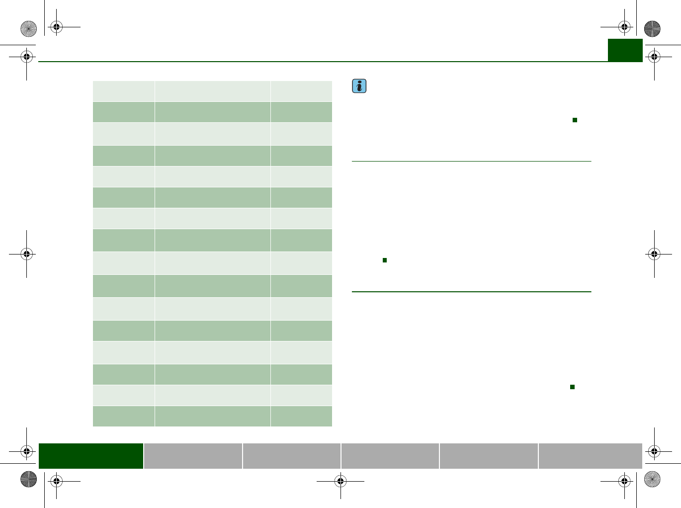
Driver information system 35
Controls Safety Driving tips General maintenance Self-help Technical data
Note
On some models the speed limit warning 1 and speed limit
warning 2 will also be displayed as yellow symbols. These always
appear as a small symbol at the top of the display ⇒page 28.
Applies to vehicles: with advanced key
Key not in vehicle
Key not in vehicle
This message will appear together with the symbol if the remote
control key is removed from the vehicle while the engine is running.
This is to remind you not to continue driving without the key (for
example if you change drivers).
If the remote control key is not in the vehicle you will not be able to
switch on the ignition or restart the engine after it has been
switched off. You will also not be able to lock the vehicle from the
outside.
Light sensor/ rain sensor defective
Automatic headlights/ automatic wipers defective
If the symbol appears, this means that the light sensor/ rain
sensor is not functioning. For safety reasons, the dipped beam
headlights will then be switched on permanently when the light
switch is set to the AUTO position. However, you can still switch the
lights on and off in the normal way with the light switch. If the rain
sensor is defective, the functions operated via the windscreen wiper
lever will still be available. You should have the light sensor/ rain
sensor checked by a qualified workshop as soon as possible.
Brake pads worn ⇒page 36
Battery power* ⇒page 36
Bulb monitor*
Bulb failure*
⇒page 36
Check engine oil level ⇒page 37
Engine oil sensor defective ⇒page 37
Fuel level low ⇒page 36
Washer fluid level low* ⇒page 36
advanced key*
Key not in vehicle
⇒page 35
Light sensor/ rain sensor defec-
tive
⇒page 35
Diesel particulate filter*
obstructed
⇒page 37
Dynamic headlight range con-
trol* defective
⇒page 37
Battery in remote control key ⇒page 40
Electro-mechanical
parking brake
⇒page 123
adaptive light* defective ⇒page 37
Ignition lock defective ⇒page 37
Windscreen wiper defective ⇒page 38
document_0900452a8179700c.book Seite 35 Donnerstag, 22. März 2007 10:19 10
Driver information system36
Brake pads worn
Brake pads!
If the symbol lights up, have the front brake pads (and, for
safety's sake the rear pads as well) inspected by a qualified
workshop.
Applies to vehicles: with bulb monitor
Bulb monitor
The bulb monitor checks whether the lights on the vehicle
are working.
The bulb monitor checks whether the lights on the vehicle are
working. If it detects a defective bulb on the vehicle it will show a
yellow warning symbol together with a message indicating which
light is not working.
Bulb failure
If the symbol lights up, this means that one of the turn signals
(front or rear), headlights, brake lights, rear lights, fog lights or the
rear fog light is not working.
WARNING
•Bulbs are sensitive to pressure. The glass can break when you
touch the bulb, causing injury.
•Incorrect handling of the high-voltage element of xenon gas-
discharge bulbs* can have potentially fatal consequences.
Note
Have the components repaired or replaced by a qualified
workshop.
Applies to vehicles: with washer fluid warning system
Washer fluid level low
Please top up washer fluid
If the symbol lights up, top up the fluid for the windscreen
washer and headlight washer system* ⇒page 242.
Fuel level low
Please refuel
When this symbol comes on for the first time, there are about
8 litres of fuel left in the tank. You should fill up as soon as possible
⇒page 228.
If this warning symbol lights up although the fuel tank is sufficiently
filled, there is a malfunction in the fuel tank system. The display will
also show the driver message Tank system malfunction ! Contact
workshop. Please contact a qualified workshop.
Applies to vehicles: with battery power warning system
Battery power
If battery power drops to a level at which you may encounter prob-
lems when starting the engine, the display will show the symbol
and the driver message Low battery charge: Battery will be charged
while driving.
Please bear in mind that the starting ability of the engine may be
impaired while this message is shown.
Message comes on and goes out again
If the message appears in the display after the ignition is switched
on or while driving, and goes out again after a period of time, the
battery has been charged up again sufficiently while the vehicle was
being driven.
document_0900452a8179700c.book Seite 36 Donnerstag, 22. März 2007 10:19 10
Driver information system 37
Controls Safety Driving tips General maintenance Self-help Technical data
Message comes on and does not go out
If the message appears in the display after the ignition is switched
on or while driving, and does not go out again, the battery is not
being maintained at the proper power level. Starting reliability may
be impaired. You should have the battery checked by a qualified
workshop as soon as possible.
Check engine oil level
Please check oil level
If the symbol lights up, check the engine oil level as soon as
possible ⇒page 234. Top up the oil at the next opportunity
⇒page 234.
Engine oil sensor defective
Oil level ! Sensor defective
If the symbol lights up, take the vehicle to a qualified workshop
and have the oil level sensor checked. Until then it is advisable to
check the oil level every time you fill up with fuel ⇒page 234.
Applies to vehicles: with diesel engine and diesel particulate filter
Diesel particulate filter obstructed
Particle filter. See Owner's Manual
When the symbol lights up you can assist the self-cleaning func-
tion of the filter by driving accordingly. You should drive at a speed
of at least 60 km/h (engine speed about 2,000 rpm) for about
15 minutes in 4th or 5th gear, or with the selector lever in position S
on vehicles with automatic gearbox*. As a result of the increase in
temperature the soot in the filter will be burned off. The symbol will
disappear once the cleaning process has been completed success-
fully.
If the symbol does not go out, please contact a qualified work-
shop and have the fault rectified.
For further information on the diesel particulate filter ⇒page 205.
WARNING
It is essential that you adjust your speed to suit the weather, road,
terrain and traffic conditions. The recommended driving speed
must never lead to the driver disregarding the traffic regulations.
Applies to vehicles: with dynamic headlight range control
Headlight range control defective
Headlight range control defective
This symbol indicates a malfunction in the dynamic headlight
range control. Take the vehicle to a qualified workshop to have the
dynamic headlight range control function repaired.
Applies to vehicles: with adaptive light
adaptive light defective
adaptive light defective
This symbol indicates that the adaptive light is defective. Take
the vehicle to a qualified workshop to have the headlights and/or
the control unit for the adaptive light repaired.
Ignition lock defective
Ignition lock defective
If the symbol lights up in the display, there is a malfunction in
the electronic ignition lock. Take the vehicle to a qualified workshop
to have the problem remedied.
document_0900452a8179700c.book Seite 37 Donnerstag, 22. März 2007 10:19 10
Driver information system38
Windscreen wipers defective
Windscreen wipers defective
This symbol indicates a malfunction in the electronics for the
windscreen wipers. Take the vehicle to a qualified workshop to have
the windscreen wiper system repaired.
document_0900452a8179700c.book Seite 38 Donnerstag, 22. März 2007 10:19 10
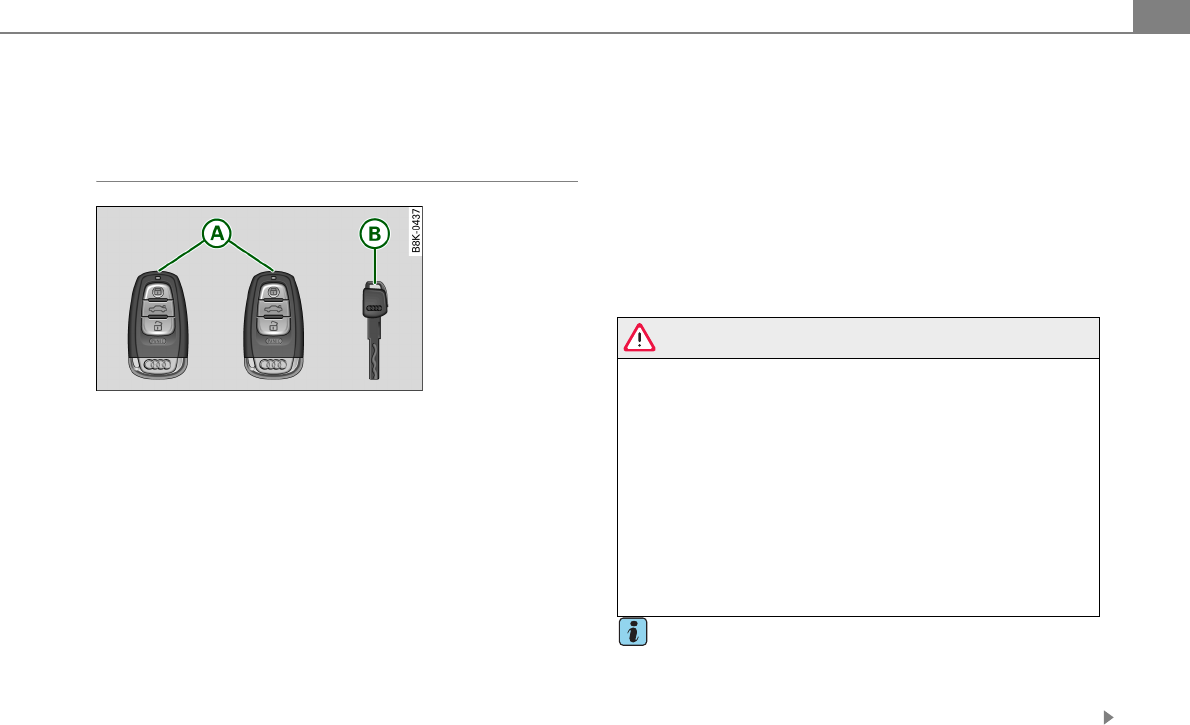
Opening and closing 1
Opening and closing
Keys
Key set
Master key with remote control
You can centrally lock and unlock your vehicle and start the engine
with the master key with remote control.
Emergency key
The emergency key is not intended for constant use. It should only
be used in an emergency. Keep it in a safe place and do not carry it
on your key ring.
Key replacement
If you lose a key, contact your authorized Audi dealer immediately
to have the lost key disabled. Be sure to bring all your keys with you.
Personal comfort settings
If two people use one vehicle, it is recommended that each person
always uses “their own” master key. When the ignition is turned off
or when the vehicle is locked, personal convenience settings for the
following systems are stored and assigned to the remote master
key.
•Climate control
•Central locking system
•Ambient lighting
•Windows
•Audi parking system*
•Seat memory*
The stored settings are automatically recalled when you unlock the
vehicle, when you open the doors or when you turn on the ignition.
WARNING
•Do not leave your vehicle unattended with the key in the igni-
tion lock. Entry by unauthorized persons could endanger you or
result in theft or damage the vehicle. Always lock all doors and
take the key.
•Do not leave children unattended in the vehicle, especially with
access to vehicle keys. Unguarded access to the keys provides
children the opportunity to start the engine and/or activate vehicle
systems such as the power windows etc. Unsupervised operation
of any vehicle system by children can result in serious injury.
•Do not remove the key from the ignition lock until the vehicle
has come to a complete stop. Otherwise the steering column lock
could suddenly engage - causing the risk of an accident.
Tips
•The operation of the remote control key can be temporarily
disrupted by interference from transmitters in the vicinity of the
vehicle working in the same frequency range (e.g. a cell phone,
radio equipment).
Fig. 1 Key set
A
A
A
B
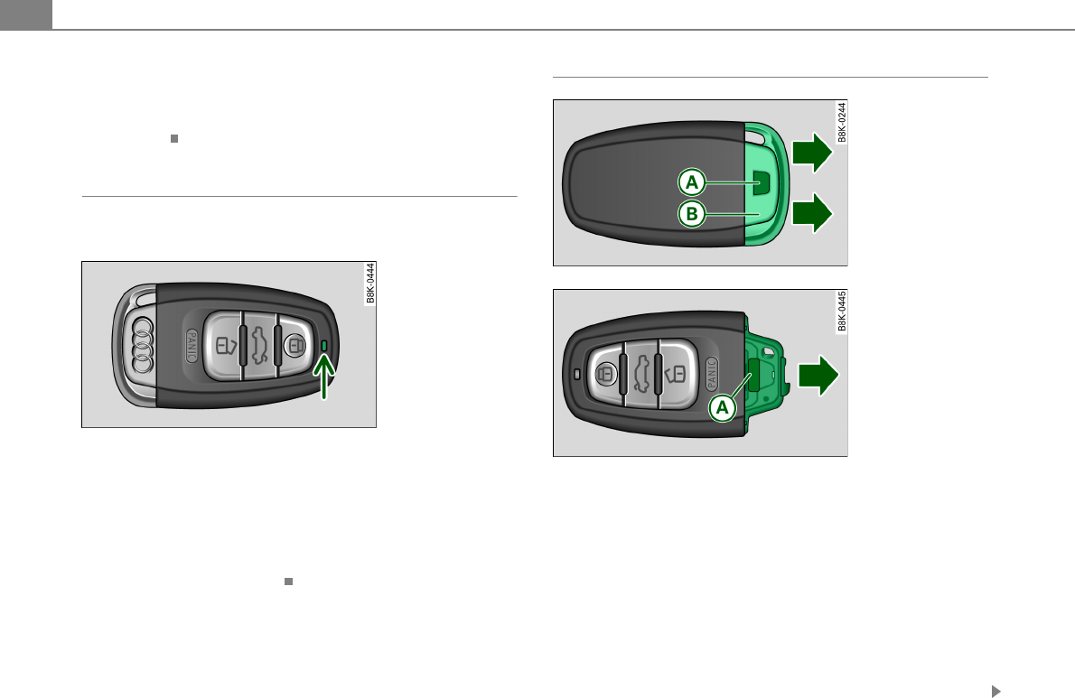
Opening and closing2
•If you open the driver’s door with the key left in the ignition lock,
a chime will sound. This is your reminder to remove the key and lock
the door.
•For security reasons, replacement keys are only available from
Audi dealers.
Check light in the master key
The check light in the master key provides information
about different conditions.
The check light comes on briefly once when a button is pressed, and
during an “inquiry” by the advanced key system.
If the check light does not come on, the battery is dead and has to
be replaced. In addition, when the battery is dead the § symbol
appears in the instrument cluster display as well as the message:
Please change key battery
Battery replacement ⇒page 2.
Master key battery replacement
We recommend having the battery changed by an autho-
rized Audi dealer. However, if you wish to replace the dead
battery yourself, proceed as follows:
– Press the release button ⇒fig. 3.
– Pull the mechanical key out of the master key.
– Press the release button ⇒fig. 4 on the battery holder
and at the same time pull the battery holder out of the
master key in the direction of the arrow.
– Install the new battery CR 2032 with the “+” sign facing
down.
Fig. 2 Check light in
the master key
Fig. 3 Remote master
key: Removing the
mechanical key
Fig. 4 Remote master
key: Removing the
battery holder
A
A
A
B
A
A
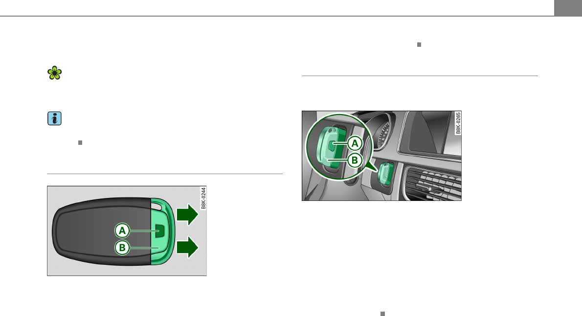
Opening and closing 3
– Push the battery holder carefully into the master key.
– Install the mechanical key.
For the sake of the environment
Dispose of dead batteries properly so as not to pollute the environ-
ment.
Tips
The replacement battery must be the same specification as the
original.
Removing the mechanical key
– Press the release button ⇒fig. 5.
– Pull the mechanical key out of the master key.
Using the mechanical key, you can
•Lock and unlock* the storage compartment on the passenger's
side [Cross reference error: reference link ID='Handschuhfach' not
found].
•Lock and unlock the lockable rear seat [Cross reference error:
reference link ID='Rueckenlehne-abschliessen' not found].
•Lock and unlock the vehicle manually ⇒page 9 if this should not
be possible with the master key.
Emergency unlocking of the ignition key
In the event of malfunctions in the electrical system, it
may happen that you cannot remove the ignition key.
If you are unable to remove the ignition key, for example
because the vehicle battery is discharged, proceed as
follows:
– Press the release button ⇒fig. 6 for example with a
ball point pen and pull the mechanical key out of the
master key.
– Lock the vehicle using the mechanical key ⇒page 9.
– Have the electrical system inspected by an authorized
Audi dealership.
Fig. 5 Remote master
key: Removing the
mechanical key
A
A
A
B
Fig. 6 Ignition switch
with ignition key
A
A
A
B
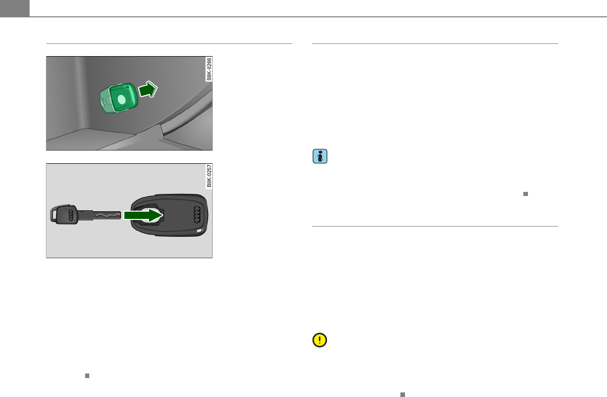
Opening and closing4
Starting the vehicle with the emergency key
– Take the adapter for the emergency key out of the glove
box ⇒fig. 7.
– Push the emergency key ⇒fig. 8 fully into the adapter.
Make sure that the Audi rings are facing up.
– Press the emergency key in the adapter down until it
latches audibly.
– Insert the adapter with the emergency key forward into
the ignition switch. The engine can now be started as
usual.
Electronic immobilizer
The immobilizer prevents your vehicle from being started
by unauthorized persons.
Inside the key there is a computer chip. This chip automatically
deactivates the electronic immobilizer when you insert the key in
the ignition lock. When you remove the key from the ignition lock,
the electronic immobilizer is automatically activated once again.
If an unauthorized key was used, SAFE is displayed continuously in
the odometer display field.
Tips
•Your engine can only be started using the factory-equipped key.
•You may not be able to start your vehicle if an ignition key of a
different vehicle make is also located on your set of keys.
Certification
The remote control device complies with
•USA models: Part 15 of the FCC Rules.
•Canada models: RSS-210 of Industry Canada.
Operation is subject to the following conditions:
•this device may not cause harmful interference, and
•this device must accept any interference received, including
interference that may cause undesired operation.
Note
The manufacturer is not responsible for ANY RADIO OR TV interfer-
ence caused by unauthorized modifications to this equipment.
Changes or modifications to this unit not expressly approved by the
party responsible for compliance could void the user's authority to
operate the equipment.
Fig. 7 Glove compart-
ment: Adapter for
emergency key
Fig. 8 Insert emer-
gency keyinto the
adapter
Opening and closing 5
Power locking system
General description
The power locking system locks or unlocks all doors and
the rear lid simultaneously.
You can lock and unlock the vehicle centrally. You have the following
choices:
•Remote master key ⇒page 6
•Door handles with advanced key* ⇒page 7,
•Lock cylinder at the driver's door ⇒page 9, or
•Power window switch inside ⇒page 9.
Selective unlocking
When they are closed, the door and rear lid are locked. When
unlocking, you can set in the radio or in the MMI* whether only the
driver's door or the entire vehicle should be unlocked ⇒page 6.
Automatic locking
The automatic locking feature locks all the vehicle doors and the
rear lid when you drive faster than 9 mph (15 km/h).
The car is unlocked again once the ignition key is removed. In addi-
tion, the vehicle can be unlocked if the opening function in the
power locking system switch or at one of the door levers is actuated.
The Auto Lock function can be turned on and off in the radio or in
the MMI* ⇒page 6.
Additionally, in the event of a crash with airbag deployment the
doors are automatically unlocked to allow access to the vehicle.
Anti-theft alarm warning system
If the anti-theft alarm warning system detects a break-in into the
vehicle, acoustic and visual warning signals are triggered.
The anti-theft warning system is activated automatically when you
lock the vehicle. It is deactivated when unlocking using the remote
key, with the mechanical key, and when you switch on the ignition.
The alarm also turns off when the alarm cycle has expired.
Turn signals
When you unlock the vehicle, the turn signals flash twice, when you
lock it once. If they do not flash, one of the doors, the rear lid or the
hood is not locked.
Unintentionally locking yourself out
In the following cases there safeguards to prevent you locking your
remote master key in the vehicle:
•If a door is open, the vehicle cannot be locked using the central
locking system switch ⇒page 9.
•On vehicles with advanced key*, if the most recently used master
key is in the luggage compartment, the rear lid is automatically
unlocked again after it is closed ⇒page 11.
Do not lock your vehicle with the remote master key until all doors
and the rear lid are closed. In this way you avoid locking yourself out
accidentally.
WARNING
•When you leave the vehicle, always remove the ignition key and
take it with you. This will prevent passengers (children, for
example) from accidentally being locked in the vehicle should they
accidentally press the power locking switch in the front doors.
•Do not leave children inside the vehicle unsupervised. In an
emergency it would be impossible to open the doors from the
outside without the key.
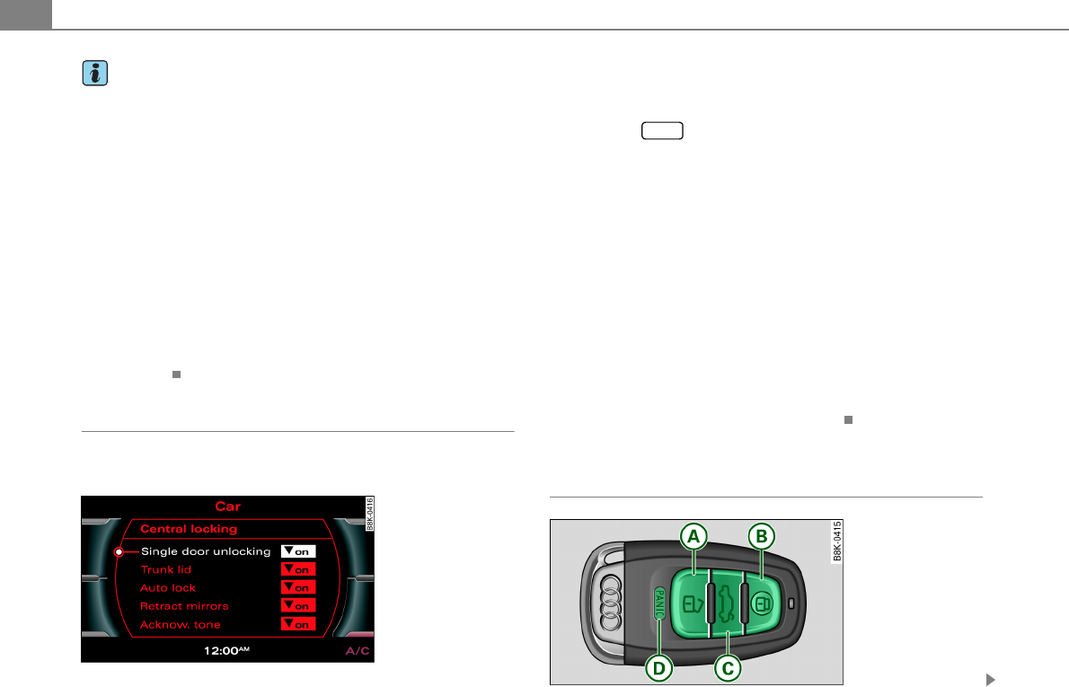
Opening and closing6
Tips
•In the event of a crash with airbag deployment all locked doors
will be automatically unlocked to give access to the vehicle occu-
pants from the outside.
•If the power locking system should malfunction, you can lock the
driver's door using the mechanical key ⇒page 10.
•If the power locking system should fail, you can still open the
fuel tank flap in an emergency [Cross reference error: reference link
ID='Tankklappe-not' not found].
•You are well advised not to keep valuables inside an unattended
vehicle, visible or not. Even a properly locked vehicle cannot provide
the security of a safe.
•If the LED in the upper edge of the driver's door panel comes on
for about 30 seconds after the vehicle is locked, there is a malfunc-
tion in the power locking or the anti-theft warning system. Have the
malfunction corrected by an authorized Audi dealership or qualified
repair facility.
Setting power locking
The driver can determine the functions for power locking
in the radio or in the MMI*.
In the Central locking menu you can decide which doors
should be unlocked with the remote key, and/or the
advanced key* when opening the vehicle.
– Press the function button.
– Select Central locking. The Central locking menu appears
⇒fig. 9.
For example, if you switch the item “Single door unlocking” on, the
passenger's door is no longer included in the power locking system,
and will not be unlocked by pressing the unlock button on the
master key remote control.
You can continue to unlock all the doors and the rear lid as before.
Press the opening button on the master key twice.
When locking the vehicle, all doors and the trunk lid are locked auto-
matically.
If you switch “Trunk lid” off, opening the rear lid at the handle
⇒page 11, fig. 17 is blocked. In this case the rear lid can be opened
with the button on the master key ⇒fig. 10 or with the unlocking
button in the driver's door ⇒page 11, fig. 16.
Unlocking and locking the vehicle with the
remote control
Fig. 9 MMI display:
Central locking menu
CAR
Fig. 10 Remote
control: function
buttons
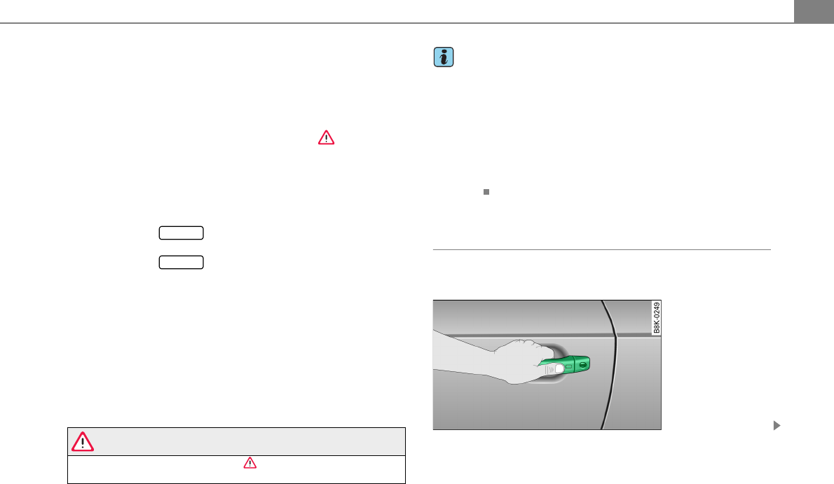
Opening and closing 7
Either the driver's door only or the entire vehicle will unlock
when the unlock button is pressed once, depending on
the settings in the MMI Central locking menu ⇒page 6.
– Press button Q ( ) to unlock the vehicle ⇒page 6,
fig. 10.
– Press button R ( ) to lock the vehicle ⇒ in “General
description” on page 5.
– Press button ( ) briefly to unlock the rear lid.
– Press the button for at least one second to open the
rear lid.
– Push the red button ( ) to activate the panic
function. The horn sounds and the turn signals flash.
Push the red button again to deactivate the
panic function.
If the vehicle is unlocked and no door, the rear lid or the hood is
opened within 60 seconds, the vehicle locks itself again automati-
cally. This feature prevents the vehicle from being accidentally left
unlocked over a long period of time.
It depends on the settings in the radio or in the MMI* whether the
entire vehicle is unlocked or only certain doors ⇒page 6.
On vehicles with advanced key*, the selector lever must be in the P
position, otherwise the vehicle cannot be locked.
WARNING
Read and follow all WARNINGS ⇒ in “General description” on
page 5.
Tips
•In order to make sure the locking function is working, you should
always keep your eye on the vehicle to make sure it is properly
locked.
•Do not use the remote control if you are inside the car, otherwise
you may unintentionally lock the vehicle, and then you would set off
the anti-theft alarm when you try to start the engine or open a door.
In case this happens anyhow, push the unlock button 0.
•Use the panic function only if you are in an emergency
situation.
Applies to vehicles: with advanced key
Locking and unlocking with advanced key
The doors and the rear lid can be unlocked and locked
without operating the master key.
A
A
A
A
A
B
A
C
PANIC
A
D
PANIC
Fig. 11 Advanced key:
Unlocking vehicle door
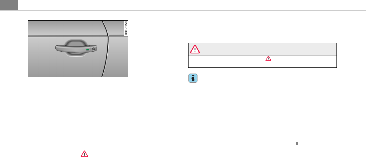
Opening and closing8
Unlocking vehicle
– Take hold of the door handle. The door is unlocked auto-
matically.
– Pull the handle to open the door.
Locking vehicle
– Move the selector lever to the P position (automatic
transmission), otherwise the vehicle cannot be locked.
– Touch the sensor at the door handle once ⇒fig. 12 to
lock the vehicle ⇒ in “General description” on page 5.
The vehicle can be locked and unlocked at any door. It depends on
the settings in the radio or in the MMI* whether the entire vehicle is
unlocked or one of the doors ⇒page 6. The master key must be
within a range of about 1.5 m from the appropriate door or the rear
lid. It makes no difference whether the master key is in your jacket
pocket or in your brief case.
If the area of the sensor in the door handle is touched while
unlocking ⇒fig. 12, this may adversely affect the opening function.
If you grip the door handle while locking, this can adversely affect
the locking function.
It is not possible to re-open the door for a brief period directly after
closing it. This allows you to ensure that the doors are properly
locked.
WARNING
Read and follow all WARNINGS ⇒ in “General description” on
page 5.
Tips
If your vehicle has been standing for an extended period, please
note the following:
•The proximity sensors are deactivated after a few days to save
power. You then have to pull on the door handle once to unlock the
vehicle and a second time to open the vehicle.
•To prevent the battery from being discharged and to preserve
your vehicle's ability to start for as long as possible, the energy
management system gradually switches off unnecessary conve-
nience functions. It is possible that you will not be able to unlock
your vehicle using these convenience functions.
Fig. 12 Advanced key:
Locking the vehicle
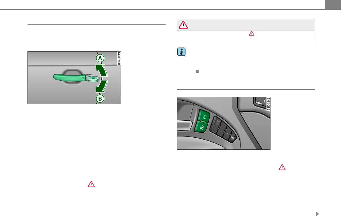
Opening and closing 9
Operating locks with the mechanical key
In the event of a failure of the power locking system, the
driver's door can locked and unlocked with the mechan-
ical keyat the lock cylinder.
To unlock the vehicle
– Insert the mechanical key into the lock of the driver’s
door.
– Turn the mechanical key to position ⇒fig. 13.
To lock the vehicle
– Move the selector lever to the P position (automatic
transmission).
– Close all windows and doors properly.
– Turn the mechanical key in the lock of the driver’s door to
the lock position ⇒ in “General description” on
page 5.
If the power locking system fails, there is emergency locking for the
passenger's door ⇒page 10.
WARNING
Read and follow all WARNINGS ⇒ in “General description” on
page 5.
Tips
•After the ignition is switched on, the power locking system
switch and the unlocking button for the rear lid in the door are
enabled.
Locking and unlocking the vehicle from inside
– Press the button to unlock the vehicle ⇒fig. 14.
– Press the button to lock the vehicle ⇒.
If you lock the vehicle using the power locking switch, please note
the following:
•If a door is open, the vehicle cannot be locked using the power
locking system switch.
•You cannot open the doors or the rear lid from the outside
(increased security, for example when you are stopped at a red
light).
Fig. 13 Key turns for
opening and closing
A
A
A
B
Fig. 14 Driveàs door:
power locking switch
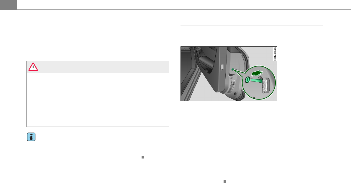
Opening and closing10
•The diodes in the power locking switch illuminate when all the
doors are closed and locked.
•You can unlock and open the doors from the inside by pulling on
the door handle.
•If you have a crash and the airbag is activated, the doors auto-
matically unlock.
WARNING
•The power locking switch works with the ignition off and auto-
matically locks the entire vehicle when it is actuated.
•On a vehicle locked from the outside the power locking system
switch is inoperative.
•Locking doors from the inside can help prevent inadvertent
door opening during an accident and can also prevent unwanted
entry from the outside. Locked doors can, however, delay assis-
tance to vehicle occupants and hold up rescue efforts from the
outside in an accident or other emergency.
Tips
Your vehicle is locked automatically at a speed of 9 mph (15 km/h)
(Auto Lock) ⇒page 5. You can unlock the vehicle again using the
opening function in the power locking system switch.
Emergency locking of the passenger's door
If the power locking system fails (power failure), you will
need to lock the passenger door separately.
An emergency locking mechanism is integrated in the edge
of the passenger's door (only visible when the door is open).
– Take the mechanical key out of the master key ⇒page 3.
– Open the door.
– Pull the protective cover out of the hole ⇒fig. 15.
– Insert the mechanical key into the inner slot and turn it
to the right as far as it can go.
After you close the door, you will no longer be able to open it from
the outside. The door can be opened from the inside by pulling once
on the door handle.
Fig. 15 Emergency
locking of the
passenger's door
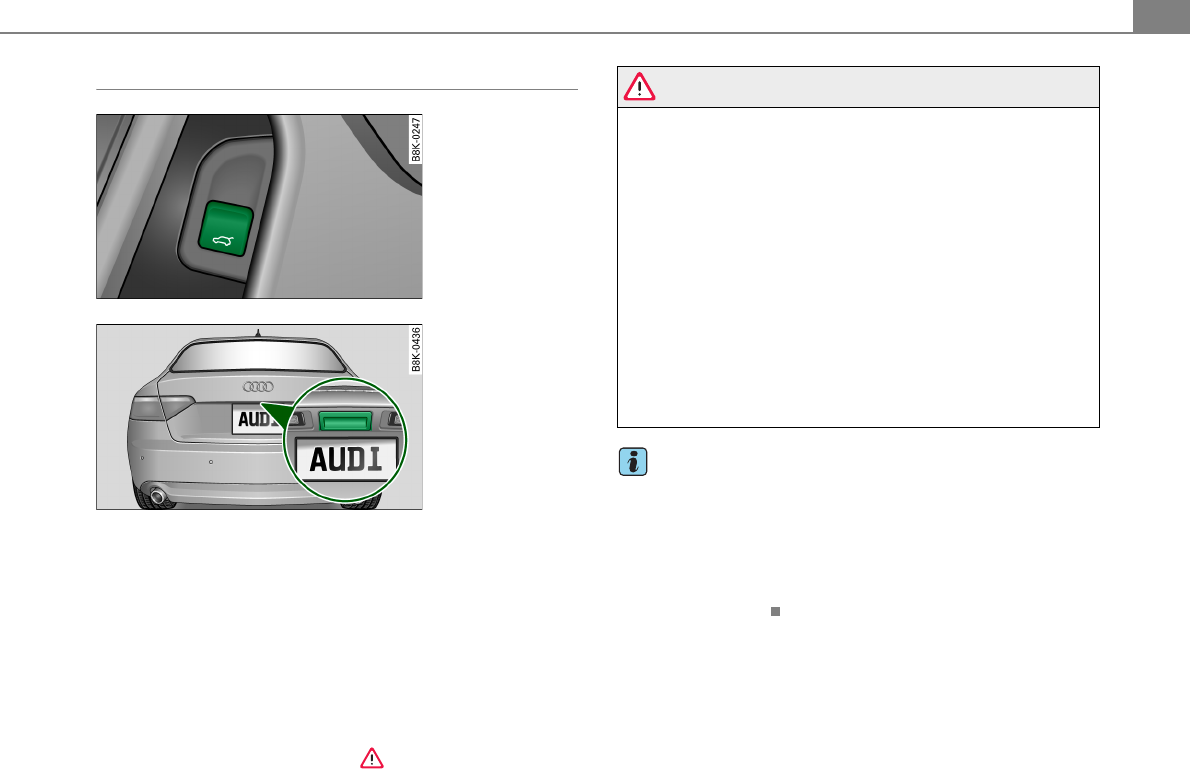
Opening and closing 11
Opening and closing rear lid/trunk lid
Opening the rear lid
– Press the middle button on the remote control master
key for at least one second, or
– Pull the release button in the driver's door ⇒fig. 16.
The rear lid unlocks and opens, or
– Press the handle on the rear lid ⇒fig. 17.
Closing the rear lid
– Pull the rear lid down at the grip on the inside and allow
it to drop gently to close it ⇒.
WARNING
•After closing the rear lid, always pull up on it to make sure that
it is properly closed. Otherwise it could open suddenly when the
vehicle is moving.
•To help prevent poisonous exhaust gas from being drawn into
the vehicle, always keep the rear lid closed while driving. Never
transport objects larger than those which fit completely into the
luggage area, because then the rear lid cannot be fully closed.
•Never leave your vehicle unattended especially with the rear lid
left open. A child could crawl into the car through the luggage
compartment and pull the lid shut, becoming trapped and unable
to get out. To reduce the risk of personal injury, never let children
play in or around your vehicle. Always keep the rear lid as well as
the vehicle doors closed when not in use.
•Always ensure that no one is within range of the rear lid when
it is moving, in particular close to the hinges - fingers or hands can
be pinched.
Tips
•When the vehicle is locked, the rear lid can be opened separately
by pressing the button on the master key. When you close the
rear lid again, it locks automatically.
•If the rear lid is open or not properly closed when the ignition is
turned on, the door and rear lid warning [Cross reference error:
reference link ID='Tuerwarnung' not found] appears in the instru-
ment cluster display.
Fig. 16 Driver's door:
remote rear lid release
Fig. 17 Position of
handle in the rear lid
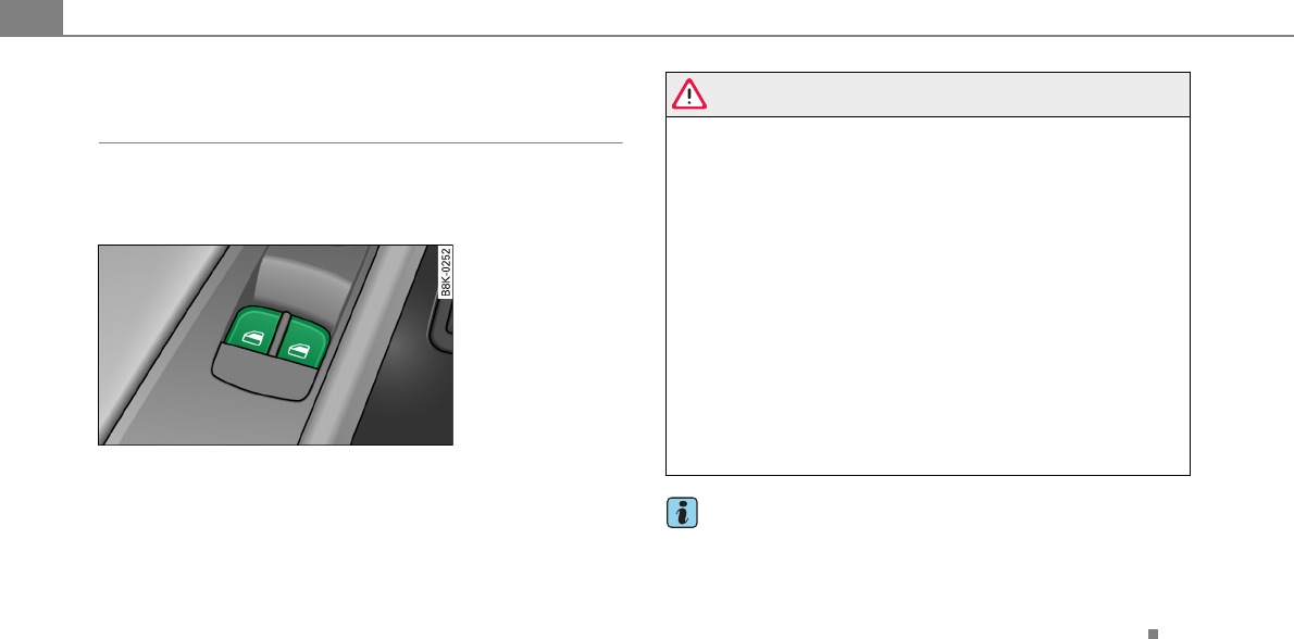
Opening and closing12
Power windows
Controls
The driver can operate the window regulator for the
driver's door with the left switch and the window regu-
lator for the passenger's door with the right switch.
If the respective switch is pushed or pulled the window will
open or close. The power window switches have a two-posi-
tion function:
Opening the windows
– Push the switch to the first stop and hold it there until the
window has lowered to the desired position.
– Push the switch briefly to the second stop: the window
will automatically open all the way.
Closing the windows
– Pull the switch up to the first stop and hold it there until
the window has risen to the desired position.
– Pull the switch quickly to the second position: the
window will automatically close all the way.
WARNING
•Do not leave children unattended in the vehicle, especially with
access to vehicle keys. Unsupervised use of the keys can result in
starting of the engine and use of vehicle systems such as power
windows, etc. which could result in serious injury.
•Remember – you can still open or close the power windows for
about ten minutes after the ignition is switched off. Only when
either of the doors are opened are the power windows switched
off.
•Be careful when closing the windows. Check to see that no one
is in the way, or serious injury could result!
•Always remove the ignition key whenever you leave your
vehicle.
•If you lock your vehicle from the outside, no one, especially chil-
dren, should remain in the vehicle.
•Do not stick anything on the windows or the windshield that
may interfere with the driver’s field of vision.
Tips
•When you open the doors, the windows automatically lower
about 10 mm.
•After the ignition has been switched off, the windows can still be
opened or closed for about 10 minutes. The window regulators are
not switched until the driver's or passenger's door is opened.
Fig. 18 Driver's door:
power window
switches