HID Global 0006A Proximity Reader User Manual 5365 910 manual
HID Global Corporation Proximity Reader 5365 910 manual
Contents
- 1. 5365 910 manual
- 2. 5395 902 manual
- 3. 6005 910 manual
5365 910 manual

REV DESCRIPTION DATE APPROVED
1 INITIAL RELEASE PER EO #E5365-44
-01 Part: Sheets 1 through 4
-02 Part: Sheets 1 through 5
NOTE: Cover sheet is for Revision Control only, and is not to be sent with document.
REV
SHEET 34 35 36 37 38 39 40 41 42 43 44 45 46 47 48 59 50 51
REV
SHEET 16 17 18 19 20 21 22 23 24 25 26 27 28 29 30 31 32 33
REV STATUS 11111 1
OF SHEETS 0123456789101112131415
TOLERANCES APPROVALS DATE HID CORPORATION
.XX = +/- .03” DWN Andresky 060500 IRVINE, CALIFORNIA
.XXX = +/- .010” CHK Installation Manual,
ANGLES = +/- 1°APVD Miniprox Reader
MATERIAL N/A APVD
FINISH N/A P/N 5365-910 REV 1
SCALE N/A
THIS DOCUMENT CONTAINS PROPRIETARY
INFORMATION. IT MAY NOT BE DISCLOSED TO
OTHERS OR USED FOR MANUFACTURING
PURPOSES WITHOUT THE PERMISSION OF HID
CORPORATION. SIZE A SHEET 0 OF 5

_____________________________________________________________________________________________________
HID Corporation 9292 Jeronimo Road Irvine, CA 92618-1905 USA TEL (949) 598-1600 (800) 237-7769 FAX (949) 598-1690
Web page, E-mail - www.hidcorp.com - Miniprox Installation Manual 5365-910 Rev 1
1
Install Manual – 5365-910 Rev 1
MiniproxTM Installation Manual

_____________________________________________________________________________________________________
HID Corporation 9292 Jeronimo Road Irvine, CA 92618-1905 USA TEL (949) 598-1600 (800) 237-7769 FAX (949) 598-1690
Web page, E-mail - www.hidcorp.com - Miniprox Installation Manual 5365-910 Rev 1
2
PARTS LIST (Included)
Quantity
- MiniproxTM Reader with snap-on cover and 18” cable
(For terminal block versions no cable is supplied)
1
- #6-32 x 1” self-tapping panhead screw
2
- Installation manual 1
- Junction box (Hazardous installation version only)
1
PARTS LIST (Not-Included)
Quantity
- Wire splice 9
- DC Power supply 5.0 VDC or 12 VDC
2
Mounting Instructions
• Determine an appropriate mounting location. The
reader may be mounted to any surface, including
metal.
• Drill two (2) 3/32-inch (2.5mm) holes approximately
1 inch deep for mounting the reader.
• Drill a 5/8-inch (16mm) hole for the cable.
• Remove the snap-on cover from the reader and
secure the reader to the mounting surface.
• Route the cable from the reader and/or power
supply to the host. A linear type power supply is
recommended. Check all electrical codes for proper
cable installation.
• For best operation, the drain wire should be
disconnected at the power supply end of the cables.
• For the cable connection to the Panel - Use Alpha
#1299C or equivalent.
• Test the operation of the reader. After completion of
the test, replace the snap-on cover.
• See sheet 3 of this manual for the appropriate
dimensioned drawings.
Connecting the Reader to the Host
Connect the reader to the host according to the wiring
table below and the host installation guide.
Wiegand
Clock & Data
Wire Color
Terminal Number
+DC
+DC
Red
TB1-1
Ground
Ground
Black
TB1-2
Data0
Data
Green
TB1-3
Data1
Clock
White
TB1-4
Shield Ground
Shield Ground
Drain
TB1-5
Green LED
Green LED
Orange
TB1-6
Red LED
Red LED
Brown
TB1-7
Beeper
Beeper
Yellow
TB1-8

_____________________________________________________________________________________________________
HID Corporation 9292 Jeronimo Road Irvine, CA 92618-1905 USA TEL (949) 598-1600 (800) 237-7769 FAX (949) 598-1690
Web page, E-mail - www.hidcorp.com - Miniprox Installation Manual 5365-910 Rev 1
3
Hold
Hold
Blue
TB1-9
---
Card Present
Violet
TB1-10
Testing and Operation
• When power is applied to the reader the LED will
flash green three (3) times while the beeper beeps
simultaneously. The LED will then turn red. This
indicates that the microcontroller is operating
properly.
• Present an ID card to the reader. The LED will
momentarily turn green while the beeper beeps once,
indicating that the card was read successfully.
Important Product Specifications
Power requirements (linear supply)
Operating Voltage Range 5.0 – 16.0 VDC
Absolute Maximum Voltage 18 VDC
Peak Current 80 Ma
Average Current 5V or 12V 20 Ma
Maximum cable distance 500 ft (153 m)
To host
FCC Compliance Statement: This device complies with
part 15 of the FCC rules. Operation is subject to the
following two conditions: (1) this device may not cause
harmful interference, and (2) this device must accept
any interference received, including interference that
may cause undesired operation.
_____________________________________________________________________________________________________
HID Corporation 9292 Jeronimo Road Irvine, CA 92618-1905 USA TEL (949) 598-1600 (800) 237-7769 FAX (949) 598-1690
Web page, E-mail - www.hidcorp.com - Miniprox Installation Manual 5365-910 Rev 1
4
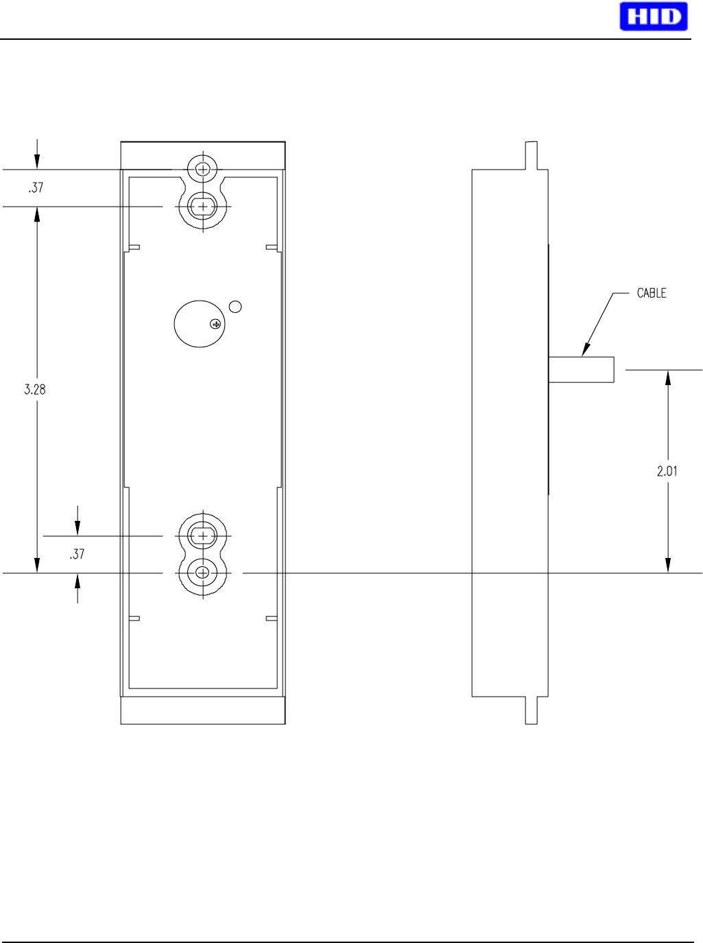
Pigtail Installation
Figure 1
_____________________________________________________________________________________________________
HID Corporation 9292 Jeronimo Road Irvine, CA 92618-1905 USA TEL (949) 598-1600 (800) 237-7769 FAX (949) 598-1690
Web page, E-mail - www.hidcorp.com - Miniprox Installation Manual 5365-910 Rev 1
5
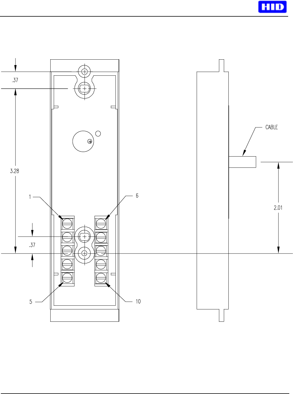
Terminal Block Installation
Figure 2
_____________________________________________________________________________________________________
HID Corporation 9292 Jeronimo Road Irvine, CA 92618-1905 USA TEL (949) 598-1600 (800) 237-7769 FAX (949) 598-1690
Web page, E-mail - www.hidcorp.com - Miniprox Installation Manual 5365-910 Rev 1
6
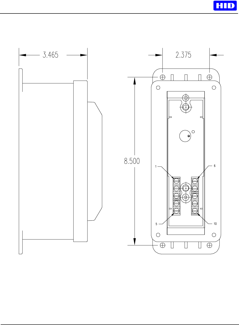
Hazardous Location Installation (Pigtail or Terminal Block)
Figure 3