HID Global 0006A Proximity Reader User Manual 5365 910 manual
HID Global Corporation Proximity Reader 5365 910 manual
UserManual.wiki
>
HID Global
>
0006A User Manual
>
5365 910 manual
Contents
1.
5365 910 manual
2.
5395 902 manual
3.
6005 910 manual
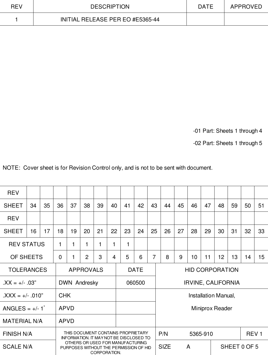
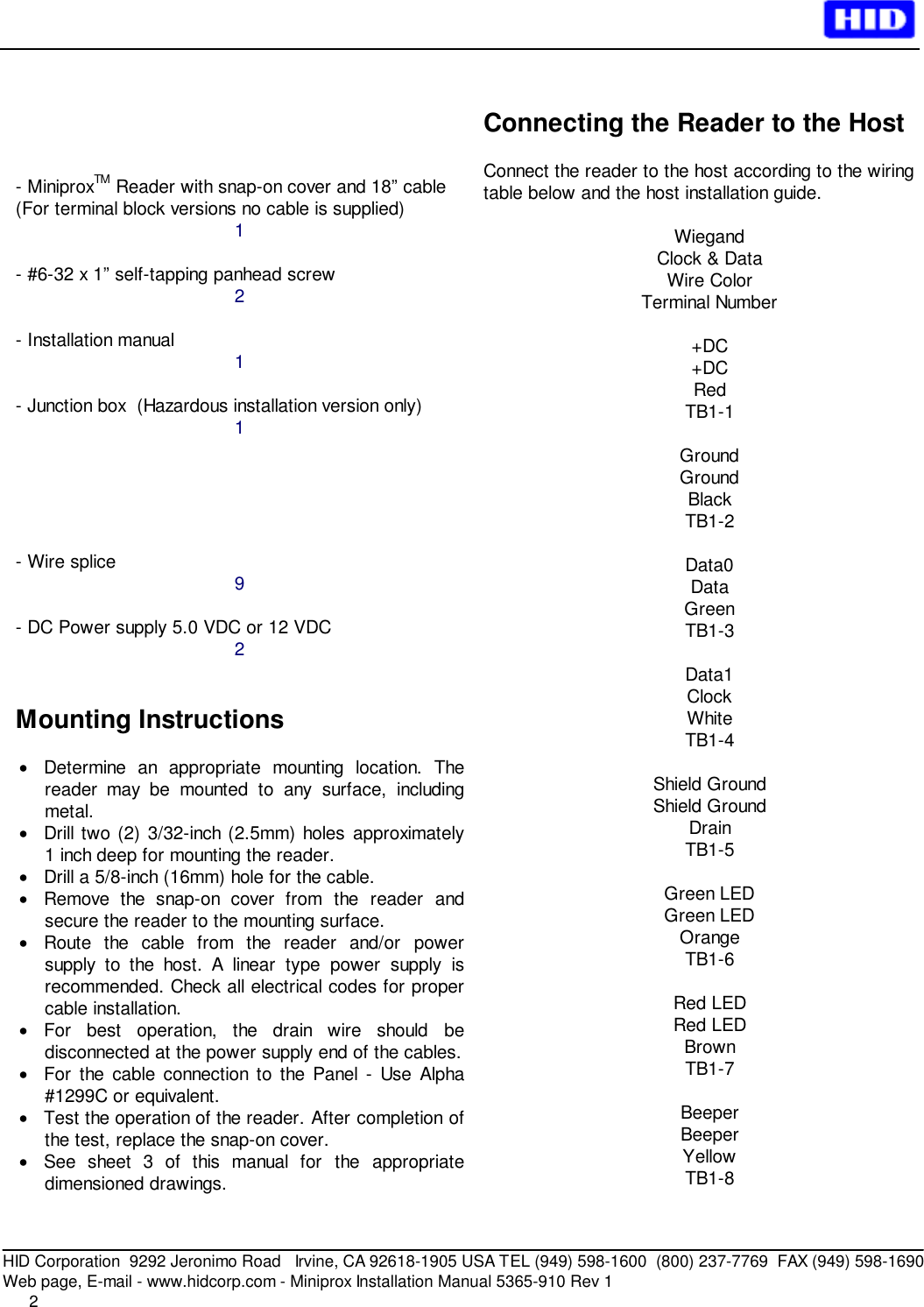
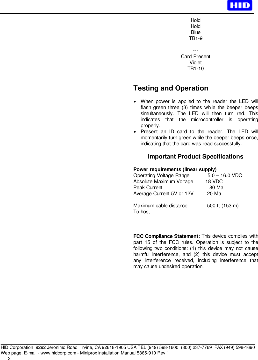
5365 910 manual
Navigation menu
Upload a User Manual
Namespaces
Wiki Guide
HTML
PDF
Info
Views
User Manual
Discussion / Help
Navigation