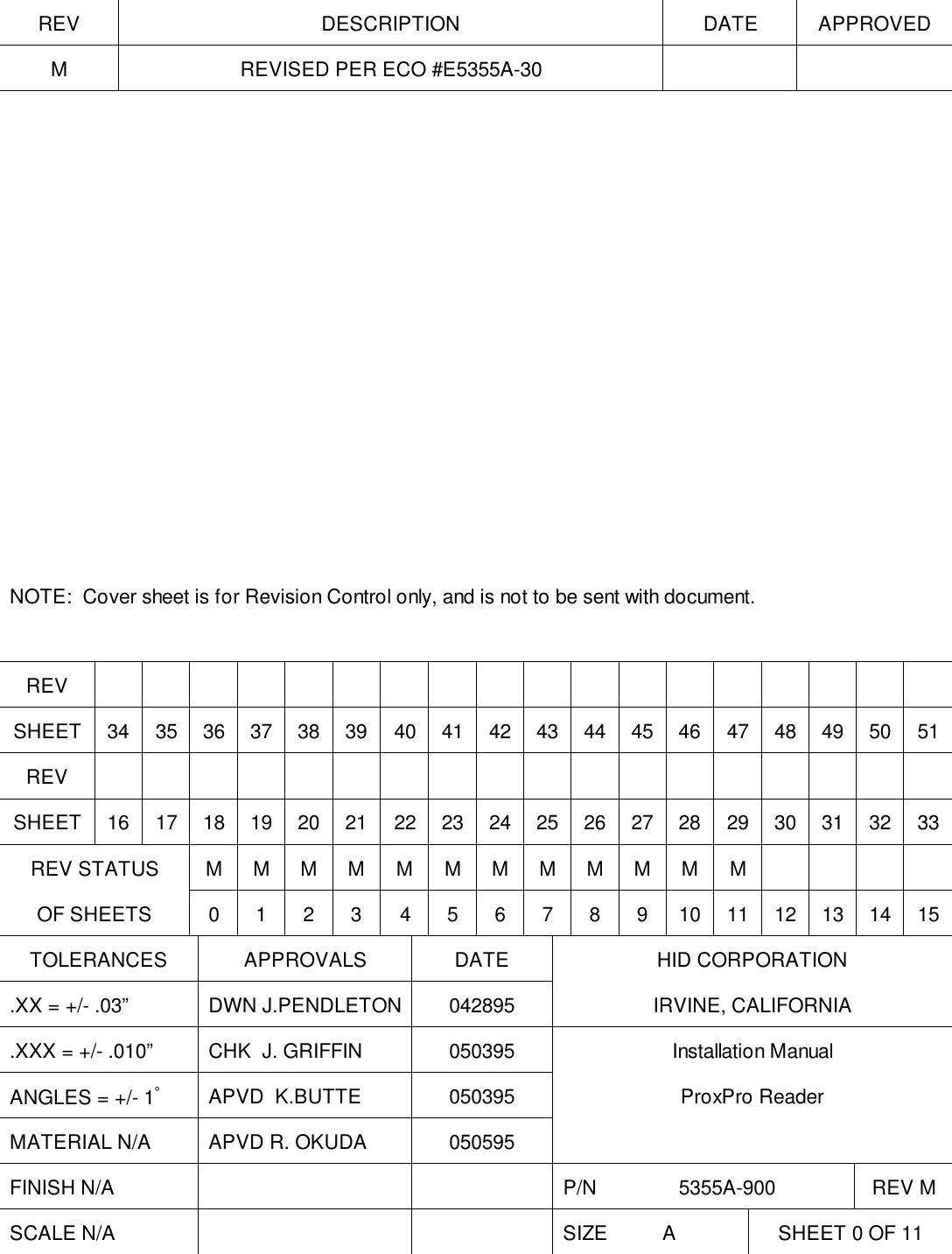
HID Global 535Y ProxPro 5355/8A(5355-300) and ProxPro Plus 6030/8A User Manual

HID Global Corporation ProxPro 5355/8A(5355-300) and ProxPro Plus 6030/8A

user manual

REV DESCRIPTION DATE APPROVEDM REVISED PER ECO #E5355A-30NOTE:  Cover sheet is for Revision Control only, and is not to be sent with document.REVSHEET 34 35 36 37 38 39 40 41 42 43 44 45 46 47 48 49 50 51REVSHEET 16 17 18 19 20 21 22 23 24 25 26 27 28 29 30 31 32 33REV STATUS MMMMMMMMMMMMOF SHEETS 0123456789101112131415TOLERANCES APPROVALS DATE HID CORPORATION.XX = +/- .03” DWN J.PENDLETON 042895 IRVINE, CALIFORNIA.XXX = +/- .010” CHK  J. GRIFFIN 050395 Installation ManualANGLES = +/- 1°APVD  K.BUTTE 050395 ProxPro ReaderMATERIAL N/A APVD R. OKUDA 050595FINISH N/A P/N               5355A-900 REV MSCALE N/A SIZE          A SHEET 0 OF 11
____________________________________________________________________________________________          HID Corporation  9292 Jeronimo Road  Irvine, CA 92618  USA  TEL (949) 598-1600   (800) 237-7769   FAX (949) 598-1690          Web page, E-mail -www.hidcorp.com              ProxPro Reader Installation Manual        5355A-900 Rev M                   1 of 11Installation Manual – 5355A-900 Rev MProxPro Reader - Wiegand/Clock and Data 5355/8A
____________________________________________________________________________________________          HID Corporation  9292 Jeronimo Road  Irvine, CA 92618  USA  TEL (949) 598-1600   (800) 237-7769   FAX (949) 598-1690          Web page, E-mail -www.hidcorp.com              ProxPro Reader Installation Manual        5355A-900 Rev M                   2 of 11ProxPro Reader™ Wiegand/Clock-Data Installation ManualSystem OverviewThe ProxPro reader is a self contained proximity reader. The two piece polycarbonate enclosure has an rubberGasket that seals the pieces together and a cable fitting that seals the cable entry. The water resistant unit isapproved for outdoor use. The enclosure is designed to fit on a single gang electrical box. A Bi-color LED andaudible tone enhance user feedback. A tamper switch feature is available that will alert the Host when theenclosure is opened. An internal DIP switch makes the configuration of the outputs, audible tone, keypad andLED control options simple.Installation of the ProxPro reader consists of mounting, verifying the DIP switch settings, setting a tuning jumperand connecting the cable to the Host.OperationAccess Cards may be presented to either the front or the back of the reader. Optimum read range is achievedwhen the access card is presented face on, and parallel to the reader face. The LED is normally controlled bythe internal reader firmware. Alternatively, the LED can be controlled by the access control host panel. Whenthe LED is controlled directly by the reader, the LED normal state is red, and indicates that the reader is readyto read an access card. The LED turns green when the access card is read and the message is transmitted tothe Host system. When the reader is ready for another access card, the LED returns to red. The typical timethe LED is green is 250 milliseconds . The reader only controls the green state of the LED, there is no amberLED state. The operation of the LED may be controlled by the Host.  When the LED is host system controlled,the LED and beeper operation may vary depending on the particular host software.  The LED may then exhibit ared, green or “amber” color for certain status conditions as controlled by that host’s software.Parts List1) ProxPro Reader qty 1 (included)2) #6-32 x 1 self tapping screws, Type T or 23 qty 2 (included)3) Installation Manual qty 1 (included)4) Cable Fitting qty 1 (included)5) Cable, 5 conductor, 22awg as required (max. 500 feet)(Alpha 1295 C or equivalent) See cable notes.6)  Cable, 20 conductor, 22awg as required (max. 500 feet)(Alpha 1299/20C or equivalent) See cable notes.7) DC Power Supply 12V/100mA or 24V/120mA 1 (Installer supplied)8) In the E.U. the recommended power supply is the Micro State Electronics Model PS-5.Installation Procedure1. Determine an appropriate mounting position for the reader.  The reader drawing below is actual size andmay be used as a template.  Install a single or double gang electrical box or drill the appropriate mountingfor #6 fasteners.  If mounting to a metal surface, drill two 7/64 (.109) inch holes and use the enclosed selftapping screws for mounting.2. Route the interface cable from the reader and/or power supply to the Host.3. Prepare the cable by cutting the cable jacket back 2 (two) inches and strip the wires 1/4 inch. Tinning thewires is not required.4. Pry off the center face plate by placing a thin blade into the grove that outlines the face of the reader.  Usecare to avoid scratching the surface of the reader.  The face plate is attached to the reader by frictiononly.  The screws that hold the enclosure pieces together will be exposed.  Loosen the four screws to openthe enclosure (the enclosure screws are captive to the cover).5. Install the cable fitting on the rear of the reader.  Feed the cable through the cable fitting, tighten the fittingnut so the cable jacket is flush with the printed circuit board.  Dress the cable conductors and connect thereader to the Host according to the terminal descriptions in the dimension diagram and wiring table.  The
____________________________________________________________________________________________          HID Corporation  9292 Jeronimo Road  Irvine, CA 92618  USA  TEL (949) 598-1600   (800) 237-7769   FAX (949) 598-1690          Web page, E-mail -www.hidcorp.com              ProxPro Reader Installation Manual        5355A-900 Rev M                   3 of 11descriptions are on the PCB guard in the reader.  Connect the drain line of the shield to terminal 2 (PowerSupply Ground).  Terminal 5, Data Return, is to be connected to the ground of the Host if the power supplyground is not common with the Host.  The opposite end of the drain line should be cut flush with the jacketand left disconnected.6. If the tamper feature is available on the Host, connect the tamper switch using the connectionsrecommended by the Host documentation. The switch is a single pole, double throw. When the inner readercover is removed, the tamper switch is released. The TB1 connections to the tamper switch are pins 10 and11.  Pin 10 is the common contact of the switch and pin 11 is either the normally open or closed. Jumper P3selects the contact of the tamper switch, either the normally closed or the normally open contact. Thedefault position is P3 across pins 1 and 2. This selects the normally open contact on TB1 pin 11. If thenormally closed contact is required, move P3 across pins 2 and 3. (Note - “normally open and normallyclosed refer to the Pin 11 status while the cover is removed.)  The contacts are rated for 100mA at 35 VDC.7. Mount the base of the reader that holds the electronics to the gang box or surface using the two holeslocated on the center axis of the reader.  Two #6-32 x 1 inch screws are provided for mounting to a gangbox or metal surface.8. Set the DIP switches according to the table in the section, DIP Switch Settings.9. Place the jumper on P1 between pins 1 and 2 when mounting to a metallic surface or to a junction boxwith a metal cover plate.  Otherwise, the jumper should be between pins 2 and 3, the default position.10. After wiring the Reader and power supply, the Reader is ready to be tested.  Power up the Reader and theLED and Beeper will flash and beep 3 times in a sequence of two short delays and one long delay. Thisindicates that the micro-controller unit is working properly.  If the switches have been set for external controlonly, the Reader will 3 shorts and a long. Present an ID card to the Reader and the LED should momentarilyturn green, indicating a read of the card.  If the Reader LED is controlled by the Host refer to the Hostdescription of the LED operation.11.  Replace the top cover and face plate.Standard Wire ConnectionsTB112345678910 11+DC Ground Data0/Data Data1/Clock ShieldGround GreenLED Red LED Beeper Hold/CardPresentTamperCommon TamperSelectRed Black Green White Violet Orange Brown Yellow Blue -- --Buffered Direct Wire Connections – Option D10 11 E1 E2 E3 E4 E5 E6 E7 E8 E9 E10TamperCommon TamperSelect +DC Ground Row 1 Row 2 Row 3 Row 4 Column1Column2Column3SelectLowRed /Black Red /Green White /Red White /Black Gray Violet Red /Yellow Pink Tan White /Blue White /Green White /YellowDirect Wire Connections – Option STB21234567Row 1 Row 2 Row 3 Row 4 Column3Column2Column1Red Black Green White Drain Orange Brown
____________________________________________________________________________________________          HID Corporation  9292 Jeronimo Road  Irvine, CA 92618  USA  TEL (949) 598-1600   (800) 237-7769   FAX (949) 598-1690          Web page, E-mail -www.hidcorp.com              ProxPro Reader Installation Manual        5355A-900 Rev M                   4 of 11Cable Notes:1) When using 5 conductor cable, the power supply and Host must have a common ground (voltagereference).2) 6 conductor cable is required when controlling the red and green LED.   (Alpha 1296 C or equivalent)3) 7 conductor cable is required when both green and red LED’s are controlled by the Host  and the powersupply and Host "ground" are separate.  (Alpha 1297 C or equivalent)4) A 22 AWG twisted pair, shielded, stranded cable is often required for the tamper switch.  Follow therecommendations of the manufacturer of the Host system.  If the tamper input is a supervised input the "endof line" resistors may be mounted in the enclosure.  Use extreme care and shield any bare wire from theprinted circuit assembly and its components. 5) The inner diameter of the cable fitting will accommodate a cable with an outer diameter of .300 inches(nominally).6)  Connect cable shield by connecting drain wire to TB1-2 ground.  Leave foil and drain wire disconnected athost end of cable by cutting them off at the end of the cable jacket.7)  When using the Buffered Direct Connect ProxPro with a 20 conductor cable, DC+ and Power (Red andWhite / Red wires) must have a common connection to the host +DC power supply.  The two ground wires(Black and White / Black) must have a common ground connection to the host +DC power supply.
____________________________________________________________________________________________          HID Corporation  9292 Jeronimo Road  Irvine, CA 92618  USA  TEL (949) 598-1600   (800) 237-7769   FAX (949) 598-1690          Web page, E-mail -www.hidcorp.com              ProxPro Reader Installation Manual        5355A-900 Rev M                   5 of 115.00" (127mm)3.28" (83.3mm)5.00" (127mm)1.00" (25.4mm)OOOOOOOOOOTB12 - GND3 - DATA "0"4 - DATA "1"5 - DATA RTN1 - DC +TAMPER SW SW1P1P2mounting holes (2 places)Dimension Drawing (Actual Size)7 - Red LED6 - Green LED8 - Beeper9 - Hold1 - n/o3 - n/c10 - COMO  11 - Tamper123DIP Switch Settings - Switch 1
____________________________________________________________________________________________          HID Corporation  9292 Jeronimo Road  Irvine, CA 92618  USA  TEL (949) 598-1600   (800) 237-7769   FAX (949) 598-1690          Web page, E-mail -www.hidcorp.com              ProxPro Reader Installation Manual        5355A-900 Rev M                   6 of 11Switch 1-1 Hardware IdentityWhen set in the "on" position the unit is configured for "Wiegand" interface.  The "off" position configures the unitfor "Clock and data" interface.Switch 1-2 Audible Tone ControlThe Audible Tone (Beeper) may be enabled or disabled to sound when an access card is read. When enabled,the audible tone is sounded when the a card is successfully read.  When the Beeper is disabled, the onlymethod to activate the Beeper is to use the external Beeper control line.  The Beeper will turn on when thecontrol line is switched to ground.   Switch 2 in the "on" position enables the audible tone (the default).Switch 1-3 Green LED ControlThe Green LED can be configured to turn on, or not turn on when an access card is read.  Switch 3 in the “off”position selects the Green LED to be turned on (the default).Switch 1-4 Keypad OperationThe keypad inputs may be processed by the reader or may be connected directly to the Host.  When thekeypad inputs are processed by the reader, the reader scans the keypad and outputs the keypad entries overthe "Wiegand" interface.  When the keypad is connected to the Host, the Host determines which key is beingentered.  Switch 4 is in the "on" position for the default mode (the keypad inputs are processed by the reader).Switch 1-5 Single / Dual LED ControlIn Single LED Control the LED is Red.  When an access card is read, the LED toggles Green, and then back toRed.  Grounding the Green LED Control line will change the LED from Red to Green.  The reader maybeconfigured so the Green LED is externally controlled independently from the Red LED.  This is referred to asDual LED Control.  When the Red or Green LED Control line is switched to ground, the respective LED isturned on.  If both LED’s are on, the LED appears to glow amber.  Switch 5 in the “off” position selects SingleLED Control (the default).Switch 1-6 and 1-7 Data Output BiasingThe data outputs may be configured as open collector or biased at 5VDC through 1k Ohm resistors by thereader.  The default (standard) configuration is output biasing, with switches 6 and 7 "on" .  Note: When theoutputs are configured as open collector, the host panel should provide bias voltage at the panel inputs.KeyPadBeeper ControlHardware IdentityonDefault Settingononononononoff(The keypad data is sent on data lines), N/A for D version(Identifies the unit to be "Wiegand")12345678Single/Dual LED CNTL(Single Line LED Control)offGreen LED ControlNot used(The Wiegand data outputs are pulled up to +5VDC through a 1kOhm resistor)(The green LED is enabled when a card is read)( The beeper is enabled when a card is read)Wiegand Data 0 BiasWiegand Data 1 BiasKeypad Option Notes:This section of this document describes the keypad interface.  The keypad has twelve keys, four rows by threecolumns. The characters 0 to 9, # and * are arranged the same as a standard telephone keypad. There are twomethods for interfacing to the Keypad.The first configuration (K version, internal keypad) processes the keypad entries in the reader and thentransmits the data to the host system via the Wiegand data lines. The reader outputs each key as an ASCIIencoded hexadecimal digit. The decoding of the message sent through the Wiegand interface is the only
____________________________________________________________________________________________          HID Corporation  9292 Jeronimo Road  Irvine, CA 92618  USA  TEL (949) 598-1600   (800) 237-7769   FAX (949) 598-1690          Web page, E-mail -www.hidcorp.com              ProxPro Reader Installation Manual        5355A-900 Rev M                   7 of 11processing required of the host system.  The user interface has been implemented in the most generic fashionto give the integrator the most flexibility.The Second configuration  (S version, direct connect keypad), the host must scan the keypad directly using aseparate cable.K Version - Internal keypad processingParity and Length options must be factory configured. Contact customer service to enable these options.Parity OptionThe default does not included parity in the data message.  When the parity option is enabled, parity is added tothe total message independent of length.  The parity coverage is diagrammed below.  Each parity bit coversexactly one half of the message.P XXXXXXXX......XXXXXXXXPEXXXXXXXX......XXXXXXXXP      Length Buffer keys) OptionThe length option chooses the number of key entries that will be buffered before the message is sent to thehost.  The maximum number of entries is 10 with parity and 11 without parity.  When the option is set formultiple entries the reader has a five (5) second timer that will clear all entries after five seconds has expiredbetween entries.  The length option requires the user to enter the programmed number of key entries.  Uponcompletion of the last key entry, the message is assembled and sent.  Parity is added if the option is set.  Thisrequires the system integrator to configure the reader for the number of key entries before installation.User InterfaceThe user is able to press keys at any time.  Card reads and  key entries are independent of each other, theuser is not required to follow any sequence, unless specified by the system integrator.  The reader is equippedto give the user audible, visual and tactile feedback when a key is pressed.  The amount of time is 5 (five)seconds between key entries when the multiple key entry option is used.  If the time expires between keyentries, all keys entered are cleared and the user must start the sequence from the beginning.Keypad MessageThe keypad message follows a basic format.  The entries are transmitted in the hexadecimal representation.When parity is added, the message format mimics the "standard 26 bit Wiegand format" .  The key that ispressed is represented in Hexadecimal with * represented by A (HEX) and # represented by B (HEX).0 = 0000 4 = 0100 8 = 10001 = 0001 5 = 0101 9 = 10012 = 0010 6 = 0110 * =  10103 = 0011 7 = 0111 # = 1011Example: without parity:AAAA BBBB CCCC DDDD .....   KKKKAAAA = The first key enteredBBBB = The second key enteredKKKK = The eleventh key entered (the maximum)Example: with parity:A message that has a fixed number of key entries set to 4 and the parity option included.P AAAA BBBB CCCC DDDD PA - the first key enteredB - the second key enteredC - the third key enteredD - the fourth key enteredP - Parity Bits.
____________________________________________________________________________________________          HID Corporation  9292 Jeronimo Road  Irvine, CA 92618  USA  TEL (949) 598-1600   (800) 237-7769   FAX (949) 598-1690          Web page, E-mail -www.hidcorp.com              ProxPro Reader Installation Manual        5355A-900 Rev M                   8 of 11The whole message is similar to the "Standard 26 Bit Wiegand" formatted message.  The format consists oftwo parity bits at the opposite ends, one odd and the other even.  Each parity bit covering exactly one half ofthe message.P XXXXXXXX......XXXXXXXXPEXXXXXXXX......XXXXXXXXPKeypad Scanning 2 of 7 (K version)This mode requires a separate cable to be supplied that connects to the Keypad board, inside the ProxPro, tothe Host via P2. P2 is a 7 position terminal strip. Switch 1-4 (SW1-4) should be switched to the “off” position.The reader will then NOT process the keypad data, and it will be decoded by the host in 2 of 7 format.The keypad has a matrix of contacts corresponding with the matrix of keys. The contact outputs are wired tothe seven terminals of P2. The seven terminals are called P2-1 thru P2-7 and provide the 2 of 7 decode of thebuttons. When a key is pressed, the button closes two contacts that pull 2 lines to ground. This results of thekey entries are in the table below. The reader and the host that is scanning the keypad will require a commonsignal ground. The connection is to be made on either pin 2 (power supply ground) or 5 (Data Return) of TB1 ofthe ProxPro.This method of interfacing the keypad requires additional processing by the host. These include the de-bouncingof the keys, decoding of the keypad, timing between key entries, as well as others depending on the Host. The2 of 7 format is available on the ProxPro 5355XXKXX versions.Key Pad Data Table - 2 of 7Key # Terminal NumberP2-1           P2-2          P2-3           P2-4           P2-5          P2-6           P2-71LOHIHIHIHIHILO2LOHIHIHIHILOHI3LOHIHIHILOHIHI4 HILOHIHIHIHILO5 HILOHIHIHILOHI6 HILOHI HILOHIHI7 HIHILOHI HI HILO8 HIHILOHI HILOHI9 HIHILOHILOHIHI* HIHI HILOHI HILO0 HIHI HILOHILOHI# HIHI HILOLOHIHIHI represents a voltage of +5 volts in reference to the ProxPro ground.LO represents the ProxPro ground.Note: The system is to be used on a single point ground system.S Version - Direct connect keypad Scanning - 3 X 4 Matrix formatThe ProxPro reader is available with a 3 x 4 matrix keypad. The keypad is independent of the ProxPro readerand only provides the connections to the keypad. This mode requires a separate cable to be supplied thatconnects to the Keypad board, inside the ProxPro, to the Host via P2. P2 is a 7 position terminal strip. Thefollowing is the table for the contact closures.
____________________________________________________________________________________________          HID Corporation  9292 Jeronimo Road  Irvine, CA 92618  USA  TEL (949) 598-1600   (800) 237-7769   FAX (949) 598-1690          Web page, E-mail -www.hidcorp.com              ProxPro Reader Installation Manual        5355A-900 Rev M                   9 of 11This table indicates the connection between the connector pins when a key is pressed.  For example, if key 3 ispressed P2-5 is connected (shorted) to P2-1. This is available on the Serial ProxPro 5355XXSXX versions.Rows ColumnsP2-5                  P2-6                   P2-7P2-1321P2-2654P2-3987P2-4 # 0 *D Version – Bufferd Direct connect keypad Scanning - 3 X 4 Matrix formatThe ProxPro reader is available with a 3 x 4 matrix keypad. The keypad is independent of the ProxPro readerand only provides a voltage output from the keypad. This mode requires a separate cable to be supplied thatconnects to the Keypad wiring to the host. This method of interfacing the keypad requires additional processingby the host.  This includes toggling the select low line to ground to enable the keypad, debouncing of the keys,decoding of the keypad voltages, timing between key entries, as well as others depending on the host.This table indicates the voltage on the keypad wires when a key is pressed. This is available on the BufferedDirect Connect ProxPro 5355XXDXX versions.Buffered Direct Connect KeyPad Data TableWire ColorsKey # Gray Violet Red /Yellow Pink Tan White /Blue White /Green1 LOHI HI HILOHI HI2LOHIHIHIHILOHI3LOHIHIHIHIHILO4 HILOHI HILOHI HI5 HILOHI HI HILOHI6 HILOHIHIHIHILO7 HI HILOHILOHI HI8 HI HILOHI HILOHI9 HIHILOHIHIHILO* HIHIHILOLOHIHI0 HI HI HILOHILOHI# HIHIHILOHIHILOHI represents a voltage of +5 volts in reference to the ProxPro ground.LO represents the ProxPro ground.Notes:1)  The system is to be used on a single point ground system.2)  On the Buffered Direct Connect toggle Select Low (White/Yellow) wire to ground to enable the abovekeypad outputs.
____________________________________________________________________________________________          HID Corporation  9292 Jeronimo Road  Irvine, CA 92618  USA  TEL (949) 598-1600   (800) 237-7769   FAX (949) 598-1690          Web page, E-mail -www.hidcorp.com              ProxPro Reader Installation Manual        5355A-900 Rev M                   10 of 11ProxPro Reader™ SpecificationsRead Distance - using ProxCard II! Over all Operating Limits, minimum (@12VDC)) 5.0 inches (12.7 cm)! Non-Metallic Mounting, typical (@12VDC) 8.0 inches (20.3 cm)! Mounted on Metal, typical (@12VDC) 5.5 inches (14 cm)! Overall Operating Limits, minimum (@24VDC) 5.5 inches (14 cm)! Non-Metallic Mounting, typical (@24VDC) 9.0 inches (23 cm)! Mounted on Metal, typical (@24VDC) 6.0 inches (15.2 cm)Environmental Characteristics! Designed for listing under UL 294 “Standard for Access Control System Units”! Operating Temperature Range -30oC to 65oC (-22oF to 150oF)! Storage Temperature Range -40oC to 85oC (-40oF to 185oF)! Operating Humidity Range 5% to 95% non-condensing! Operating Vibration Limit .04 g2/Hz 20-2000Hz! Operating Shock Limit 30g, 11mS, Half Sine! Enclosure Material UL Recognized Lexan Polycarbonate! Weight 11.3oz (310gms)Power Requirements! Power supply Linear type recommended! Operating Voltage Range (+DC) 10VDC -28.5VDC! Maximum Average Current 12V/24V 90mA/155mA! Transient Protection (all terminals) UL 294! Reverse Voltage Protection YES! Input Voltage (maximum data-0/1 lines) 28.5VDC! Input Voltage (maximum interface lines) 28.5VDCOption D – Buffered Direct Connect Keypad! Operating Voltage Range (+DC) 10VDC -26VDC! Input Voltage (Maximum Data – 0/1 Lines) 14VDC! Input Voltage (Maximum Interface Lines)  14VDCOperating Parameters! Excitation Frequency 125KHz! Duty Cycle (alternate power level rate) 20% @ 60mS period! Read and Report Speed (26 bit Wiegand Card) 175mS! Maximum Cable Distance to Host 500 feet (152 meters)! LED Type                                                                      Bi-colored Red/Green! LED Operation (host control of red/green) <.5V on LED control line! Beeper Operation (host control) <.5V on beeper line! LED Control (default) internal/single! Beeper Control (default) Beeper enabled! Anti-Pass Back Delay (default) 1 second! Wiegand Data Pulse Widths (default) 40uS! Wiegand Data Interval (default) 2mS! Clock/Data bit time                                                       1.5ms (default)! Clock/Data strobe width                                                bit time/3 (33% of bit time), default = 500us! Clock/Data clock/strobe is valid                                   1.5ms (one clock cycle, min) after card present is!                                                                                      Asserted data is valid 10us (min) before the!                                                                                      negative edge of clock/strobe                                                                                          card present returns to the high level 50 ms(max)                                                                                         after the last clock/strobe.
____________________________________________________________________________________________          HID Corporation  9292 Jeronimo Road  Irvine, CA 92618  USA  TEL (949) 598-1600   (800) 237-7769   FAX (949) 598-1690          Web page, E-mail -www.hidcorp.com              ProxPro Reader Installation Manual        5355A-900 Rev M                   11 of 11Product Configuration/Ordering Options     5355  A  G  N  00 -XXXX Y Customer Custom Artwork or Firmware Number1 through 9, A through ZCustomer Custom NumberConfiguration Options - (00 standard)Standard Hardware Options - N = None,  K = Standard Keypad (internal or2 of 7), S = Direct Connect Keypad (3 x 4 type), D = Buffered Direct ConnectKeypad (3 x 4 type)Color - G = Gray, B = BeigeModel Number SuffixModel Number 5355 = ProxPro WiegandModel Number 5358 = ProxPro Clock/DataFinal Assembly Number = 5355-300-XX  Changes with RevisionsNOTES: THE ABOVE ARE RECOMMENDED INSTALLATION PROCEDURES.  ALL LOCAL, STATE ANDNATIONAL ELECTRICAL CODES TAKE PRECEDENCE.

Navigation menu