HID Global 535Y ProxPro 5355/8A(5355-300) and ProxPro Plus 6030/8A User Manual
HID Global Corporation ProxPro 5355/8A(5355-300) and ProxPro Plus 6030/8A
user manual

REV DESCRIPTION DATE APPROVED
M REVISED PER ECO #E5355A-30
NOTE: Cover sheet is for Revision Control only, and is not to be sent with document.
REV
SHEET 34 35 36 37 38 39 40 41 42 43 44 45 46 47 48 49 50 51
REV
SHEET 16 17 18 19 20 21 22 23 24 25 26 27 28 29 30 31 32 33
REV STATUS MMMMMMMMMMMM
OF SHEETS 0123456789101112131415
TOLERANCES APPROVALS DATE HID CORPORATION
.XX = +/- .03” DWN J.PENDLETON 042895 IRVINE, CALIFORNIA
.XXX = +/- .010” CHK J. GRIFFIN 050395 Installation Manual
ANGLES = +/- 1°APVD K.BUTTE 050395 ProxPro Reader
MATERIAL N/A APVD R. OKUDA 050595
FINISH N/A P/N 5355A-900 REV M
SCALE N/A SIZE A SHEET 0 OF 11

____________________________________________________________________________________________
HID Corporation 9292 Jeronimo Road Irvine, CA 92618 USA TEL (949) 598-1600 (800) 237-7769 FAX (949) 598-1690
Web page, E-mail -www.hidcorp.com ProxPro Reader Installation Manual 5355A-900 Rev M 1 of 11
Installation Manual – 5355A-900 Rev M
ProxPro Reader - Wiegand/Clock and Data 5355/8A
____________________________________________________________________________________________
HID Corporation 9292 Jeronimo Road Irvine, CA 92618 USA TEL (949) 598-1600 (800) 237-7769 FAX (949) 598-1690
Web page, E-mail -www.hidcorp.com ProxPro Reader Installation Manual 5355A-900 Rev M 2 of 11
ProxPro Reader™ Wiegand/Clock-Data Installation Manual
System Overview
The ProxPro reader is a self contained proximity reader. The two piece polycarbonate enclosure has an rubber
Gasket that seals the pieces together and a cable fitting that seals the cable entry. The water resistant unit is
approved for outdoor use. The enclosure is designed to fit on a single gang electrical box. A Bi-color LED and
audible tone enhance user feedback. A tamper switch feature is available that will alert the Host when the
enclosure is opened. An internal DIP switch makes the configuration of the outputs, audible tone, keypad and
LED control options simple.
Installation of the ProxPro reader consists of mounting, verifying the DIP switch settings, setting a tuning jumper
and connecting the cable to the Host.
Operation
Access Cards may be presented to either the front or the back of the reader. Optimum read range is achieved
when the access card is presented face on, and parallel to the reader face. The LED is normally controlled by
the internal reader firmware. Alternatively, the LED can be controlled by the access control host panel. When
the LED is controlled directly by the reader, the LED normal state is red, and indicates that the reader is ready
to read an access card. The LED turns green when the access card is read and the message is transmitted to
the Host system. When the reader is ready for another access card, the LED returns to red. The typical time
the LED is green is 250 milliseconds . The reader only controls the green state of the LED, there is no amber
LED state. The operation of the LED may be controlled by the Host. When the LED is host system controlled,
the LED and beeper operation may vary depending on the particular host software. The LED may then exhibit a
red, green or “amber” color for certain status conditions as controlled by that host’s software.
Parts List
1) ProxPro Reader qty 1 (included)
2) #6-32 x 1 self tapping screws, Type T or 23 qty 2 (included)
3) Installation Manual qty 1 (included)
4) Cable Fitting qty 1 (included)
5) Cable, 5 conductor, 22awg as required (max. 500 feet)
(Alpha 1295 C or equivalent) See cable notes.
6) Cable, 20 conductor, 22awg as required (max. 500 feet)
(Alpha 1299/20C or equivalent) See cable notes.
7) DC Power Supply 12V/100mA or 24V/120mA 1 (Installer supplied)
8) In the E.U. the recommended power supply is the Micro State Electronics Model PS-5.
Installation Procedure
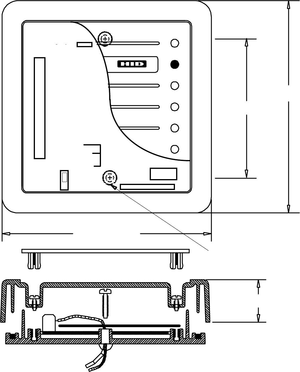
1. Determine an appropriate mounting position for the reader. The reader drawing below is actual size and
may be used as a template. Install a single or double gang electrical box or drill the appropriate mounting
for #6 fasteners. If mounting to a metal surface, drill two 7/64 (.109) inch holes and use the enclosed self
tapping screws for mounting.
2. Route the interface cable from the reader and/or power supply to the Host.
3. Prepare the cable by cutting the cable jacket back 2 (two) inches and strip the wires 1/4 inch. Tinning the
wires is not required.
4. Pry off the center face plate by placing a thin blade into the grove that outlines the face of the reader. Use
care to avoid scratching the surface of the reader. The face plate is attached to the reader by friction
only. The screws that hold the enclosure pieces together will be exposed. Loosen the four screws to open
the enclosure (the enclosure screws are captive to the cover).
5. Install the cable fitting on the rear of the reader. Feed the cable through the cable fitting, tighten the fitting
nut so the cable jacket is flush with the printed circuit board. Dress the cable conductors and connect the
reader to the Host according to the terminal descriptions in the dimension diagram and wiring table. The
____________________________________________________________________________________________
HID Corporation 9292 Jeronimo Road Irvine, CA 92618 USA TEL (949) 598-1600 (800) 237-7769 FAX (949) 598-1690
Web page, E-mail -www.hidcorp.com ProxPro Reader Installation Manual 5355A-900 Rev M 3 of 11
descriptions are on the PCB guard in the reader. Connect the drain line of the shield to terminal 2 (Power
Supply Ground). Terminal 5, Data Return, is to be connected to the ground of the Host if the power supply
ground is not common with the Host. The opposite end of the drain line should be cut flush with the jacket
and left disconnected.
6. If the tamper feature is available on the Host, connect the tamper switch using the connections
recommended by the Host documentation. The switch is a single pole, double throw. When the inner reader
cover is removed, the tamper switch is released. The TB1 connections to the tamper switch are pins 10 and
11. Pin 10 is the common contact of the switch and pin 11 is either the normally open or closed. Jumper P3
selects the contact of the tamper switch, either the normally closed or the normally open contact. The
default position is P3 across pins 1 and 2. This selects the normally open contact on TB1 pin 11. If the
normally closed contact is required, move P3 across pins 2 and 3. (Note - “normally open and normally
closed refer to the Pin 11 status while the cover is removed.) The contacts are rated for 100mA at 35 VDC.
7. Mount the base of the reader that holds the electronics to the gang box or surface using the two holes
located on the center axis of the reader. Two #6-32 x 1 inch screws are provided for mounting to a gang
box or metal surface.
8. Set the DIP switches according to the table in the section, DIP Switch Settings.
9. Place the jumper on P1 between pins 1 and 2 when mounting to a metallic surface or to a junction box
with a metal cover plate. Otherwise, the jumper should be between pins 2 and 3, the default position.
10. After wiring the Reader and power supply, the Reader is ready to be tested. Power up the Reader and the
LED and Beeper will flash and beep 3 times in a sequence of two short delays and one long delay. This
indicates that the micro-controller unit is working properly. If the switches have been set for external control
only, the Reader will 3 shorts and a long. Present an ID card to the Reader and the LED should momentarily
turn green, indicating a read of the card. If the Reader LED is controlled by the Host refer to the Host
description of the LED operation.
11.
Replace the top cover and face plate.
Standard Wire Connections
TB1
12345678910 11
+DC Ground Data0/
Data Data1/
Clock Shield
Ground Green
LED Red
LED Beeper Hold/
Card
Present
Tamper
Common Tamper
Select
Red Black Green White Violet Orange Brown Yellow Blue -- --
Buffered Direct Wire Connections – Option D
10 11 E1 E2 E3 E4 E5 E6 E7 E8 E9 E10
Tamper
Common Tamper
Select +DC Ground Row 1 Row 2 Row 3 Row 4 Column
1Column
2Column
3Select
Low
Red /
Black Red /
Green White /
Red White /
Black Gray Violet Red /
Yellow Pink Tan White /
Blue White /
Green White /
Yellow
Direct Wire Connections – Option S
TB2
1234567
Row 1 Row 2 Row 3 Row 4 Column
3Column
2Column
1
Red Black Green White Drain Orange Brown
____________________________________________________________________________________________
HID Corporation 9292 Jeronimo Road Irvine, CA 92618 USA TEL (949) 598-1600 (800) 237-7769 FAX (949) 598-1690
Web page, E-mail -www.hidcorp.com ProxPro Reader Installation Manual 5355A-900 Rev M 4 of 11
Cable Notes:
1) When using 5 conductor cable, the power supply and Host must have a common ground (voltage
reference).
2) 6 conductor cable is required when controlling the red and green LED. (Alpha 1296 C or equivalent)
3) 7 conductor cable is required when both green and red LED’s are controlled by the Host and the power
supply and Host "ground" are separate. (Alpha 1297 C or equivalent)
4) A 22 AWG twisted pair, shielded, stranded cable is often required for the tamper switch. Follow the
recommendations of the manufacturer of the Host system. If the tamper input is a supervised input the "end
of line" resistors may be mounted in the enclosure. Use extreme care and shield any bare wire from the
printed circuit assembly and its components.
5) The inner diameter of the cable fitting will accommodate a cable with an outer diameter of .300 inches
(nominally).
6) Connect cable shield by connecting drain wire to TB1-2 ground. Leave foil and drain wire disconnected at
host end of cable by cutting them off at the end of the cable jacket.
7) When using the Buffered Direct Connect ProxPro with a 20 conductor cable, DC+ and Power (Red and
White / Red wires) must have a common connection to the host +DC power supply. The two ground wires
(Black and White / Black) must have a common ground connection to the host +DC power supply.
____________________________________________________________________________________________
HID Corporation 9292 Jeronimo Road Irvine, CA 92618 USA TEL (949) 598-1600 (800) 237-7769 FAX (949) 598-1690
Web page, E-mail -www.hidcorp.com ProxPro Reader Installation Manual 5355A-900 Rev M 5 of 11
5.00" (127mm)
3.28" (83.3mm)
5.00" (127mm)
1.00" (25.4mm)
O
O
O
O
O
O
O
O
O
O
TB1
2 - GND
3 - DATA "0"
4 - DATA "1"
5 - DATA RTN
1 - DC +
TAMPER SW SW1
P1
P2
mounting holes (2 places)
Dimension Drawin
g
(
Actual Size
)
7 - Red LED
6 - Green LED
8 - Beeper
9 - Hold
1 - n/o
3 - n/c
10 - COM
O 11 - Tamper
123
DIP Switch Settings - Switch 1

____________________________________________________________________________________________
HID Corporation 9292 Jeronimo Road Irvine, CA 92618 USA TEL (949) 598-1600 (800) 237-7769 FAX (949) 598-1690
Web page, E-mail -www.hidcorp.com ProxPro Reader Installation Manual 5355A-900 Rev M 6 of 11
Switch 1-1 Hardware Identity
When set in the "on" position the unit is configured for "Wiegand" interface. The "off" position configures the unit
for "Clock and data" interface.
Switch 1-2 Audible Tone Control
The Audible Tone (Beeper) may be enabled or disabled to sound when an access card is read. When enabled,
the audible tone is sounded when the a card is successfully read. When the Beeper is disabled, the only
method to activate the Beeper is to use the external Beeper control line. The Beeper will turn on when the
control line is switched to ground. Switch 2 in the "on" position enables the audible tone (the default).
Switch 1-3 Green LED Control
The Green LED can be configured to turn on, or not turn on when an access card is read. Switch 3 in the “off”
position selects the Green LED to be turned on (the default).
Switch 1-4 Keypad Operation
The keypad inputs may be processed by the reader or may be connected directly to the Host. When the
keypad inputs are processed by the reader, the reader scans the keypad and outputs the keypad entries over
the "Wiegand" interface. When the keypad is connected to the Host, the Host determines which key is being
entered. Switch 4 is in the "on" position for the default mode (the keypad inputs are processed by the reader).
Switch 1-5 Single / Dual LED Control
In Single LED Control the LED is Red. When an access card is read, the LED toggles Green, and then back to
Red. Grounding the Green LED Control line will change the LED from Red to Green. The reader maybe
configured so the Green LED is externally controlled independently from the Red LED. This is referred to as
Dual LED Control. When the Red or Green LED Control line is switched to ground, the respective LED is
turned on. If both LED’s are on, the LED appears to glow amber. Switch 5 in the “off” position selects Single
LED Control (the default).
Switch 1-6 and 1-7 Data Output Biasing
The data outputs may be configured as open collector or biased at 5VDC through 1k Ohm resistors by the
reader. The default (standard) configuration is output biasing, with switches 6 and 7 "on" . Note: When the
outputs are configured as open collector, the host panel should provide bias voltage at the panel inputs.
KeyPad
Beeper Control
Hardware Identity
on
Default Setting
on
on
on
on
on
on
off
(The keypad data is sent on data lines), N/A for D version
(Identifies the unit to be "Wiegand")
12345678
Single/Dual LED CNTL
(Single Line LED Control)
off
Green LED Control
Not used
(The Wiegand data outputs are pulled up to +5VDC
through a 1kOhm resistor)
(The green LED is enabled when a card is read)
( The beeper is enabled when a card is read)
Wiegand Data 0 Bias
Wiegand Data 1 Bias
Keypad Option Notes:
This section of this document describes the keypad interface. The keypad has twelve keys, four rows by three
columns. The characters 0 to 9, # and * are arranged the same as a standard telephone keypad. There are two
methods for interfacing to the Keypad.
The first configuration (K version, internal keypad) processes the keypad entries in the reader and then
transmits the data to the host system via the Wiegand data lines. The reader outputs each key as an ASCII
encoded hexadecimal digit. The decoding of the message sent through the Wiegand interface is the only
____________________________________________________________________________________________
HID Corporation 9292 Jeronimo Road Irvine, CA 92618 USA TEL (949) 598-1600 (800) 237-7769 FAX (949) 598-1690
Web page, E-mail -www.hidcorp.com ProxPro Reader Installation Manual 5355A-900 Rev M 7 of 11
processing required of the host system. The user interface has been implemented in the most generic fashion
to give the integrator the most flexibility.
The Second configuration (S version, direct connect keypad), the host must scan the keypad directly using a
separate cable.
K Version - Internal keypad processing
Parity and Length options must be factory configured. Contact customer service to enable these options.
Parity Option
The default does not included parity in the data message. When the parity option is enabled, parity is added to
the total message independent of length. The parity coverage is diagrammed below. Each parity bit covers
exactly one half of the message.
P XXXXXXXX......XXXXXXXXP
EXXXXXXXX......XXXXXXXXP
Length Buffer keys) Option
The length option chooses the number of key entries that will be buffered before the message is sent to the
host. The maximum number of entries is 10 with parity and 11 without parity. When the option is set for
multiple entries the reader has a five (5) second timer that will clear all entries after five seconds has expired
between entries. The length option requires the user to enter the programmed number of key entries. Upon
completion of the last key entry, the message is assembled and sent. Parity is added if the option is set. This
requires the system integrator to configure the reader for the number of key entries before installation.
User Interface
The user is able to press keys at any time. Card reads and key entries are independent of each other, the
user is not required to follow any sequence, unless specified by the system integrator. The reader is equipped
to give the user audible, visual and tactile feedback when a key is pressed. The amount of time is 5 (five)
seconds between key entries when the multiple key entry option is used. If the time expires between key
entries, all keys entered are cleared and the user must start the sequence from the beginning.
Keypad Message
The keypad message follows a basic format. The entries are transmitted in the hexadecimal representation.
When parity is added, the message format mimics the "standard 26 bit Wiegand format" . The key that is
pressed is represented in Hexadecimal with * represented by A (HEX) and # represented by B (HEX).
0 = 0000 4 = 0100 8 = 1000
1 = 0001 5 = 0101 9 = 1001
2 = 0010 6 = 0110 * = 1010
3 = 0011 7 = 0111 # = 1011
Example: without parity:
AAAA BBBB CCCC DDDD ..... KKKK
AAAA = The first key entered
BBBB = The second key entered
KKKK = The eleventh key entered (the maximum)
Example: with parity:
A message that has a fixed number of key entries set to 4 and the parity option included.
P AAAA BBBB CCCC DDDD P
A - the first key entered
B - the second key entered
C - the third key entered
D - the fourth key entered
P - Parity Bits.

____________________________________________________________________________________________
HID Corporation 9292 Jeronimo Road Irvine, CA 92618 USA TEL (949) 598-1600 (800) 237-7769 FAX (949) 598-1690
Web page, E-mail -www.hidcorp.com ProxPro Reader Installation Manual 5355A-900 Rev M 8 of 11
The whole message is similar to the "Standard 26 Bit Wiegand" formatted message. The format consists of
two parity bits at the opposite ends, one odd and the other even. Each parity bit covering exactly one half of
the message.
P XXXXXXXX......XXXXXXXXP
EXXXXXXXX......XXXXXXXXP
Keypad Scanning 2 of 7 (K version)
This mode requires a separate cable to be supplied that connects to the Keypad board, inside the ProxPro, to
the Host via P2. P2 is a 7 position terminal strip. Switch 1-4 (SW1-4) should be switched to the “off” position.
The reader will then NOT process the keypad data, and it will be decoded by the host in 2 of 7 format.
The keypad has a matrix of contacts corresponding with the matrix of keys. The contact outputs are wired to
the seven terminals of P2. The seven terminals are called P2-1 thru P2-7 and provide the 2 of 7 decode of the
buttons. When a key is pressed, the button closes two contacts that pull 2 lines to ground. This results of the
key entries are in the table below. The reader and the host that is scanning the keypad will require a common
signal ground. The connection is to be made on either pin 2 (power supply ground) or 5 (Data Return) of TB1 of
the ProxPro.
This method of interfacing the keypad requires additional processing by the host. These include the de-bouncing
of the keys, decoding of the keypad, timing between key entries, as well as others depending on the Host. The
2 of 7 format is available on the ProxPro 5355XXKXX versions.
Key Pad Data Table - 2 of 7
Key # Terminal Number
P2-1 P2-2 P2-3 P2-4 P2-5 P2-6 P2-7
1LOHIHIHIHIHILO
2LOHIHIHIHILOHI
3LOHIHIHILOHIHI
4 HILOHIHIHIHILO
5 HILOHIHIHILOHI
6 HILOHI HILOHIHI
7 HIHILOHI HI HILO
8 HIHILOHI HILOHI
9 HIHILOHILOHIHI
* HIHI HILOHI HILO
0 HIHI HILOHILOHI
# HIHI HILOLOHIHI
HI represents a voltage of +5 volts in reference to the ProxPro ground.
LO represents the ProxPro ground.
Note: The system is to be used on a single point ground system.
S Version - Direct connect keypad Scanning - 3 X 4 Matrix format
The ProxPro reader is available with a 3 x 4 matrix keypad. The keypad is independent of the ProxPro reader
and only provides the connections to the keypad. This mode requires a separate cable to be supplied that
connects to the Keypad board, inside the ProxPro, to the Host via P2. P2 is a 7 position terminal strip. The
following is the table for the contact closures.
____________________________________________________________________________________________
HID Corporation 9292 Jeronimo Road Irvine, CA 92618 USA TEL (949) 598-1600 (800) 237-7769 FAX (949) 598-1690
Web page, E-mail -www.hidcorp.com ProxPro Reader Installation Manual 5355A-900 Rev M 9 of 11
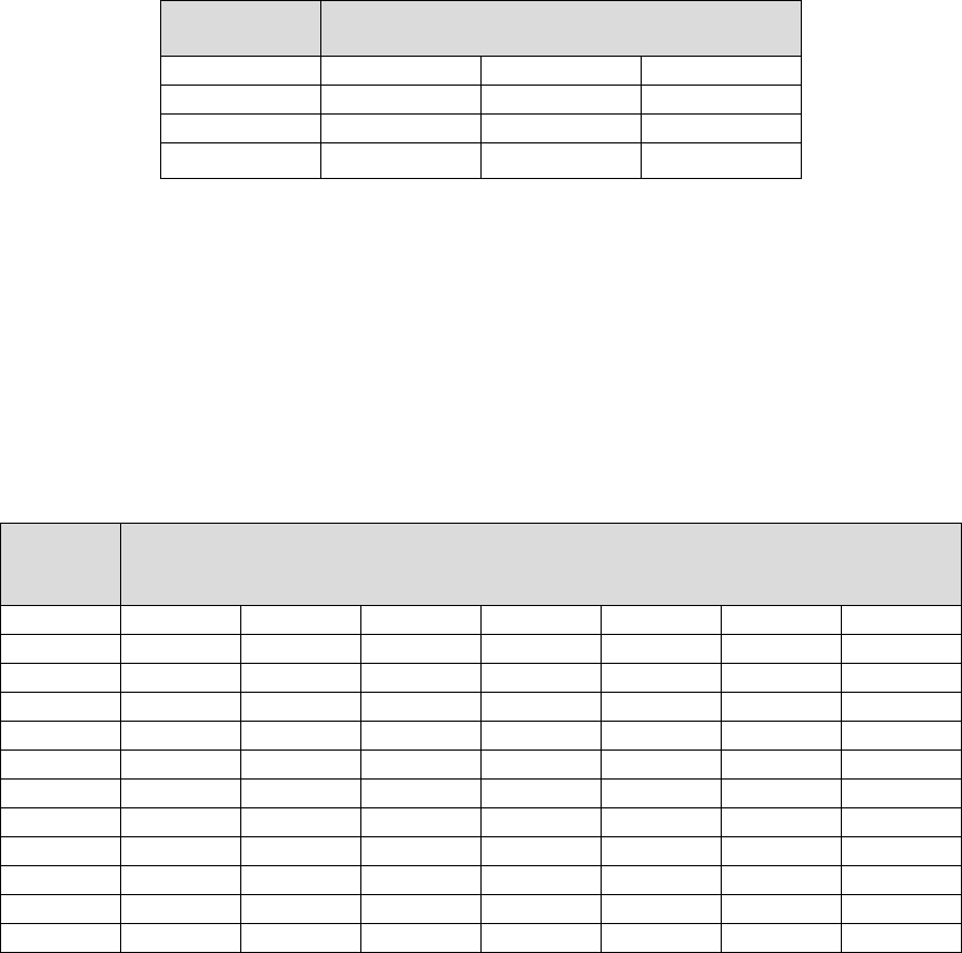
This table indicates the connection between the connector pins when a key is pressed. For example, if key 3 is
pressed P2-5 is connected (shorted) to P2-1. This is available on the Serial ProxPro 5355XXSXX versions.
Rows Columns
P2-5 P2-6 P2-7
P2-1321
P2-2654
P2-3987
P2-4 # 0 *
D Version – Bufferd Direct connect keypad Scanning - 3 X 4 Matrix format
The ProxPro reader is available with a 3 x 4 matrix keypad. The keypad is independent of the ProxPro reader
and only provides a voltage output from the keypad. This mode requires a separate cable to be supplied that
connects to the Keypad wiring to the host. This method of interfacing the keypad requires additional processing
by the host. This includes toggling the select low line to ground to enable the keypad, debouncing of the keys,
decoding of the keypad voltages, timing between key entries, as well as others depending on the host.
This table indicates the voltage on the keypad wires when a key is pressed. This is available on the Buffered
Direct Connect ProxPro 5355XXDXX versions.
Buffered Direct Connect KeyPad Data Table
Wire Colors
Key # Gray Violet Red /
Yellow Pink Tan White /
Blue White /
Green
1 LOHI HI HILOHI HI
2LOHIHIHIHILOHI
3LOHIHIHIHIHILO
4 HILOHI HILOHI HI
5 HILOHI HI HILOHI
6 HILOHIHIHIHILO
7 HI HILOHILOHI HI
8 HI HILOHI HILOHI
9 HIHILOHIHIHILO
* HIHIHILOLOHIHI
0 HI HI HILOHILOHI
# HIHIHILOHIHILO
HI represents a voltage of +5 volts in reference to the ProxPro ground.
LO represents the ProxPro ground.
Notes:
1) The system is to be used on a single point ground system.
2) On the Buffered Direct Connect toggle Select Low (White/Yellow) wire to ground to enable the above
keypad outputs.

____________________________________________________________________________________________
HID Corporation 9292 Jeronimo Road Irvine, CA 92618 USA TEL (949) 598-1600 (800) 237-7769 FAX (949) 598-1690
Web page, E-mail -www.hidcorp.com ProxPro Reader Installation Manual 5355A-900 Rev M 10 of 11
ProxPro Reader™ Specifications
Read Distance - using ProxCard II
! Over all Operating Limits, minimum (@12VDC)) 5.0 inches (12.7 cm)
! Non-Metallic Mounting, typical (@12VDC) 8.0 inches (20.3 cm)
! Mounted on Metal, typical (@12VDC) 5.5 inches (14 cm)
! Overall Operating Limits, minimum (@24VDC) 5.5 inches (14 cm)
! Non-Metallic Mounting, typical (@24VDC) 9.0 inches (23 cm)
! Mounted on Metal, typical (@24VDC) 6.0 inches (15.2 cm)
Environmental Characteristics
! Designed for listing under UL 294 “Standard for Access Control System Units”
! Operating Temperature Range -30oC to 65oC (-22oF to 150oF)
! Storage Temperature Range -40oC to 85oC (-40oF to 185oF)
! Operating Humidity Range 5% to 95% non-condensing
! Operating Vibration Limit .04 g2/Hz 20-2000Hz
! Operating Shock Limit 30g, 11mS, Half Sine
! Enclosure Material UL Recognized Lexan Polycarbonate
! Weight 11.3oz (310gms)
Power Requirements
! Power supply Linear type recommended
! Operating Voltage Range (+DC) 10VDC -28.5VDC
! Maximum Average Current 12V/24V 90mA/155mA
! Transient Protection (all terminals) UL 294
! Reverse Voltage Protection YES
! Input Voltage (maximum data-0/1 lines) 28.5VDC
! Input Voltage (maximum interface lines) 28.5VDC
Option D – Buffered Direct Connect Keypad
! Operating Voltage Range (+DC) 10VDC -26VDC
! Input Voltage (Maximum Data – 0/1 Lines) 14VDC
! Input Voltage (Maximum Interface Lines) 14VDC
Operating Parameters
! Excitation Frequency 125KHz
! Duty Cycle (alternate power level rate) 20% @ 60mS period
! Read and Report Speed (26 bit Wiegand Card) 175mS
! Maximum Cable Distance to Host 500 feet (152 meters)
! LED Type Bi-colored Red/Green
! LED Operation (host control of red/green) <.5V on LED control line
! Beeper Operation (host control) <.5V on beeper line
! LED Control (default) internal/single
! Beeper Control (default) Beeper enabled
! Anti-Pass Back Delay (default) 1 second
! Wiegand Data Pulse Widths (default) 40uS
! Wiegand Data Interval (default) 2mS
! Clock/Data bit time 1.5ms (default)
! Clock/Data strobe width bit time/3 (33% of bit time), default = 500us
! Clock/Data clock/strobe is valid 1.5ms (one clock cycle, min) after card present is
! Asserted data is valid 10us (min) before the
! negative edge of clock/strobe
card present returns to the high level 50 ms
(max)
after the last clock/strobe.

____________________________________________________________________________________________
HID Corporation 9292 Jeronimo Road Irvine, CA 92618 USA TEL (949) 598-1600 (800) 237-7769 FAX (949) 598-1690
Web page, E-mail -www.hidcorp.com ProxPro Reader Installation Manual 5355A-900 Rev M 11 of 11
Product Configuration/Ordering Options
5355 A G N 00 -XXXX Y Customer Custom Artwork or Firmware Number
1 through 9, A through Z
Customer Custom Number
Configuration Options - (00 standard)
Standard Hardware Options - N = None, K = Standard Keypad (internal or
2 of 7), S = Direct Connect Keypad (3 x 4 type), D = Buffered Direct Connect
Keypad (3 x 4 type)
Color - G = Gray, B = Beige
Model Number Suffix
Model Number 5355 = ProxPro Wiegand
Model Number 5358 = ProxPro Clock/Data
Final Assembly Number = 5355-300-XX Changes with Revisions
NOTES: THE ABOVE ARE RECOMMENDED INSTALLATION PROCEDURES. ALL LOCAL, STATE AND
NATIONAL ELECTRICAL CODES TAKE PRECEDENCE.