HID Global 537Y Identification Proximity Reader User Manual
HID Global Corporation Identification Proximity Reader
UserManual.wiki
>
HID Global
>
537Y User Manual
User manual
Navigation menu
Upload a User Manual
Namespaces
Wiki Guide
HTML
PDF
Info
Views
User Manual
Discussion / Help
Navigation
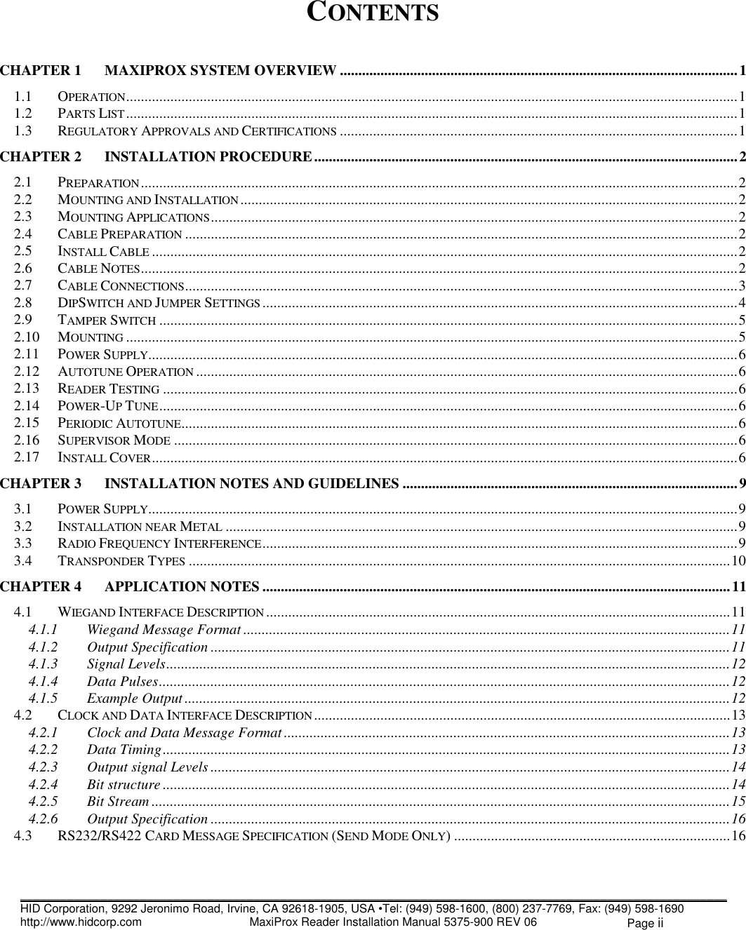
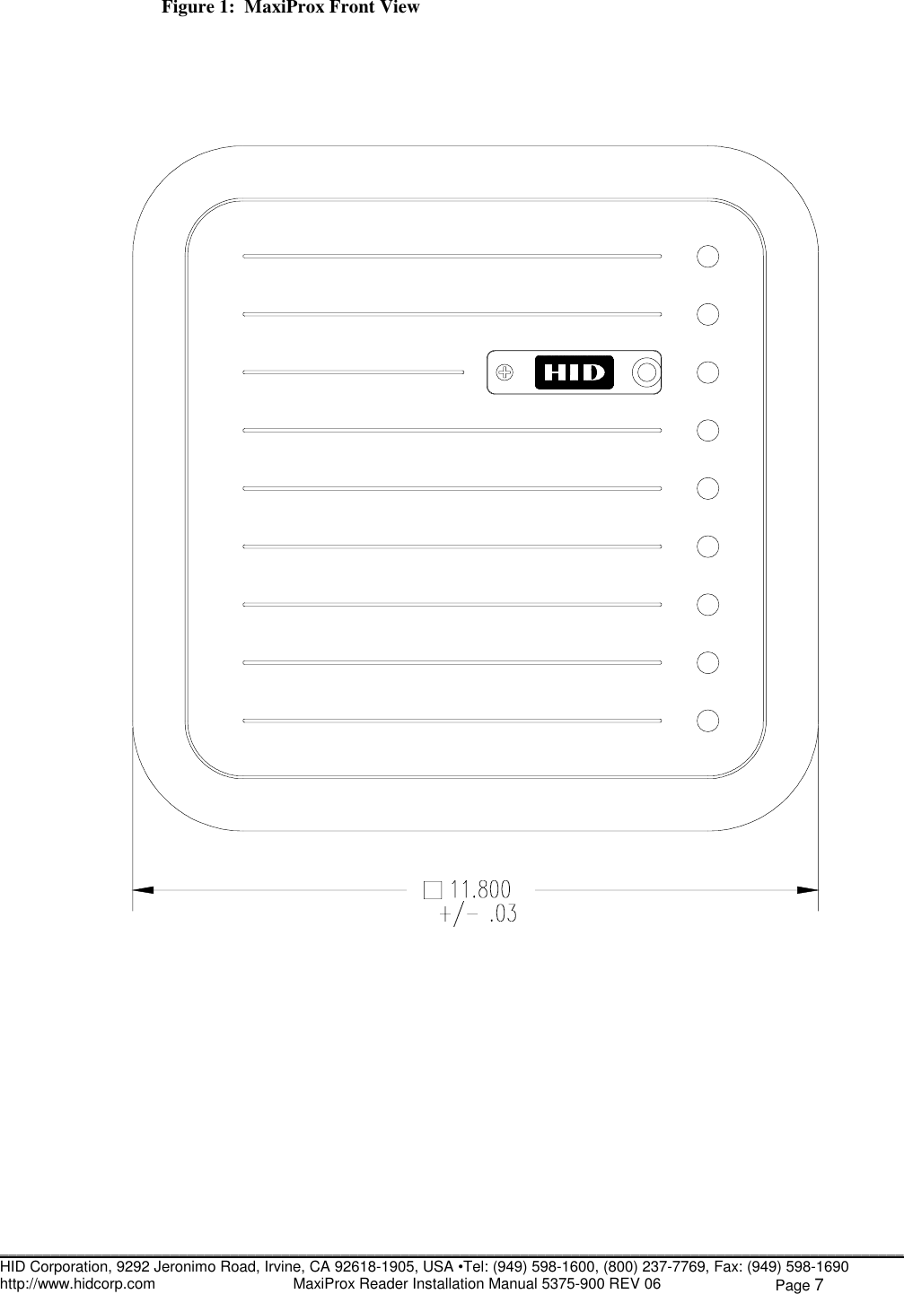
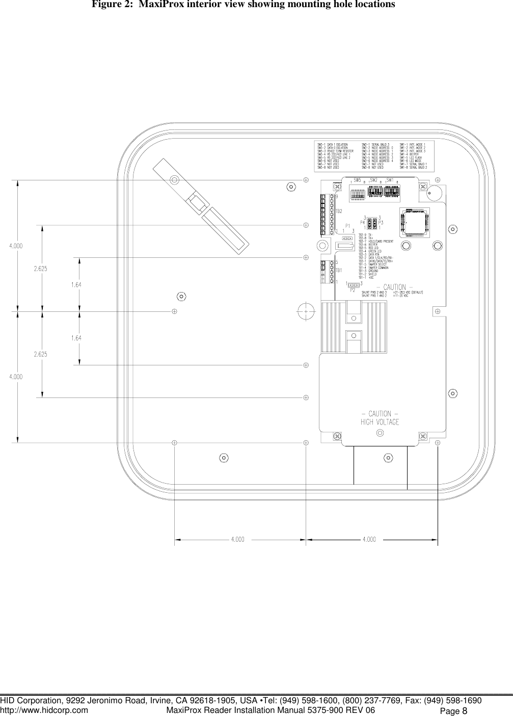
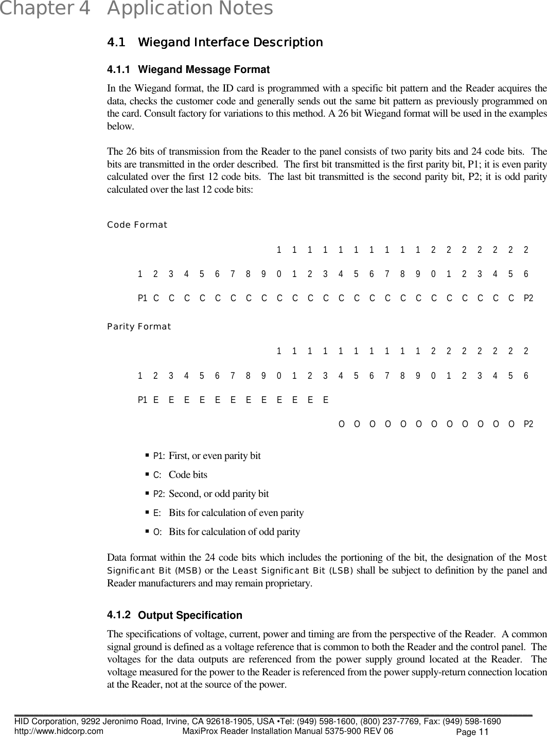
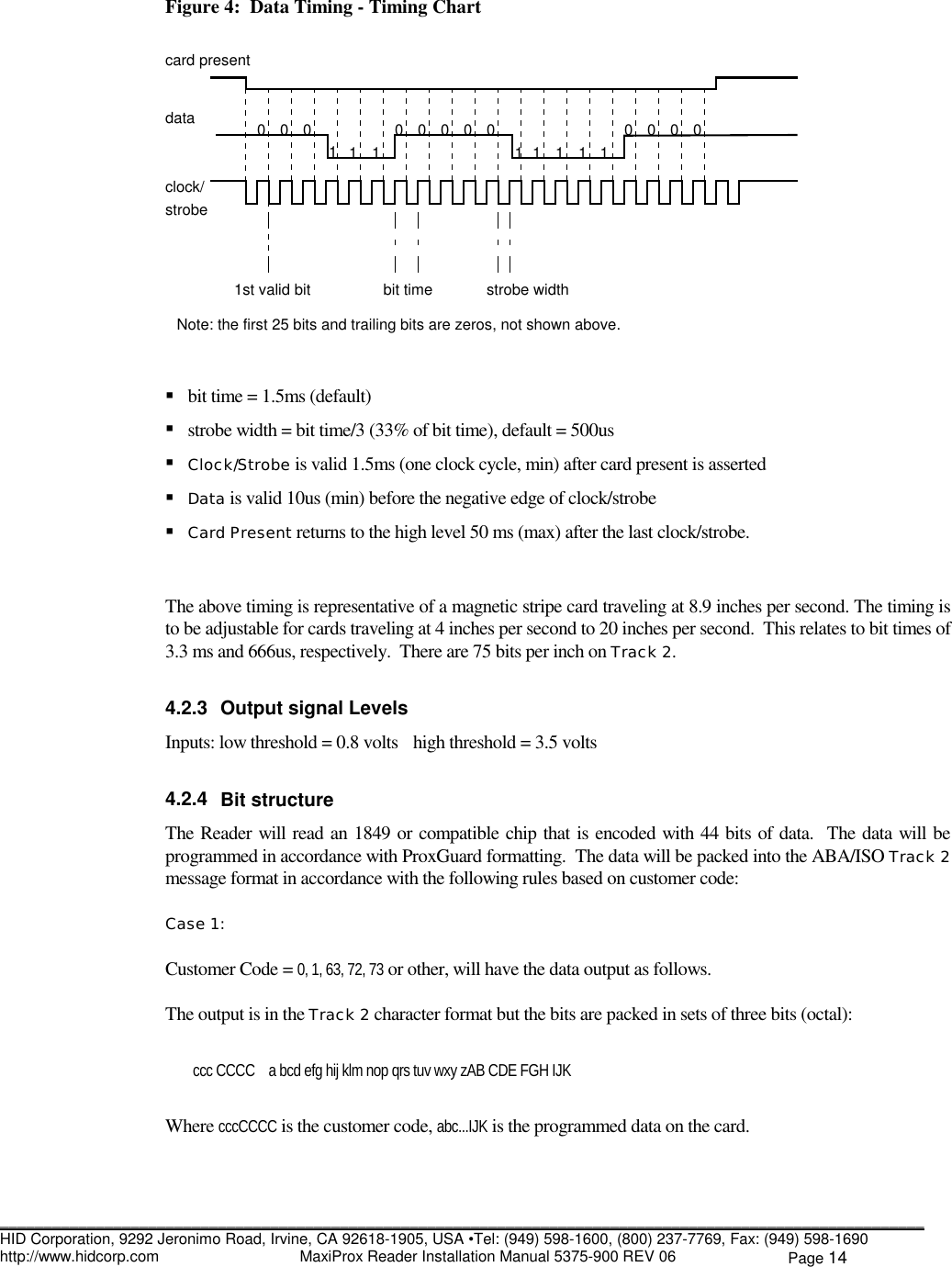
![__________________________________________________________________________________________________________HID Corporation, 9292 Jeronimo Road, Irvine, CA 92618-1905, USA •Tel: (949) 598-1600, (800) 237-7769, Fax: (949) 598-1690http://www.hidcorp.com MaxiProx Reader Installation Manual 5375-900 REV 06 Page 13NoteThe customer code is never transmitted or displayed.4.2 4.2 4.2 4.2 Clock and Data Interface DescriptionClock and Data Interface DescriptionClock and Data Interface DescriptionClock and Data Interface Description4.2.1 Clock and Data Message FormatThe Clock and Data interface consists of three signals, Card Present, Data and Strobe/Clock. The interface isa serial data stream, which is controlled with a clock/strobe that indicates when data is valid. All signals arequiescent high. Card Present goes low when data is about to be sent and remains low until the whole datastream is completed. Data is the signal that determines the “ones” and “zeros”. Strobe/Clock is the signalthat indicates when data is valid for each cycle.The Track 2 message format is a stream of binary bits that are grouped into HEX characters. The messagestarts with leading zeros, followed by a start sentinel, data, end sentinel, LRC and trailing zeros. Each HEXcharacter has error correction in the form of a parity bit. Each character consists of five bits. The maximumnumber of characters for a magnetic strip card encoded on Track 2 are 40, this product will output less than40 characters. The data consists only of BCD digits, the remaining HEX digits, A to F, are used for the startand end sentinel, data separators and control. Only hex B and F are used, A, C D and E are not used. Themessage will consist of a minimum of 210 bits.The bits of a character are in the order 1248P, where parity is odd over the four bits. The LRC is the Xoringof the message, starting with the start sentinel and ending with the end sentinel. The LRC does not includethe parity bits of the characters in the Xoring. LRC does include its own odd parity bit that covers the fourbits that are the result of the Xoring.<leading zeros><Start Sentinel><data><data>........<data><End sentinel><LRC><trailing zero>Customer code 0,1, 63, 72 and 73 (existing customer codes) cards will be read and output in the Track 2format. The data on these cards will be packed into the Track 2 format in segments of three bits, so thecharacter does not exceed a BCD seven.4.2.2 Data TimingThe outputs, Card Present, Data and Strobe are low going signals and the following timing chart describesthe timing.sentinel parity paritycustomer code 10 zeros bit even facility code card number odd[0 0 0 0 0 0 1] [0 0 0 0 0 0 0 0 0 0] [1] [0] [0 1 1 0 0 1 0 1] [0 0 0 0 0 0 1 1 0 0 1 1 0 0 0 0] [1]| 0 | 2 | 0 | 0 | 4 | C | A | 0 | 6 | 6 | 1 |Wiegand Output | 0 | C | A | 0 | 6 | 6 | 1 |Hex code numbers [ 6 | 5 ][ 0 | 3 | 3 | 0 ]Decimal conversion [ 101 ][ 0816 ]](https://usermanual.wiki/HID-Global/537Y/User-Guide-62884-Page-16.png)