HID Global 537Y Identification Proximity Reader User Manual
HID Global Corporation Identification Proximity Reader
User manual

__________________________________________________________________________________________________________
HID Corporation, 9292 Jeronimo Road, Irvine, CA 92618-1905, USA •Tel: (949) 598-1600, (800) 237-7769, Fax: (949) 598-1690
http://www.hidcorp.com MaxiProx Reader Installation Manual 5375-900 REV 06 Page i
Installation Manual - 5375-900 Rev 06
MaxiProx Reader 5375A

__________________________________________________________________________________________________________
HID Corporation, 9292 Jeronimo Road, Irvine, CA 92618-1905, USA •Tel: (949) 598-1600, (800) 237-7769, Fax: (949) 598-1690
http://www.hidcorp.com MaxiProx Reader Installation Manual 5375-900 REV 06 Page ii
CONTENTS
CHAPTER 1 MAXIPROX SYSTEM OVERVIEW ............................................................................................................1
1.1 OPERATION......................................................................................................................................................................1
1.2 PARTS LIST ......................................................................................................................................................................1
1.3 REGULATORY APPROVALS AND CERTIFICATIONS ............................................................................................................1
CHAPTER 2 INSTALLATION PROCEDURE...................................................................................................................2
2.1 PREPARATION..................................................................................................................................................................2
2.2 MOUNTING AND INSTALLATION .......................................................................................................................................2
2.3 MOUNTING APPLICATIONS...............................................................................................................................................2
2.4 CABLE PREPARATION ......................................................................................................................................................2
2.5 INSTALL CABLE ...............................................................................................................................................................2
2.6 CABLE NOTES..................................................................................................................................................................2
2.7 CABLE CONNECTIONS......................................................................................................................................................3
2.8 DIPSWITCH AND JUMPER SETTINGS .................................................................................................................................4
2.9 TAMPER SWITCH .............................................................................................................................................................5
2.10 MOUNTING ......................................................................................................................................................................5
2.11 POWER SUPPLY................................................................................................................................................................6
2.12 AUTOTUNE OPERATION ...................................................................................................................................................6
2.13 READER TESTING ............................................................................................................................................................6
2.14 POWER-UP TUNE.............................................................................................................................................................6
2.15 PERIODIC AUTOTUNE.......................................................................................................................................................6
2.16 SUPERVISOR MODE .........................................................................................................................................................6
2.17 INSTALL COVER...............................................................................................................................................................6
CHAPTER 3 INSTALLATION NOTES AND GUIDELINES ...........................................................................................9
3.1 POWER SUPPLY................................................................................................................................................................9
3.2 INSTALLATION NEAR METAL ...........................................................................................................................................9
3.3 RADIO FREQUENCY INTERFERENCE.................................................................................................................................9
3.4 TRANSPONDER TYPES ...................................................................................................................................................10
CHAPTER 4 APPLICATION NOTES ...............................................................................................................................11
4.1 WIEGAND INTERFACE DESCRIPTION ..............................................................................................................................11
4.1.1 Wiegand Message Format ....................................................................................................................................11
4.1.2 Output Specification .............................................................................................................................................11
4.1.3 Signal Levels.........................................................................................................................................................12
4.1.4 Data Pulses...........................................................................................................................................................12
4.1.5 Example Output ....................................................................................................................................................12
4.2 CLOCK AND DATA INTERFACE DESCRIPTION.................................................................................................................13
4.2.1 Clock and Data Message Format .........................................................................................................................13
4.2.2 Data Timing..........................................................................................................................................................13
4.2.3 Output signal Levels .............................................................................................................................................14
4.2.4 Bit structure..........................................................................................................................................................14
4.2.5 Bit Stream .............................................................................................................................................................15
4.2.6 Output Specification .............................................................................................................................................16
4.3 RS232/RS422 CARD MESSAGE SPECIFICATION (SEND MODE ONLY) ...........................................................................16

__________________________________________________________________________________________________________
HID Corporation, 9292 Jeronimo Road, Irvine, CA 92618-1905, USA •Tel: (949) 598-1600, (800) 237-7769, Fax: (949) 598-1690
http://www.hidcorp.com MaxiProx Reader Installation Manual 5375-900 REV 06 Page iii
FIGURES
FIGURE 1: MAXIPROX FRONT VIEW ...............................................................................................................................................7
FIGURE 2: MAXIPROX INSIDE VIEW SHOWING MOUNTING HOLE LOCATIONS ...................................................................................8
FIGURE 3: DATA PULSES - TIMING PARAMETERS .........................................................................................................................12
FIGURE 4: DATA TIMING - TIMING CHART....................................................................................................................................14
TABLES
TABLE 1: TB1 CONNECTOR DEFINITION ........................................................................................................................................3
TABLE 2: TB2 CONNECTOR DEFINITION ........................................................................................................................................3
TABLE 3: DIPSWITCH AND JUMPER SETTINGS ...............................................................................................................................4
TABLE 4: INTERFACE JUMPERS DESCRIPTION - P3 AND P4.............................................................................................................4
TABLE 5: SWITCH DESCRIPTION - SW2..........................................................................................................................................4
TABLE 6: MODE CHART .................................................................................................................................................................4
TABLE 7: BAUD RATE CHART – RS232 AND RS422 ......................................................................................................................4
TABLE 8: SWITCH DESCRIPTION - SW5..........................................................................................................................................5
TABLE 9: LOGIC LEVELS ..............................................................................................................................................................12

__________________________________________________________________________________________________________
HID Corporation, 9292 Jeronimo Road, Irvine, CA 92618-1905, USA •Tel: (949) 598-1600, (800) 237-7769, Fax: (949) 598-1690
http://www.hidcorp.com MaxiProx Reader Installation Manual 5375-900 REV 06 Page 1
Chapter 1 MaxiProx System Overview
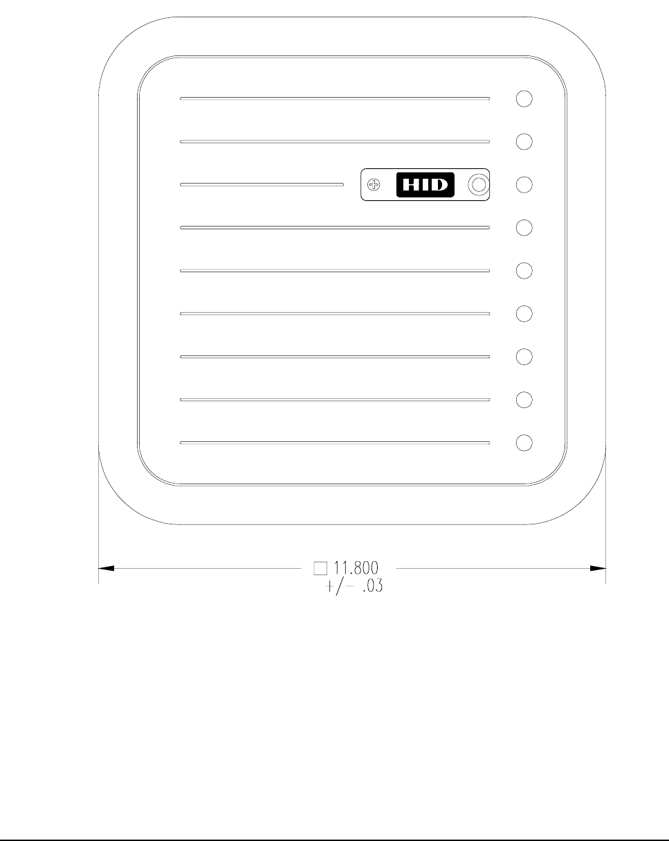
The MaxiProx Reader is a self-contained proximity Reader. The two piece polycarbonate enclosure has an
O-ring that weather seals the enclosure pieces together and a cable fitting that seals the cable entry. The
water-resistant unit is designed for outdoor use. The enclosure is mountable on a single gang electrical box.
A bi-color LED and audible tone provide user feedback. Configurable open collector data outputs provide
the data to the Host. Configurable DIPswitches and jumpers provide choice of data interfaces between
Wiegand, Clock and Data, RS 232 and RS422. The data interface is configured as ordered from the factory,
but can be changed in the field - please contact HID Technical Support for assistance. A tamper switch can
alert the Host when the enclosure is opened. Internal DIP switches and jumpers provide for configuration of
the outputs, audible tone and LED control options. Installation of the MaxiProx Reader consists of
mounting, connecting the cable to the Host and +12VDC or +24VDC power, verifying the DIPswitch and
jumper settings, verifying Autotune, and verifying the reading of a transponder.
1.1
1.1 1.1
1.1 Operation
OperationOperation
Operation
Transponders (Proximity Cards or ProxKeys) are presented to the front of the MaxiProx. The LED is red
when ready to read a transponder. The LED turns green and the beeper sounds when the transponder is read
and the message is transmitted to the Host computer or interface panel. The system is ready for another
transponder as soon as the LED returns to red. There is an anti-passback delay of about one and a half
seconds before it will read the same card. The LED flash is typically 250 milliseconds long. The operation of
the LED and beeper may be controlled by the Host, in which case the actual operation will depend on the
programmed timing of the Host.
1.2
1.2 1.2
1.2 Parts List
Parts ListParts List
Parts List
1. MaxiProx Reader Qty 1 (included)
2. Installation Manual Qty 1 (included)
3. Cable Fitting Qty 1 (included)
4. Label for front cover - HID logo Qty 1 (included)
5. #6-32 x 1" flat head screw, for upper-left base mount screw Qty 1 (included)
6. #6-32 x 1" black screw, for gang-box mounting Qty 2 (included)
7. #6-32 x .75" flat head screw, for front cover mounting Qty 1 (included)
8. Cable, 5 conductor, 22 AWG (Alpha 1295 C or equivalent) See cable notes
9. Power Supply – 2.0 A linear regulated +24VDC, nominal (+21 to +28.5VDC)
Factory Default – No P2 Shunt Jumper
10. +12VDC Shunt Jumper – P2-1 to P2-2 for 12VDC operation +12VDC, nominal (+11VDC to +20VDC)
1.3
1.3 1.3
1.3 Regulatory Approvals and Certifications
Regulatory Approvals and CertificationsRegulatory Approvals and Certifications
Regulatory Approvals and Certifications
Underwriters Laboratories listing
FCC Certification
Foreign Countries EMC and/or Type Approvals
CE Mark
European Declaration of Conformity

__________________________________________________________________________________________________________
HID Corporation, 9292 Jeronimo Road, Irvine, CA 92618-1905, USA •Tel: (949) 598-1600, (800) 237-7769, Fax: (949) 598-1690
http://www.hidcorp.com MaxiProx Reader Installation Manual 5375-900 REV 06 Page 2
Chapter 2 Installation Procedure
2.1
2.1 2.1
2.1 Preparation
PreparationPreparation
Preparation
Determine an appropriate mounting position for the MaxiProx. Install an electrical box or drill the
appropriate mounting holes from inside the base with the cover removed for #6 fasteners. For optimum
performance, the Reader should be mounted at least 4 inches away from any metallic surface 12-inch x 12-
inch or larger. The Autotune feature automatically compensates for incidental metal such as aluminum studs
and conduit. The best method for installing the MaxiProx is by mounting the back of the Reader to the
mounting surface. Side mounting is usually accomplished with an adapter or spacer (customer supplied) that
mounts to the back of the Reader.
2.2
2.2 2.2
2.2 Mounting and Installation
Mounting and InstallationMounting and Installation
Mounting and Installation
When fastening the MaxiProx to the mounting surface, do not use a metallic fastener larger than a #6
screw.
Avoid mounting the MaxiProx closer than 1 meter (40-inches) to another MaxiProx.
2.3
2.3 2.3
2.3 Mounting Applications
Mounting ApplicationsMounting Applications
Mounting Applications
The MaxiProx may be mounted to a gooseneck that is 1½-inch in diameter with a 4-inch diameter-
mounting flange without degradation of read range. The flange should be mounted to a non-metallic
adapter that will ease the installation of the MaxiProx to the flange. The read range will not be affected.
The MaxiProx may be mounted to a 12-inch x 12-inch or larger metal plate with a 4-inch spacer used to
separate the Reader from the plate.
Acrylic, Plexiglas, Lexan (polycarbonate) or other suitable plastics may be found in ½-inch to 1-inch
stock. Mounting adapters may be fabricated from these materials that would be sturdy and not affect the
performance of the MaxiProx. Plastic J-boxes can also be used.
2.4
2.4 2.4
2.4 Cable Preparation
Cable PreparationCable Preparation
Cable Preparation
Prepare the cable by cutting the cable jacket back 2 inches and strip the wires 1/4-inch. Tinning the wires is
not required.
2.5
2.5 2.5
2.5 Install Cable
Install CableInstall Cable
Install Cable
Route the interface cable from the MaxiProx to the Host. Connect the MaxiProx DC power input to the Host
or external power supply. Either +12VDC or +24VDC can be used.
CAUTION!
The shunt jumper P2 is not installed as the factory default for +24VDC operation. If the jumper is in the +12
VDC position and +21 to +28.5 VDC is applied, circuit damage can result.
2.6
2.6 2.6
2.6 Cable Notes
Cable NotesCable Notes
Cable Notes
For Wiegand interface cable the maximum length is 500 feet (150m), 50 feet (15m) for RS232, and 4000
feet (1200m) for RS422.
When using 5 conductor cable, the power supply and Host must have a common ground (voltage
reference).

__________________________________________________________________________________________________________
HID Corporation, 9292 Jeronimo Road, Irvine, CA 92618-1905, USA •Tel: (949) 598-1600, (800) 237-7769, Fax: (949) 598-1690
http://www.hidcorp.com MaxiProx Reader Installation Manual 5375-900 REV 06 Page 3
7-Conductor cable is required when using the Hold function or if the ground for the MaxiProx's power
supply is not common with the ground of the Host. TB2 terminal 3, Data Return, is to be connected to the
ground of the Host. (Alpha 1296 C or equivalent).
7-Conductor cable is required when the Hold function is used, and the power supply and Host "ground"
are separate. (Alpha 1297 C or equivalent).
A 22 AWG twisted pair, shielded, stranded cable (Belden 9330 or equivalent) is often required for the
tamper switch. Follow the recommendations of the manufacturer of the Host system. If the tamper input is
a supervised input, the "end-of-line" resistor may be mounted in the enclosure between TB1-4 and TB1-5.
The inner diameter of the cable fitting will accommodate a cable with an outer diameter of up to .260-
inches.
2.7
2.7 2.7
2.7 Cable Connections
Cable ConnectionsCable Connections
Cable Connections
Install the cable fitting on the rear of the MaxiProx. Feed the cable through the cable fitting. Connect the
wires to the terminal strip with the minimum length necessary. Do not leave extra loops of wire inside the
Reader housing. Connect the Reader to the Host according to the terminal descriptions in the dimension
diagram. Tighten the fitting to secure the cable. Connect the drain line of the shield to terminal TB1 Pin 2
(Power Supply Shield). If it is bare, cover it with heat shrink or tape to avoid short circuits to the other wires.
The opposite end of the drain line should be connected to the negative terminal and the frame connection of
the power supply.
CAUTION!
The shunt jumper P2 is not installed as the factory default for +24VDC operation. If the jumper is in the +12
VDC position and +21 to +28.5 VDC is applied, circuit damage can result.
Table 1: TB1 Connector Definition
12345
+DC Shield Ground Ground Tamper
Common Tamper
Select
Red Drain Black --- ---
Table 2: TB2 Connector Definition
123456789
DATA 0
DATA/TD/RX+DATA 1
CLK/RD/RX- DATA RTN GREEN LED RED LED BEEPER HOLD/
CARD PRESENT TX+
RS422 TX-
RS422
Green White Orange Brown Yellow Blue
Note
On TB2, pins 1, 2 and 7 have multiple purposes, depending on the interface that the Reader is configured for.
In the table above, the first description is for Wiegand, the second for Clock and Data, the third for RS232, and
the fourth is for RS422.

__________________________________________________________________________________________________________
HID Corporation, 9292 Jeronimo Road, Irvine, CA 92618-1905, USA •Tel: (949) 598-1600, (800) 237-7769, Fax: (949) 598-1690
http://www.hidcorp.com MaxiProx Reader Installation Manual 5375-900 REV 06 Page 4
2.8
2.8 2.8
2.8 DipSwitch and Jumper Settings
DipSwitch and Jumper Settings DipSwitch and Jumper Settings
DipSwitch and Jumper Settings
Verify the default settings according to the model ordered, or set the DIPswitches and Jumper positions
according to the following.
Table 3: DIPSwitch and Jumper Settings
Switch Default Description
1. Interface mode 1 On See mode chart table 6 below
2. Interface mode 2 On See mode chart table 6 below
3. Interface mode 3 On See mode chart table 6 below
4. Beeper control On/Off On On - beep after valid card read. Off - no beep after valid card read.
5. Green LED flash Off Off - flash after valid card read. On - no flash after valid card read.
6. Single/Dual external LED Off Off - single line LED control. On - dual line LED control.
7. Serial Baud 1 control Off See baud rate chart below.
8. Serial Baud 2 control Off See Baud rate chart below.
Table 4: Interface Jumpers Description - P3 and P4
P3 and P4 1-2 See mode chart table 6 below
Table 5: Switch Description - SW2
Switch Default Description
1. Serial Baud 3 control On See baud rate table 7 below
2. Note address 0 N/A Unused
3. Note address 1 N/A Unused
4. Note address 2 N/A Unused
5. Note address 3 N/A Unused
6. Note address 4 N/A Unused
7. Unused
8. Unused
Table 6: Mode Chart
Mode SW1-1 SW1-2 SW1-3 SW5-3 SW5-4 SW5-5 P3 & P4
Jumpers
Wiegand ON ON ON NA NA NA 1-2
Clock & Data OFF ON ON NA NA NA 1-2
RS232 ON OFF ON NA OFF OFF 2-3
RS422
terminated OFF OFF ON ON OFF OFF 2-3
RS422
unterm. OFF OFF ON OFF OFF OFF 2-3
Table 7: Baud Rate Chart – RS232 and RS422
BAUD SW1-7 SW1-8 SW2-1
9600 ON ON ON
4800 OFF ON ON
2400 ON OFF ON
1200 OFF OFF ON

__________________________________________________________________________________________________________
HID Corporation, 9292 Jeronimo Road, Irvine, CA 92618-1905, USA •Tel: (949) 598-1600, (800) 237-7769, Fax: (949) 598-1690
http://www.hidcorp.com MaxiProx Reader Installation Manual 5375-900 REV 06 Page 5
Table 8: Switch Description - SW5
Switch Default Description
1. Data Isolation 1 On See 1 below
2. Data Isolation 0 On See 1 below
3. RS422 Terminating Resistor On See 5 below
4. Serial Hardware line setting 1 Off See 6 below
5. Serial Hardware line setting 2 Off See 7 below
1. Open Collector Data Outputs SW5-1&2 when using Wiegand or Clock & Data Interface. The data
outputs may be configured so the MaxiProx is electrically isolated from the Host pull-up resistors. The
default (standard) configuration is non-isolated outputs, switches SW5-1 & 2 are ON.
Note
When the outputs are configured as isolated, separate power supplies should be used for the MaxiProx and
Host. These switches are unused when in RS232 or RS422 mode.
3. Beeper Control SW1-4: The on-board beeper may be enabled or disabled. When enabled, the beeper
tone is sounded when the LED is green. SW1-4 in the ON position enables the beeper (the default).
2. LED Control SW1-5: The LED flash after valid card read can be controlled by both the MaxiProx and
Host, or Host only. SW1-5 in the OFF position selects flash green after valid card read (the default).
4. LED Mode SW1-6: Single/Dual Mode. With SW1-6 OFF (default) it is in Single Mode. The LED is
normally red, until internal or host control turns it green (only a single control line is necessary). If ON, it
is in Dual Mode, and the LED is normally off (two control lines are necessary for host control of red and
green).
5. SW5-3 Terminating Resistor: Some RS422 connections require that the RX- line be terminated with
a resistor to RX+. If SW5-3 is in the OFF position, there is no terminating resistor on RX-. If SW5-3 is
ON, then a 120-ohm resistor is connected between RX+ and RX-.
6. SW5-4 Line Setting 1: SW5-4 is used to configure the Reader's interface configuration. SW5-4 should
be in the OFF position for RS232 or RS422 operation.
7. SW5-5 Line Setting 2: SW5-5 is used to configure the Reader's interface configuration. SW5-5 should
be in the OFF position for RS232 or RS422 operation.
2.9
2.9 2.9
2.9 Tamper Switch
Tamper SwitchTamper Switch
Tamper Switch
Connect the tamper switch to the Host, if provided by the Host. When the cover is removed, the tamper
switch is released. The switch contacts available on TB1 Pins 4 and 5 and are either "normally open" or
"normally closed" dependent upon the position of the jumper on P1. Install the jumper to connect pins 1 and
2 if you need the "normally open" contacts. Select the 2-3 position if you need the "normally closed"
contacts. "Normally closed" refers to the condition of the switch when the case is open. The contacts are
rated for 50 mA at 30 VDC.
2.10
2.10 2.10
2.10 Mounting
MountingMounting
Mounting
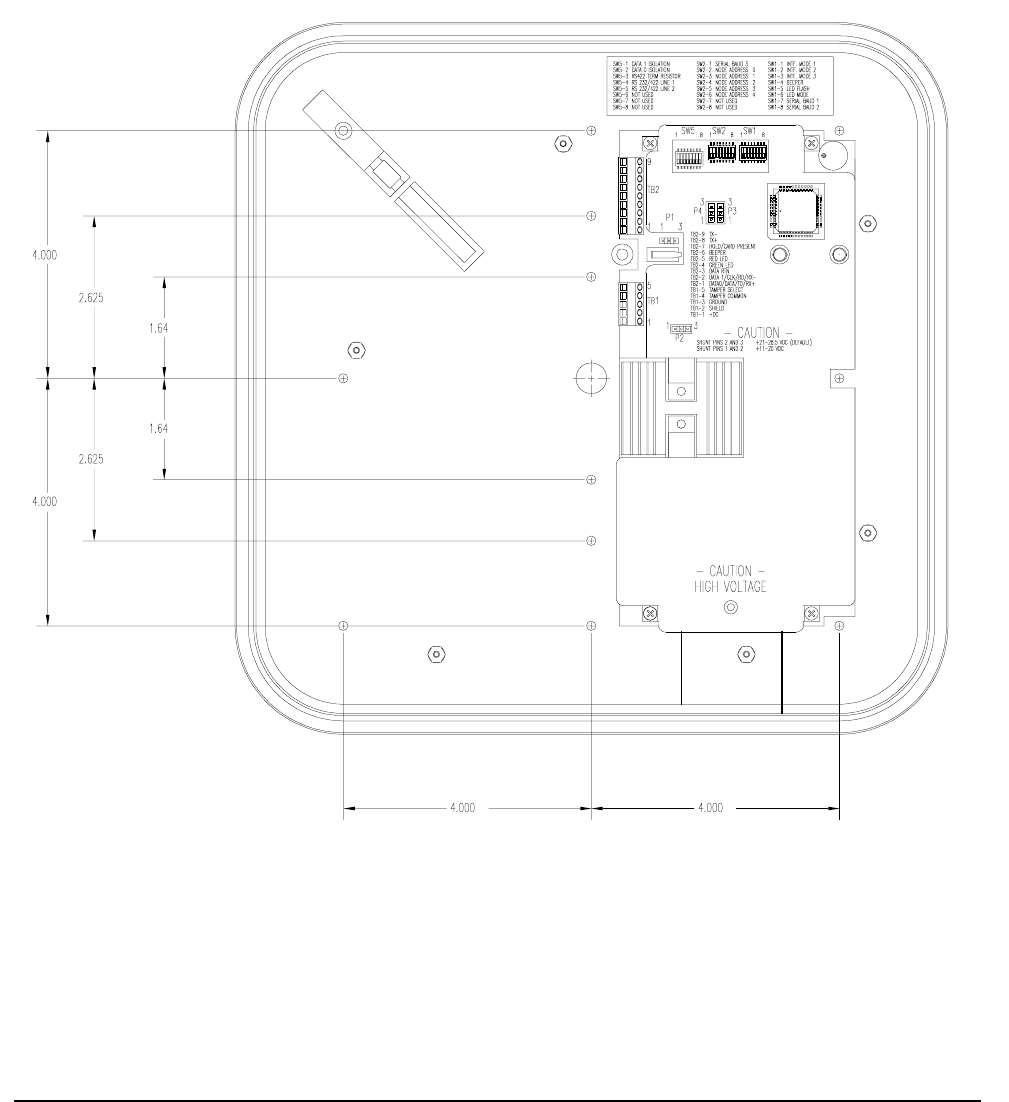
Mount the base of the MaxiProx that holds the electronics to the surface using the holes located on the base
of the Reader. There are 12 recessed holes for mounting. The holes are not through holes and require drilling
before mounting. Chose the appropriate holes to be used and drill with a 5/32 (.156) inch bit. Use #6 screws
only. (See figure 2).

__________________________________________________________________________________________________________
HID Corporation, 9292 Jeronimo Road, Irvine, CA 92618-1905, USA •Tel: (949) 598-1600, (800) 237-7769, Fax: (949) 598-1690
http://www.hidcorp.com MaxiProx Reader Installation Manual 5375-900 REV 06 Page 6
2.11
2.11 2.11
2.11 Power Supply
Power SupplyPower Supply
Power Supply
The MaxiProx Reader can be operated over the full range of 11-28.5VDC. Current requirements are 200
mA average and 700 mA peak at 12 VDC input. At 24 VDC (21 to 28.5 VDC) input the average current is
260 mA and peak is 1.2 A. A linear regulated supply rated at 2.0 A is recommended. Noise from devices
such as switching power supplies, computer monitors, and arc welders can reduce the read range or make the
unit inoperable. Keep these devices at least 10 ft away from the Reader. With the MaxiProx and power
supply wired together, apply power to the Reader.
CAUTION!
The shunt jumper P2 is not installed as the factory default for +24VDC operation. If the jumper is in the +12
VDC position and +21 to +28.5 VDC is applied, circuit damage can result.
2.12
2.12 2.12
2.12 Autotune Operation
Autotune OperationAutotune Operation
Autotune Operation
The MaxiProx is tuned correctly when the autotune LED is green. If the LED is red, use a spacer to
position the Reader at minimum of 4 inches away from metal in the mounting surface.
2.13
2.13 2.13
2.13 Reader Testing
Reader Testing Reader Testing
Reader Testing
Apply Power to the Reader and the LED will display a sequence of flashes and beeps, indicating the LED
control mode. Two flashes of green and two beeps followed by a short delay, then one additional flash
(beep), is the correct sequence for "Green Flash/Beep on valid read” (SW1-5 off). Three initial green flashes
and beeps followed by a pause and then one additional beep indicate no Green Flash/Beep on valid read
(SW1-5 on).
2.14
2.14 2.14
2.14 Power-Up Tune
Power-Up TunePower-Up Tune
Power-Up Tune
Following this initial power up sequence the Reader will perform power-up Autotune. It will beep and turn
the access LED amber for ~1 second to indicate that a power-up tune test is about to begin. It will then
attempt to tune. If it successfully tunes, it will give two quick beeps and a green on the access and tune
LED's to indicate the Reader is tuned. If unsuccessful, the unit will give a single 1.5-second beep with a red
on the access and tune LED’s. If Autotune is not successful, the installer should check for large areas of
metal less than 4 inches from the back of the unit.
2.15
2.15 2.15
2.15 Periodic Autotune
Periodic AutotunePeriodic Autotune
Periodic Autotune
Periodic Autotune retunes every 1 minute.
2.16
2.16 2.16
2.16 Supervisor Mode
Supervisor ModeSupervisor Mode
Supervisor Mode
During idle periods in normal operation, a periodic supervisor 1 byte transmission is sent to the host
controller over the Wiegand interface every 1 minute. Supervisor Mode is only available in Wiegand
Interface Mode.
2.17
2.17 2.17
2.17 Install Cover
Install CoverInstall Cover
Install Cover
Replace the top cover and top cover screw. Make sure that the autotune indicator LED remains in a steady
green state. If the LED is red, remove the cover and re-mount the unit using a non-metallic spacer to position
it further away from the mounting surface. Reinstall the cover, verify autotune, and install the front label over
the top cover screw and the autotune indicator lens.
__________________________________________________________________________________________________________
HID Corporation, 9292 Jeronimo Road, Irvine, CA 92618-1905, USA •Tel: (949) 598-1600, (800) 237-7769, Fax: (949) 598-1690
http://www.hidcorp.com MaxiProx Reader Installation Manual 5375-900 REV 06 Page 7
Figure 1: MaxiProx Front View
__________________________________________________________________________________________________________
HID Corporation, 9292 Jeronimo Road, Irvine, CA 92618-1905, USA •Tel: (949) 598-1600, (800) 237-7769, Fax: (949) 598-1690
http://www.hidcorp.com MaxiProx Reader Installation Manual 5375-900 REV 06 Page 8
Figure 2: MaxiProx interior view showing mounting hole locations

__________________________________________________________________________________________________________
HID Corporation, 9292 Jeronimo Road, Irvine, CA 92618-1905, USA •Tel: (949) 598-1600, (800) 237-7769, Fax: (949) 598-1690
http://www.hidcorp.com MaxiProx Reader Installation Manual 5375-900 REV 06 Page 9
Chapter 3 Installation Notes and Guidelines
3.1
3.1 3.1
3.1 Power Supply
Power SupplyPower Supply
Power Supply
The recommended power supply is 12 or 24VDC, nominal, 2.0A current rating, linear regulated. The
MaxiProx cycles through varying power stages and has a peak current demand of approximately 1.2A when
in long range read mode. Average current consumption is about 260mA. Failure to provide an adequate
current capacity power supply will result in reduced read range.
CAUTION!
The shunt jumper P2 is not installed as the factory default for +24VDC operation. If the jumper is in the +12
VDC position and +21 to +28.5 VDC is applied, circuit damage can result.
The use of a Power Switching Supply is not recommended for two reasons:
(1) This type of supply does not provide adequate response to rapid transient current loads and also
generates radio frequency (RF) interference in the same band that the Reader receives data and;
(2) The power supply may generate noise that is large enough to be transmitted or conducted to the
MaxiProx that interferes with the reception of a card signal. Some switching power supplies are not able
to provide adequate regulation to the MaxiProx Reader.
3.2
3.2 3.2
3.2 Installation near Metal
Installation near MetalInstallation near Metal
Installation near Metal
Read range will be reduced if located on metal surfaces or in the vicinity of metal objects. The amount of
reduction will be a factor of the amount of metal and the distance the Reader is from the metal. Metal near
the Reader absorbs energy from the Reader excite field and affects the signal being received from the card by
re-directing excite field transmissions into the receiver circuitry. Moving the Reader away from the metal
objects reduces energy loss.
Try to limit the amount of metallic materials installed near the MaxiProx. Use a plastic electrical box if
possible. Avoid installing conduit and other metal hardware within 2-inches of the back of the Reader or
closer than 4-inches from large metal surfaces. The typical read distance specification (24-29 inches at 21-
28.5 VDC or 21-26 inches at 12 VDC) refers to operation without metal in the vicinity of the Reader. The
read distance will be reduced if metal is installed nearby.
The MaxiProx generates a magnetic field on all sides of the Reader. Any metal that conducts electricity,
especially metal that contains iron, steel or copper will interfere with the field and reduce the effective read
range (this will happen even if the metal is behind the Reader). It helps to put a non-metallic spacer between
the Reader and the metal object.
3.3
3.3 3.3
3.3 Radio Frequency Interference
Radio Frequency InterferenceRadio Frequency Interference
Radio Frequency Interference
Motors and electronic devices generate RF noise that may interfere with the reception of the signal from a
transponder. The affect of RF noise is typically a reduction of read range. The MaxiProx is susceptible to RF
interference, as are all devices that receive RF signals. The read range is affected by the amount of
interference (noise) in the area. Common sources of RF interference are power supplies, electrical and
electronic equipment, some types of lighting, computers and monitors, motors and generators. Moving the
Reader to a location known to be free of interference and testing read range there will help to isolate RF
interference as a factor in low read range situations.

__________________________________________________________________________________________________________
HID Corporation, 9292 Jeronimo Road, Irvine, CA 92618-1905, USA •Tel: (949) 598-1600, (800) 237-7769, Fax: (949) 598-1690
http://www.hidcorp.com MaxiProx Reader Installation Manual 5375-900 REV 06 Page 10
The MaxiProx should not be mounted within six feet of any monitors (VDTs or CRTs) because the scan
frequencies of most monitors include frequencies that may interfere with the signal received from the access
control cards.
3.4
3.4 3.4
3.4 Transponder Types
Transponder TypesTransponder Types
Transponder Types
The type of transponder used affects the read range of the MaxiProx. The various styles of HID cards and
transponders use different types of antennas. The antenna type will determine the read range for that type of
transponder. The Vehicle ID tag provides the longest read range at 32-36 inches; the ProxCard II is 24-29
inches. The IsoProx/DuoProx is 17-20 inches. The ProxKey reads at a distance of 15-17 inches.
Note
The above are recommended installation procedures. All local, state and national electrical codes have
precedence.

__________________________________________________________________________________________________________
HID Corporation, 9292 Jeronimo Road, Irvine, CA 92618-1905, USA •Tel: (949) 598-1600, (800) 237-7769, Fax: (949) 598-1690
http://www.hidcorp.com MaxiProx Reader Installation Manual 5375-900 REV 06 Page 11
Chapter 4 Application Notes
4.1
4.1 4.1
4.1 Wiegand Interface Description
Wiegand Interface DescriptionWiegand Interface Description
Wiegand Interface Description
4.1.1 Wiegand Message Format
In the Wiegand format, the ID card is programmed with a specific bit pattern and the Reader acquires the
data, checks the customer code and generally sends out the same bit pattern as previously programmed on
the card. Consult factory for variations to this method. A 26 bit Wiegand format will be used in the examples
below.
The 26 bits of transmission from the Reader to the panel consists of two parity bits and 24 code bits. The
bits are transmitted in the order described. The first bit transmitted is the first parity bit, P1; it is even parity
calculated over the first 12 code bits. The last bit transmitted is the second parity bit, P2; it is odd parity
calculated over the last 12 code bits:
Code Format
11111111112222222
12345678901234567890123456
P1CCCCCCCCCCCCCCCCCCCCCCCCP2
Parity Format
11111111112222222
12345678901234567890123456
P1EEEEEEEEEEEE
OOOOOOOOOOOOP2
P1: First, or even parity bit
C: Code bits
P2: Second, or odd parity bit
E: Bits for calculation of even parity
O: Bits for calculation of odd parity
Data format within the 24 code bits which includes the portioning of the bit, the designation of the Most
Significant Bit (MSB) or the Least Significant Bit (LSB) shall be subject to definition by the panel and
Reader manufacturers and may remain proprietary.
4.1.2 Output Specification
The specifications of voltage, current, power and timing are from the perspective of the Reader. A common
signal ground is defined as a voltage reference that is common to both the Reader and the control panel. The
voltages for the data outputs are referenced from the power supply ground located at the Reader. The
voltage measured for the power to the Reader is referenced from the power supply-return connection location
at the Reader, not at the source of the power.
__________________________________________________________________________________________________________
HID Corporation, 9292 Jeronimo Road, Irvine, CA 92618-1905, USA •Tel: (949) 598-1600, (800) 237-7769, Fax: (949) 598-1690
http://www.hidcorp.com MaxiProx Reader Installation Manual 5375-900 REV 06 Page 12
The voltage, current, and timing of the data pulses are measured at the Reader in reference to the power
supply/signal ground at the Reader. The voltage, current and timing of a signal driving an auxiliary input
device on a Reader is measured at the control panel that is controlling the input device (with reference to the
signal ground at the panel).
4.1.3 Signal Levels
The Data One, Data Zero, and LED Control conductors connect signals between the Reader and the panel.
The logic levels are defined as follows:
Table 9: Logic Levels
Voltage Data Outputs (Data0 and Data1) Control Inputs (LED’s, Hold, Beeper)
Levels Minimum Maximum Minimum Maximum
Voh 3.5V 5.5V 3.5V 5.5V
Vol 0.0V 0.5V 0.0V 0.5V
Ioh 0.0mA 5.0mA -1.0mA 0.0mA
Iol -25.0mA 0.0mA 0.0mA 25.0mA
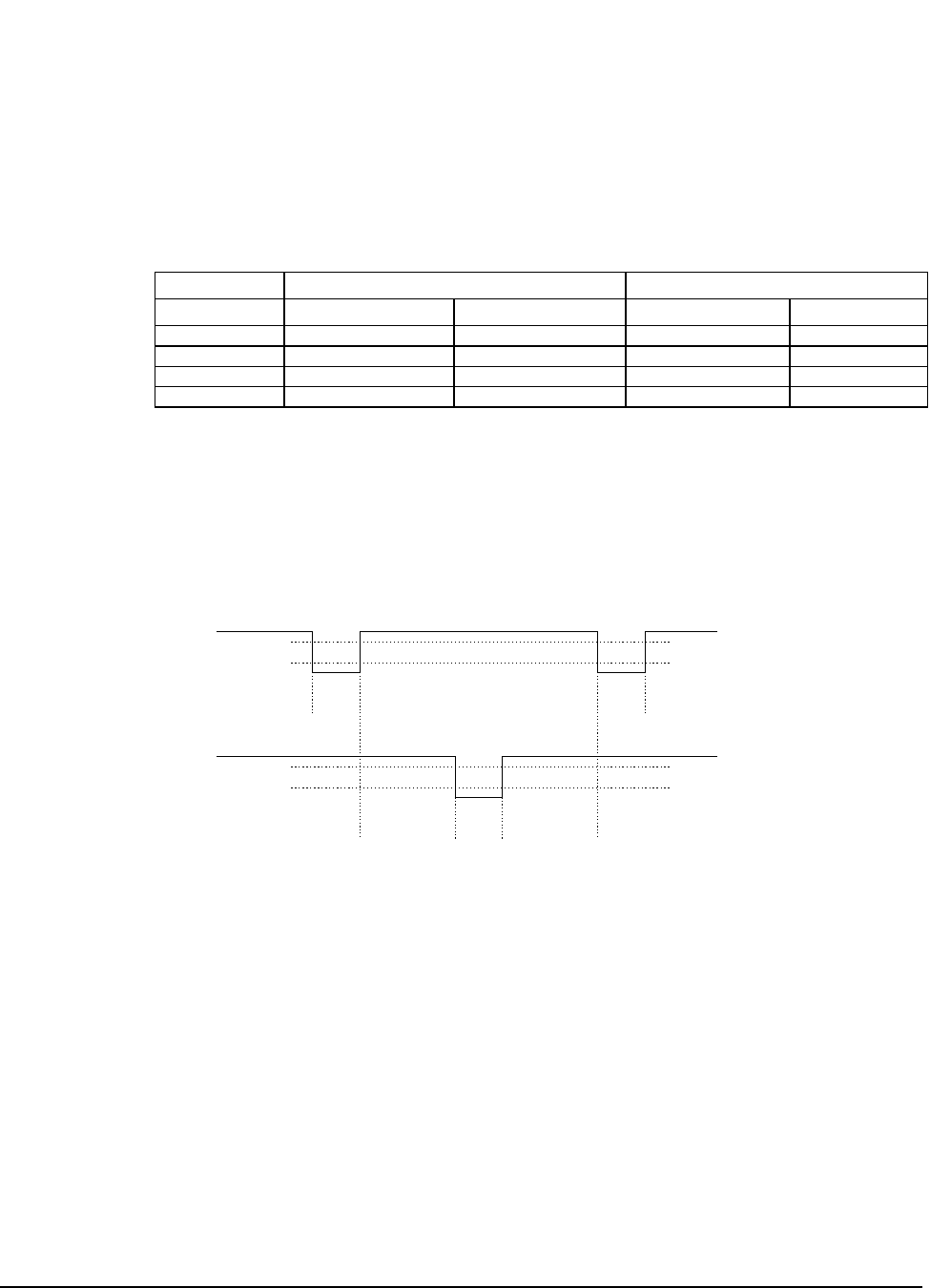
4.1.4 Data Pulses
The Data One and Data Zero signals are normally held at a logic high level until the Reader is ready to send
a data stream. The Reader places asynchronous low pulses on the appropriate data lines to transmit the data
stream to the panel. The following timing parameters shall be observed:
Figure 3: Data Pulses - Timing Parameters
Tpw Pulse Width Time - 30uS (minimum) to 50uS (maximum)
Tpi Pulse Interval Time - 1.8mS (minimum) to 2.2mS (maximum)
4.1.5 Example Output
The following is an example of an ID card with the number of “816” decimal, which will be output by the
MaxiProx Reader, the number “02004CA0661” hex.
Data One
Data Zero
Tpw Tpw
Tpw TpiTpi
Voh
Voh
Vol
Vol

__________________________________________________________________________________________________________
HID Corporation, 9292 Jeronimo Road, Irvine, CA 92618-1905, USA •Tel: (949) 598-1600, (800) 237-7769, Fax: (949) 598-1690
http://www.hidcorp.com MaxiProx Reader Installation Manual 5375-900 REV 06 Page 13
Note
The customer code is never transmitted or displayed.
4.2
4.2 4.2
4.2 Clock and Data Interface Description
Clock and Data Interface DescriptionClock and Data Interface Description
Clock and Data Interface Description
4.2.1 Clock and Data Message Format
The Clock and Data interface consists of three signals, Card Present, Data and Strobe/Clock. The interface is
a serial data stream, which is controlled with a clock/strobe that indicates when data is valid. All signals are
quiescent high. Card Present goes low when data is about to be sent and remains low until the whole data
stream is completed. Data is the signal that determines the “ones” and “zeros”. Strobe/Clock is the signal
that indicates when data is valid for each cycle.
The Track 2 message format is a stream of binary bits that are grouped into HEX characters. The message
starts with leading zeros, followed by a start sentinel, data, end sentinel, LRC and trailing zeros. Each HEX
character has error correction in the form of a parity bit. Each character consists of five bits. The maximum
number of characters for a magnetic strip card encoded on Track 2 are 40, this product will output less than
40 characters. The data consists only of BCD digits, the remaining HEX digits, A to F, are used for the start
and end sentinel, data separators and control. Only hex B and F are used, A, C D and E are not used. The
message will consist of a minimum of 210 bits.
The bits of a character are in the order 1248P, where parity is odd over the four bits. The LRC is the Xoring
of the message, starting with the start sentinel and ending with the end sentinel. The LRC does not include
the parity bits of the characters in the Xoring. LRC does include its own odd parity bit that covers the four
bits that are the result of the Xoring.
<leading zeros><Start Sentinel><data><data>........<data><End sentinel><LRC><trailing zero>
Customer code 0,1, 63, 72 and 73 (existing customer codes) cards will be read and output in the Track 2
format. The data on these cards will be packed into the Track 2 format in segments of three bits, so the
character does not exceed a BCD seven.
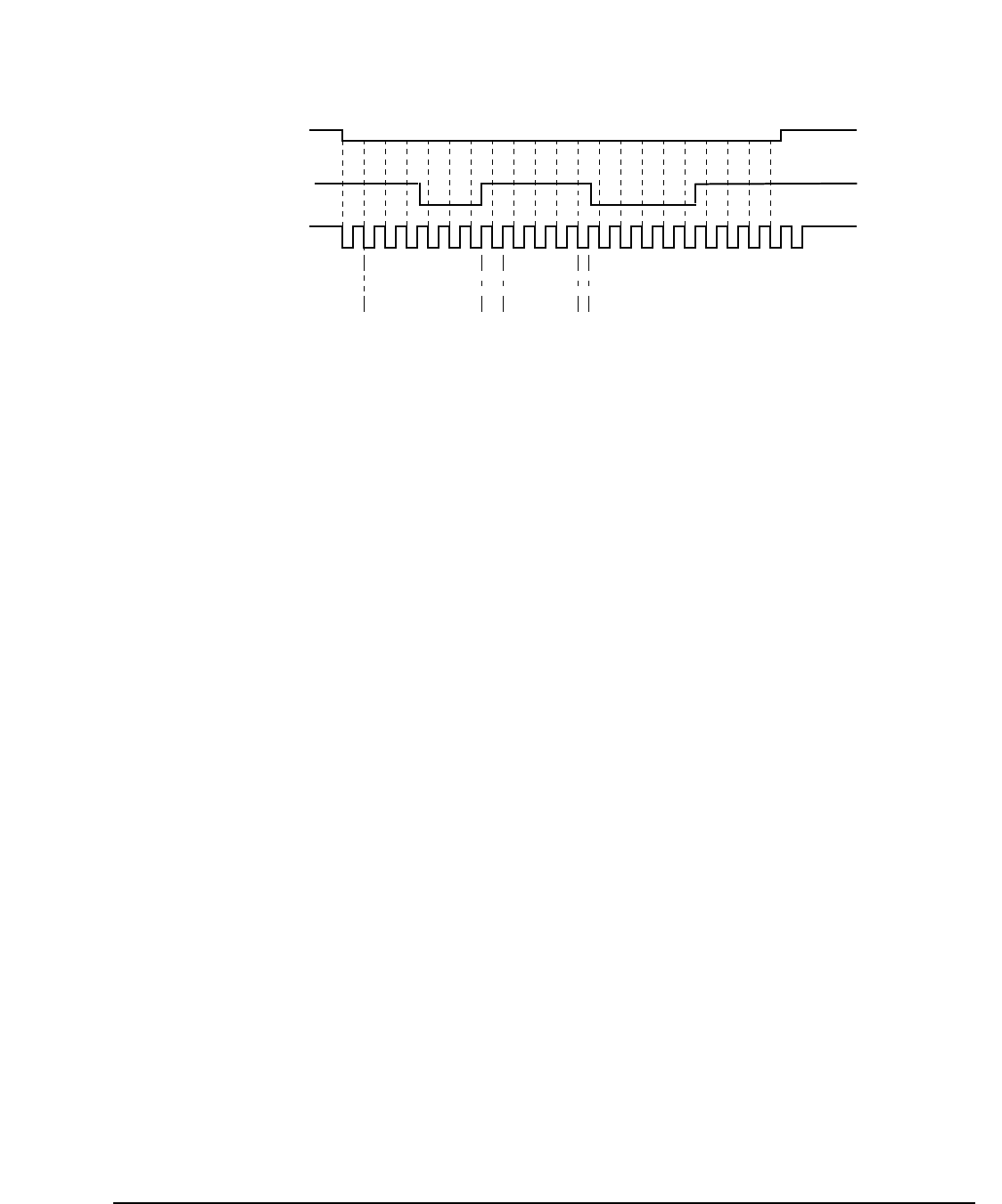
4.2.2 Data Timing
The outputs, Card Present, Data and Strobe are low going signals and the following timing chart describes
the timing.
sentinel parity parity
customer code 10 zeros bit even facility code card number odd
[0 0 0 0 0 0 1] [0 0 0 0 0 0 0 0 0 0] [1] [0] [0 1 1 0 0 1 0 1] [0 0 0 0 0 0 1 1 0 0 1 1 0 0 0 0] [1]
| 0 | 2 | 0 | 0 | 4 | C | A | 0 | 6 | 6 | 1 |
Wiegand Output | 0 | C | A | 0 | 6 | 6 | 1 |
Hex code numbers [ 6 | 5 ][ 0 | 3 | 3 | 0 ]
Decimal conversion [ 101 ][ 0816 ]
__________________________________________________________________________________________________________
HID Corporation, 9292 Jeronimo Road, Irvine, CA 92618-1905, USA •Tel: (949) 598-1600, (800) 237-7769, Fax: (949) 598-1690
http://www.hidcorp.com MaxiProx Reader Installation Manual 5375-900 REV 06 Page 14
Figure 4: Data Timing - Timing Chart
1
000
111
00000
1111
0000
bit time strobe width
card present
data
clock/
strobe
1st valid bit
Note: the first 25 bits and trailin
g
bits are zeros, not shown above.
bit time = 1.5ms (default)
strobe width = bit time/3 (33% of bit time), default = 500us
Clock/Strobe is valid 1.5ms (one clock cycle, min) after card present is asserted
Data is valid 10us (min) before the negative edge of clock/strobe
Card Present returns to the high level 50 ms (max) after the last clock/strobe.
The above timing is representative of a magnetic stripe card traveling at 8.9 inches per second. The timing is
to be adjustable for cards traveling at 4 inches per second to 20 inches per second. This relates to bit times of
3.3 ms and 666us, respectively. There are 75 bits per inch on Track 2.
4.2.3 Output signal Levels
Inputs: low threshold = 0.8 volts high threshold = 3.5 volts
4.2.4 Bit structure
The Reader will read an 1849 or compatible chip that is encoded with 44 bits of data. The data will be
programmed in accordance with ProxGuard formatting. The data will be packed into the ABA/ISO Track 2
message format in accordance with the following rules based on customer code:
Case 1:
Customer Code = 0, 1, 63, 72, 73 or other, will have the data output as follows.
The output is in the Track 2 character format but the bits are packed in sets of three bits (octal):
ccc CCCC a bcd efg hij klm nop qrs tuv wxy zAB CDE FGH IJK
Where cccCCCC is the customer code, abc...IJK is the programmed data on the card.

__________________________________________________________________________________________________________
HID Corporation, 9292 Jeronimo Road, Irvine, CA 92618-1905, USA •Tel: (949) 598-1600, (800) 237-7769, Fax: (949) 598-1690
http://www.hidcorp.com MaxiProx Reader Installation Manual 5375-900 REV 06 Page 15
1248p 1248p 1248p1248p 1248p1248p 1248p1248p1248p1248p 1248p1248p1248p 1248p 1248p 1248p 1248p1248p1248p
<B> c000p Ccc0p CCC0p a000p dcb0p gfe0p jih0p mlk0p pon0p srq0p vut0p yxw0p BAz0p EDC0p HGF0p KJI0p <F><LRC>
Case 2:
Customer Code = 74 are structured as follows:
421 8421 8421 8421 8421 8421 8421 8421 8421 8421 8421
CCC CCCC 1 aaaa bbbb cccc dddd eeee ffff gggg hhhh iiii
CCC CCCC - Customer code
1 - fixed bit “1”
aaaa - Most significant nibble of message
bbbb - Second MSN
cccc - next nibble
hhhh - least significant nibble of message
iiii - LRC of nibbles aaaa to hhhh, start (B) and end sentinel (F) (xor of the nibbles or the even parity of the respective
column)
The output from the Reader will look like the following:
1248p 1248p 1248p 1248p 1248p 1248p 1248p 1248p 1248p 1248p 1248p
<B> <aaaap> <bbbbp> <ccccp> <ddddp> <eeeep> <ffffp> <ggggp> <hhhhp> <F> <iiiip>
start data a data b data c data d data e data f data g data h end LRC
The message structure follows the ISO/ABA Track 2 standard. The first character is a start sentinel: B (hex),
which is followed by data. After the data there is an end sentinel: F (hex), followed by an LRC. The LRC is
the xoring of the message in accordance to the bit position. Each character has an odd parity bit that covers
bit 1 to bit 4 of the nibble.
A typical message:
B 1 2 3 F LRC the bits broken down:
1248p 1248p 1248p 1248p 1248p 1248p
11010 10000 01000 11001 11111 00101
B 1 2 3 F 4
start < data > end LRC
4.2.5 Bit Stream

__________________________________________________________________________________________________________
HID Corporation, 9292 Jeronimo Road, Irvine, CA 92618-1905, USA •Tel: (949) 598-1600, (800) 237-7769, Fax: (949) 598-1690
http://www.hidcorp.com MaxiProx Reader Installation Manual 5375-900 REV 06 Page 16
The bit stream will consist of 25 leading zeros, the message and fill with zeros until the end of the message.
The message will consist of a minimum of 210 bits.
Example
00000000000000000000000000 11010 10000 01000 11001 11111 00100 00000000000000...000000
B 1 2 3 F LRC
4.2.6 Output Specification
Vol = 0.8 V
Voh = 3.5 V
sink = 25 ma
source = 5 ma
4.3
4.3 4.3
4.3 RS232 and RS422 Card Message Specification (Send Mode Only)
RS232 and RS422 Card Message Specification (Send Mode Only)RS232 and RS422 Card Message Specification (Send Mode Only)
RS232 and RS422 Card Message Specification (Send Mode Only)
When Access Cards (transponders) are presented to the MaxiProx Reader, the Reader sends a message. The
message is in the following format:
CCDDDDDDDDDDXX<CR><LF>
^ First character sent
All characters C, D and X are ASCII encoded, hexadecimal digits. (i.e., the hex value 7 is sent as an ASCII
character 7 or the hex value E is sent as an ASCII character E).
The CC field is reserved for use by HID Corporation. The valid values are 00 through 7F.
The DDDDDDDDDD field is the transponders (Access Card) data. The valid values are 0000000000 through
1FFFFFFFFF (ASCII).
The XX field is a computed checksum. The checksum is calculated by first grouping the message data into the
pairs CC DD DD DD DD DD. Each pair of characters represents one byte of data. Then each pair of characters is
converted from ASCII to their respective hex values. At this point, the 6 bytes are added together. The
checksum is equal to the least significant 8 bits of the result.
<CR> is the ASCII code for a carriage return. (0D hex)
<LF> is the ASCII code for a line feed. (0A hex)
For example, if the MaxiProx reads a transponder (Access Card) that contains the value CC=00 and
DDDDDDDDDD=01234ABCDE, the Reader will report the ASCII message 0001234ABCDE08<CR><LF>.
Note that each of the characters is ASCII encoded. The actual bytes (hex value) that are sent to the host are:
<30><30><30><31><32><33><34><41><42><43><44><45><30><38><0D><0A>
The checksum was computed by adding 00 + 01 + 23 + 4A + BC + DE = 208 hex. The checksum is the least
significant 8 bits of this result or 08 hex. The communications settings are 9600-75Hz BAUD, 8 bits, 1 stop
bit, no parity.