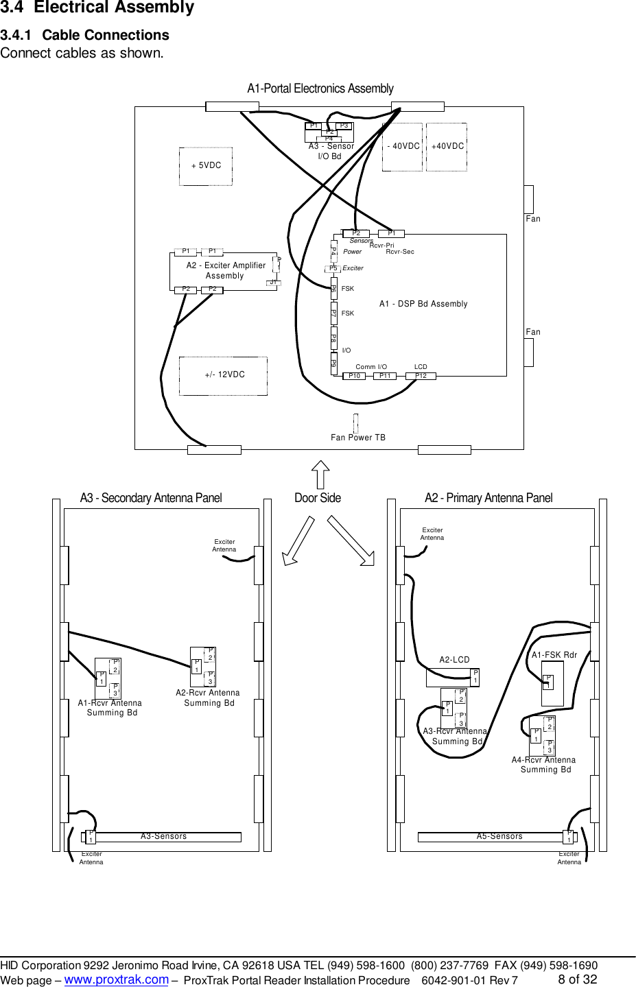
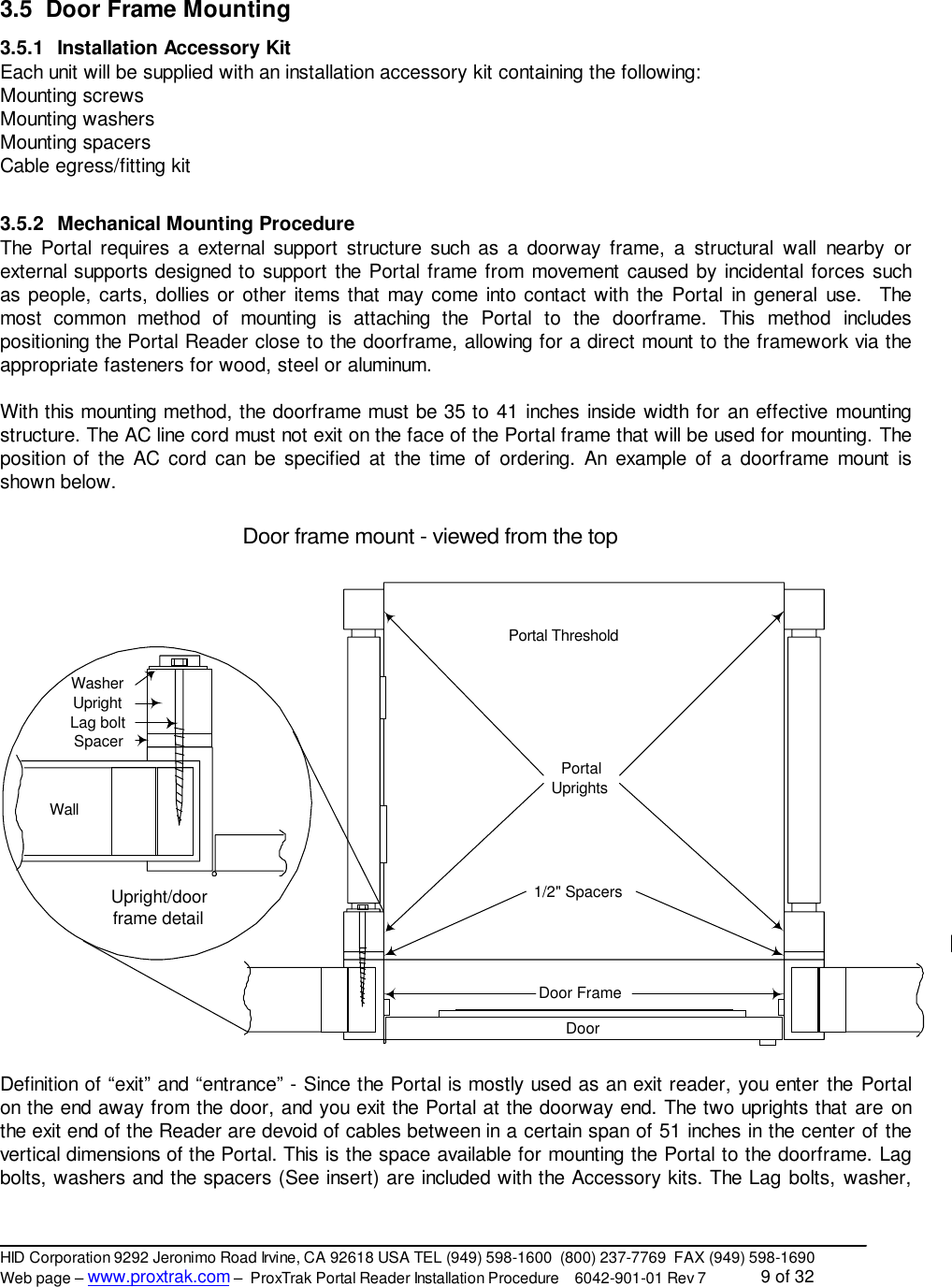
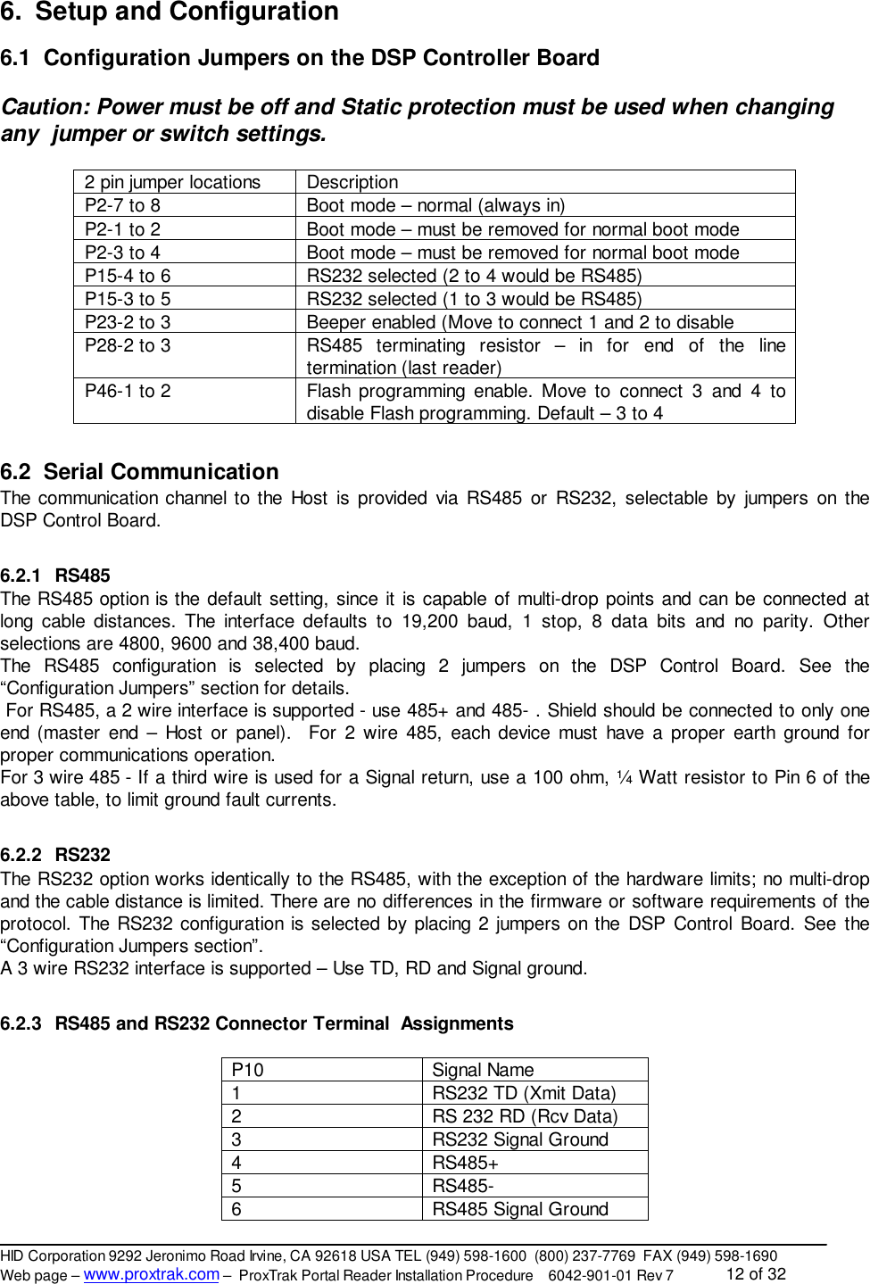
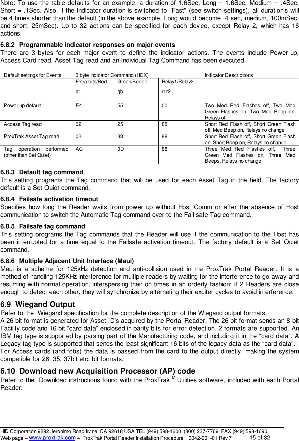
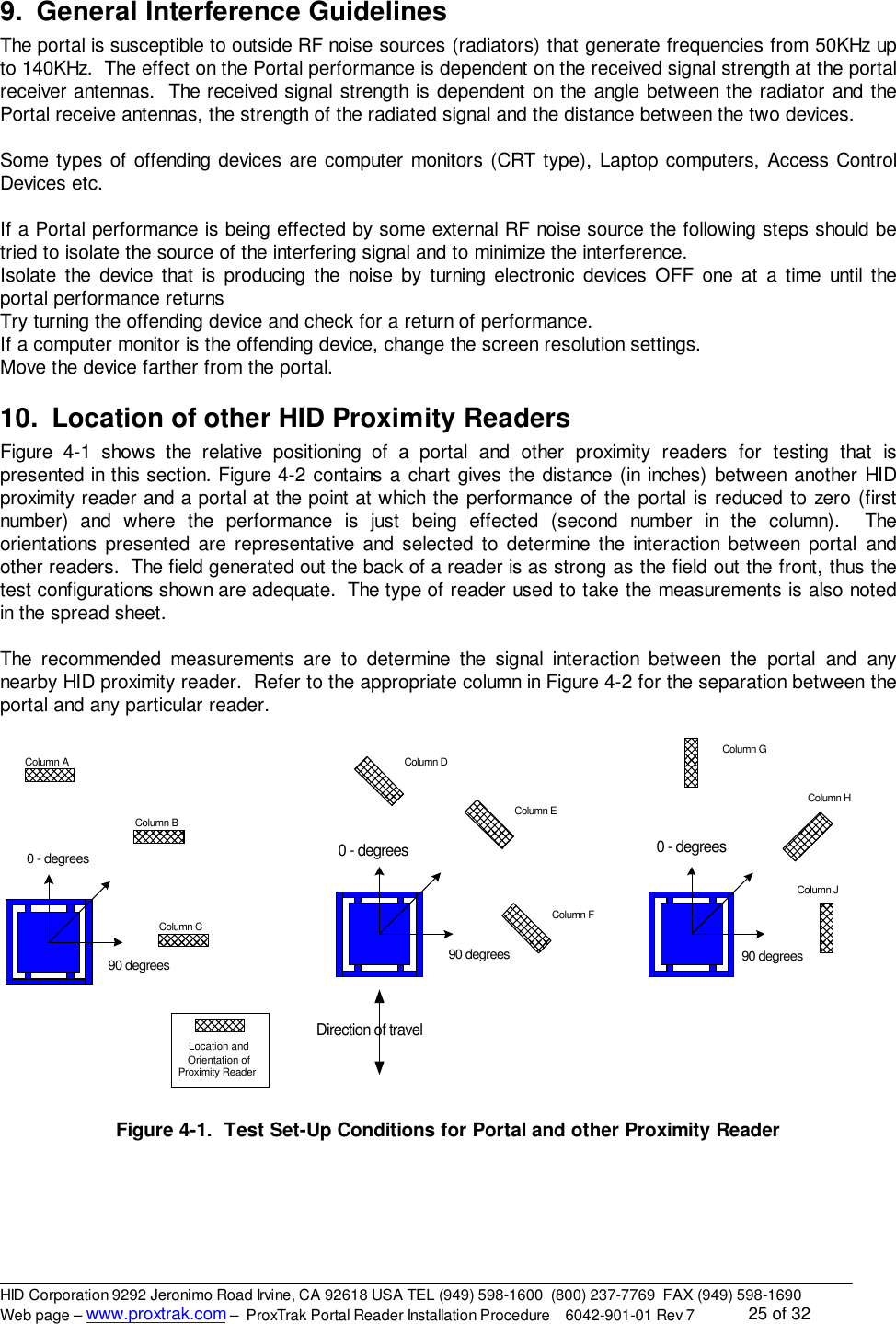
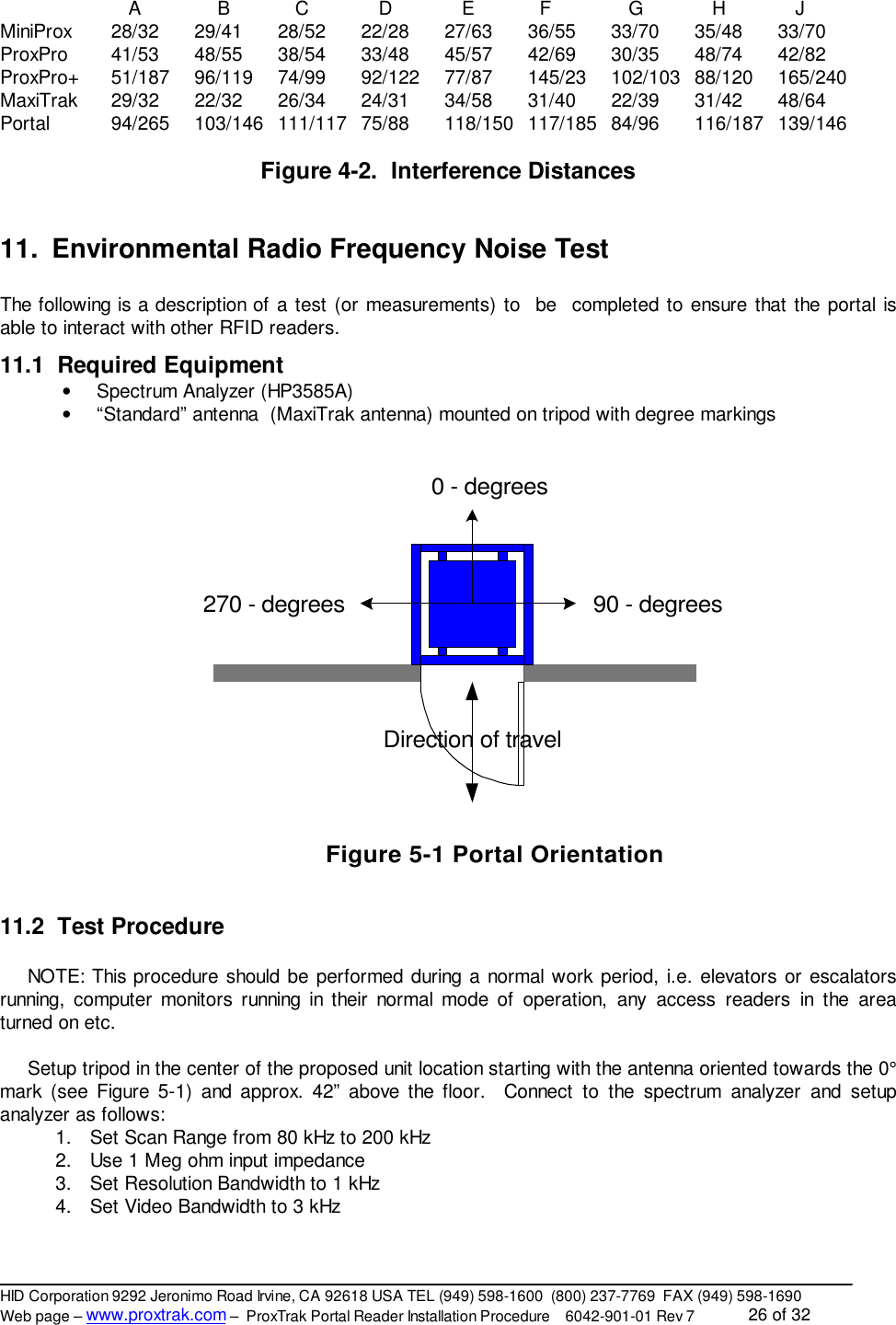
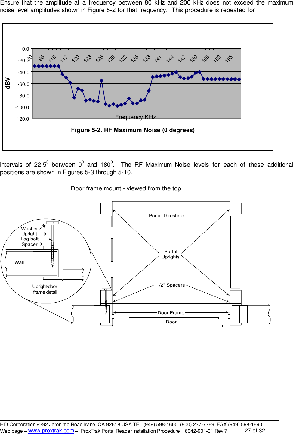
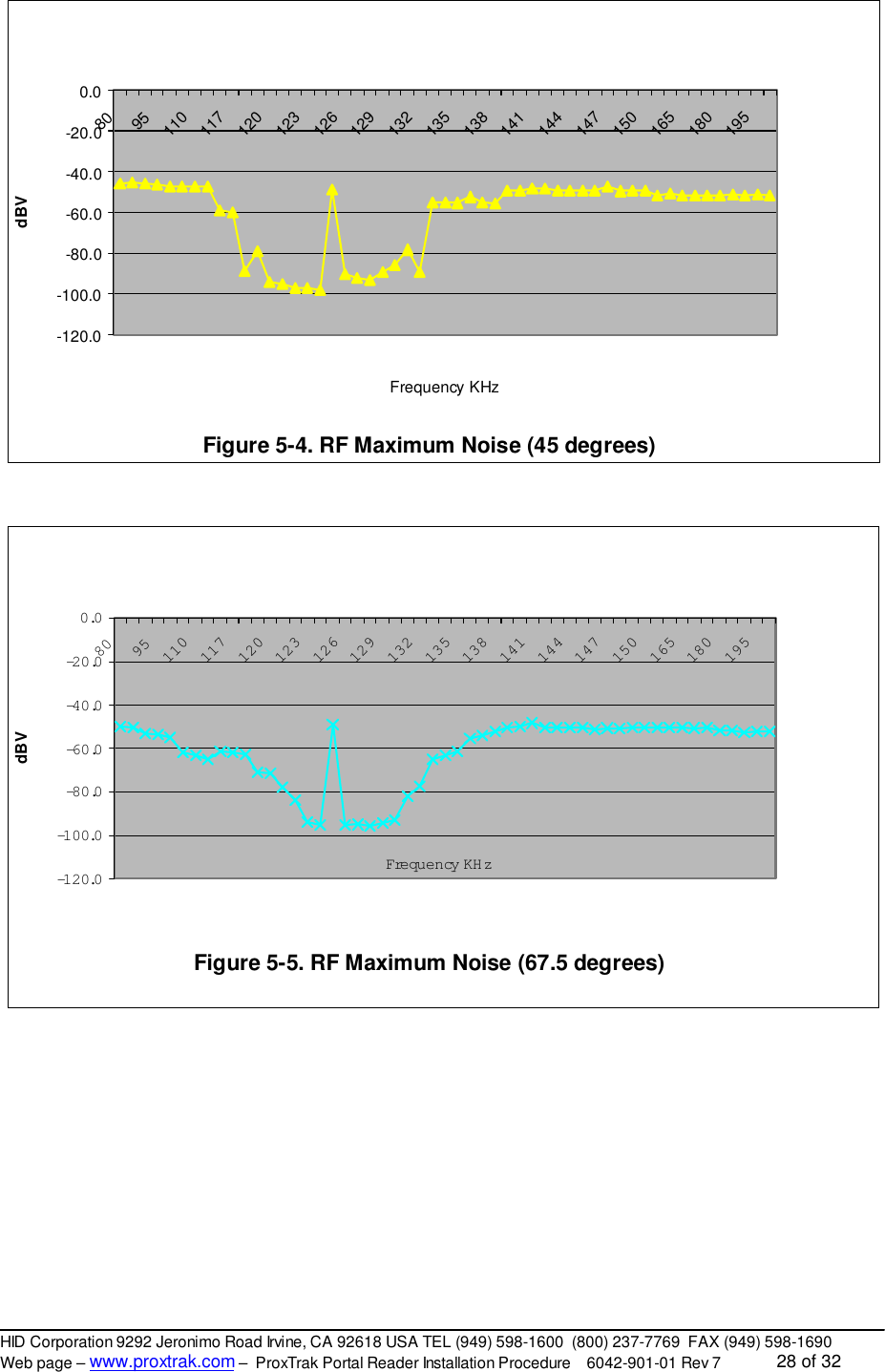
HID Global 6042AA AMP1000 Portal Reader 6042 (6042-300) User Manual Portal Installation Manual Rev 7

HID Global Corporation AMP1000 Portal Reader 6042 (6042-300) Users Manual Portal Installation Manual Rev 7

Users Manual Portal Installation Manual Rev 7

.REV DESCRIPTION DATE APPROVED7NOTE:  Cover sheet is for Revision Control only, and is not to be sent with document.REVSHEET 35 36 37 38 39 40 41 42 43 44 45 46 47 48 49 50 51 52REVSHEET 17 18 19 20 21 22 23 24 25 26 27 28 29 30 31 32 33 34REV STATUSOF SHEETS 1 2 3 4 5 6 7 8 9 101112131415 16TOLERANCES APPROVALS DATE HID CORPORATION.XX = +/- .03” DWN   G. FOSSEN 120799 IRVINE, CALIFORNIA.XXX = +/- .010” CHK Installation ProcedureANGLES = +/- 1°APVD  ProxTrak Portal ReaderMATERIAL N/A APVDFINISH N/A P/N               6042-901-01 REV 7SCALE N/A SIZE          A SHEET 0 OF 19
_________________________________________________________________________________________HID Corporation 9292 Jeronimo Road Irvine, CA 92618 USA TEL (949) 598-1600  (800) 237-7769  FAX (949) 598-1690Web page – www.proxtrak.com –  ProxTrak Portal Reader Installation Procedure    6042-901-01 Rev 7              1 of 32ProxTrakTM Portal Reader Installation Procedure6042-901-01 Rev 7
_________________________________________________________________________________________HID Corporation 9292 Jeronimo Road Irvine, CA 92618 USA TEL (949) 598-1600  (800) 237-7769  FAX (949) 598-1690Web page – www.proxtrak.com –  ProxTrak Portal Reader Installation Procedure    6042-901-01 Rev 7              2 of 32Table of Contents1. AMP100 ProxTrakTM Portal Reader Installation Manual.............................................................. 41.1 Scope .................................................................................................................................. 41.2 Functional Summary.............................................................................................................. 41.3 Reference Documents........................................................................................................... 42. Site Requirements ..................................................................................................................... 42.1 Physical Requirements .......................................................................................................... 42.1.1 Floor ............................................................................................................................. 42.1.2 Mounting........................................................................................................................ 52.2 Power Requirements............................................................................................................. 52.3 Host or Panel Communication Requirements ........................................................................... 52.4 Environmental Limits.............................................................................................................. 52.5 Materials.............................................................................................................................. 53. Physical Installation................................................................................................................... 53.1 Unpacking............................................................................................................................. 53.2 AMP100 Portal Reader Dimensions with mounting points ......................................................... 63.3 Mechanical Assembly Procedure............................................................................................ 73.4 Electrical Assembly............................................................................................................... 83.4.1 Cable Connections..........................................................................................................83.5 Door Frame Mounting............................................................................................................ 93.5.1 Installation Accessory Kit ................................................................................................ 93.5.2 Mechanical Mounting Procedure ...................................................................................... 94. System Checkout and Test.......................................................................................................104.1 Power Supply Check...........................................................................................................104.2 Exciter Tuning..................................................................................................................... 104.3 Receiver Null....................................................................................................................... 104.4 System Performance...........................................................................................................105. Installation into an Asset Management System.........................................................................105.1 Input and Output Signal Information...................................................................................... 105.1.1 Serial cable for Host communications..............................................................................105.1.1.1 Maximum Cable Lengths.............................................................................................105.1.1.2 Communications Pin Assignments................................................................................115.1.2 Relays..........................................................................................................................115.1.3 Wiegand Interface .........................................................................................................115.1.4 Second FSK Reader......................................................................................................116. Setup and Configuration...........................................................................................................126.1 Configuration Jumpers on the DSP Controller Board .............................................................. 126.2 Serial Communication.......................................................................................................... 126.2.1 RS485..........................................................................................................................126.2.2 RS232..........................................................................................................................126.2.3 RS485 and RS232 Connector Terminal  Assignments.......................................................126.2.4 Baud Rate and Node Address ........................................................................................136.3 Polled mode ....................................................................................................................... 136.4 Simplex mode..................................................................................................................... 136.5 LCD interface ..................................................................................................................... 136.6 Tag Command options......................................................................................................... 136.6.1 Default Tag commands..................................................................................................136.6.2 Failsafe Tag commands.................................................................................................136.6.3 Host controlled Tag commands.......................................................................................136.6.3.1 Individual ProxTrakTM Commands ................................................................................146.6.3.2 Global ProxTrakTM Commands ....................................................................................14
_________________________________________________________________________________________HID Corporation 9292 Jeronimo Road Irvine, CA 92618 USA TEL (949) 598-1600  (800) 237-7769  FAX (949) 598-1690Web page – www.proxtrak.com –  ProxTrak Portal Reader Installation Procedure    6042-901-01 Rev 7              3 of 326.7 Indicators ........................................................................................................................... 146.7.1 Red/Green LED and Beeper in the Access control Reader ...............................................146.7.2 Red/Green LED and Beeper located on the DSP controller electronics..............................146.7.3 Relay 1 and Relay 2 ......................................................................................................146.8 EEPROM Configuration information...................................................................................... 146.8.1 Indicators (LED's, Beeper, Relays) duration's..................................................................146.8.2 Programmable indicator responses on major events.........................................................156.8.3 Default tag command.....................................................................................................156.8.4 Failsafe activation timeout ..............................................................................................156.8.5 Failsafe tag command....................................................................................................156.8.6 Multiple Adjacent Unit Interface (Maui) ............................................................................156.9 Wiegand Output.................................................................................................................. 156.10 Download new Acquisition Processor (AP) code.................................................................... 156.11 Diagnostics......................................................................................................................... 166.11.1 Set Calibration command ...............................................................................................166.11.2 Status Request Command..............................................................................................166.11.3 H/W Configuration .........................................................................................................166.11.4 Reset Command ...........................................................................................................167. Tables – Switch settings, EEPROM Settings and Indicator actions ..........................................177.1 Acquisition Processor switches ............................................................................................ 177.2 Communication Processor Switches: .................................................................................... 187.3 EEPROM Memory map table............................................................................................... 207.4 Indicator actions.................................................................................................................. 228. Portal Functional Description ...................................................................................................238.1 Operating Cycle.................................................................................................................. 238.2 RFID Tag and card  types ................................................................................................... 238.2.1 Asset tags ....................................................................................................................238.2.1.1 Asset tag types..........................................................................................................238.2.2 Access cards................................................................................................................238.3 Acquisition functions ............................................................................................................ 248.3.1 Asset tag Reception......................................................................................................248.3.2 Access Card Options.....................................................................................................248.3.2.1 Presentation Access Control Reader ...........................................................................248.3.2.2 Hands Free Access Card Reader................................................................................248.3.3 Exciter..........................................................................................................................248.3.3.1 125kHz exciter description..........................................................................................249. General Interference Guidelines ...............................................................................................2510. Location of other HID Proximity Readers ..............................................................................2511. Environmental Radio Frequency Noise Test..........................................................................2611.1 Required Equipment ............................................................................................................ 2611.2 Test Procedure................................................................................................................... 26
_________________________________________________________________________________________HID Corporation 9292 Jeronimo Road Irvine, CA 92618 USA TEL (949) 598-1600  (800) 237-7769  FAX (949) 598-1690Web page – www.proxtrak.com –  ProxTrak Portal Reader Installation Procedure    6042-901-01 Rev 7              4 of 321. AMP100 ProxTrakTM Portal Reader Installation Manual1.1 ScopeThis document describes the information necessary for physical installation, setup and programming for anHID Portal Reader. The dimensional, cabling, configuration and programming requirements are describedin detail to provide assistance for the installation process.1.2 Functional SummaryThe AMP100 ProxTrak Portal Reader will perform all applicable RF operations (transactions) on any HIDAMT100 Asset tags and HID Prox family Access cards. In addition, the Portal can detect individualspassing through the Portal. This gives the integrator the ability to control the actions around a doorway thatis monitored by a Portal Reader. Also included are indicators in the form of a Beeper, LED’s and an LCDDisplay module. Contact closures from 2 low voltage relays are available, if required by the application, forCCTV, door strikes or other functions.The exciter circuit in the Reader produces a nominal 125KHz current in the exciter coil resulting in a125KHz electromagnetic field which provides power and a fundamental clock to a tag. Commands are sentto the tag by an amplitude modulation sequence of this current resulting in modulation of the field. TheProxTrakTM Portal Reader is designed for approval under all applicable emissions regulations.1.3 FCC NoticesThe FCC approval requires that this device complies with Part 15 of the FCC Rules; Operation issubject to the following two conditions: 1) This device may not cause harmful interference, 2) Thisdevice must accept any interference received, including interference that may cause undesiredoperation.Changes or modifications not expressly approved by the party responsible for compliance couldvoid the user’s authority to operate the equipment.1.4 Reference DocumentsProxTrakTM Multi-drop Protocol Specification HID P/N 0200-636ProxTrakTM Utilities Software Manual HID P/N xxxx-xxxWiegand Specification for ProxTrakTM  Portal HID P/N 0200-635Atmel Corporation specification for AT24RF08 Asset Identification EEPROMAsset IDTM Programming Specification, IBM PC Company2. Site RequirementsBecause of the high sensitivity required to acquire asset and access tags in a volume the size of a Portal,some preliminary inspection of the property is required to determine if the site is suitable to install theProxTrak Portal Reader. There may be electrical noise generators in the area of the installation that couldprohibit the use of a Portal unless the noise generator can be moved, shielded or replaced. Refer to theGeneral Interference Guidelines and “Location of other Proximity Readers” sections at the end of thismanual. In addition there is a detailed “Environmental Radio Frequency Noise Test” that can be performedto verify the site complies with Portal requirements.2.1 Physical Requirements2.1.1 FloorFloor must be level to within .1” over the footprint of the unit (approx. 42” X 42”) also the floor must besolid and not have any give.  The ceiling must be 92” high at the location of the portal.
_________________________________________________________________________________________HID Corporation 9292 Jeronimo Road Irvine, CA 92618 USA TEL (949) 598-1600  (800) 237-7769  FAX (949) 598-1690Web page – www.proxtrak.com –  ProxTrak Portal Reader Installation Procedure    6042-901-01 Rev 7              5 of 322.1.2 MountingThe portal must be secured to the floor using Redhead or similar anchors and at least one point alongeither of the vertical tubes or the crossover tube or at four points along the uprights.2.2 Power Requirements110V AC, 60Hz, 15A dedicated service within 6 feet of one corner of the unitAC cable exit position must be specified at the time of ordering.  Options include: High or low, Exit orEntrance, front or side exit.  See the “ProxTrak - How to Order Guide” for details2.3  Host or Panel Communication RequirementsMaximum cable lengthsRS232 is 150 feet (46 meters)RS485 is 4000 feet (1230 meters)Wiegand is 500 feet (154 meters)2.4 Environmental LimitsOperation outside of the following parameters can result in improper operation and/or void themanufacturers warranty.Operating Temperature Range -0oC to 50oC (32oF to 122oF)Storage Temperature Range -20oC to 65oC (-30oF to 149oF)Operating Humidity Range5% to 95% non-condensingOperating Vibration Limit .01 g2/Hz 20-2000HzOperating Shock Limit 10g, 11mS, Half SineElectromagnetic Environment See Sections 4 and 52.5 MaterialsEnclosure Material UL Listed ABSSize 40.5” W x 38” D x 89” HWeight 226 lbs. 102.5 Kg3. Physical Installation3.1 UnpackingEach unit will be shipped in several boxes.  Each box will be marked with:Model numberSerial numberMajor assembly includedThis information will be needed if technical support is required.Packing List:Controller assembly ………………………… P/N 6042-350Antenna panel assembly, primary side …… P/N 6042-360Antenna panel assembly, secondary side… P/N 6042-370Threshold assembly ………………………… P/N 6042-380Accessory kit – Controller assembly ……… P/N 6042-390Accessory kit – Threshold assembly …….. P/N 6042-391Accessory kit – Mounting ………………….. P/N TBDAccessory kit – Misc ………………………..  P/N TBD(manual, test tags/cards RS232 cable)
_________________________________________________________________________________________HID Corporation 9292 Jeronimo Road Irvine, CA 92618 USA TEL (949) 598-1600  (800) 237-7769  FAX (949) 598-1690Web page – www.proxtrak.com –  ProxTrak Portal Reader Installation Procedure    6042-901-01 Rev 7              6 of 323.2  AMP100 Portal Reader Dimensions with mounting pointsHIDProxTrak ID40.5"38"89"19"19"
_________________________________________________________________________________________HID Corporation 9292 Jeronimo Road Irvine, CA 92618 USA TEL (949) 598-1600  (800) 237-7769  FAX (949) 598-1690Web page – www.proxtrak.com –  ProxTrak Portal Reader Installation Procedure    6042-901-01 Rev 7              7 of 323.3  Mechanical Assembly ProcedureThe portal must be assembled in an area where there is at least 96 inches of clearance between the floorand the ceiling.Start with the Portal assemblies located near where the Portal will be installed.  The portal will beassembled on one side and then tipped upright.  It may then be moved into place.On each major component there will be a red dot indicating the doorway side or edge.Support the base perpendicular to the floor with the doorway edge up (the doorway edge is the edgenearest from the crossover wires embedded in the bottom). Stand the Primary Panel assembly on itsentrance edge (the primary panel assembly is the one with the LCD module), red dot up, and fasten it tothe Threshold assembly with the LCD facing towards the inside of the portal. Use 8 of the tapered machinescrews, four in each of the corner supports in the uprights. Repeat for the secondary panel assembly.Install cross over tubes and route cables as shown in Figure 1Note - Use precautions to guard against static discharges to any exposed electronics whenhandling the Controller assembly.Place the Controller assembly on its entrance edge and slide the left and right edges onto the Panelassemblies gray mounting blocks. Note that the fans are located closest to the Primary side. Use the hexkey head 10-20’s (4 each with washers), screwed into the threaded insert in the controller assembly. Addthe 4 1”, 6-32 pan-heads in the through-holes, with the washer and nut on the top, to each gray bracket.The Portal can now be stood upright. Be sure to lift the top end straight up, without stressing the Portal bytilting it to the right or left; lift using the lower gray structural pieces.  Do not lift the white antennaassemblies or the upper gray members. The Portal is not designed to be put into use without structuralsupport provided at the doorway. (See “Door frame mounting”), below.
_________________________________________________________________________________________HID Corporation 9292 Jeronimo Road Irvine, CA 92618 USA TEL (949) 598-1600  (800) 237-7769  FAX (949) 598-1690Web page – www.proxtrak.com –  ProxTrak Portal Reader Installation Procedure    6042-901-01 Rev 7              8 of 323.4 Electrical Assembly3.4.1 Cable ConnectionsConnect cables as shown.A1-Portal Electronics AssemblyA1 - DSP Bd AssemblyA2 - Exciter AmplifierAssembly+ 5VDC+/- 12VDCA5-SensorsA3-SensorsA3 - Secondary Antenna Panel A2 - Primary Antenna PanelA1-FSK RdrA3-Rcvr Antenna Summing BdA2-Rcvr Antenna Summing BdA1-Rcvr Antenna Summing BdA4-Rcvr Antenna Summing BdDoor Side- 40VDC +40VDCFanFanFan Power TBA3 - SensorI/O BdP12P10 P11P1P3P2P4 P7 P8 P9P5P6FSKFSKLCDComm I/OI/OPower Rcvr-PriRcvr-SecSensorsExciterP2 P2P1P1 P2 P3P4J1P1 P1P2P3P1P2P3P1P2P3P1P2P3P1A2-LCDP1P1P1P1ExciterAntennaExciterAntennaExciterAntennaExciterAntenna
_________________________________________________________________________________________HID Corporation 9292 Jeronimo Road Irvine, CA 92618 USA TEL (949) 598-1600  (800) 237-7769  FAX (949) 598-1690Web page – www.proxtrak.com –  ProxTrak Portal Reader Installation Procedure    6042-901-01 Rev 7              9 of 323.5  Door Frame Mounting3.5.1  Installation Accessory KitEach unit will be supplied with an installation accessory kit containing the following:Mounting screwsMounting washersMounting spacersCable egress/fitting kit3.5.2  Mechanical Mounting ProcedureThe Portal requires a external support structure such as a doorway frame, a structural wall nearby orexternal supports designed to support the Portal frame from movement caused by incidental forces suchas people, carts, dollies or other items that may come into contact with the Portal in general use.  Themost common method of mounting is attaching the Portal to the doorframe. This method includespositioning the Portal Reader close to the doorframe, allowing for a direct mount to the framework via theappropriate fasteners for wood, steel or aluminum.With this mounting method, the doorframe must be 35 to 41 inches inside width for an effective mountingstructure. The AC line cord must not exit on the face of the Portal frame that will be used for mounting. Theposition of the AC cord can be specified at the time of ordering. An example of a doorframe mount isshown below.Portal ThresholdPortalUprights1/2" SpacersDoor FrameDoorWasherUprightLag boltSpacerWallDoor frame mount - viewed from the topUpright/doorframe detailDefinition of “exit” and “entrance” - Since the Portal is mostly used as an exit reader, you enter the Portalon the end away from the door, and you exit the Portal at the doorway end. The two uprights that are onthe exit end of the Reader are devoid of cables between in a certain span of 51 inches in the center of thevertical dimensions of the Portal. This is the space available for mounting the Portal to the doorframe. Lagbolts, washers and the spacers (See insert) are included with the Accessory kits. The Lag bolts, washer,
_________________________________________________________________________________________HID Corporation 9292 Jeronimo Road Irvine, CA 92618 USA TEL (949) 598-1600  (800) 237-7769  FAX (949) 598-1690Web page – www.proxtrak.com –  ProxTrak Portal Reader Installation Procedure    6042-901-01 Rev 7              10 of 32spacer combinations (4 each) should be mounted at the 4 mounting locations listed in the Portal picture inthe “Reader dimension drawing”, above.The inside cover of each of the Panels will have to be removed to facilitate installing the lag bolts into theinstallation holes.For some installations it may be necessary to replace the lag bolts with longer machined bolts, and mountclear through to the other side of the wall for a more secure mount.Other Doorways may be wider or narrower than the Portal dimensions. In these cases, the installationsmay require adapter brackets mounted to the Portal at the 4 locations. These brackets could then be usedfor doing an inside mount on the doorway, or outside mounts on the wall.4.  System Checkout and Test4.1  Power Supply CheckPower up the system and check the system voltages per Table 1A1-A1 DSP Board A1-A2 Exciter AssemblyU1-5 +5 VDC +/- .1 VDC +40 VDC +/- 1 VDCU1-12 +3.3VDC +/- .05VDC -40 VDC +/- 1 VDCU1-18 +2.5VDC +/- .05VDCA2-A5 Sensor Bd A3-A3 Sensor BdP1-1 +12 VDC +/- .5VDC P1-1 +12 VDC +/- .5VDC4.2 Exciter TuningProcedure to tune exciter and check exciter current4.3 Receiver NullProcedure to check receiver antenna nulls and tuning4.4 System PerformanceWith the AMT100 included in the accessory kit test the read performance of the portal (put in free runningmode and power up).  Also check the performance with the access card5.  Installation into an Asset Management System5.1  Input and Output Signal InformationAll cabling into and out of the portal must be shielded type cable, Alpha 129XC or similar.  The connectorsmust be AMP 6749810 series or an exact replacement.5.1.1  Serial cable for Host communicationsThe communication cable is connected to connector P10 on the DSP Bd Assembly.  This is a DB-9 styleconnector.5.1.1.1  Maximum Cable LengthsRS485  4000 feet (1230 meters)RS232 150 feet (46  meters).
_________________________________________________________________________________________HID Corporation 9292 Jeronimo Road Irvine, CA 92618 USA TEL (949) 598-1600  (800) 237-7769  FAX (949) 598-1690Web page – www.proxtrak.com –  ProxTrak Portal Reader Installation Procedure    6042-901-01 Rev 7              11 of 325.1.1.2  Communications Pin AssignmentsP10 Signal Name1 RS232 TD (Xmit Data)2 RS232 RD (Rcv Data)3 RS232 Signal Ground4 RS485+5 RS485-6 RS485 Signal Ground5.1.2 RelaysTwo SPDT dry contact relays are provided for local use.  These are controlled by the portal throughcommands from the host or settings in the EEPROM.P11 Signal Name1 Relay 1 NC2 Relay 1 NO3 Relay 1 Common4 Relay 2 NC5 Relay 2 NO6 Relay 2 CommonRelay SpecificationsContact arrangement: SPDT (1 form C)Contact ratings: DC - 28V@1Amp AC - 120V @ .5AContact resistance: 100mΩ max @ 6VDC - 1AmpLife expectancy:  10 million actuationsUL fileE432035.1.3 Wiegand InterfaceP8 Signal Name1 Data 02 Data 14 Signal Return5 Green LED6 Red LED7 BeeperThe ProxTrak Reader Wiegand specifications HID P/N 0200-635 is available upon request for those userswho  require the Wiegand format.5.1.4  Second FSK ReaderIf a second or outside reader is required please contact HID Technical Support for further information.
_________________________________________________________________________________________HID Corporation 9292 Jeronimo Road Irvine, CA 92618 USA TEL (949) 598-1600  (800) 237-7769  FAX (949) 598-1690Web page – www.proxtrak.com –  ProxTrak Portal Reader Installation Procedure    6042-901-01 Rev 7              12 of 326.  Setup and Configuration6.1  Configuration Jumpers on the DSP Controller BoardCaution: Power must be off and Static protection must be used when changingany  jumper or switch settings.2 pin jumper locations DescriptionP2-7 to 8 Boot mode – normal (always in)P2-1 to 2 Boot mode – must be removed for normal boot modeP2-3 to 4 Boot mode – must be removed for normal boot modeP15-4 to 6 RS232 selected (2 to 4 would be RS485)P15-3 to 5 RS232 selected (1 to 3 would be RS485)P23-2 to 3 Beeper enabled (Move to connect 1 and 2 to disableP28-2 to 3 RS485 terminating resistor – in for end of the linetermination (last reader)P46-1 to 2 Flash programming enable. Move to connect 3 and 4 todisable Flash programming. Default – 3 to 46.2 Serial CommunicationThe communication channel to the Host is provided via RS485 or RS232, selectable by jumpers on theDSP Control Board.6.2.1 RS485The RS485 option is the default setting, since it is capable of multi-drop points and can be connected atlong cable distances. The interface defaults to 19,200 baud, 1 stop, 8 data bits and no parity. Otherselections are 4800, 9600 and 38,400 baud.The RS485 configuration is selected by placing 2 jumpers on the DSP Control Board. See the“Configuration Jumpers” section for details. For RS485, a 2 wire interface is supported - use 485+ and 485- . Shield should be connected to only oneend (master end – Host or panel).  For 2 wire 485, each device must have a proper earth ground forproper communications operation.For 3 wire 485 - If a third wire is used for a Signal return, use a 100 ohm, ¼ Watt resistor to Pin 6 of theabove table, to limit ground fault currents.6.2.2 RS232The RS232 option works identically to the RS485, with the exception of the hardware limits; no multi-dropand the cable distance is limited. There are no differences in the firmware or software requirements of theprotocol. The RS232 configuration is selected by placing 2 jumpers on the DSP Control Board. See the“Configuration Jumpers section”.A 3 wire RS232 interface is supported – Use TD, RD and Signal ground.6.2.3  RS485 and RS232 Connector Terminal  AssignmentsP10 Signal Name1 RS232 TD (Xmit Data)2 RS 232 RD (Rcv Data)3 RS232 Signal Ground4 RS485+5 RS485-6 RS485 Signal Ground
_________________________________________________________________________________________HID Corporation 9292 Jeronimo Road Irvine, CA 92618 USA TEL (949) 598-1600  (800) 237-7769  FAX (949) 598-1690Web page – www.proxtrak.com –  ProxTrak Portal Reader Installation Procedure    6042-901-01 Rev 7              13 of 326.2.4  Baud Rate and Node AddressSelection of the baud rate and node address for multi-drop communication is done on Switch 7. See theSwitch settings section for details.6.3 Polled modeSee the ProxTrak Multi-Drop Serial Protocol (Document number 0200-636) for a complete description ofthe Commands from the Host, Messages from the Reader, packet formats, and suggested Polledoperation. This Protocol uses a binary formatted packet that minimizes transaction overhead andmaximizes speed while providing a multi-point communication pathway.6.4 Simplex modeThere is a Simplex mode, which allows the use of a general purpose Serial communication utility forconnecting to the Reader. This is a simple way to get Reader data that only requires a one way interface.There is an initial start-up message that puts out status information, and then ID information is sent outwhen Access cards and or Asset tags have been acquired. This is an ASCII interface and it will work witheither RS232 or RS485 for testing with one Host and one Reader. To turn on the Simplex mode, Turn onSwitch 7, position 1. Also, since polling from the Host is not recommended in Simplex mode, use the free-running mode setting of the switches, Switch 8, position 3, On.6.5 LCD interfaceThe LCD interface is used for sending messages to the user of the Portal. If the Reader is in the defaultmode, the messages will need to be sent from the host to the Reader using the Send Message to Displaycommand. In the LCD Test mode, Access cards ID's and the Asset tag Count will be displayed. The Tagcount is a number that is incremented from 1 to 5 when additional Asset ID's are acquired. The count isreset when an Access card is read. Turn Switch 6, Position 7 - ON to turn on the test mode.6.6  Tag Command optionsThe communication protocol required is the HID “ProxTrak Multi-Drop Serial Protocol” and should bereferenced when developing applications with the Portal Reader.The Asset tags require communication from the Reader to facilitate selecting the tag, acquiring tag ID dataand setting the Tamper bit and subsequently shutting down the tag to allow other tags to be available foracquisition. There are several options available to the user that can be used to facilitate getting thesecommands to the tag quickly and with flexibility. There are Automatic Tag commands and Host controlledTag commands. There is also a version of the Automatic Tag command function called the Failsafe modethat is activated automatically if the communication to the Reader from the Host is interrupted.6.6.1  Default Tag commandsDefault Tag commands are programmable in EEPROM. When the Reader resets or after power-up, itreads the EEPROM to find out which command or sequence of commands it should send to the Tag everytime it acquires a new Tag ID. The normal default tag command is a Set Quiet command. This can bechanged to include the Set Tamper command. See the AT24RF08 command descriptions in the Atmelspecification.6.6.2  Failsafe Tag commandsThe Failsafe feature allows the user to change the Default Tag Command setting to be a new Tagcommand in the event that the communication fails between the Reader and the Host. After a fixed delay(default is 30 seconds, programmable) from the last host command, the Failsafe Tag Command goes intoeffect. If the Reader has switched to the failsafe mode due to communication problems, the first successfulpoll will have a bit set in the Tag ID message, alerting the Host that the failure has occurred since the lastsuccessful poll.6.6.3  Host controlled Tag commandsThe Set Tag Command can be sent from the Host to override the current Default Tag command. TheReader accepts the Set Tag Command from the Host and replaces the current default Tag command. Itwill perform the new tag command on every newly acquired tag indefinitely until a new  Set Tag Command,reset or power cycle.
_________________________________________________________________________________________HID Corporation 9292 Jeronimo Road Irvine, CA 92618 USA TEL (949) 598-1600  (800) 237-7769  FAX (949) 598-1690Web page – www.proxtrak.com –  ProxTrak Portal Reader Installation Procedure    6042-901-01 Rev 7              14 of 326.6.3.1 Individual ProxTrakTM CommandsHost commands can be sent to a specific Asset ID tag. When the ID has been acquired and transferred tothe Host during the normal polling process, the Host can then send an Individual Tag command to ProxTrakTag, based on the ID. The Reader accepts the Individual Tag command(s) from the Host and sends it tothe tag if currently available in the field. If the tag is not currently in the field, the Reader sends a failureresponse to the Host after a 1-second timeout.6.6.3.2 Global ProxTrakTM CommandsHost commands can be sent globally to Asset ID tags by sending Global Tag Command, which containsthe specific tag command. The Reader accepts the Global Tag command from the Host and sends it to alltags that are currently available in the field.Refer to the ProxTrak Multi-Drop Serial protocol specification for a complete description of the Set Tagcommand, Individual Tag command, Global Tag command and EEPROM locations for setting the DefaultTag command and the Failsafe tag command.6.7 IndicatorsIndicators include the Red/Green LED, Beeper, Relay 1 and Relay 2. Each indicator also has its ownprogrammable duration setting. Some default indicator actions are pre-programmed for Power up, Accesscard read, Asset card read and when a Tag Command has been sent to ProxTrak tags. These defaultactions can be changed during the Portal set-up. If these default actions are not sufficient, the Indicatorcommand can be used. This command can be sent at any time from the Host, over-riding any currentactions. Refer to the ProxTrakTM Serial Protocol. Each Indicator has a list of up to 32 specific sequences,including individual flash, flash twice, flash three times, cycle on/off, etc.6.7.1  Red/Green LED and Beeper in the Access control ReaderThe Red/Green LED and beeper is located on the face of the ThinLineTM reader, and will activate usingthe default actions listed in the indicator actions and respond to the Indicator command.6.7.2  Red/Green LED and Beeper located on the DSP controller electronics.There is  Red/Green LED and beeper located on the Controller electronics of the Portal reader, and willactivate using  the default actions listed in the indicator actions and respond to the Indicator command. Thisinternal Beeper has a jumper for disabling/enabling the feature. Refer to the Jumper settings. The beepercan be disabled by moving jumper P23 to connect pins 1 and 2.6.7.3  Relay 1 and Relay 2The Relays are located on the PCB and have connections available to select the normally open or normallyclosed terminals. They can be included in the default indicator actions and can be activated with theIndicator command. See the terminal strip connections available in the cabling requirements section.6.8  EEPROM Configuration informationRefer to the EEPROM configuration table, below and in the in the ProxTrakTM Serial Protocol for thememory locations that set the following configurable features of the Reader. The EEPROM can bechanged and tested by using the Write EEPROM  and Read EEPROM commands – also described in theProtocol specification. Test software that provides an easy user interface is provided with each PortalReader. Refer to the ProxTrak Utilities Users Manual for more information.6.8.1  Indicators (LED's, Beeper, Relays) duration'sAll five indicators have a 1 byte value. The byte specifies the basic duration used by the Reader to activatethe indicators. Refer to the table of Indicator actions, below. The references to long, medium and shortflashes (beeps, clicks) are based on this duration.The default indicator duration bytes factory defaults are programmed as follows (100mSec/count):Indicator Byte Value (HEX) DurationRed LED 10 1.6 SecGreen LED 10 1.6 SecBeeper 10 1.6 SecRelay 1 10 1.6 SecRelay 2 10 1.6 Sec
_________________________________________________________________________________________HID Corporation 9292 Jeronimo Road Irvine, CA 92618 USA TEL (949) 598-1600  (800) 237-7769  FAX (949) 598-1690Web page – www.proxtrak.com –  ProxTrak Portal Reader Installation Procedure    6042-901-01 Rev 7              15 of 32Note: To use the table defaults for an example; a duration of 1.6Sec; Long = 1.6Sec, Medium = .4Sec,Short = .1Sec. Also, if the Indicator duration is switched to "Fast" (see switch settings), all duration's willbe 4 times shorter than the default (in the above example, Long would become .4 sec, medium, 100mSec,and short, 25mSec). Up to 32 actions can be specified for each device, except Relay 2, which has 16actions.6.8.2  Programmable indicator responses on major eventsThere are 3 bytes for each major event to define the indicator actions. The events include Power-up,Access Card read, Asset Tag read and an Individual Tag Command has been executed.Default settings for Events 3 byte Indicator Command (HEX) Indicator DescriptionsExtra bits/RederGreen/BeepergbRelay1/Relay2r1r2Power up default E4 55 00 Two Med Red Flashes off, Two MedGreen Flashes on, Two Med Beep on,Relays offAccess Tag read 02 25 88 Short Red Flash off, Short Green Flashoff, Med Beep on, Relays no changeProxTrak Asset Tag read 02 33 88 Short Red Flash off, Short Green Flashon, Short Beep on, Relays no changeTag operation performed(other than Set Quiet) AC 0D 88 Three Med Red Flashes off,  ThreeGreen Med Flashes on, Three MedBeeps, Relays no change6.8.3  Default tag commandThis setting programs the Tag command that will be used for each Asset Tag in the field. The factorydefault is a Set Quiet command.6.8.4  Failsafe activation timeoutSpecifies how long the Reader waits from power up without Host Comm or after the absence of Hostcommunication to switch the Automatic Tag command over to the Fail safe Tag command.6.8.5  Failsafe tag commandThis setting programs the Tag commands that the Reader will use if the communication to the Host hasbeen interrupted for a time equal to the Failsafe activation timeout. The factory default is a Set Quietcommand.6.8.6  Multiple Adjacent Unit Interface (Maui)Maui is a scheme for 125kHz detection and anti-collision used in the ProxTrak Portal Reader. It is amethod of handling 125KHz interference for multiple readers by waiting for the interference to go away andresuming with normal operation, interspersing their on times in an orderly fashion; if 2 Readers are closeenough to detect each other, they will synchronize by alternating their exciter cycles to avoid interference.6.9 Wiegand OutputRefer to the  Wiegand specification for the complete description of the Wiegand output formats.A 26 bit format is generated for Asset ID’s acquired by the Portal Reader. The 26 bit format sends an 8 bitFacility code and 16 bit “card data” enclosed in parity bits for error detection. 2 formats are supported. AnIBM tag type is supported by parsing part of the Manufacturing code, and including it in the “card data”. ALegacy tag type is supported that sends the least significant 16 bits of the legacy data as the “card data”.For Access cards (and fobs) the data is passed from the card to the output directly, making the systemcompatible for 26, 35, 37bit etc. bit formats.6.10  Download new Acquisition Processor (AP) codeRefer to the  Download instructions found with the ProxTrakTM  Utilities software, included with each PortalReader.
_________________________________________________________________________________________HID Corporation 9292 Jeronimo Road Irvine, CA 92618 USA TEL (949) 598-1600  (800) 237-7769  FAX (949) 598-1690Web page – www.proxtrak.com –  ProxTrak Portal Reader Installation Procedure    6042-901-01 Rev 7              16 of 326.11 Diagnostics6.11.1  Set Calibration commandThe Reader performs an auto-calibrate of all receivers and returns a Calibration response, which includesthe Exciter phase value.6.11.2  Status Request CommandThe Reader responds with a Data block message which includes the Status byte and a noise byte. TheStatus byte includes information about the last acquisition status and a set of error codes. The noise byteis an indication of the number of transitions in the receiver cycle during the highest exciter level and themost significant bit represents an alert that the MAUI delays had to be activated as a result of aninterfering 125kHz interference.6.11.3 H/W ConfigurationThe Hardware configuration command tests the switch blocks and returns switch settings in the H/WConfiguration response message.6.11.4 Reset CommandSending a $0D command resets the Reader.
_________________________________________________________________________________________HID Corporation 9292 Jeronimo Road Irvine, CA 92618 USA TEL (949) 598-1600  (800) 237-7769  FAX (949) 598-1690Web page – www.proxtrak.com –  ProxTrak Portal Reader Installation Procedure    6042-901-01 Rev 7              17 of 327.  Tables – Switch settings, EEPROM Settings and Indicator actionsSwitch Settings - Caution: Power must be off and Static protection must be used when changing theseswitches.7.1  Acquisition Processor switchesNote: In general the acquisition switches are factory and troubleshooting settings only – the Mainconfiguration changes are done on the Communication section Switches – Switch 6, 7, 8 and 9, shownbelow.Switch 2 – Acquisition testing1.  De-multiplexed data capture Channel (Receiver) 12.  De-multiplexed data capture Channel (Receiver) 23.  De-multiplexed data capture Channel (Receiver) 34.  De-multiplexed data capture Channel (Receiver) 45.  Header capture  If On, F/W allows Header from strongest channel to be at 0x800080006.  ID Capture If On, F/W allows next ID from the strongest channel to be at 0x800080007.  Skip auto-null  If On, skips auto-null at power-up8. Spare Not usedSwitch 3 – Acquisition testing (continued)1. Miller code generator If On, generates a Miller coded tag number for de-bugging purposes2.  Checksum validation If On, Reader requires a checksum for validating Asset tags3.  A/D loop-back If On, Reader generates an data stream for the digital filtering algorithms4.  Disable Dynamic Auto-null If On, Disables the dynamic auto-null5.  Run Mode If On, Forces CP Run mode ("RN" on LED's)6.  Programming mode If On, no programming on  power-up, normal operating mode ("FL") onLED's7.  Skip FSK Reader Along with switch 8 (Lsbit), it is the number of cycles skipped for the FSK modeAfter a successful Access read.8.  Skip FSK Reader  Along with switch 7 (Msbit), it is the number of cycles skipped for the FSKmode, after a successful Access read.Switch 4 – Acquisition testing (continued)1.  Force I phase If On, Acquisition is always on I phase2.  Force Q phase If On, Acquisition is always on Q phase3.  180 degree phase shift If On, data is shifted 180 degrees4.  Daughter board type Off for current daughter board5.  Daughter board type Off for current daughter board6.  Daughter board type Off for current daughter board7.  Daughter board type Off for current daughter board8.  Daughter board type Off for current daughter boardSwitch 5 – Acquisition testing (continued)1.  Filter Setting If On, Band-pass filter (Used for 2D systems2.  ID averaging Along with switch 3, it is 2-to-the-nth ID's that are averaged (Lsbit)3.  ID averaging Along with switch 2, it is 2-to-the-nth ID's that  are averaged (Msbit)4.  Channel for Maui detection Along with switch 5, receiver used for Maui (LSBit)5.  Channel for Maui detection Along with switch 4, receiver used for Maui (MSBit)6.  Maui enable If On, Maui enabled7.  Force Maui threshold  If On, Sets Maui threshold to 0x408.  Single Tag Mode If On, Only one Asset read per cycle to improve speed
_________________________________________________________________________________________HID Corporation 9292 Jeronimo Road Irvine, CA 92618 USA TEL (949) 598-1600  (800) 237-7769  FAX (949) 598-1690Web page – www.proxtrak.com –  ProxTrak Portal Reader Installation Procedure    6042-901-01 Rev 7              18 of 327.2  Communication Processor Switches:Switch 6 – Read, Report modes1.  Set Tamper Latch Mode If On, set tamper latch bit. If off, Set Quiet bit.2.  Re-Report  If On, Tag ID’s are always reported. If  off only new tag ID’s arereported3.  Indicator re-reports If On, Indicators report for every tag. If off only new tags are  reported4.  Fast Indicator duration If On, indicators are 4X  faster than default duration’s.5.  Acquisition test reports If On, Sends receiver and power level reports on serial port. (If switchblock switch 7 is on LCD will be updated ) Simplex always responds withtest data.6. Spare Not used7.  LCD test mode If On,  LCD reports ID and sensor messages, off is Host control of LCD8.  Test LCD type If On, LCD is single line, off is dual lineSwitch 7 – Serial Settings (all off)1.  Simplex serial output (On, off) If On, Simplex Serial output2.  Baud  Rate On -- 4800   On -- 9600 Off -- 38,400 Off -- 19,2003.  Baud Rate   On – 4800 Off – 9600  On – 38,400  Off – 19,2004.  Node address, Bit 0 On = 1  Off = 05.  Node address, Bit 1  On = 1  Off = 06.  Node address, Bit 2  On = 1  Off = 07.  Node address, Bit 3  On = 1  Off = 08.  Node address, Bit 4  On = 1  Off = 0Note: Data is always 8 bits, no parity, 1 stop bitSwitch 8 – Hardware options and test modes1.  MaxiTrak mode If On, Firmware is put in MaxiTrak Mode2.  FSK Exciter If On, Uses the same exciter for access and assets3.  Free Running If On, Acquisition is free-running regardless of Host polls4.  Output Port If On, LED port switches to an output port, Off is not used5.  Hardware demod. for FSK If On, FSK data has been demodulated in h/w, if off, firmware mustdemodulate raw data.6. Spare Not used7. Spare Not used8. Spare Not usedSwitch 9 – Initialization and overrides1.  Switch Over-ride (On, off) If On, firmware disregards all switches and uses EEPROM2.  Reset to Factory defaults (On, off)  If On, at power-up, EEPROM is set to firmware values3.  EEPROM unlock (On, off)  If On, allow writes to reserved EEPROM area4.  Flash Mode bit 0  Not used5.  Flash Mode bit 1 Not used6. Spare7. Spare8.  Set Wiegand Facility code If On, Unit resets and assigns the facility code of the next read Accesscard to an EEPROM location. This FAC code will be inserted into allWiegand messages.Other System Switches:Switch 1 -  Reset switchSwitch 10 -  Vandal switchSwitch 11 -  Presence simulator switchSwitch 12-  Exit simulator switch
_________________________________________________________________________________________HID Corporation 9292 Jeronimo Road Irvine, CA 92618 USA TEL (949) 598-1600  (800) 237-7769  FAX (949) 598-1690Web page – www.proxtrak.com –  ProxTrak Portal Reader Installation Procedure    6042-901-01 Rev 7              19 of 32Switch 13 -  Calibration initiation switch
_________________________________________________________________________________________HID Corporation 9292 Jeronimo Road Irvine, CA 92618 USA TEL (949) 598-1600  (800) 237-7769  FAX (949) 598-1690Web page – www.proxtrak.com –  ProxTrak Portal Reader Installation Procedure    6042-901-01 Rev 7              20 of 327.3  EEPROM Memory map tableHex Dec Name Description Default$00 - $27 000  -039 FT 40 Reserved, 32 used, 8 spare Factory table - Exciter$28 040 Red Red LED Duration byte $10 - 1.6 Sec (.4 Sec if"fast" switch is on)$29 041 Green Green LED Duration Byte $10 - 1.6 Sec (.4 Sec if"fast" switch is on)$2A 042 Beeper Beeper Duration Byte $10 - 1.6 Sec (.4 Sec if"fast" switch is on)$2B 043 Relay1 Relay 1 Duration Byte $10 - 1.6 Sec (.4 Sec if"fast" switch is on)$2C 044 Relay2 Relay 2 Duration Byte $10 - 1.6 Sec (.4 Sec if"fast" switch is on)$2D 045 Reserved$2E 046 Reserved$2F 047 FailsafeactivationtimeNumber of seconds before Failsafeactivation after Comm failure $1E - 30 Seconds$30 - $32 048  -050 Power upIndicator 3 bytes to describe the  indicatorstatus on Power-up $E4 $55 $00; Two Med RedFlashes off, Two Med GreenFlashes on, Two Med Beepson, Relays off$33 - $35 051  -053 Access readindicator 3 bytes to describe the indicatoraction on an Access Control Read $02 $23 $88; Short RedFlash off, Short Green Flashoff, Med Beep on, Relays nochange$36 - $38 054  -056 ProxTrakread Indicator 3 bytes to describe the indicatoraction on an Asset tag Read $02 $33 $88; Short RedFlash off, Short Green Flashon, Short Beep on, Relaysno change$39 - $3B 057  -059 Host Tagcommandperformed3 bytes to describe the indicatoraction when a ProxTrak  commandhas been executed from the Host$AC $0D $88; Three MedRed Flashes off,  ThreeGreen Med Flashes on,Three Med Beeps, Relaysno change$3C - $44 060  -068 9 Reserved, 0 used Spares$45 069 Switch Block2 Read andReportb0: Set Tamper Latch (DisableAssets mode) onb1: Re-report ID'sb2: Indicator re-reportb3: Fast indicatorsb4: Acquisition test reportsb5: EEP databaseb6: LCD reportsb7: Test LCD installed$00; Read and Reportoptions - (Mirror of SwitchBlock 2)$46 070 Switch Block3 SerialConfigurationb0: Simplex Serial Output       (1 = on, 0 = Off)b2 - b1: Baud  Rate      11 = 4800      01 = 9600      10 = 38,400   00 = 19,200b7 - b3: Node Address      (00000 - 11111)$00; Serial Configuration;(Mirror of Switch Block 3)
_________________________________________________________________________________________HID Corporation 9292 Jeronimo Road Irvine, CA 92618 USA TEL (949) 598-1600  (800) 237-7769  FAX (949) 598-1690Web page – www.proxtrak.com –  ProxTrak Portal Reader Installation Procedure    6042-901-01 Rev 7              21 of 32$47 071 Switch Block4 Hardwareand TestOptionsb0: ProxTrak modeb1: Access control exciterb2: Asynchronous acquisitionb3: Status LED's disableb4: H/W demodulatorb5: Low gainb6: 8 receiversb7: 2nd Access Reader$00; Hardware and TestOptions; (Mirror of SwitchBlock 4)$48 072 FT Not used Spare$49 073 Failsafe TagCommandSizeFailsafe Tag Command Size (1byte) $01$4A - $5B 074  -091 Failsafe TagCommand Failsafe Tag Command Byte(s) $16;  (Set  Quiet  bitcommand)$5C 092 Default TagCommandSizeTag Command Size (1 byte) $01$5D - $6E 093  -110 Default TagCommand Tag Command Byte(s) $16;  (Set  Quiet  bitcommand)$6F 111 ResponseTimeout Reader sends Nothing to Send orempty Tag ID Message (0 to 23seconds)$0B; (1 second)$70 112 Maui Timeout Reader activates cycle if Mauithreshold has been exceeded forthis time ( 0 to 25.5 seconds)$46; (700mS)$71 113 MauiThreshold Level required by the interferer toactivate Maui delays (0 to 255) $FF; ($FF causes Maui tobe disabled)$72 - $7F 114  -127 FT 14 Reserved, 10 used Factory  table  -  Timing  andcalibration values
_________________________________________________________________________________________HID Corporation 9292 Jeronimo Road Irvine, CA 92618 USA TEL (949) 598-1600  (800) 237-7769  FAX (949) 598-1690Web page – www.proxtrak.com –  ProxTrak Portal Reader Installation Procedure    6042-901-01 Rev 7              22 of 327.4 Indicator actionsExtraBit Action#NibbleAction#(Hex)Action Description Comments0 0000 0 OFF0 0001 1 ON0 001001000110246Short Flash OFFMedium Flash OFFLong Flash OFFFlash Duration set in “Set configuration”, ordefaults to 1.6Sec on Power-up0 001101010111357Short Flash ONMedium Flash ONLong Flash ONShort = 1/16th  DurationMedium = ¼ DurationLong = Duration0 101011001110ACEShort Flash Cycle OFF/ONMedium Flash Cycle OFF/ONLong Flash Cycle OFF/ONThe Cycle action can be used to alternate Redand Green if used in the same indicatorcommand.0 101111011111BDFShort Flash Cycle ON/OFFMedium Flash Cycle ON/OFFLong Flash Cycle ON/OFFCycle action toggles device indefinitely atDuration rate. Note - ON/OFF or OFF/ONindicate start/stop state.0 1000 8 No change for that indicator This  action  allows  commands  to  be  sent  toother indicator(s), without effecting the currentstatus of the indicator for which it is used.0 1001 9 Spare1 0000 0 Spare1 0001 1 Spare1 001001000110246TWO Short Flashes OFFTWO Medium Flashes OFFTWO Long FlashesThe extra bit allows special actions; in thiscase, two flashes can be activated with oneindicator command.1 001101010111357TWO Short Flashes ONTWO Medium Flashes ONTWO Long Flashes ON1 1000 8 No change for that indicator This  action  allows  commands  to  be  sent  toother indicator(s), without effecting the currentstatus of the indicator for which it is used.1 1001 9 Spare1 101011001110ACETHREE Short Flashes OFFTHREE Medium Flashes OFFTHREE Long Flashes OFFThe extra bit allows special actions; in thiscase, three flashes can be activated with oneindicator command.1 101111011111BDFTHREE Short Flashes ONTHREE Medium Flashes ONTHREE Long Flashes ONThe Actions above apply to Red LED, Green LED, Beeper, Relay 1 and Relay 2. “Flash(es)” is to beinterpreted as “flash(es)”, “beep(s)” or “click(s)”, as appropriate.
_________________________________________________________________________________________HID Corporation 9292 Jeronimo Road Irvine, CA 92618 USA TEL (949) 598-1600  (800) 237-7769  FAX (949) 598-1690Web page – www.proxtrak.com –  ProxTrak Portal Reader Installation Procedure    6042-901-01 Rev 7              23 of 328.  Portal Functional DescriptionThe ProxTrak Portal Reader integrates the Access control and Asset control functions in the same Reader,styled in a fashion resembling a styled metal detector at the airport. The combination of Access and Assetcontrols, with the ability to track presence of individuals, creates a powerful Reader that can be used toexpand the capability of the traditional Access control system to include Asset tracking and management.The doorway sized unit enables the integrator to pursue hands-free Asset control, increasing throughput,reducing paperwork, and bring asset management to a new level of traceability and ease of use.The Access control feature is a reader similar to our popular ThinLineTM Product, integrated as apresentation style reader so that tailgating and other activity around the Portal can be closely monitored.8.1 Operating CycleUpon power up and during operation, the Reader performs various self-diagnostic and optimizationoperations. Messages from this process are sent to the host (if requested). See the Protocol Spec formore information.After initialization, the Reader responds to polls from the host by starting a scanning cycle, or in free-running mode, periodically steps through the scanning sequence by searching for Access or Asset tagdata. Before starting the scanning sequence the Reader detects interfering 125kHz equipment. In a modecalled Maui (Multiple Adjacent Unit Interface), if a 125KHz source above a threshold power is detected, theReader waits for a quasi-random interval before another attempt. This process allows the Reader to get insync with another Reader that is close enough to be detected, and get successful acquisitions whentraditional Reader technologies would not.If an Asset or Access tag is detected, its identification is transmitted to the host as described in theProtocol Specification. The Reader acquires the information regarding Asset and Access tags and theentrance and exit sensors, and passes them along to the host.The decisions regarding interpretation of the data and the resulting actions, are implemented by the systemintegrator.8.2  RFID Tag and card  types8.2.1 Asset tagsThe ProxTrak Portal Reader will perform transactions with any Asset ID compatible Asset tag includingthe HID AMT100 Asset Management Tag and Asset ID source tags in IBM computers. Read area  iswithin the full volume of the Portal. The Reader outputs a 12 byte ID string imbedded in the "TAG IDmessage". Asset ID is a registered  trademark of IBM PC Company.8.2.1.1  Asset tag typesThe system is designed to read up to 5 Asset tags within its range. The Multi-Tag technology has beendeveloped by Atmel Corp and as a result, there are 8 tag types available. Any tag that is programmed willbe one of the eight tag types. If up to 5 different tag types are in the range of the reader, they will be readsuccessfully. If tags that are the same tag type are present in the field, the Atmel design results in timingcollisions, and the read performance is reduced.8.2.2 Access cardsThe ProxTrak Portal Reader will read HID ProxCard Access cards, ProxKey FOBs and IsoProx cardse.The Reader outputs a 6 byte ID string imbedded in the "Tag ID message"..
_________________________________________________________________________________________HID Corporation 9292 Jeronimo Road Irvine, CA 92618 USA TEL (949) 598-1600  (800) 237-7769  FAX (949) 598-1690Web page – www.proxtrak.com –  ProxTrak Portal Reader Installation Procedure    6042-901-01 Rev 7              24 of 328.3 Acquisition functionsThe acquisition cycle of the  ProxTrak Portal Reader begins either by the reception of a Poll (or indicatorcommand) from the Host or if in “Free running” mode it will cycle independently of the Host. See SwitchSettings.8.3.1  Asset tag ReceptionMulti-tag algorithm - Up to five Asset tags can be acquired at a given moment.  The acquisition of Assettags requires that the receiver and exciter work in conjunction to receive the Asset tag header, send theacknowledge modulation, receive the data from a selected tag, and send the appropriate commandmodulation back to the tag. Refer to the Atmel AT24RF08 description for a complete specification, statediagram and Asset tag features.8.3.2  Access Card OptionsThe portal will operate in one of two modes to read access cards, “Presentation Mode” or “Hands FreeMode”.  The modes are selected with switches, see the Switch Settings section for details.8.3.2.1  Presentation Access Control ReaderThe Access control function is similar to a traditional HID family of proximity Readers, such as theThinLineTM Reader. Access data is collected by time division multiplexing the Access function with theAsset tag reading function. The data from the Access cards is put into a 6 byte field in the Tag IDMessage to be communicated to the Host via the serial port. Note the LED and beeper in the  ThinLineTMreader are used  as programmable indicators.8.3.2.2  Hands Free Access Card ReaderIn this mode the portal will read a HID ProxCard when a person enters the portal.  The card does not haveto be presented to a reader or specific location within or near the portal.  This allows a user to passthrough the portal without having to pause or present his access card.8.3.3 Exciter8.3.3.1  125kHz exciter descriptionThe excitation for Asset tags is generated by developing a 125kHz current in a coil, creating a magneticfield, which energizes the Tags and cards, allowing them to return their respective ID and other storedinformation to the ProxTrak Portal Reader. The ThinLineTM Reader installed in the Portal is controlled by thePortal hardware to energize and read Access control cards.
_________________________________________________________________________________________HID Corporation 9292 Jeronimo Road Irvine, CA 92618 USA TEL (949) 598-1600  (800) 237-7769  FAX (949) 598-1690Web page – www.proxtrak.com –  ProxTrak Portal Reader Installation Procedure    6042-901-01 Rev 7              25 of 329.  General Interference GuidelinesThe portal is susceptible to outside RF noise sources (radiators) that generate frequencies from 50KHz upto 140KHz.  The effect on the Portal performance is dependent on the received signal strength at the portalreceiver antennas.  The received signal strength is dependent on the angle between the radiator and thePortal receive antennas, the strength of the radiated signal and the distance between the two devices.Some types of offending devices are computer monitors (CRT type), Laptop computers, Access ControlDevices etc.If a Portal performance is being effected by some external RF noise source the following steps should betried to isolate the source of the interfering signal and to minimize the interference.Isolate the device that is producing the noise by turning electronic devices OFF one at a time until theportal performance returnsTry turning the offending device and check for a return of performance.If a computer monitor is the offending device, change the screen resolution settings.Move the device farther from the portal.10.  Location of other HID Proximity ReadersFigure 4-1 shows the relative positioning of a portal and other proximity readers for testing that ispresented in this section. Figure 4-2 contains a chart gives the distance (in inches) between another HIDproximity reader and a portal at the point at which the performance of the portal is reduced to zero (firstnumber) and where the performance is just being effected (second number in the column).  Theorientations presented are representative and selected to determine the interaction between portal andother readers.  The field generated out the back of a reader is as strong as the field out the front, thus thetest configurations shown are adequate.  The type of reader used to take the measurements is also notedin the spread sheet.The recommended measurements are to determine the signal interaction between the portal and anynearby HID proximity reader.  Refer to the appropriate column in Figure 4-2 for the separation between theportal and any particular reader.0 - degrees90 degreesDirection of travelLocation andOrientation ofProximity ReaderColumn AColumn CColumn B90 degrees0 - degrees 0 - degreesColumn DColumn FColumn EColumn GColumn JColumn H90 degreesFigure 4-1.  Test Set-Up Conditions for Portal and other Proximity Reader
_________________________________________________________________________________________HID Corporation 9292 Jeronimo Road Irvine, CA 92618 USA TEL (949) 598-1600  (800) 237-7769  FAX (949) 598-1690Web page – www.proxtrak.com –  ProxTrak Portal Reader Installation Procedure    6042-901-01 Rev 7              26 of 32   A     B    C    D    E   F    G    H    JMiniProx 28/32 29/41 28/52 22/28 27/63 36/55 33/70 35/48 33/70ProxPro 41/53 48/55 38/54 33/48 45/57 42/69 30/35 48/74 42/82ProxPro+ 51/187 96/119 74/99 92/122 77/87 145/23 102/103 88/120 165/240MaxiTrak 29/32 22/32 26/34 24/31 34/58 31/40 22/39 31/42 48/64Portal 94/265 103/146 111/117 75/88 118/150 117/185 84/96 116/187 139/146Figure 4-2.  Interference Distances11.  Environmental Radio Frequency Noise TestThe following is a description of a test (or measurements) to  be  completed to ensure that the portal isable to interact with other RFID readers.11.1 Required Equipment•  Spectrum Analyzer (HP3585A)•  “Standard” antenna  (MaxiTrak antenna) mounted on tripod with degree markings11.2 Test ProcedureNOTE: This procedure should be performed during a normal work period, i.e. elevators or escalatorsrunning, computer monitors running in their normal mode of operation, any access readers in the areaturned on etc.Setup tripod in the center of the proposed unit location starting with the antenna oriented towards the 0°mark (see Figure 5-1) and approx. 42” above the floor.  Connect to the spectrum analyzer and setupanalyzer as follows:1.  Set Scan Range from 80 kHz to 200 kHz2.  Use 1 Meg ohm input impedance3.  Set Resolution Bandwidth to 1 kHz4.  Set Video Bandwidth to 3 kHzDirection of travel0 - degrees90 - degrees270 - degreesFigure 5-1 Portal Orientation
_________________________________________________________________________________________HID Corporation 9292 Jeronimo Road Irvine, CA 92618 USA TEL (949) 598-1600  (800) 237-7769  FAX (949) 598-1690Web page – www.proxtrak.com –  ProxTrak Portal Reader Installation Procedure    6042-901-01 Rev 7              27 of 32Ensure that the amplitude at a frequency between 80 kHz and 200 kHz does not exceed the maximumnoise level amplitudes shown in Figure 5-2 for that frequency.  This procedure is repeated forFigure 5-2. RF Maximum Noise (0 degrees)-120.0-100.0-80.0-60.0-40.0-20.00.08095110117120123126129132135138141144147150165180195Frequency KHzdBVintervals of 22.50 between 00 and 1800.  The RF Maximum Noise levels for each of these additionalpositions are shown in Figures 5-3 through 5-10.Portal ThresholdPortalUprights1/2" SpacersDoor FrameDoorWasherUprightLag boltSpacerWallDoor frame mount - viewed from the topUpright/doorframe detail
_________________________________________________________________________________________HID Corporation 9292 Jeronimo Road Irvine, CA 92618 USA TEL (949) 598-1600  (800) 237-7769  FAX (949) 598-1690Web page – www.proxtrak.com –  ProxTrak Portal Reader Installation Procedure    6042-901-01 Rev 7              28 of 32Figure 5-4. RF Maximum Noise (45 degrees) -120.0-100.0-80.0-60.0-40.0-20.00.08095110117120123126129132135138141144147150165180195Frequency KHzdBVFigure 5-5. RF Maximum Noise (67.5 degrees) -120.0-100.0-80.0-60.0-40.0-20.00.08095110117120123126129132135138141144147150165180195Frequency KHzdBV
_________________________________________________________________________________________HID Corporation 9292 Jeronimo Road Irvine, CA 92618 USA TEL (949) 598-1600  (800) 237-7769  FAX (949) 598-1690Web page – www.proxtrak.com –  ProxTrak Portal Reader Installation Procedure    6042-901-01 Rev 7              29 of 32Figure 5-6. RF Maximum Noise (90 degrees) -80.0-70.0-60.0-50.0-40.0-30.0-20.0-10.00.08095110117120123126129132135138141144147150165180195Frequency KHzdBVFigure 5-7. RF Maximum Noise (112.5 degrees) -100.0-90.0-80.0-70.0-60.0-50.0-40.0-30.0-20.0-10.00.08095110117120123126129132135138141144147150165180195Frequency KHzdBV
_________________________________________________________________________________________HID Corporation 9292 Jeronimo Road Irvine, CA 92618 USA TEL (949) 598-1600  (800) 237-7769  FAX (949) 598-1690Web page – www.proxtrak.com –  ProxTrak Portal Reader Installation Procedure    6042-901-01 Rev 7              30 of 32Figure 5-8. RF Maximum Noise (135 degrees) -120.0-100.0-80.0-60.0-40.0-20.00.08095110117120123126129132135138141144147150165180195Frequency KHzdBVFigure 5-9. RF Maximum Noise (157.5 degrees) -100.0-90.0-80.0-70.0-60.0-50.0-40.0-30.0-20.0-10.00.08095110117120123126129132135138141144147150165180195Frequency KHzdBV
_________________________________________________________________________________________HID Corporation 9292 Jeronimo Road Irvine, CA 92618 USA TEL (949) 598-1600  (800) 237-7769  FAX (949) 598-1690Web page – www.proxtrak.com –  ProxTrak Portal Reader Installation Procedure    6042-901-01 Rev 7              31 of 32Figure 5-10. RF Maximum Noise (180 degrees) -120.0-100.0-80.0-60.0-40.0-20.00.08095110117120123126129132135138141144147150165180195Frequency KHzdBV

Navigation menu