HID Global 609XA Proximity Reader User Manual Manual
HID Global Corporation Proximity Reader Manual
Contents
- 1. Manual
- 2. Users Manual
Manual
Installation Guide
iCLASS™ Reader Models R10, R30, R40, RW300, RW400
An ASSA ABLOY Group company ASSA ABLOY
_____________________________________________________________________________________________________
HID Corporation 9292 Jeronimo Road Irvine, CA 92618-1905 USA TEL (949) 598-1600 (800) 237-7769 FAX (949) 598-1690
Web page - www.hidcorp.com e-mail – tech@hidcorp.com iClass™ Reader Installation Manual 6090-900 Rev 8 Page 1 of 3
PARTS INCLUDED SPECIFICATIONS
• 1 -
iCLASS Reader • R10 (Mullion)……………..10 - 16VDC / 65-225mA
• 1 - Installation Manual • R30/RW300 (Euro)………10 - 16VDC / 80-260mA
• 2 - 3.5mm x .6 pitch x 12mm Phillips machine screws • R40/RW400 (US)………...10 - 16VDC / 80-260mA
• 3 - #6-32 x .375” Phillips self-tapping machine screws • Cable distance to Host…..Wiegand - 500 feet (152m) max
• 2 - #6 x 1.5” Phillips sheet metal screws RS-232 - 50 ft (15m)
• 1 - #6 x .375” Spanner security screw, anti-tamper • Temperature………………-35° C to 65°C
Recommended: • Open collector output…….sink - 40mA, source - 1mA
• Up to 9 wire splices Standards:
• Cable, 5-9 conductor (Wieg. or RS232), 22awg shielded • Read/Write* capability in ISO 15693-2 mode with HID
• Linear DC Power supply iCLASS credentials
• Metal or plastic junction box • Read/Write* capability in ISO 14443-B2 mode with HID
• Magnetic switch - Ademco 945T, Sentrol 1038T, GRI 100T iCLASS 16Ks and other 3rd party credentials
or 110T or Aleph DC-2531 • CSN read capability for ISO 14443-A1 with HID Mifare
• Security Tool (for anti-tamper screw) HID 04-0001-03 and other 3rd party Mifare credentials
* R10, R30, R40 are read-only
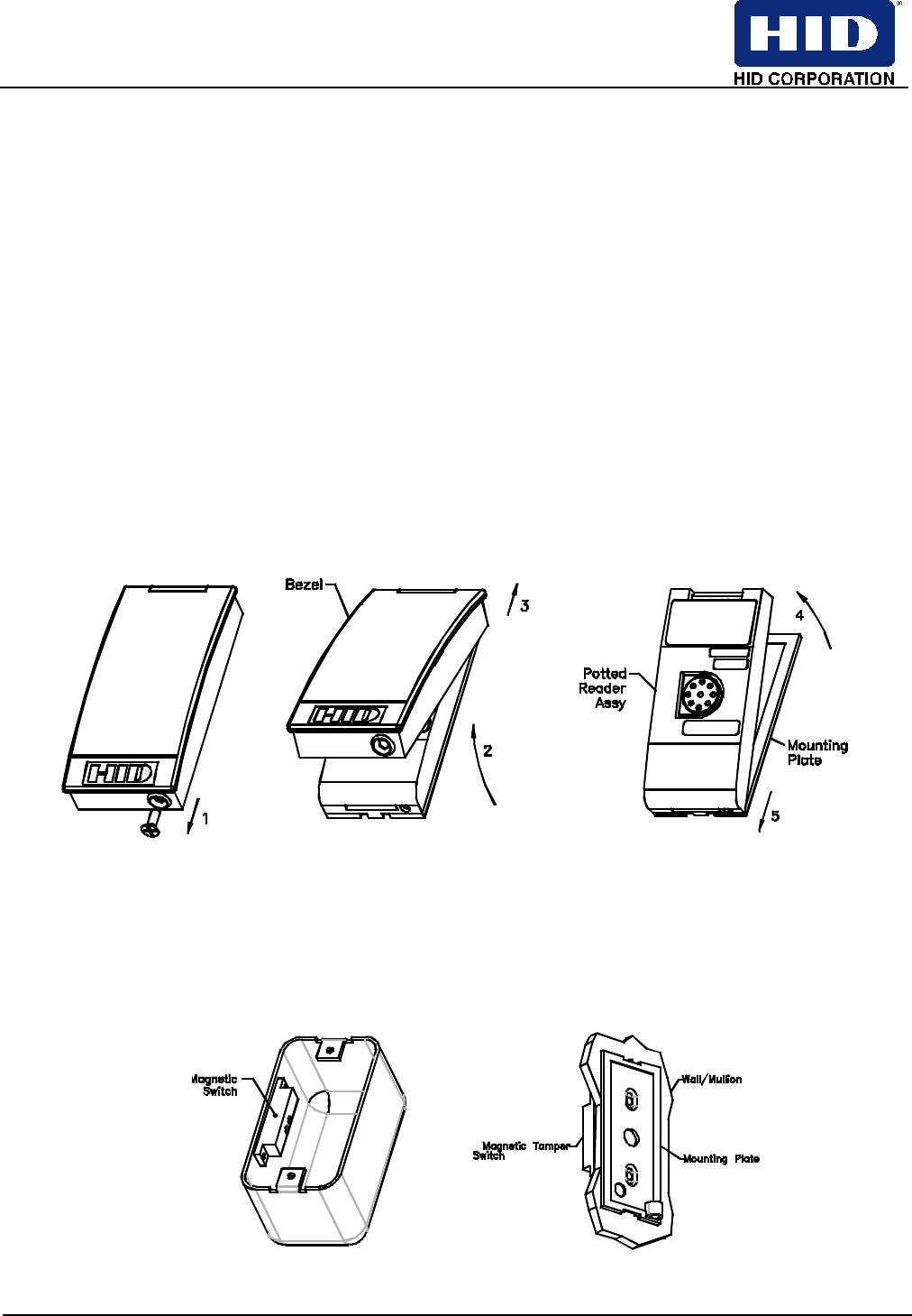
INSTALLATION
1- Disassemble
2 - Lift Bottom of Bezel 4 - Lift top of Reader Assembly
1- Remove Screw 3 - Slide Bezel up and remove 5 - Slide down and remove
2- Install Tamper Switch
An internal magnet provides tamper indication when used with a magnetic reed switch connected to an external alarm
system. (Except R10). Locate Switch behind the left side of the mounting plate, centered between the mounting holes.
Electrical Back Box Wall Surface
Installation Guide
iCLASS™ Reader Models R10, R30, R40, RW300, RW400
An ASSA ABLOY Group company ASSA ABLOY
_____________________________________________________________________________________________________
HID Corporation 9292 Jeronimo Road Irvine, CA 92618-1905 USA TEL (949) 598-1600 (800) 237-7769 FAX (949) 598-1690
Web page - www.hidcorp.com e-mail – tech@hidcorp.com iClass™ Reader Installation Manual 6090-900 Rev 8 Page 2 of 3
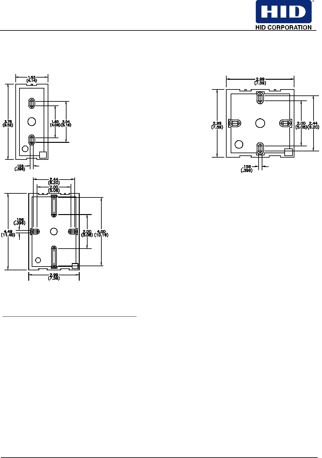
3- Preparing/Mounting
Install Mounting Plate to wall surface or back box, then reassemble reader (reverse Step 1 procedure).
Dimensions are in inches (centimeters).
R10 Mounting Plate R30/RW300 Mounting Plate R40/RW400 Mounting Plate
4- Connecting 5- Testing
Yellow *Speaker
Blue *Hold
• Turn Power On - watch the sign-on LED and hear the
speaker tones sequence.
Violet ***Open Collector
White Data 1
• Use a Test Card - watch for the LED flash and hear the
Speaker tone for each card read.
Green Data 0
Orange *Green LED 6- Optional Features
Brown *Red LED
Red +DC (10-16 VDC)
• RS232 interface/Host Mode - for applications requiring a
serial link. See Protocol Document 6090-902 for information
Black Ground
Gray ***RX (Serial Receive)
• Open Collector Output – controls an external device
(13.8VDC Max) operating in Host Mode only. See iCLASS
Application Note for details
Red/Green ***DSR (Not Used)
Pink ***TX (Serial Transmit)
• Configuration Options - Configure LED, Speaker, and other
features. See How To Order Guide or iCLASS Application
Note for details

Installation Guide
iCLASS™ Reader Models R10, R30, R40, RW300, RW400
An ASSA ABLOY Group company ASSA ABLOY
_____________________________________________________________________________________________________
HID Corporation 9292 Jeronimo Road Irvine, CA 92618-1905 USA TEL (949) 598-1600 (800) 237-7769 FAX (949) 598-1690
Web page - www.hidcorp.com e-mail – tech@hidcorp.com iClass™ Reader Installation Manual 6090-900 Rev 8 Page 3 of 3
Red/Yellow ***DTR (Not Used)
Drain **Shield Ground
• Hold Input – when asserted, this line either buffers a card
read or disables a card read until released, as configured.
* Optional Connections. ** Drain wire can be data return line when a separate power supply is used. *** Not used on R10, R30, R40
FCC WARNING:
This device complies with part 15 of the FCC rules. Operation is subject to the following two conditions: (1) this device may not
cause harmful interference, and (2) this device must accept any interference received, including interference that may cause
undesired operation. For proper regulatory compliance, the drain wire should not be connected to ground at the power supply
end of the cable. The reader is intended to be powered from a limited power source output of a previously certified power supply.
Changes or modifications not expressly approved by the party responsible for compliance could void the user's authority to
operate the equipment.