HID Global CX-8525 Proximity Reader, CX-8525 User Manual 330413
HID Global Corporation Proximity Reader, CX-8525 330413
Contents
- 1. Manual
- 2. Users Manual
Manual

06/05/03 330413.DOC REV. A I
CX-8525
Installation and Operation
Manual

06/05/03 330413.DOC REV. A II
FCC Compliance: This device complies with part 15 of the FCC Rules. Operation is subject to the
following two conditions: (1) This device may not cause harmful interference, and (2) this device must accept
any interference received, including interference that may cause undesired operation.
Changes or modifications not expressly approved by the party responsible for compliance could void the
user’s authority to operate the equipment.
Canadian Compliance: Operation is subject to the following two conditions: (1) this device may not cause
interference, and (2) this device must accept any interference, including interference that may cause
undesired operation of the device.
UL: The reader is intended to be powered from a limited power source output of a previously certified power
supply.
CE Compliance: Hereby, Indala, declares that this proximity reader is in compliance with essential
requirements and other relevant provisions of Directive 1999/5/EC.
Notice: The CX-8525 reader requires the use of linear, series pass, regulated power supplies. Use of
other types of power supply can result in reduced read range. The use of switching power supplies is
not recommended.
Do not use the reader's power supply for other equipment, particularly when operating switched inductive
loads such as motor control relays and solenoids (i.e., magnetic locks, latch or strike). Doing so will affect the
reader operation. Use a separate dedicated power supply for Indala proximity readers.
Because this technology is based on radio frequency and because nearby environmental sources of electrical
interference may affect the performance of the reader, below is a list of precautions that should be considered
when installing or wiring the reader:
• Metal affects radio signals. Do not cover the face of the reader with metal of any kind.
• Reduce or eliminate unwanted signals from external sources.
• Do not place the reader wiring bundled in conduit with AC power cables, lock power, or signal
wiring. Where possible.
• Maintain all reader wiring a minimum distance of 12" (30 cm) away from other wiring such as
AC power, computer data wiring, telephone wiring, or wiring to electric locking devices, etc.
• Avoid installing the reader in areas where sources of broad spectrum EMI noise may be present.
Examples of EMI broad spectrum noise producers are motors, pumps, generators, AC-DC
converters, uninterruptible power supplies, AC switching relays, light dimmers, computer
monitors, and CRTs
• Do not install the reader within 3.5' (1.1 m) of computer

06/05/03 330413.DOC REV. A III
Table of Contents
1.0 Product Specification .................................................................................................................................. 1
2.0 Introduction................................................................................................................................................ 2
2.1 Features.................................................................................................................................................................2
2.2 Theory of Operation.................................................................................................................................................2
2.3 Unpacking and Identifying Supplied Parts ..................................................................................................................3
3.0 Installation ................................................................................................................................................. 3
3.1 Mechanical Installation.............................................................................................................................................3
3.1.1 Gang Box Mounting (Preferred mounting Configuration).......................................................................................3
3.1.2 Wall Mounting ..................................................................................................................................................3
3.2 Electrical Installation ...........................................................................................................................................3
3.2.1 Reader Switch Settings ....................................................................................................................................3
3.2.2 Reader to Host Interface Cable Types and Lengths .............................................................................................4
3.2.3 Earth Grounding...............................................................................................................................................5
3.2.4 Reader to Host Interface Wiring .........................................................................................................................5
4.0 Operation................................................................................................................................................... 5
4.1 Presenting the Credential.........................................................................................................................................5
4.2 Data Output............................................................................................................................................................6
5.0 Controls and Indicators ............................................................................................................................... 6
5.1 LED and Beeper Control ..........................................................................................................................................6
6.0 Troubleshooting.......................................................................................................................................... 7
7.0 Copyrights, Patents, and Trademark Credits ................................................................................................. 8
8.0 RMA (Return Material Authorization) ............................................................................................................8
9.0 Contacting Customer Support ...................................................................................................................... 8
06/05/03 330413.DOC REV. A - 1 -
_____________________________________________________________________________________________
1.0 Product Specification
_____________________________________________________________________________________
¾ Input Voltage: 10 - 14 VDC at reader
¾ Input Current/Power:
o Off Metal 75 mA 0.9 W
¾ Power Supply:
o Recommendation Regulated linear power supply
¾ Read Range:
o With Indala Flexcard Up to 5.0" (12.7 cm)
¾ LED Indicator Three colors standard (red, green, amber)
¾ Audio Tone Standard, independently controllable
¾ Read Time (26 bit) 200 ms (from read to data output)
Programming
Switch selectable:
10 or 12 digit output
Unsupervised Magnetic Stripe F/2F
Supervised Magnetic Stripe F/2F
Silent Supervised Magnetic Stripe F/2F
¾ Frequency:
o Exciter Field 130 kHz
¾ Operating Temperature Range: -30° C to +65° C (-22° F to +149° F)
¾ Storage Temperature -40° C to +85° C (-40° F to +185° F)
¾ Material: Polycarbonate UL 94V0 rated
¾ Weight (typical): 5.1 oz. (144.6 g)
¾ Dimensions: 4.75”H x 2.9”W x .9”T
(12.07cm x 7.37 cm x 2.29 cm)
¾ Output Formats: Magnetic Stripe F/2F, Wiegand
¾ Approvals: UL294/cULus, FCC Certification – United States,
Canada Certification, CE Mark-Europe,
Australia C-Tick, New Zealand/EMC
Read range is stated in an undisturbed electrical environment, with card presented parallel to reader, and reader
installed in accordance with Indala instructions. Power supply, reader, and controller must be on the same ground,
connected to earth.
06/05/03 330413.DOC REV. A - 2 -
_____________________________________________________________________________________________
2.0 Introduction
_____________________________________________________________________________________________
The CX-8525 reader is a modular, miniaturized and rugged low power radio frequency reader designed
for applications where Magnetic Stripe F/2F output is required. The CX-8525 reader mounts on a USA
standard single electrical gang box or on any flat surface. Reader to host cable, Request to Exit, Door
Switch, and LED monitoring is available in Supervised and Silent supervised modes. The CX-8525
reader also includes an internal tamper switch for extra security. Control lines are provided for host
control of all three LEDs and he beeper.
2.1 Features
• Immediate audio and visual conformation of card read, host control not necessary.
• Independently controlled audio tone.
• Three LED indicators. (Red, Green, Amber)
• Switch selectable output formats:
o 12 digits for legacy systems or 10 digits for current systems.
o 26 Bit Wiegand
o Supervised Magnetic Stripe F/2F
o Silent Supervised Magnetic Stripe F/2F
• Internal Tamper Switch
• Mounting on USA standard single gang electrical box or on any flat surface.
• Indoor/outdoor operation.
• Attractive, contemporary styling.
2.2 Theory of Operation
When the reader is powered, a low-power radio frequency (RF) field is continuously transmitted by the
Reader (see Figure 1). When a card is presented within the field of the reader, the microchip, embedded
in the card, is activated and transmits a unique identification (ID) number back to the CX-8525 reader.
The reader decodes and converts this data to the pre-determined Wiegand, or Magnetic Stripe F/2F output
format and sends this code to an external controller through a data cable. With this information, the
controller determines what action is to be taken as a response to the card presentation. In Supervised
Mode the reader sends a message to the host that contains the status of the Door Switch, Green LED,
Request to Exit, and beeper while monitoring the data line for host acknowledgement of message
received. During Supervised and Silent Supervised operation, loss of connection with the controller will
cause the reader to enter Degraded Mode. Entering Degraded Mode with the reader in Supervised Mode
will cause the red LED to flash every two seconds and the Beeper to sound every thirty seconds.
Entering Degraded Mode while in Silent Supervised Mode will cause the reader to not respond to card
presentation and show no signs that the system has been degraded.
06/05/03 330413.DOC REV. A - 3 -
2.3 Unpacking and Identifying Supplied Parts
Unpack the equipment and become familiar with the components. The following list describes the
contents of the package.
Package Contents: CX-8525 Reader
Connector pigtail
Exterior mounting gasket
Installation guide
_________________________________________________________________________________________
3.0 Installation
_________________________________________________________________________________
3.1 Mechanical Installation
3.1.1 Gang Box Mounting (Preferred mounting Configuration)
The CX-8525 is designed to operate on a single USA gang box. If mounting directly on a metal surface other than a
gang box, insert a minimum 3/8” non-conductive spacer between the reader and the metal to prevent interference.
3.1.2 Wall Mounting
To mount the CX-8525 to a wall, drill a 0.375 hole for the reader cable. Feed the cable through the hole.
Place the reader against the wall and mark the location for the mounting holes. Drill the proper size
mounting holes (for 6-32 screws) at the marked location. Using 6-32 screws attach the reader back plate
to the wall. Assemble the reader onto the back plate and install the security screw.
3.2 Electrical Installation
3.2.1 Reader Switch Settings
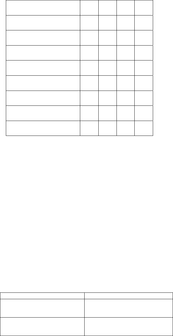
The CX-8525 reader has several output modes that can be set via the four position switch located on the
back of the reader under the back plate. The following table lists the valid switch settings for each reader
configuration.

06/05/03 330413.DOC REV. A - 4 -
Reader Configuration SW
1
SW
2
SW
3
SW
4
Unsupervised 10 digit
Output
OFF OFF OFF OFF
Unsupervised Legacy 12
digit output
ON OFF OFF OFF
Supervised 10 digit
Output
OFF ON OFF OFF
Supervised Legacy 12
digit output
ON ON OFF OFF
Silent Supervised 10 digit
Output
OFF ON ON OFF
Silent Supervised Legacy
12 digit output
ON ON ON OFF
Wiegand 10 digit output
OFF OFF OFF ON
Wiegand Legacy 12 digit
output
ON OFF OFF ON
3.2.2 Reader to Host Interface Cable Types and Lengths
The CX-8525 reader requires a minimum voltage of 10.0 VDC at the reader. Voltage drops,
caused by the cable resistance, can be made up by increasing the power supply voltage. DO
NOT SET THE POWER SUPPLY VOLTAGE TO HIGHER THAN 14 VDC!
Refer to the table below to determine the recommended wiring type at various maximum
distances. Because of system data termination differences, contact your system manufacturer for
its exact requirements. Installation should be in accordance with National Electric Code
ANSI/NFPA 70.
Cable Type Maximum Cable Length
24 AWG (0.60 mm), ten conductor,
with an overall foil shield, Belden
9540 or equivalent
500′ (152 m)
22 AWG (0.80 mm), ten conductor,
with an overall foil shield, Alpha
1299/10C or equivalent
500′ (152 m)

06/05/03 330413.DOC REV. A - 5 -
3.2.3 Earth Grounding
Connect the Power Supply and Controller directly to an earth ground. An earth ground can be established
by driving a copper clad ground rod into the earth. Make certain the DC resistance between your
established earth ground and the system ground is 50 Ohms or less.
3.2.4 Reader to Host Interface Wiring
The following table lists the connector to host wiring.
Connector
Pin
Description Pigtail Wire Color
1 +12 VDC RED
2 GROUND BLACK
3 RED LED CONTROL CLUE
4 GREEN LED CONTROL BROWN
5 YELLOW LED CONTROL ORANGE
6 DATA 0 GREEN
7 DATA 1 / F/2F WHITE
8 BEEPER CONTROL VIOLET
9 KEYING PIN
10 DOOR DIGITAL INPUT YELLOW
11 REX DIGIAL INPUT GRAY
_____________________________________________________________________________________________
4.0 Operation
_____________________________________________________________________________________
When power is first applied to the reader, it will flash the red, amber, and green LEDs and sound the
beeper once.
4.1 Presenting the Credential
To obtain maximum read range, present the card to the reader keeping the credential parallel to the reader,
move it slowly toward the face of the reader until a read confirmation is obtained. This is the point at
which the credential is read and the data is transmitted to the controller. To read the credential again,
remove it from the antenna field and present it again. During normal use, the credential can be presented
to the antenna at any angle, although this will result in a reduced read range.

06/05/03 330413.DOC REV. A - 6 -
4.2 Data Output
The CX-8525 reader is capable of outputting either Magnetic Stripe F/2F or Wiegand formatted data. For
further information please call technical support at (800) 646-3252 or (408) 361-4700.
_____________________________________________________________________________________
5.0 Controls and Indicators
_____________________________________________________________________________________
5.1 LED and Beeper Control
• The red, amber, green LEDs and the Beeper can be controlled by grounding their control
lines.
Connector Pin Signal Pigtail Wire
Color
3 Red LED Control Line Blue
4 Green LED Control Line Brown
5 Amber LED Control Line Orange
8 Beeper Control Line Violet
_____________________________________________________________________________________

06/05/03 330413.DOC REV. A - 7 -
6.0 Troubleshooting
_____________________________________________________________________________________
If the reader does not function properly when installed according to instructions, please complete this
form and fax it to (408) 361-4726 before calling (800) 646-3252 for technical assistance. International
customers call (408)361-4700:
FAX
From: ____________________________________________________ To: Technical Support
Phone: ___________________________________________________ Date: ___________
Fax: _____________________________________________________ Fax: (408) 361-4726_
Product S/N: ______________________________________________ Model: ____________
Sales order No. ____________________________________________ (S/O on Reader label)
Dead Reader
1. Is the reader wired according to instructions? o Yes o No
2. Is the recommended power supply being used? o Yes o No
3. Is the DC voltage correct at the reader? o Yes,__________ volts o No
4. Is the DC current correct? o Yes,__________ mA o No
5. What is the cable length between the power supply and the reader? ________feet
6. Is the cable type according to specifications? o Yes o No
Short Read Range
1. Is the reader wired according to instructions? o Yes o No
2. Is earth ground connected according to instructions? o Yes o No
3. Is the cable shield connected according to instructions? o Yes o No
4. Is the recommended power supply being used? o Yes o No
5. Is the DC voltage correct at the reader? o Yes,__________ volts o No
6. Is the DC current correct? o Yes,__________ mA o No
7. Is there a CRT (computer monitor) nearby? o Yes,__________ feet o No
8. Is the card presentation according to instructions? o Yes o No
9. Card model: __________________
Data Incorrect or Non-existent
1. At reader power up, did reader exhibit SelfTest ? o Yes o No
2. Upon card presentation, did reader exhibit QuickFlash ? o Yes o No
3. If you answered Yes to question 1 and 2, put the reader into line test mode
as detailed in section 7.5 "Verifying Data at Host".
4. Is the reader wired according to instructions? o Yes o No
5. Is earth ground connected according to instructions? o Yes o No
6. Is the cable shield connected according to instructions? o Yes o No
7. Is there a CRT (computer monitor) nearby? o Yes,__________ feet o No
8. Is the card presentation according to instructions o Yes o No
9. What is the reader format?___________________________ (Can be found on Reader label)
06/05/03 330413.DOC REV. A - 8 -
_____________________________________________________________________________________
7.0 Copyrights, Patents, and Trademark Credits
© 2002 Indala. Reserves all rights including patents, copyrights, trademarks, trade names, and all other
intellectual property rights worldwide. No reproduction, adaptation, or translation is allowed without prior
written permission from Indala. Indala reserves the right to change any product description and/or
specification contained here without prior notice.
Products are covered by United States patent 4818855, Canadian patent 1253591, and other patents
pending worldwide.
8.0 RMA (Return Material Authorization)
Returned merchandise will be accepted at the factory for repair, exchange or credit, at Indala’s election,
with an approved Return Material Authorization (RMA) number obtained from Indala Customer Service
prior to returning any product. The customer is to include serial numbers, formats, card ID numbers, and
correct facility codes with the items to be returned. The customer is to provide a description of the
specific problem. We require a minimum of 100 cards/tags/transponders for all RMA requests for
replacement. This minimum does not apply to “Returns” for Credit Only.
For readers returned and not covered by the warranty (due to age, misuse and/or damage), a quote for
repairs will be issued, and no work will be performed until a valid purchase order is received. Readers left
over 30 days without a repair authorization and a purchase order will be returned with evaluation charges
and shipping costs applied.
9.0 Contacting Customer Support
Please answer all questions in Section 10.0 "Troubleshooting" and have your answers ready before you
call the Technical Support number listed below:
Corporate Headquarters
6850 B Santa Teresa Blvd.
San Jose, CA 95119-1205
Tel (408) 361-4700,Main
Tel (800) 646-3252, Technical Support
Fax (408) 361-4726
European Office:
Unit 2, Anvil Court
50 Denmark Street
Wokingham, Berkshire,
RG40 2BB United Kingdom
Tel: +44 (0) 1189-121-780
Fax: +44 (0) 1189-121-790