HID Global CX-8525 EM Reader 1 User Manual 377368
HID Global Corporation EM Reader 1 377368
Contents
- 1. Manual
- 2. Users Manual
Users Manual
K02008-001 REV. A 1
EM Reader Installation and Operation Guide
1.0 Overview
1.1 Introduction
The EM Reader is designed to read and report EM compatible 4000 and 4100 series “read only”
credentials in 26 bit Wiegand format. The reader supports credentials programmed in either F/32 or
F/64 data rates and data coded as Manchester. A bi-color LED and beeper provide visual and audible
confirmation of power and data delivery to the host.
1.2 Unpacking and Identifying Supplied Parts
Unpack the contents and become familiar with the components. The following items will be included with
the EM readers:
1. Installation guide
2. EM Reader
3. Housing label cover
2.0 Installation
2.1 Mechanical Installation
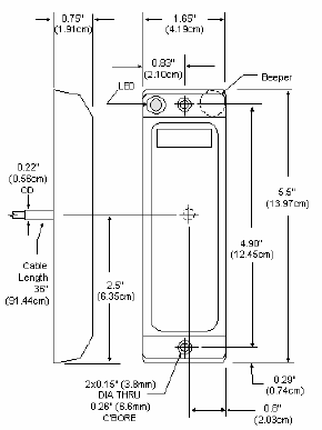
2.1.1 Mounting
EM readers mount to a door frame by drilling two holes sized for 6-32, or M-3 sheet metal or thread-
forming screws 4.92” (125mm) separation. Locate and drill a 0.375” (0.95 cm) hole for the reader cable.
See drawing below for details.
Route the cable through the center hole to the controller. Using the two 6-32 or M-3 screws attach the
reader to the two mounting holes.
K02008-001 REV. A 2
2.2 Power Supply Cable Types and Maximum Lengths
The EM Reader requires a minimum voltage of 8.0 VDC. Voltage drops caused by the cable resistance,
can be made up by increasing the power supply voltage (DO NOT SET THE POWER SUPPLY
VOLTAGE TO HIGHER THAN 14 VDC). The following are the recommended cable types and maximum
cable lengths for cable connecting the power supply to the reader (DO NOT USE CABLES WITH
GAUGES SMALLER THAN 24 AWG):
Cable Type
Maximum Cable Length
24 AWG (0.60mm), three conductors, with an
overall foil shield, Belden 9533 or equivalent.
200’ (61 m)
22 AWG (0.80mm), two conductors, with an overall
foil shield, Alpha 5192 or equivalent.
300’ (91 m)
18 AWG (1.20mm), two conductors, with an overall
foil shield, Alpha 5836 or equivalent.
500’ (152 m)
2.2.1 Reader to Host Interface Wire Types and Lengths
Refer to the table below to determine the recommended wiring type at various maximum distances.
Variation in distance requires different wire gauges, Because of system data termination differences,
contact your system manufacturer for its exact requirements, Installation to be in accordance with
National Electric Code ANSI/NFPA 70.
Cable Type
Maximum Cable Length
22 AWG (0.80mm), six or eight conductor, with an
overall foil shield, Alpha 5196, 5198 or equivalent.
500’(152 m)
18 AWG (1.20mm), six or eight conductor, with an
overall foil shield, Alpha 5386, 5388 or equivalent.
500’ (152m)
Readers Power Supply
Cable Length
Readers Power Supply
Cable Length
K02008-001 REV. A 3
2.3 Electrical Installation
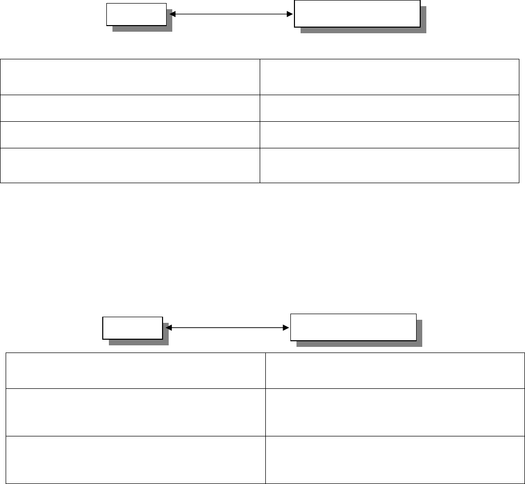
2.3.1. Grounding
EM Reader
EM Reader
Earth
Ground
GND
Host
Controller
Linear
Power
Supply
Connect the reader directly to an earth ground. An earth ground can be established by driving a copper-
clad ground rod into the earth. Make certain the DC resistance between your established earth ground
and the system ground is 50 Ohms or less. If direct connection to a ground rod is not possible, connect
the reader to an earth-grounded cold water metal pipe (do not connect to copper fire sprinkler system
because it may have non-conductive couplings) or steel frames (building beams) that connect to earth.
In single or multiple reader installations, connect all readers to a single earth ground reference point.
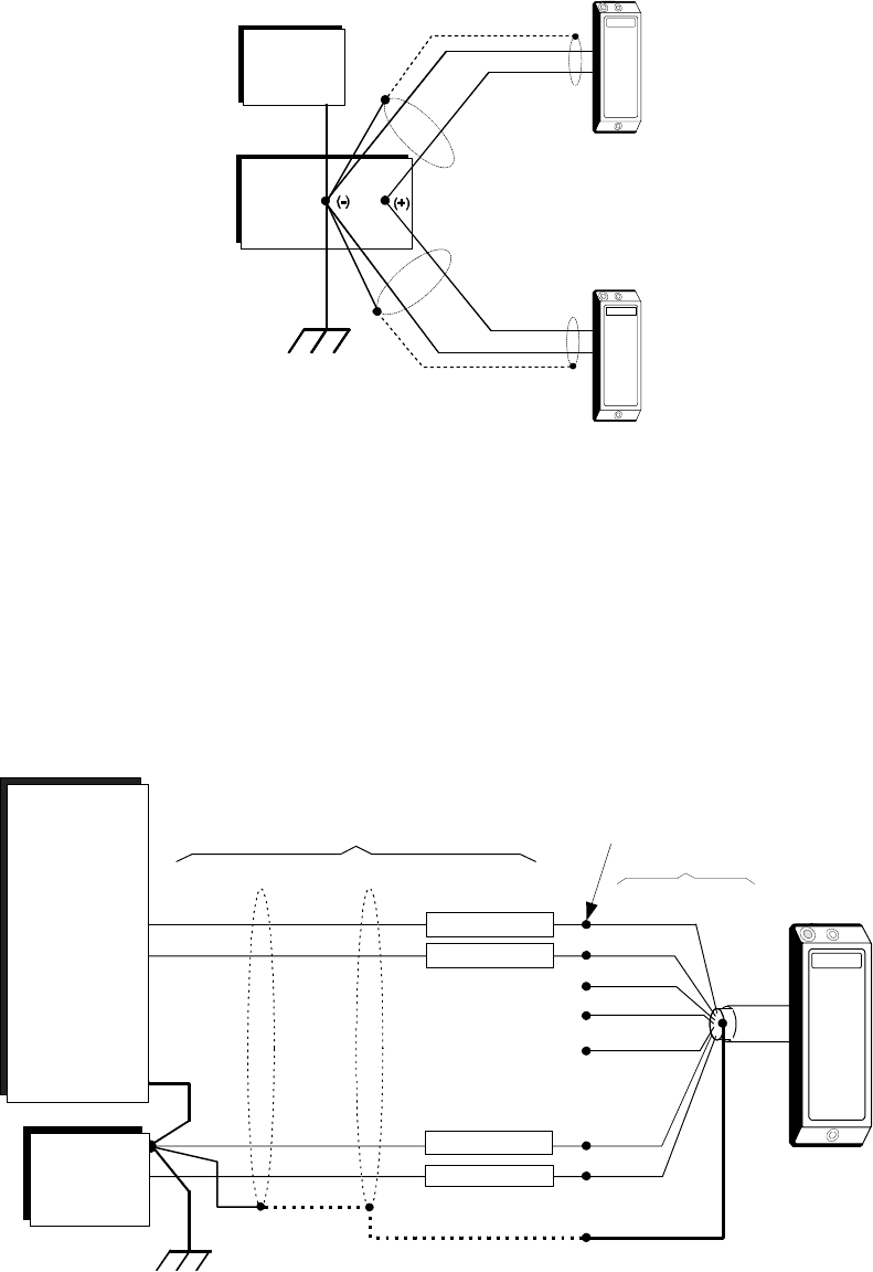
2.3.2. Reader to Host Interface Wiring
EARTH GROUND
Linear
Power
Supply
+
-
Host
Controller
Wiegand
Suggested
Color Code
(White)
Color
Code
Reader Cable
Green
Brown
Black
Red
White
Splice Here
Extension Cable
Shield (Screen)
Data '1' In
Data '0' In
EM
reader
Blue
Orange
GND
(Green)
Do not use
(Red)
Do not use
Do not use
(Black)
Notes:
• The system must have a single earth ground point.

K02008-001 REV. A 4
• The Shield wire is not terminated within the reader.
3.0 Operation
When power is first applied to the reader, it performs an internal circuit check. If it is functioning properly, the
reader will flash the Green LED, beep three times, enter ready mode, and display the Red LED.
3.1 Presenting the Card
To obtain maximum read range, present the card to the reader (keeping the card parallel to the reader),
and move it toward the face of the reader until the reader beeps and flashes. This indicates that the
card has been read and data has been transferred to the host.
Data Output
The Reader outputs in 26-bit Wiegand format only.
4.0 Specifications
Operating Voltage Range 8 VDC – 14 VDC
Absolute Maximum 14 VDC
Average Current VDC (maximum) 80 mA
Read and Report Speed (Wiegand) 500 mSec
Wiegand Data Pulse Widths 20µSec -- 100µSec (40.5µSec default)
Wiegand Data Interval 200µSec --10mSec (2mSec default)
Any Card Lockout Delay 500 mSec
5.0 Regulatory
FCC Compliance: This device complies with part 15 of the FCC Rules. Operation is subject to the
following two conditions: (1) This device may not cause harmful interference, and (2) this device must
accept any interference received, including interference that may cause undesired operation.
Changes or modifications not expressly approved by the party responsible for compliance could void the
user’s authority to operate the equipment.
Canadian Compliance: Operation is subject to the following two conditions: (1) this device may not
cause interference, and (2) this device must accept any interference, including interference that may
cause undesired operation of the device.
UL: The reader is intended to be powered from a limited power source output of a previously certified
power supply.
CE Compliance: Hereby, Indala, declares that this proximity reader is in compliance with essential
requirements and other relevant provisions of Directive 1999/5/EC.