HID Global MI100 Mifare 100 Series Reader User Manual 468165
HID Global Corporation Mifare 100 Series Reader 468165
Users Manual

K02013-000 Rev. A Page 1 of 5 06/08/04
Indala MIFARE Slim Reader
Indala MIFARE Wallswitch Reader
MI100-xxxA
Installation & Operating Manual

K02013-000 Rev. A Page 2 of 5 06/08/04
FCC
This device complies with part 15 of the FCC rules. Operation is subject to the following two conditions:
(1) this device may not cause harmful interference, and (2) this device must accept any interference
received, including interference that may cause undesired operation.
Changes or modifications not expressly approved by the party responsible for compliance could void the
user’s authority to operate the equipment.
(HID Readers and others in certain cases where shielded cable is used) For proper regulatory compliance,
the drain wire should be disconnected at the power supply end of the cable.
UL
This Proximity Reader is intended to be powered from a limited power source output of a previously
certified power supply.
K02013-000 Rev. A Page 3 of 5 06/08/04
1.0 Parts List
PARTS LIST (Included) Quantity
- MI100-xxxA reader with snap-on bezel and 3 meter cable. 1
- Security screw 1
- Installation manual 1
Not included parts required for installation are wire splices, linear power supply (12V, 100mA), and etc…
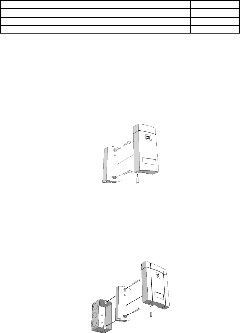
2.0 Mounting Instructions
Mullion Mounting
To mount the MI100-xxxA reader to a mullion, drill two proper size holes (for 6-32 sheet metal or
thread forming screws) 3.3" apart. At center of these two holes drill a 0.375" hole for the reader cable.
Route the cable through the center hole to the controller. Remove the security screw to separate the
bezel from the reader to install the reader onto the mullion using two 6-32 screws. Once the reader
module is screwed in place, snap on the reader bezel and re-install the security screw.
Figure 1- Mullion Mounting
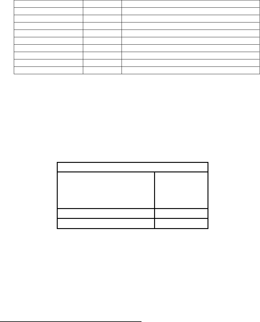
Wall Mounting
To wall mount the reader there are two choices. The first choice is to mount the reader directly to the
wall. This is similar to the mullion mounting described above. The second choice is to mount it on a
gang box. When installing the reader on an electrical gang box, make sure the gang box mounting
holes fit the reader mounting holes. Remove the security screw to separate the bezel from the reader to
install the reader to the gang box using two 6-32 screws as shown. Once the reader module is screwed
in place, snap on the reader bezel and re-install the security screw.
Figure 2 - Wall Mounting
K02013-000 Rev. A Page 4 of 5 06/08/04
3.0 Connecting the Reader
• Connect the reader to the host controller per the wiring table below and the host installation guide.
Wire Color Symbol Name/Function
Red (input) V+ Positive Supply Voltage.
Black (input) V- Return Power (Common) Line.
Drain (input) GND Earth Ground.
Foil Shield (input) GND Cable Shield.
White (output) “1” Wiegand Data 1.
Green (output) “0” Wiegand Data 0.
Blue (input) Beeper Control Line.
Brown (input) Red LED Control Line.
Orange (input) Green LED Control Line.
The followings are required to comply with FCC and EU RF emission standards: drain wire and foil shield
can be connected either separately to earth ground and the return power (common) line respectively or all
together while the earth ground and return power (common) line are tied together at the power supply.
4.0 Testing and Operation
• When power is applied to the reader, the red LED is on under the default setting.
• Present an ID card to the reader. The LED will momentarily turn green while the beeper beeps once,
indicating that the card was read successfully.
• Please note that typical read range for MIFARE (1K & 4K) cards is 1.0 – 1.5” (25-37mm).
Important Product Specifications
Power supply
Absolute Maximum Voltage
Maximum Current at 12V
Operating Voltage Range
Linear type
14 VDC
60mA
10.0 – 14.0 VDC
Maximum cable distance to host 500 ft Wiegand
Operating temperature range -30 to 65°C
5.0 Card Compatibility
• The MI100-xxxA reader reads the card serial number (CSN) data from these cards:
• Indala MIFARE Card, Part No. MIFxx-xxxxxxx-yyyy
• Indala MIFARE/Proximity Part No. FPMIF-xxxxxx-yyyy (dual technology)
• Any Philips compatible MIFARE Standard (1K & 4K) contactless smart card.
• The Indala MIFARE reader will not read 125 kHz Indala Proximity cards.
6.0 Reader Operation
Card Serial Number (CSN) Read Only Mode
• In CSN only mode, the reader reads the 32-bit MIFARE random card serial number (CSN or UID)
from any MIFARE standard (1K & 4K) card and outputs that data in a 40-bit Wiegand format: 32-bit
CSN + 8 bit checksum.

K02013-000 Rev. A Page 5 of 5 06/08/04
Sector Read Only Mode
• In Sector Read Only Mode the reader reads and outputs a specified number of bits from a specified
sector based on a custom configuration of the reader. The following reader attributes can be configured
at the factory to meet individual needs:
1. Application sector (0 – 15 or 39 depending on 1K or 4K card)
2. Application block (0-2)
3. Sector keys
4. Number of output bit (1-128)
5. Starting bit number (0-127)
6. Error-Tone on invalid card/application
7. Audio/Visual feedback (On/Off)
Contacting Indala
6850 Santa Teresa Blvd.
San Jose, CA 95119-1205
Main Phone: 408 361-4700
Main Fax: 408 361-4701
US Toll-Free: 800 779 8663 (Sales); 800 646 3252 (Technical Support)
Web address: www.indala.com