HID Global SMARTID SmartID 803xD User Manual
HID Global Corporation SmartID 803xD Users Manual
Users Manual

SmartID and Sma
r
INSTALLAT
I
Document Number 803
0
© 2008 HID GLOBAL CORPORATION. A
L
9292 Jeronimo Road
Irvine, CA 92618-1905

Page 2 of 19 February 13, 2008
© 2008 HID Global Corporation. All rights reserved.
SmartID Proximity Reader - 8030-901, Rev A.0
February 13, 2008
© 2008 HID Global Corporation. All rights res
e
SmartID Proximity Reader - 8030-901, Rev A.0
7 Contacts
Americas
HID Global Corporation (California, USA)
Email: tech@hidcorp.com
Main: (949) 598-1600
Support: 1-800-237-7769
Fax: (949) 598-1690
Europe, Middle East and Africa
HID Global Corporation, Ltd. (Haverhill, UK)
Email: eusupport@hidcorp.com
Main: +44 (0) 1440 714 850
Support: +44 (0) 1440 711 822
Fax: +44 (0) 1440 714 840
Asia-Pacific
HID Global Corporation Asia Pacific Ltd. (Hong Kong)
Email: asiasupport@hidcorp.com
Main: (852) 3160 9800
Support: (852) 3160 9802
Fax: (852) 3160 4809

Page 18 of 19 February 13, 2008
© 2008 HID Global Corporation. All rights reserved.
SmartID Proximity Reader - 8030-901, Rev A.0
6.5 DGT/NCC
經型式認證合格之低功率射頻電機,非經許可,公司、商號或使用者均不得擅自變
更頻率、加大功率或變更原設計之特性及功能。低功率射頻電機之使用不得影響飛
航安全及干擾合法通信;經發現有干擾現象時,應立即停用,並改善至無干擾時方
得繼續使用。前項合法通信,指依電信法規定作業之無線電通信。低功率射頻電機
須忍受合法通信或工業、科學及醫療用電波輻射性電機設備之干擾。
According to "Administrative Regulations on Low Power Radio Waves Radiated
Devices" Without permission granted by the DGT, any company, enterprise, or
user is not allowed to change frequency, enhance transmitting power or alter
original characteristic as well as performance to a approved low power radio-
frequency devices. The low power radio-frequency devices shall not influence
aircraft security and interfere legal communications; If found, the user shall cease
operating immediately until no interference is achieved. The said legal
communications means radio communications is operated in compliance with the
Telecommunications Act. The low power radio-frequency devices must be
susceptible with the interference from legal communications or ISM radio wave
radiated devices.
February 13, 2008
© 2008 HID Global Corporation. All rights res
e
SmartID Proximity Reader - 8030-901, Rev A.0
Contents
1 Products List..................................................................
.
2 Overview ........................................................................
.
2.1 Mullion Mounting.................................................
.
2.2 Indications ..........................................................
.
2.3 Connections........................................................
.
2.4 Output Protocols.................................................
.
2.5 Security...............................................................
.
3 Specifications ................................................................
.
4 Timing.............................................................................
.
5 Installation Instructions................................................
.
5.1 Wall Mounting Drawing (All Models)...................
.
5.2 Conductor Connections (All Models) ..................
.
5.3 Tamper Switch - Optional ...................................
.
5.4 Switch Box Mounting Plate - Optional.................
.
5.5 Mullion Reader Mounting Plate – Spacer ...........
.
6 Regulatory......................................................................
.
6.1 UL.......................................................................
.
6.2 FCC / Canada Radio Certification.......................
.
6.3 CE Marking.........................................................
.
6.4 Asia and Pacific Rim...........................................
.
6.5 DGT/NCC ...........................................................
.
7 Contacts.........................................................................
.
List of Figures
Figure 1 Mullion Mounting............................................................
.
Figure 2 Tamper Switch ...............................................................
.
Figure 3 Mounting Plate Step 1 and 2..........................................
.
Figure 4 Mounting Plate Step 3 and 4..........................................
.
Figure 5 Mounting Plate Spacer...................................................
.
Page 4 of 19 February 13, 2008
© 2008 HID Global Corporation. All rights reserved.
SmartID Proximity Reader - 8030-901, Rev A.0
1 Products List
This guide is applicable for the following SmartID and SmartTRANS products:
HID Part
Number HID Model Description
*8030xyzz S10 SmartID Mullion Reader
*8045xyzz SK10 SmartID Mullion Keypad Reader
**8100xyzz SP10 SmartTRANS Mullion Reader with HID/AWID Prox
**8110xyzz SPK10 SmartTRANS Mullion Keypad Reader with HID/AWID Prox
***8140xyzz
SP10 SmartTRANS Mullion Reader with Indala Prox
***8141xyzz
SPK10 SmartTRANS Mullion Keypad Reader with Indala Prox
Notes: ‘x’ = Revision of Main Board, ‘y’ = color of plastic housing and ‘zz’ = application
* UL Listed to UL 294.
** ETL Listed to UL 294 – UL Listing to UL 294 Pending.
*** UL Listing Pending.
Accessories:
HID Part
Number Manual
Section Description
500-0300 5.3 Tamper Switch
500-8090 5.4 Mullion SPMD – Switch Box Mounting Plate
500-9287 5.5 Mullion Reader Mounting Plate – Spacer
The accessories are not listed to UL294.
Accessories are compatible with all readers in this manual.
February 13, 2008
© 2008 HID Global Corporation. All rights res
e
SmartID Proximity Reader - 8030-901, Rev A.0
6 Regulatory
6.1 UL
These proximity readers are intended to be powered from
a
output of a previously certified power supply. These reader
s
used with listed (UL294) control equipment.
6.2 FCC / Canada Radio Certification
These devices comply with part 15 of the FCC rules.
Operation is subject to the following two conditions: (1) Thi
s
harmful interference, and (2) This device must accept any i
including interference that may cause undesired operation.
modifications not expressly approved by the party responsi
void the user's authority to operate the equipment.
Le fonctionnement est soumis aux deux conditions suivant
e
peut pas causer de perturbations nuisibles et (2) ce disposi
perturbation quelconque qu’il reçoit, y compris des perturb
a
provoquer un fonctionnement indésirable. Les changemen
t
n’ayant pas été expressément approuvés par la partie res
p
conformité peuvent faire perdre à l’utilisateur l’autorisation
d
matériel.
This Category II radiocommunication device complies wi
t
Standard RSS-310.
Ce dispositif de radiocommunication de catégorie II resp
e
d’Industrie Canada.
The Carrier Frequencies and output power are as follows :
803xD, 810xD 13.56MHz -6.
5
810xD 125kHz <-4
d
6.3 CE Marking
HID Global hereby declares that these proximity readers a
r
essential requirements and other relevant provisions of Dir
e
6.4 Asia and Pacific Rim
Pending

Page 16 of 19 February 13, 2008
© 2008 HID Global Corporation. All rights reserved.
SmartID Proximity Reader - 8030-901, Rev A.0
5.5 Mullion Reader Mounting Plate – Spacer
The sizes in the drawing are in millimeters, 1 mm is 0.039 in.
Figure 5 Mounting Plate Spacer
February 13, 2008
© 2008 HID Global Corporation. All rights res
e
SmartID Proximity Reader - 8030-901, Rev A.0
2 Overview
The SmartID 13.56MHz and SmartTRANS 13.56MHz + 12
slim door mountable design to match any installation envir
o
LED’s and buzzer allow the SmartID Readers to be mount
e
The SmartID reader accepts 5 to 24 Volts DC. The reader
o
Wiegand, Clock-and-Data (Magstripe ABA / ISO7811), RS
2
hardware interfaces.. The 5 Volt DC capabilities allow the r
e
reader systems without rewiring or pulling new cables. The
high reliability, consistent read characteristics and low pow
e
The SmartID reader family includes RS232/RS422/RS485
read-only and read/write operations.
Standard capabilities include host system controlled red an
buzzer.
2.1 Mullion Mounting
Ideally suited for mullion-mounted door installations or any
f
not cover junction box). An optional single-gang electrical
b
available.
2.2 Indications
When a card is read successfully, the card data is sent to t
h
buzzer sounds a short 3KHz beep. Both LED’s and the bu
z
by the host system.
2.3 Connections
The SmartID reader family has a flexible and reliable conn
e
space for the cable and the connector within the SmartID h
o
with silicone to withstand harsh environmental conditions.
2.4 Output Protocols
The SmartID reader family operates with any facility, syste
m
scheme. The data output format, contents and length are d
personalization of the card or configuration of the reader.
The readers are intended for connection to an Access Con
t
compatibility to the reader is referenced in the control unit’s
2.5 Security
The SmartID reader family offers high security challenge r
e
protect the RFID air interface against various attack schem
e
playback attacks.
Page 6 of 19 February 13, 2008
© 2008 HID Global Corporation. All rights reserved.
SmartID Proximity Reader - 8030-901, Rev A.0
3 Specifications
PRODUCT INPUT
VOLTAGE POWER OPERATING
TEMPERATURE CABLE
DISTANCE
SmartID
5-24 VDC Avg 600 mW
Peak 1000 mW
-22° - 140°F
(-30° - 60° C)
Wiegand
500 ft - 18 AWG
(153 m)
300 ft - 20 AWG
(91 m)
200 ft - 22 AWG
(61 m)
Clock-and-Data
82 ft - 22 AWG
(25 m)
RS232
50 ft (15.24 m)
RS485
4000 ft (1,219.2 m)
Recommended cable type:
Stranded conductor with overall
stranded shield or equivalent.
SmartTRANS
HID / AWID
Avg 1400 mW
Peak 2100 mW
February 13, 2008
© 2008 HID Global Corporation. All rights res
e
SmartID Proximity Reader - 8030-901, Rev A.0
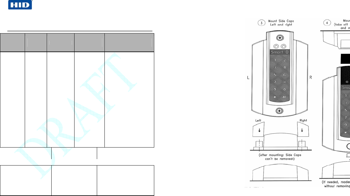
Figure 4 Mounting Plate Step 3 and 4
Page 14 of 19 February 13, 2008
© 2008 HID Global Corporation. All rights reserved.
SmartID Proximity Reader - 8030-901, Rev A.0
5.4 Switch Box Mounting Plate - Optional
The sizes in the drawing are in millimeters, 1 mm is 0.039 in.
Figure 3 Mounting Plate Step 1 and 2
February 13, 2008
© 2008 HID Global Corporation. All rights res
e
SmartID Proximity Reader - 8030-901, Rev A.0
SmartTRANS
Indala Prox
Avg 1300
m
Peak 160
0
3.1.1 ISO Card Read Range
ISO14443 up to 1.6 in (4 cm)
DESFire up to 1.6 in (4 cm)
3.1.2 Interface
Inputs EMC Prot. 10K ohm pull-ups
Outputs EMC Prot. open drain 0.5 A/max
3.1.3 Wiegand Signal Levels
Voh = Output Voltage idle high
Vol = Output Voltage active low

Page 8 of 19 February 13, 2008
© 2008 HID Global Corporation. All rights reserved.
SmartID Proximity Reader - 8030-901, Rev A.0
3.1.4 Reader Output Interface and Pull-up Resistors
The SmartID readers provide true open collector outputs for Wiegand, Clock-and-
Data, ABA track 2 emulation, meaning the data output is not voltage driven.
External pull-up resistors are required when the controller does not provide internal
pull-up resistors. The typical value for the pull-up resistors is 1kOhm. The
recommended position to place the pull-up resistors is at the controller side.
The pull-up resistor #1 connects form Data/D1 (reader connector pin 3) to a 5 volt
reference.
The pull-up resistor #2 connects form Clock/D0 (reader connector pin 4) to a 5 volt
reference.
February 13, 2008
© 2008 HID Global Corporation. All rights res
e
SmartID Proximity Reader - 8030-901, Rev A.0
5.3 Tamper Switch - Optional
Figure 2 Tamper Switch
Page 12 of 19 February 13, 2008
© 2008 HID Global Corporation. All rights reserved.
SmartID Proximity Reader - 8030-901, Rev A.0
5.2 Conductor Connections (All Models)
Clock-in-Data
(ABA) Wiegand RS232 RS422 RS485
1 Green LED input Green LED input Green LED
input** Green LED
input** Green LED
input**
2 Red LED input Red LED input Red LED input** Red LED input** Red LED input**
3 Data D1 Do not connect TXA TRX
4 Clock D0 TXD TXB TRX
5 Buzzer input Buzzer input Do not connect RXA Do not Connect
6 Do not Connect Do not Connect RXD RXB Do not Connect
7 Ground Ground Ground Ground Ground
8 Power
5 to 24VDC
Power
5 to 24VDC
Power
5 to 24VDC
Power
5 to 24VDC
Power
5 to 24VDC
CAUTION: 5 VDC is minimum voltage at reader connector pins.
Tamper contact (optional): rating 1A 30 VDC.
** LED input only valid in read-only applications.
February 13, 2008
© 2008 HID Global Corporation. All rights res
e
SmartID Proximity Reader - 8030-901, Rev A.0
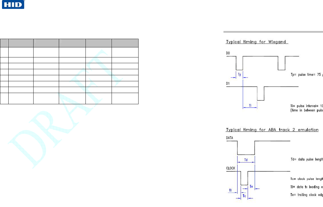
4 Timing

Page 10 of 19 February 13, 2008
© 2008 HID Global Corporation. All rights reserved.
SmartID Proximity Reader - 8030-901, Rev A.0
5 Installation Instructions
1. Drill two holes for mounting the reader (see Figure 1 Mullion Mounting, page
7). Do not mount readers less than 20 cm (7.87 in) from each other. Make
sure that enough room to connect the cable is allowed. Protect the cable
against sharp edges and any damage from chaffing.
2. Remove the Terminal Connector 8 pin from the back of the reader. Use a
small flat head screwdriver to loosen all terminals. The end of the cable
should be prepared by cutting it back to expose the wires and each end
should be twisted to eliminate any loose or frayed wires.
3. Connect the wires to the reader inline with the connector assignments. Wire
ends outside the shielding and optional permanent LED links should be kept
as short as possible. Twist the connector a few times to twine the wire ends
avoiding differential mode interference on the data lines.
Note: Wires at the connector must be kept as short as possible: long, unshielded
connections will reduce the sensitivity of the reader.
4. After wiring the reader and the Host system, the reader is ready to be
tested. Apply power and present a card to the reader. The green LED
should flash and the buzzer should beep indicating a read. If the Host
system is connected to the red and green LED inputs these should follow
the functionality of the Host system.
5. Secure the reader using the appropriate screws. Mount the black cover
(sticker) and mount the cap over the mounting hole.
February 13, 2008
© 2008 HID Global Corporation. All rights res
e
SmartID Proximity Reader - 8030-901, Rev A.0
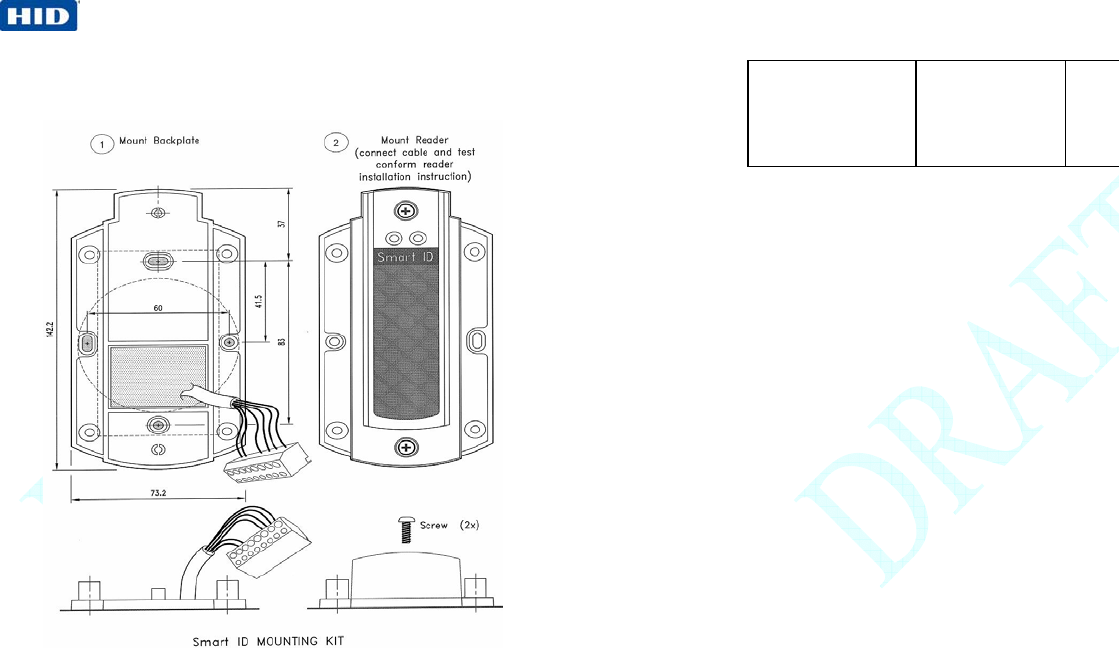
5.1 Wall Mounting Drawing (All Mode
The drawing dimensions are in millimeters. 1 mm equals 0.039 inc
h
Figure 1 Mullion Mounting