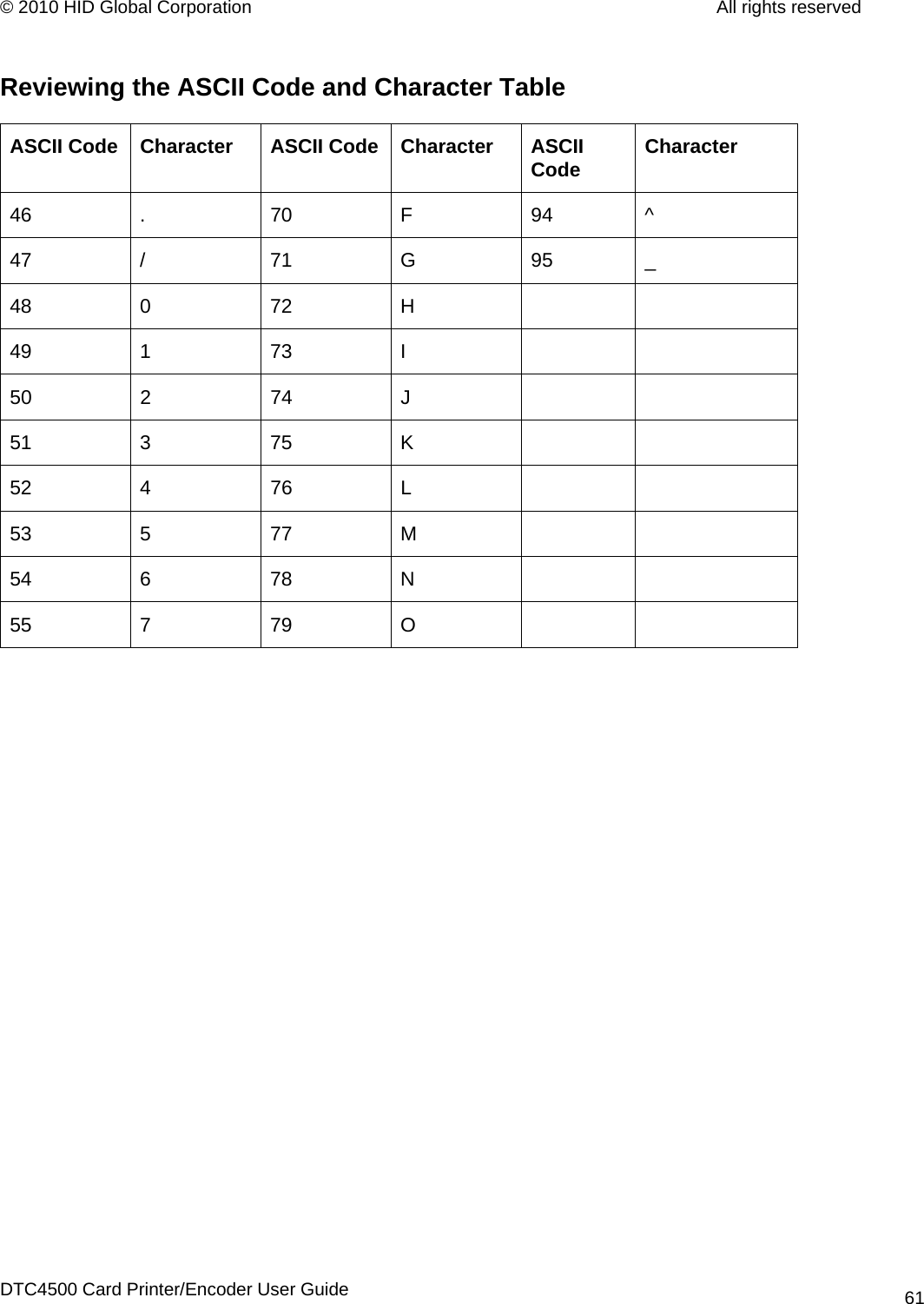
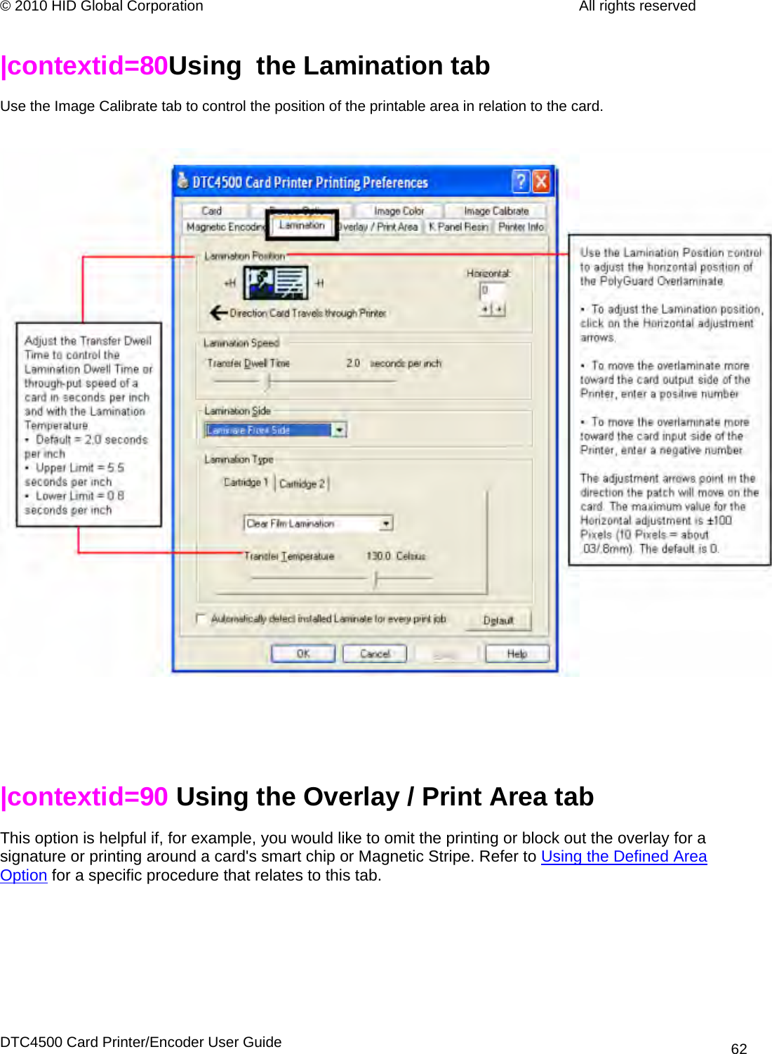
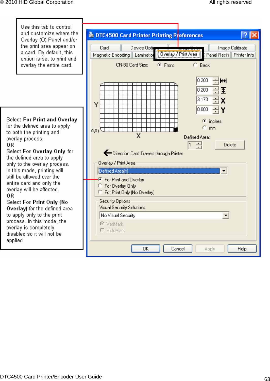
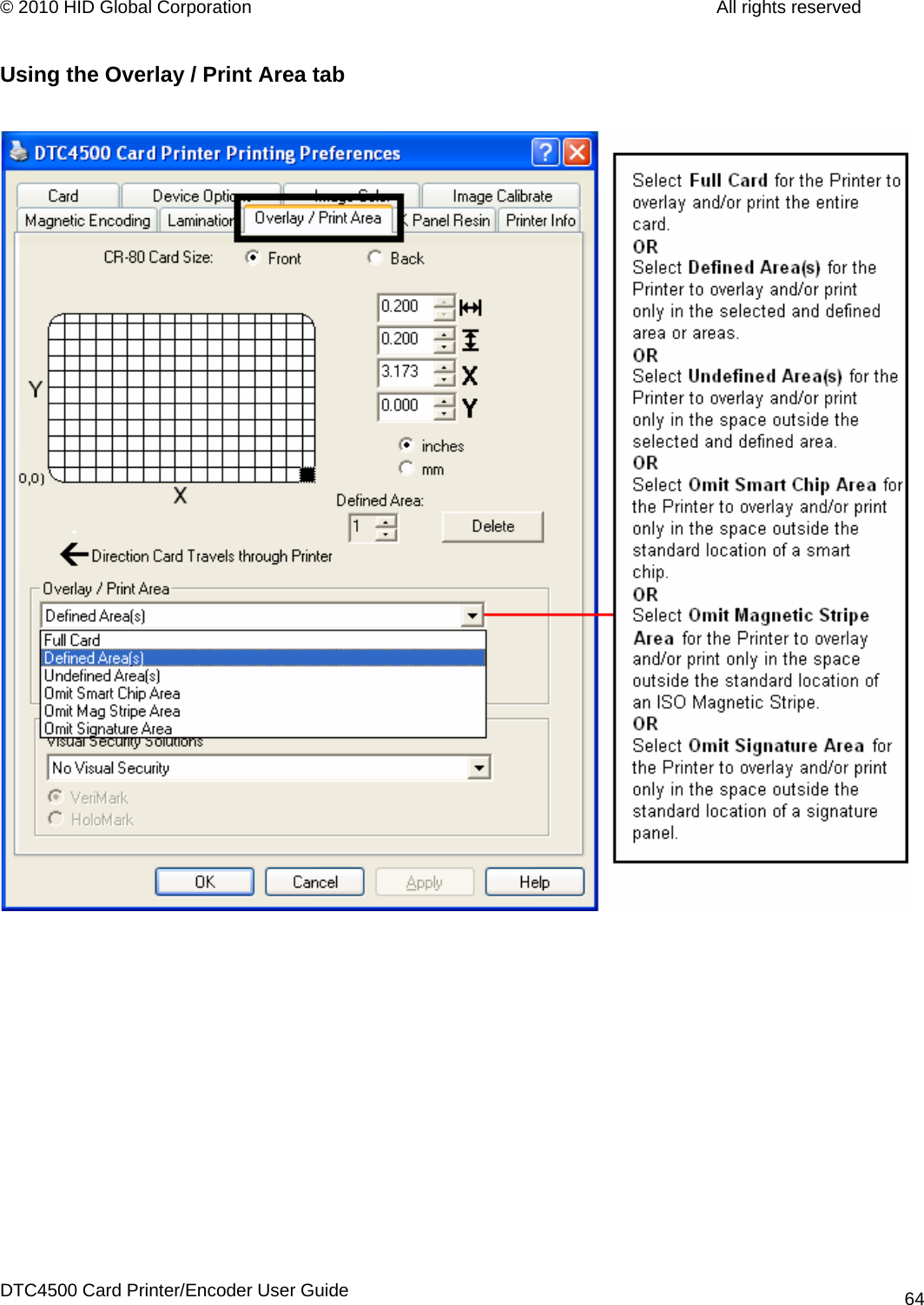
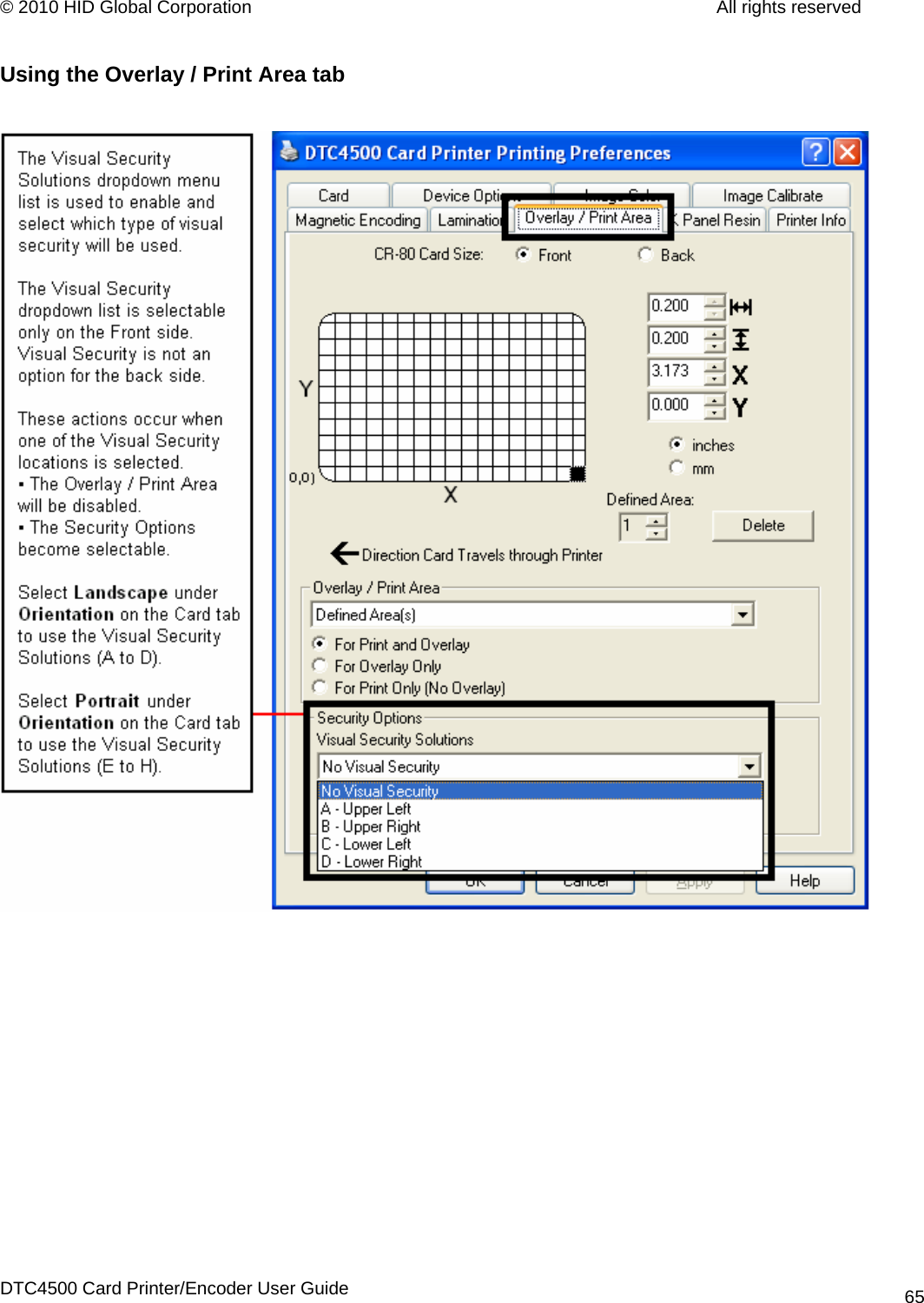
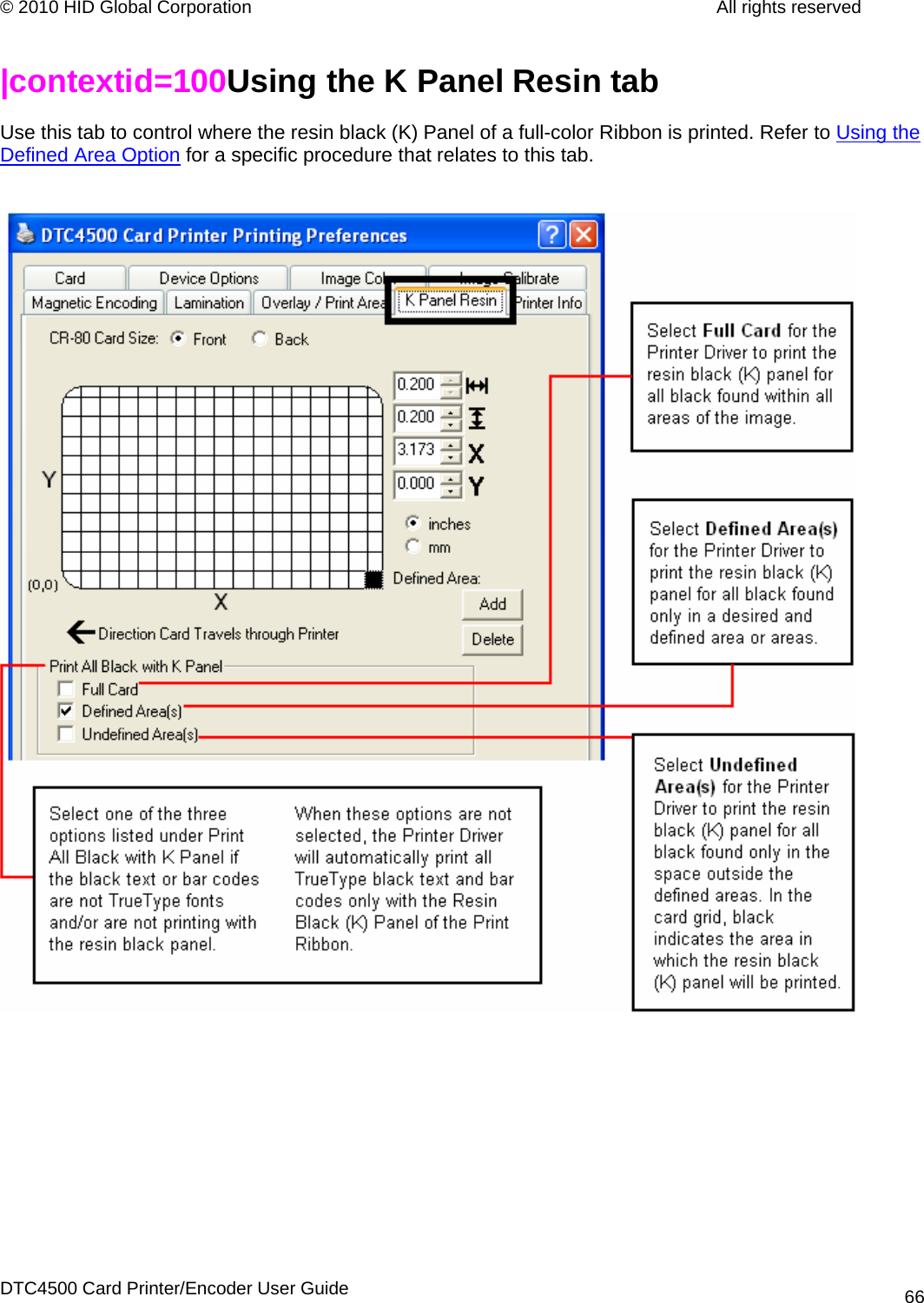
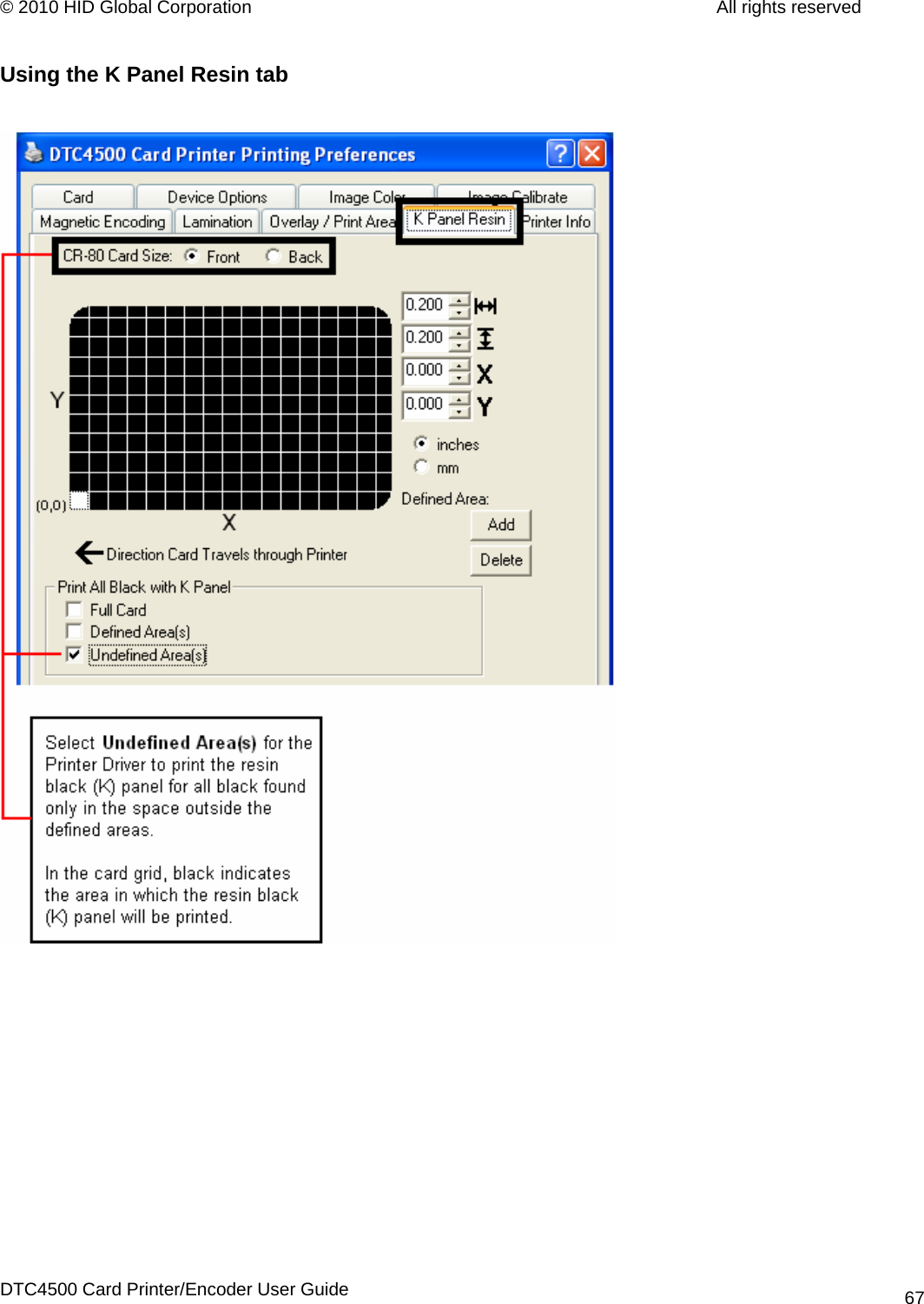
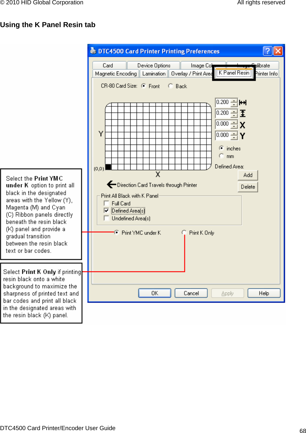
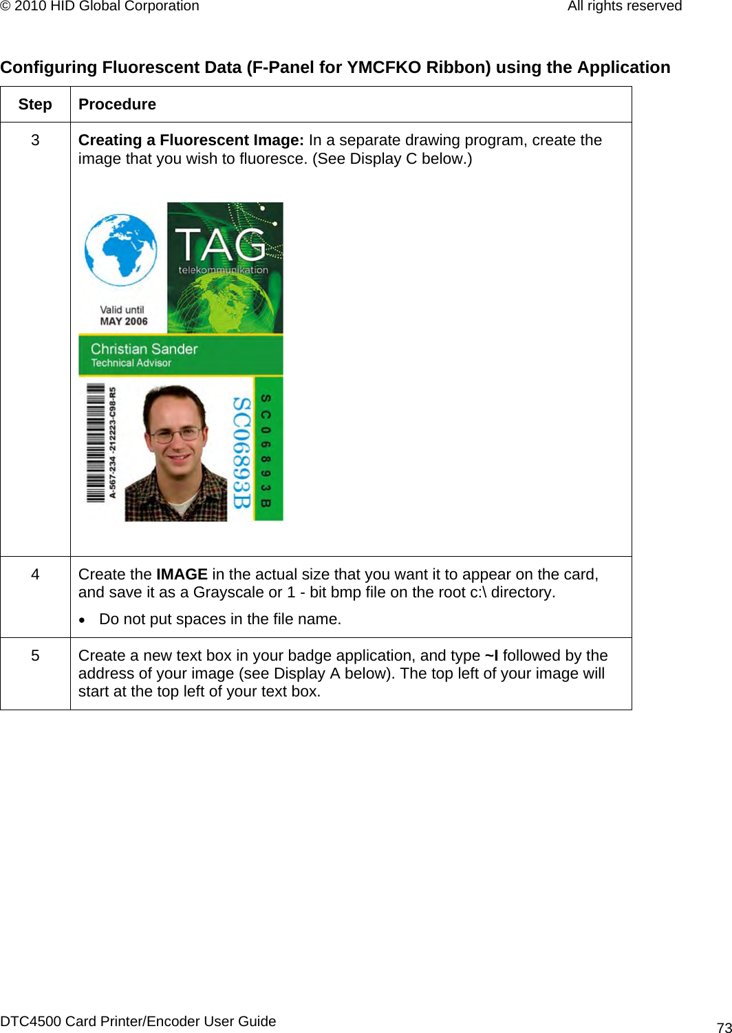
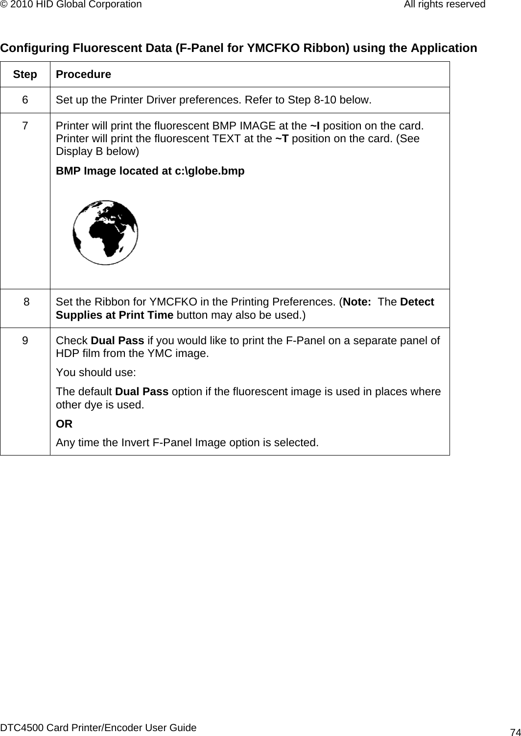
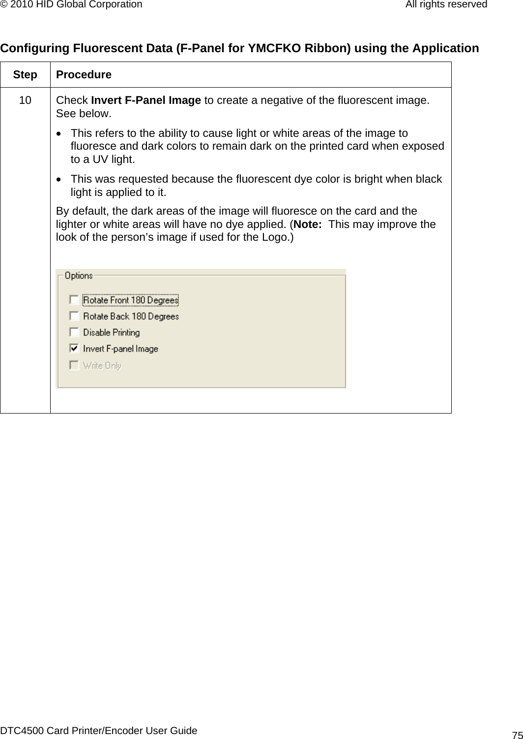
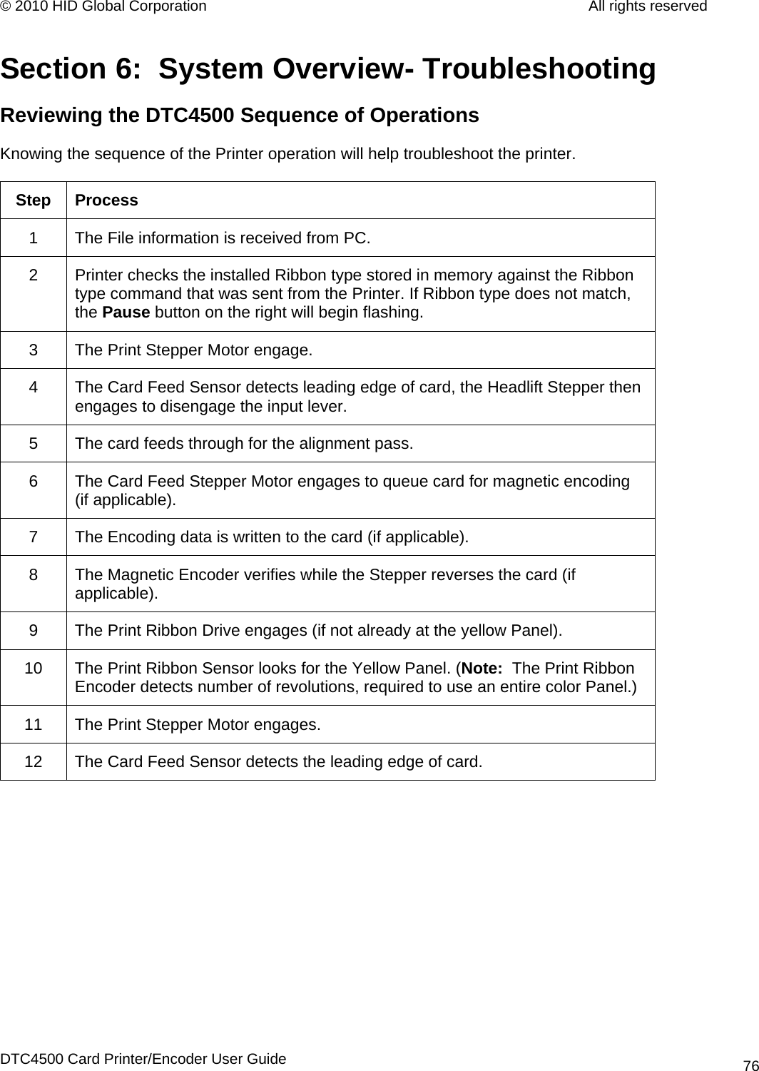
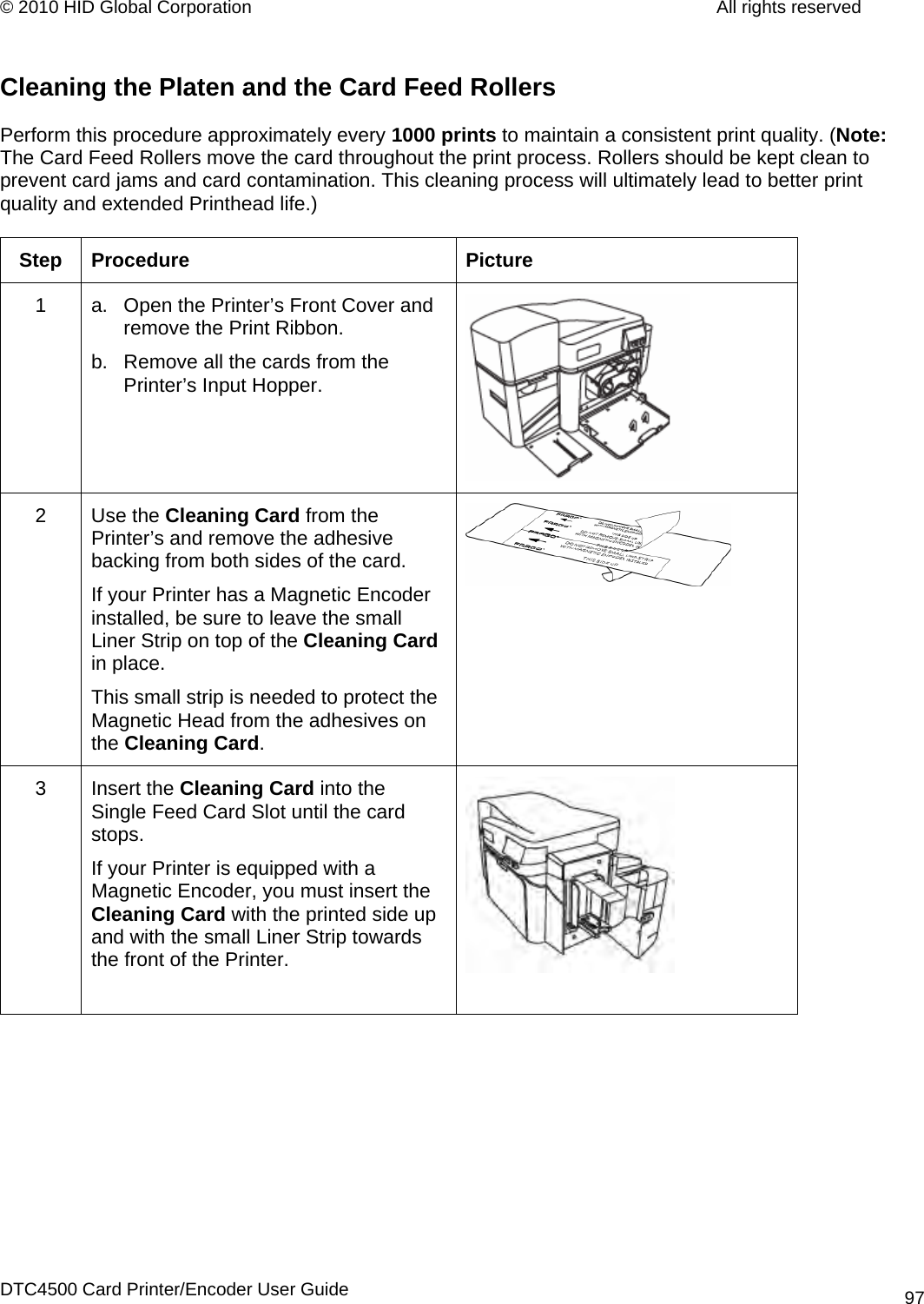
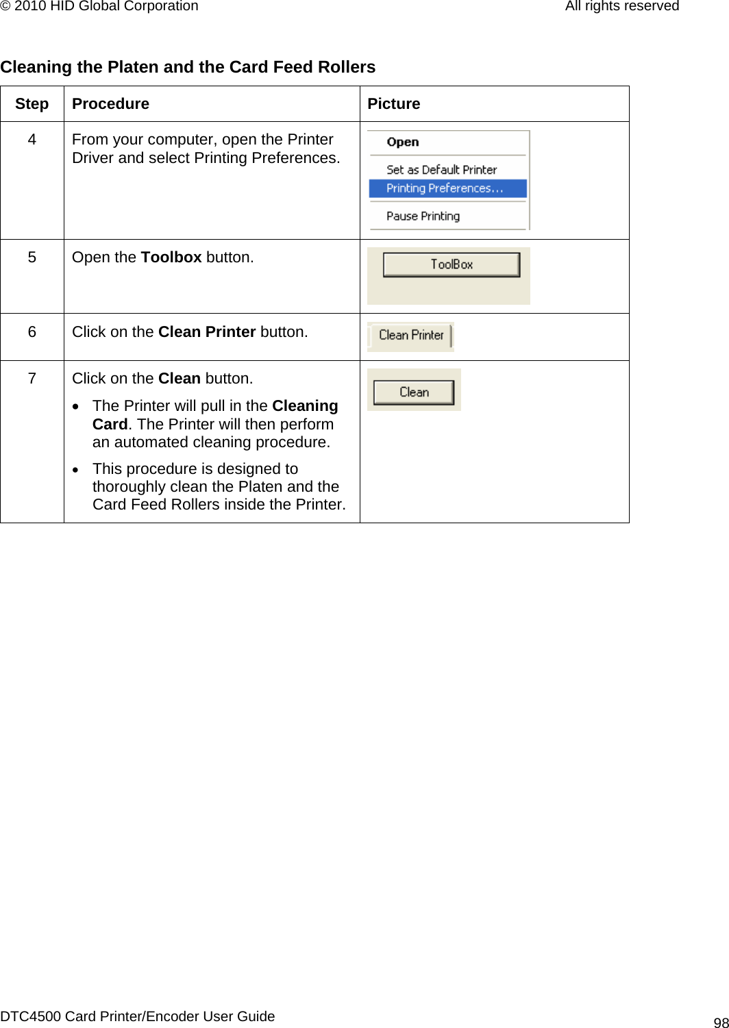
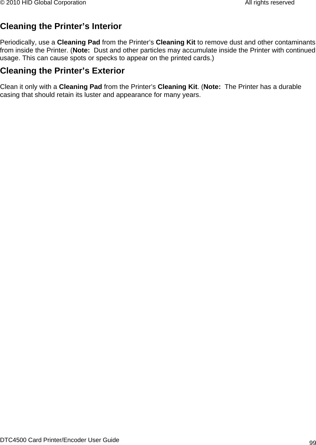
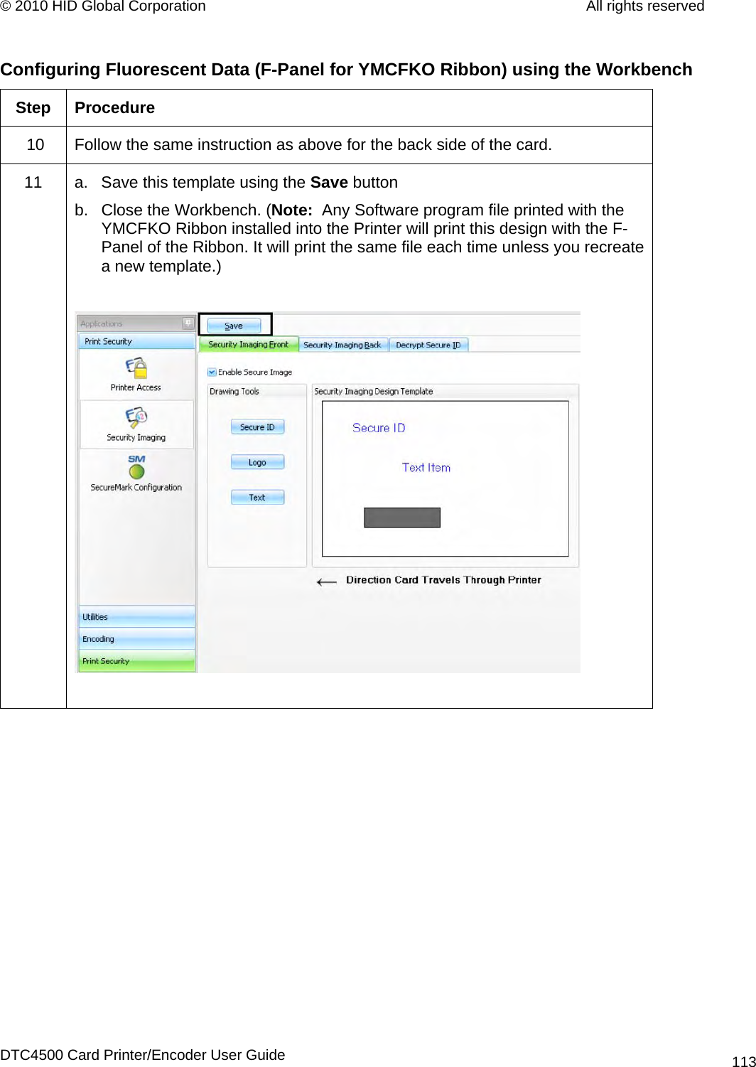
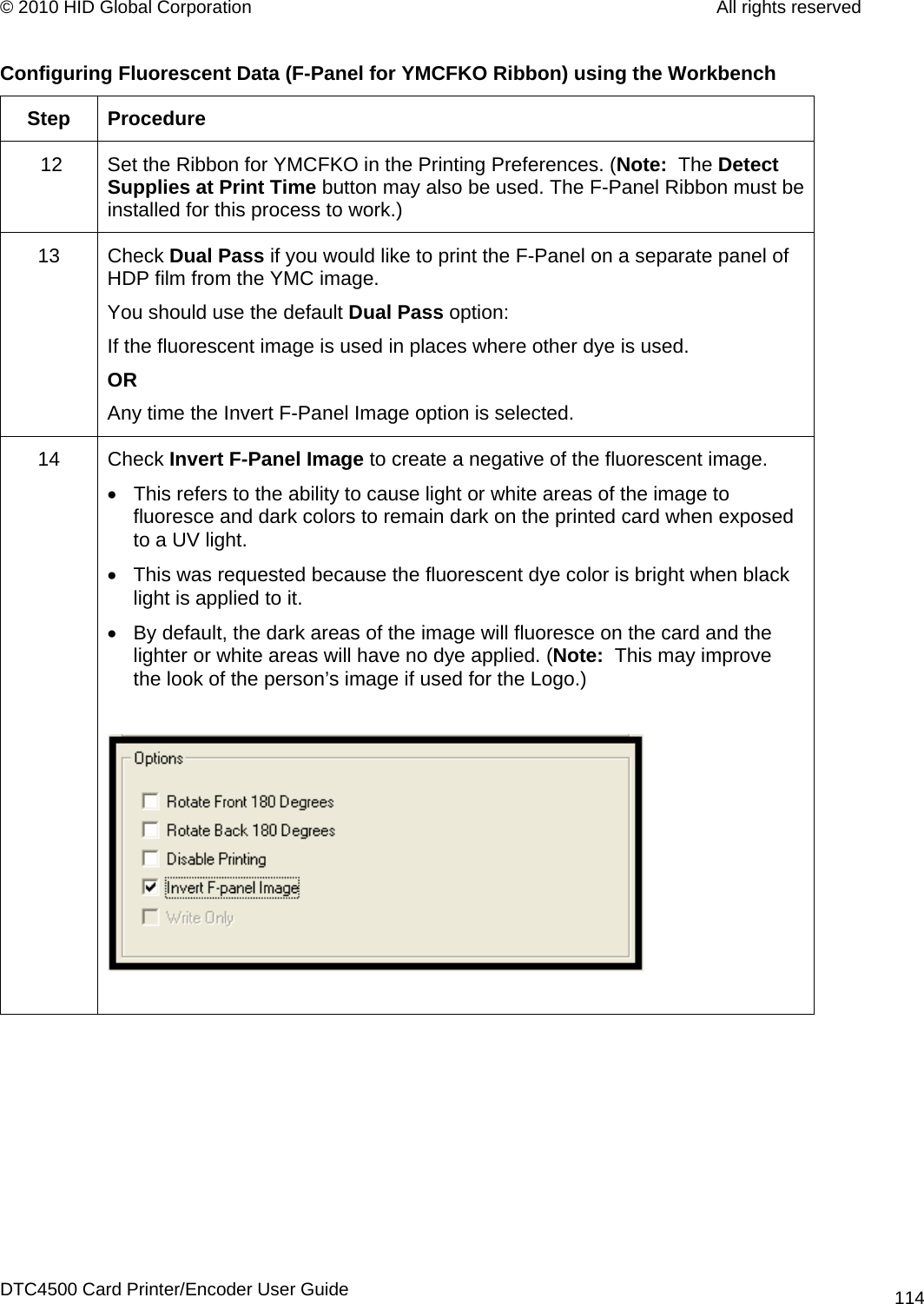
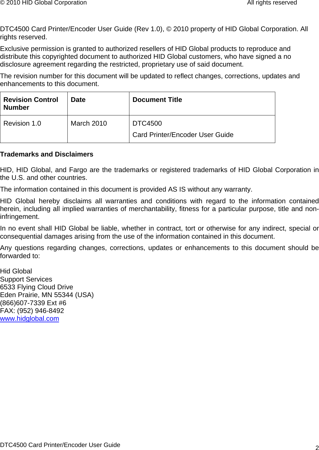
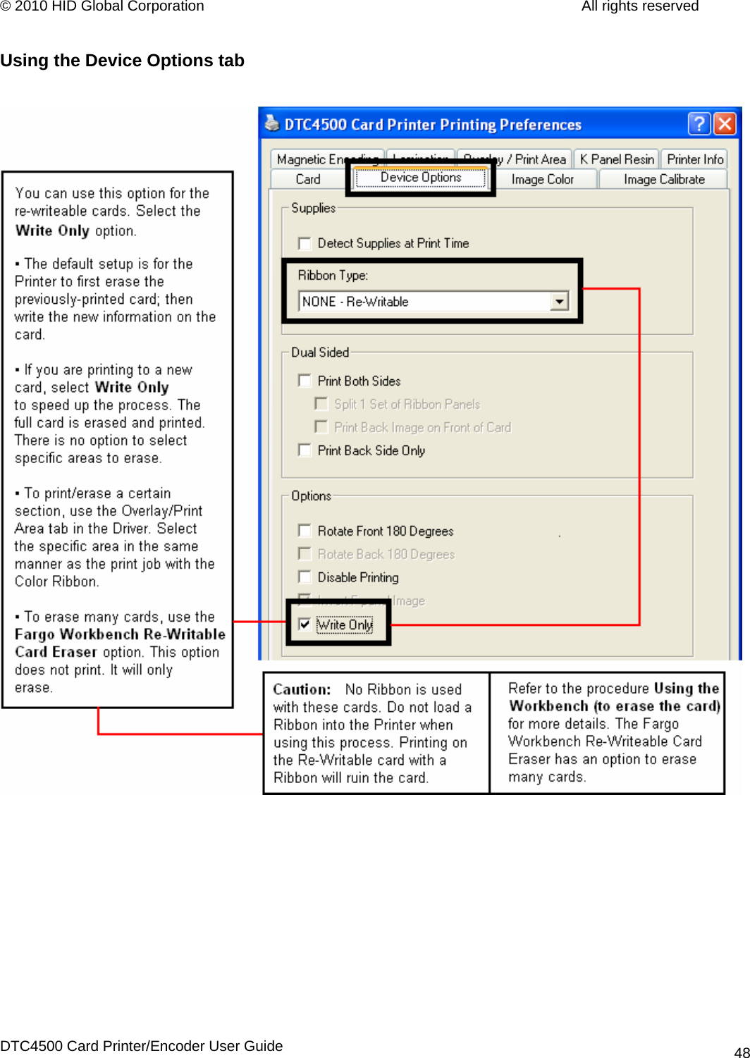
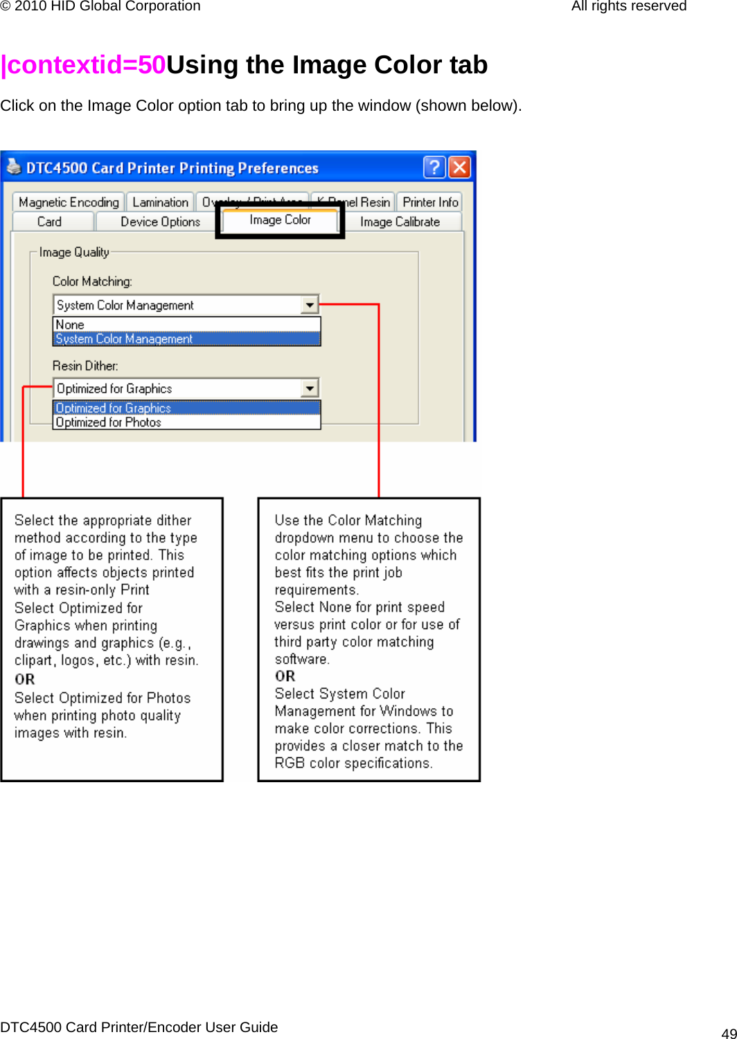
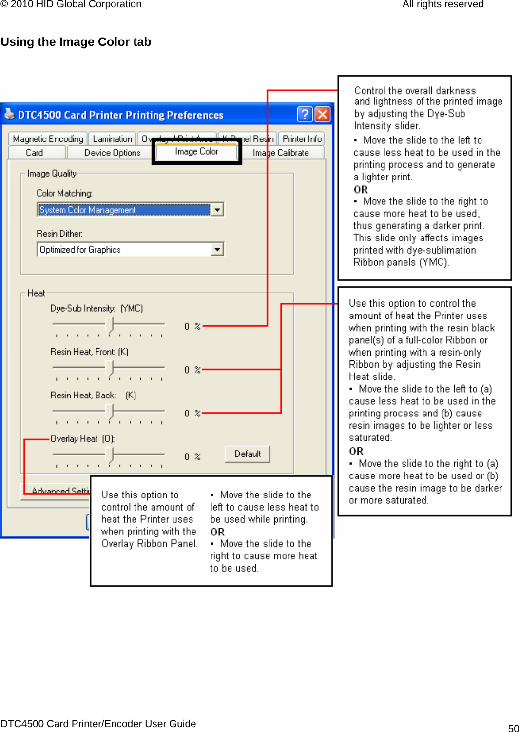
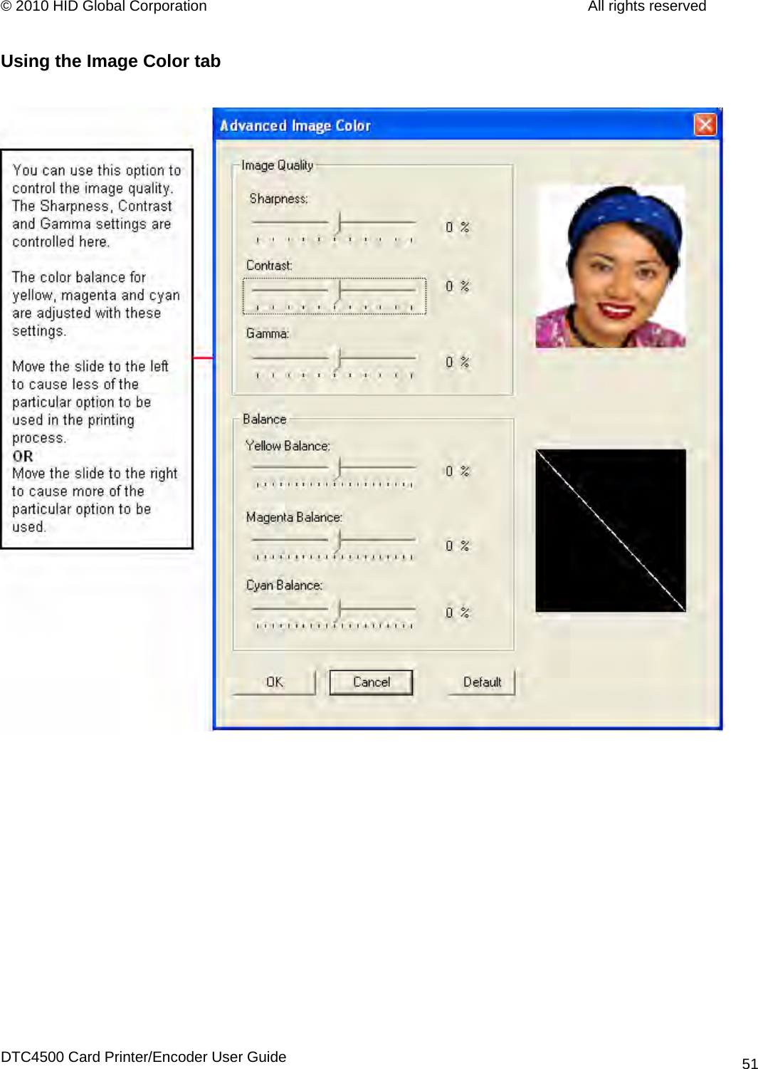
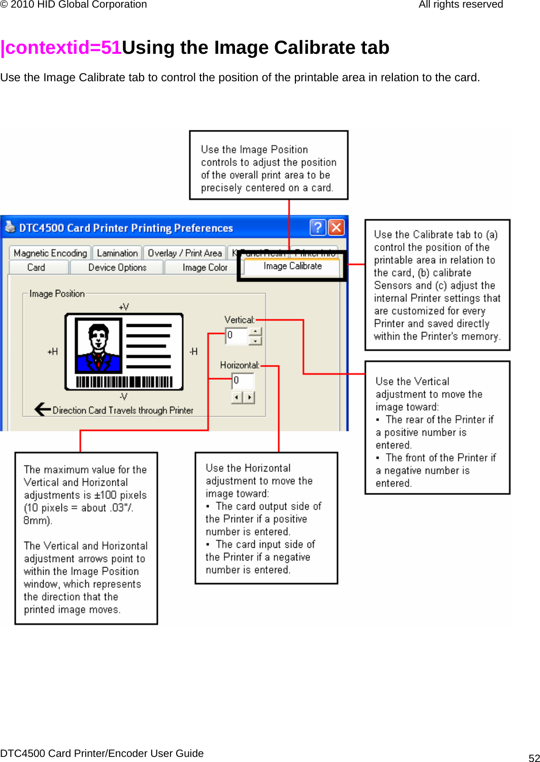
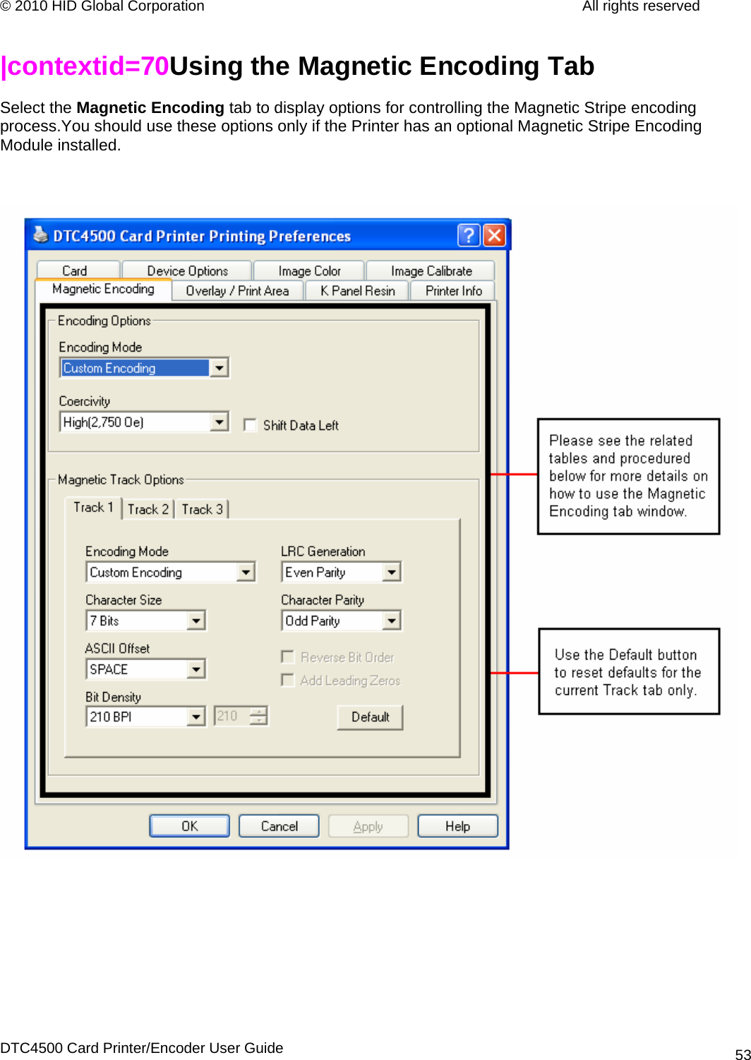
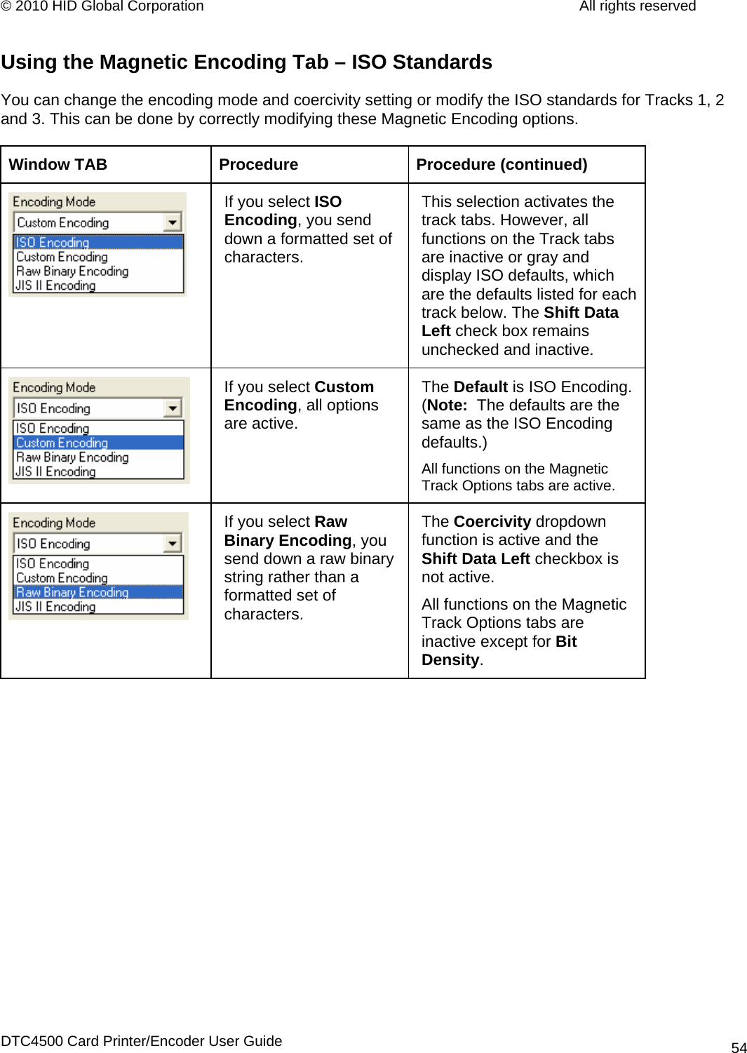
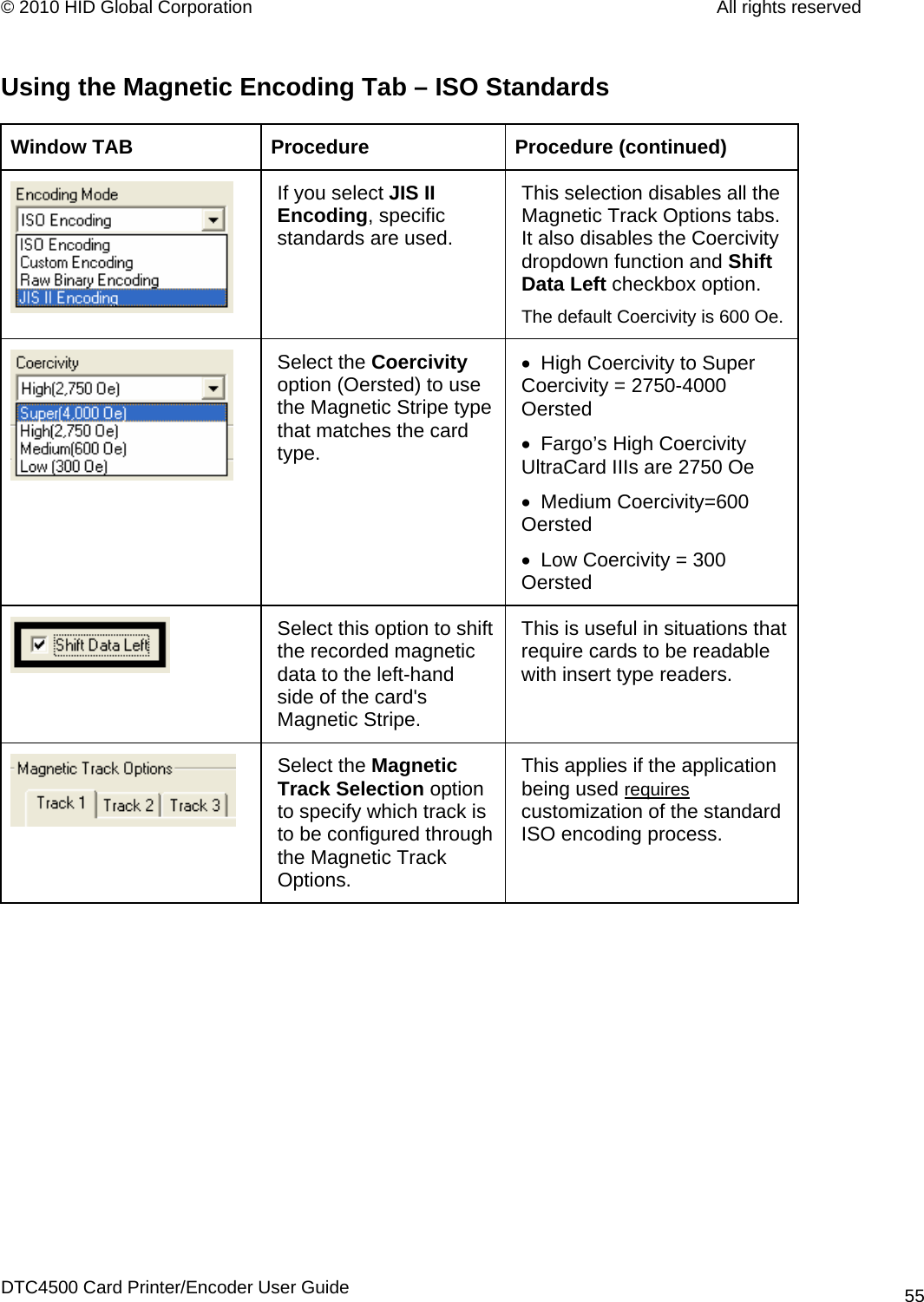
HID Global X001800C Card encoder RFID 13.56MHz Radio Module User Manual Using the Photo option
HID Global Corporation Card encoder RFID 13.56MHz Radio Module Using the Photo option
UserManual.wiki
>
HID Global
>
X001800C User Manual
user manual
Navigation menu
Upload a User Manual
Namespaces
Wiki Guide
HTML
PDF
Info
Views
User Manual
Discussion / Help
Navigation

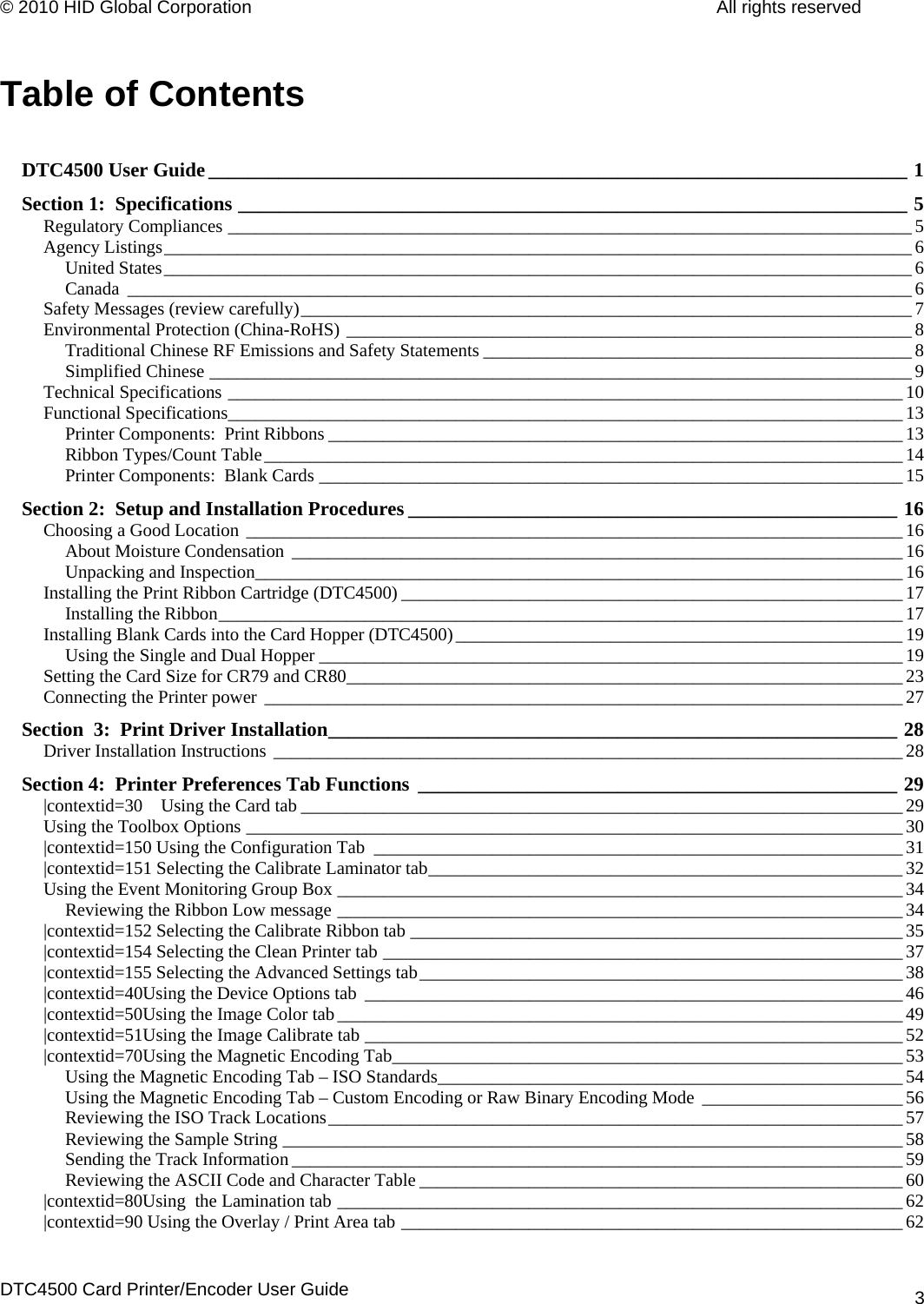
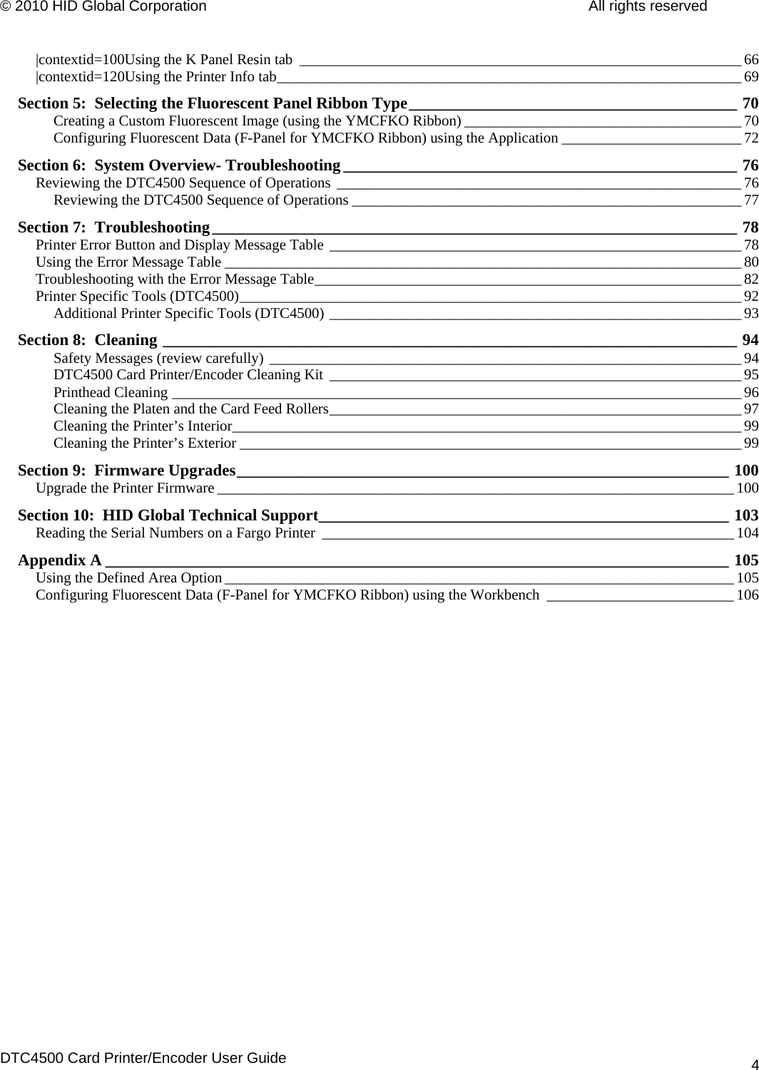
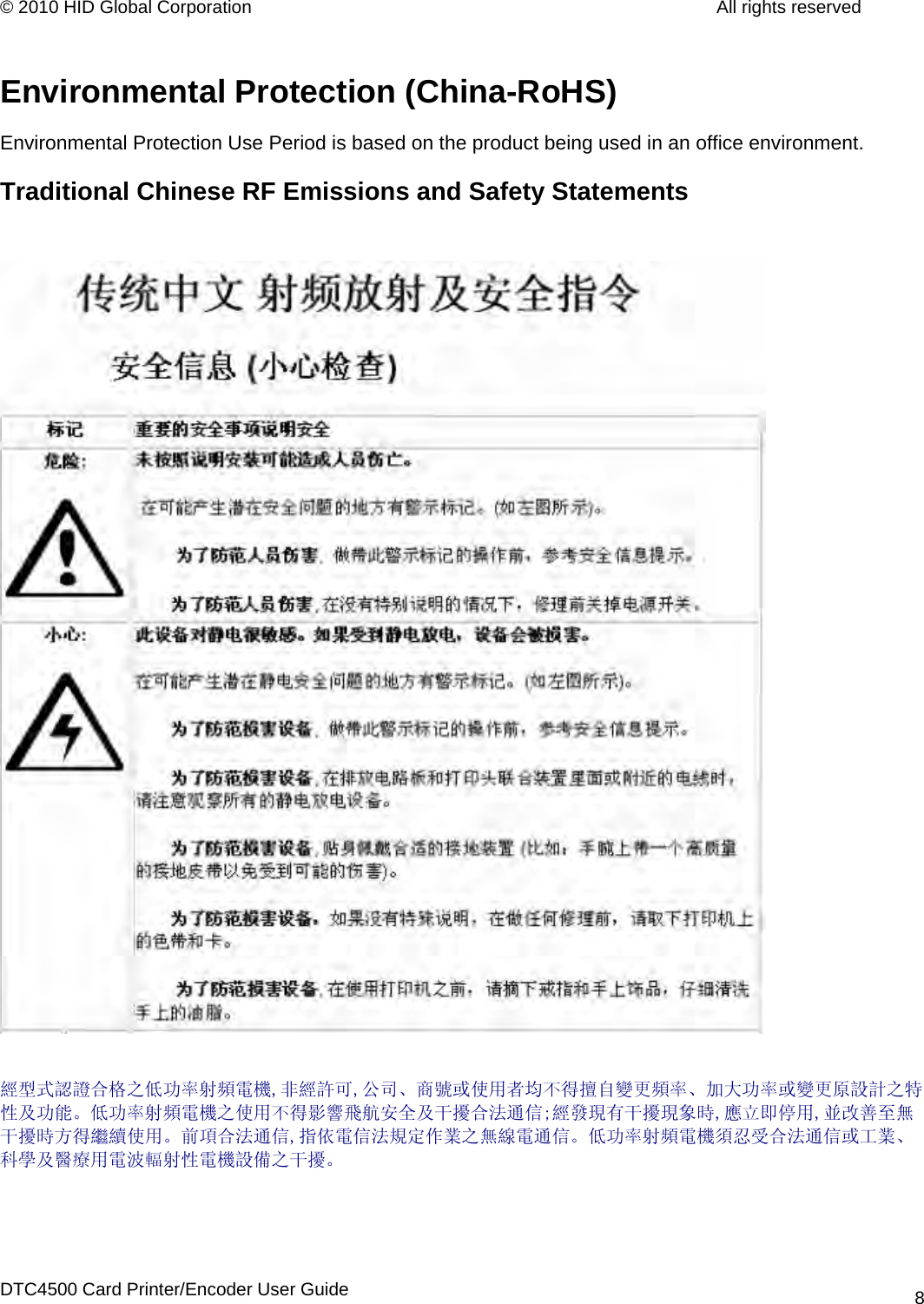
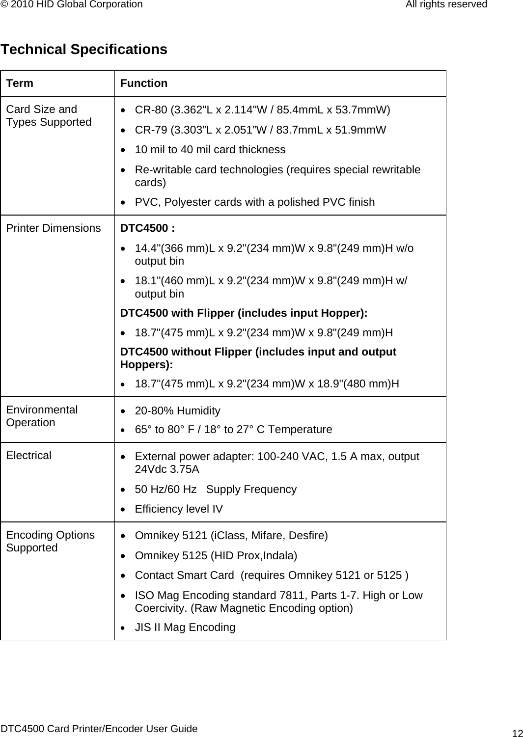
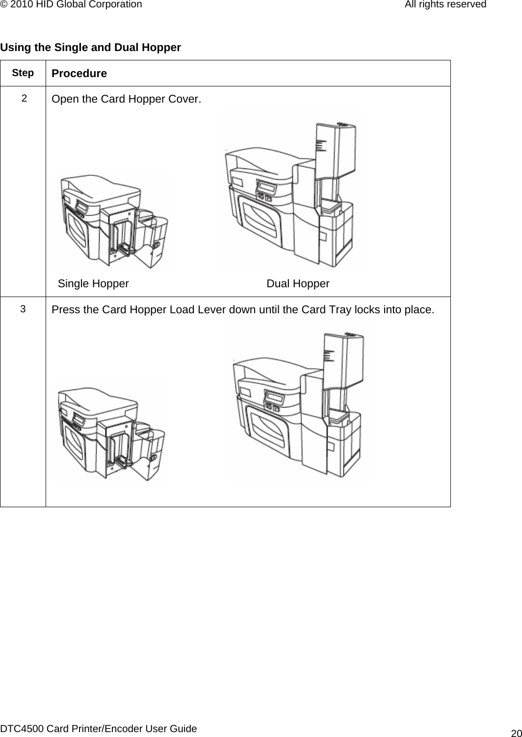
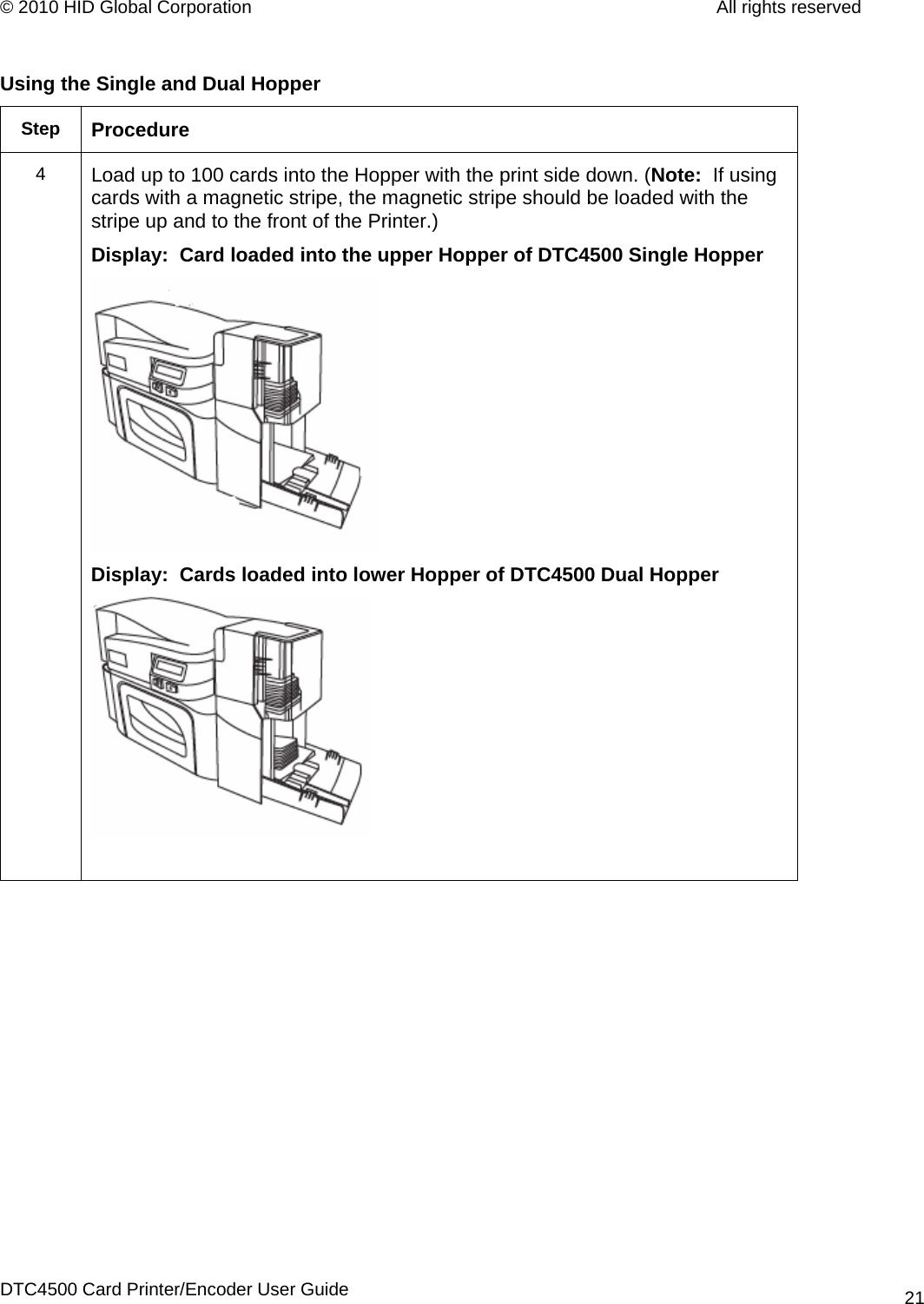
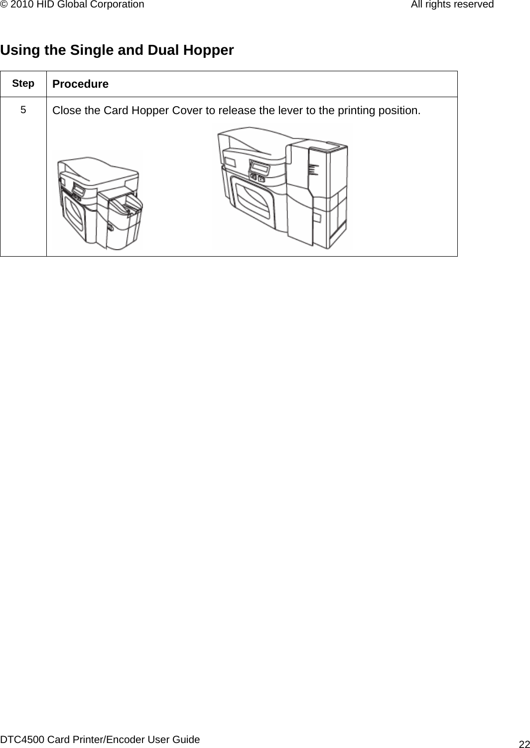
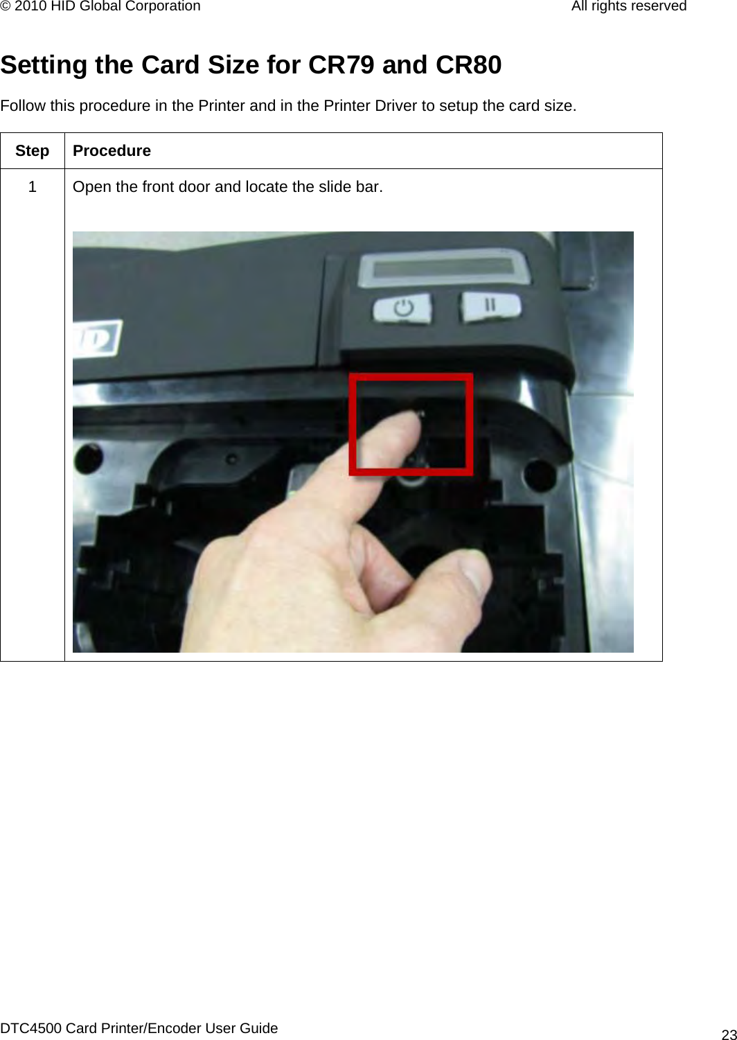
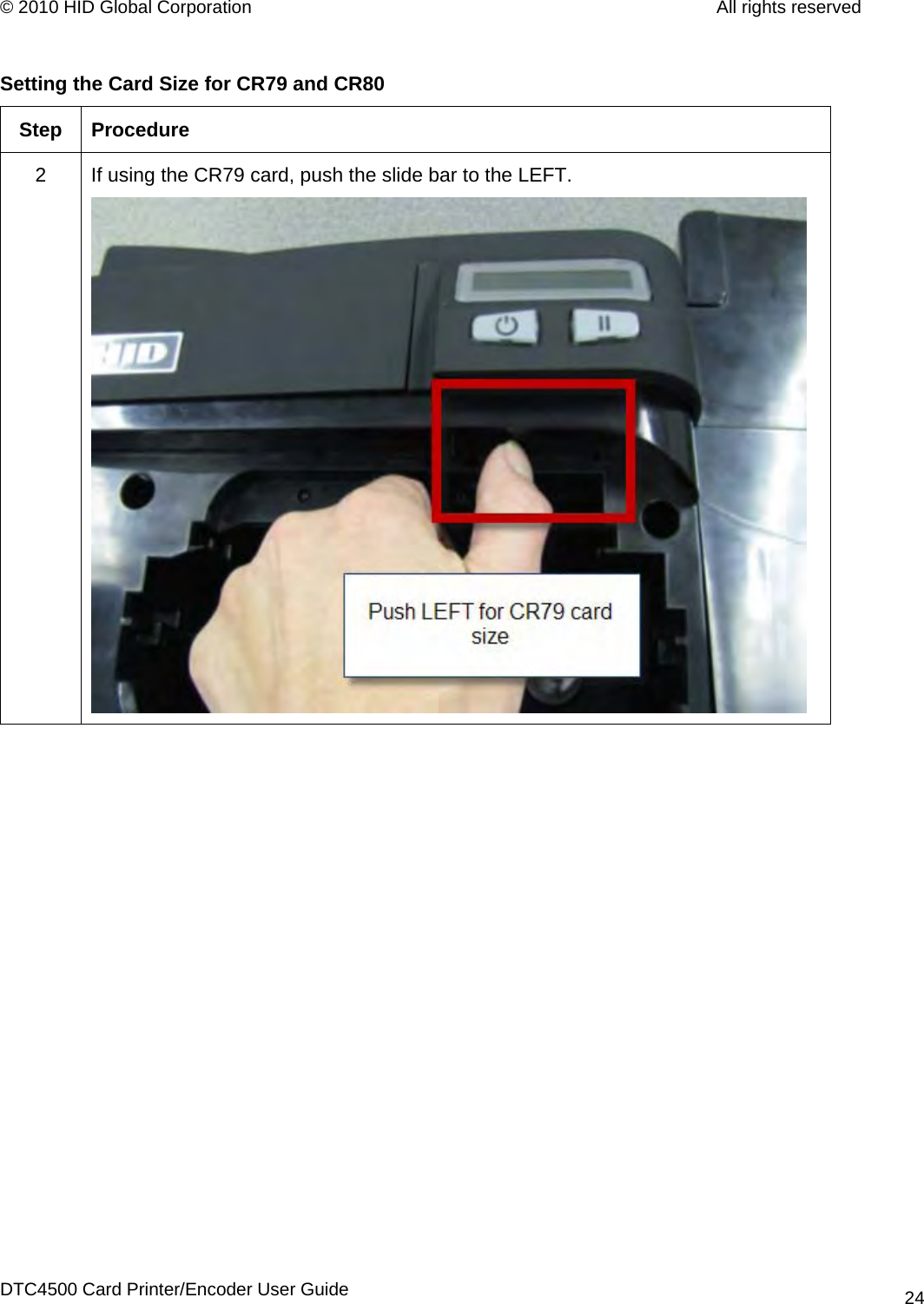
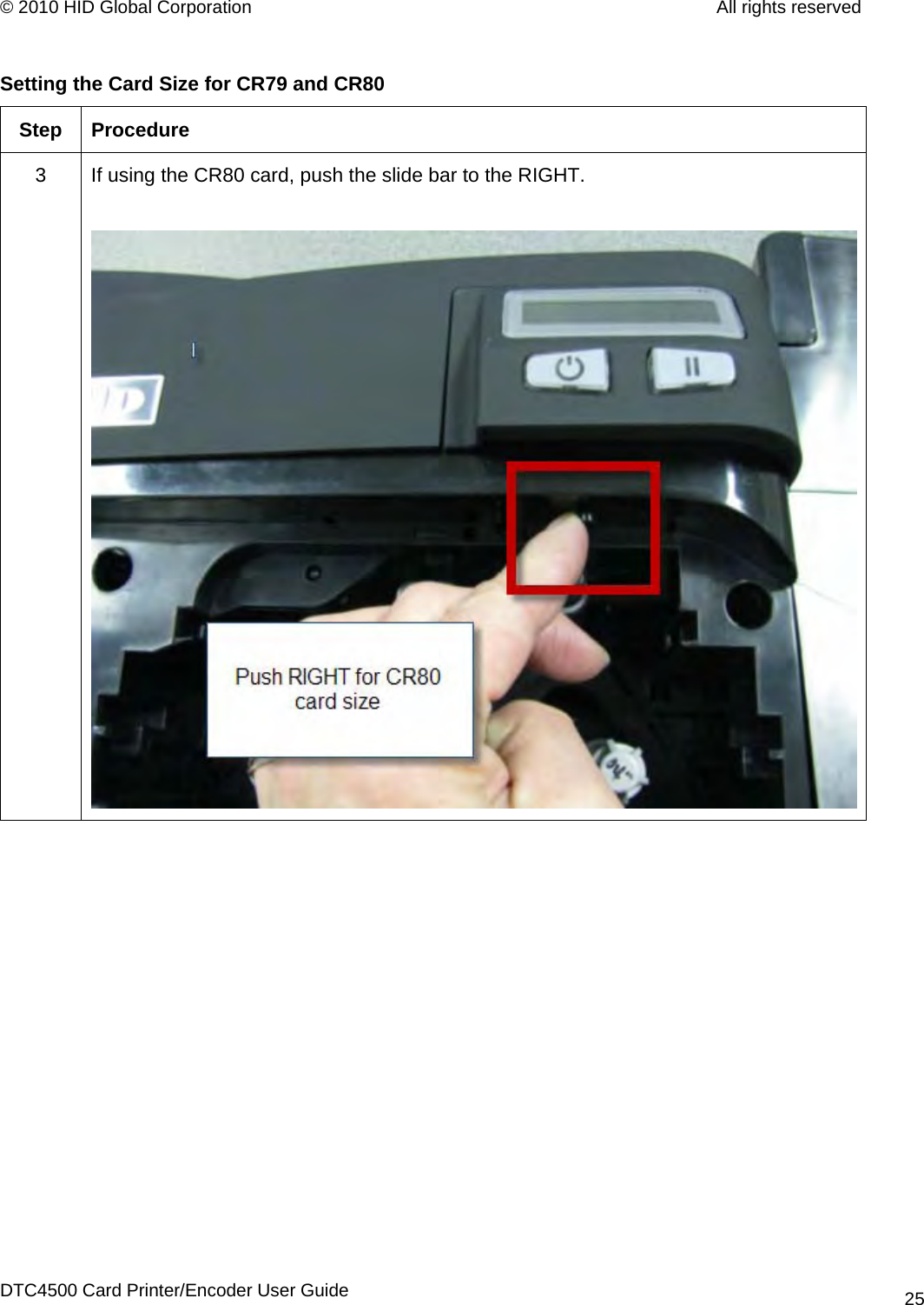
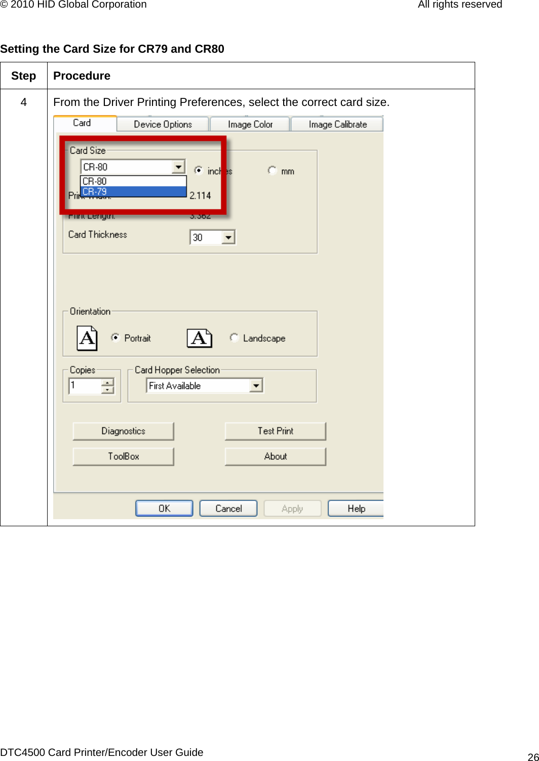
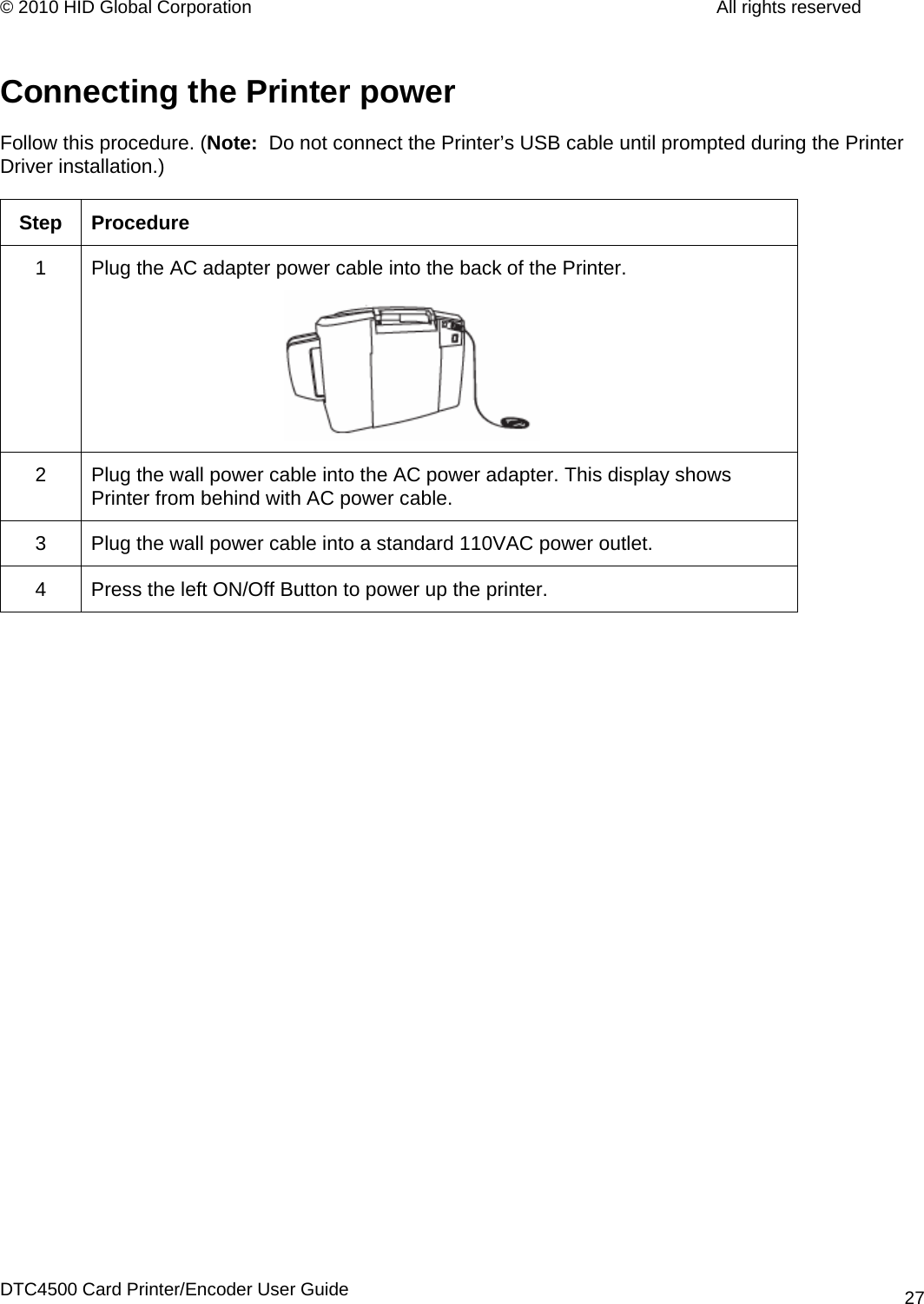
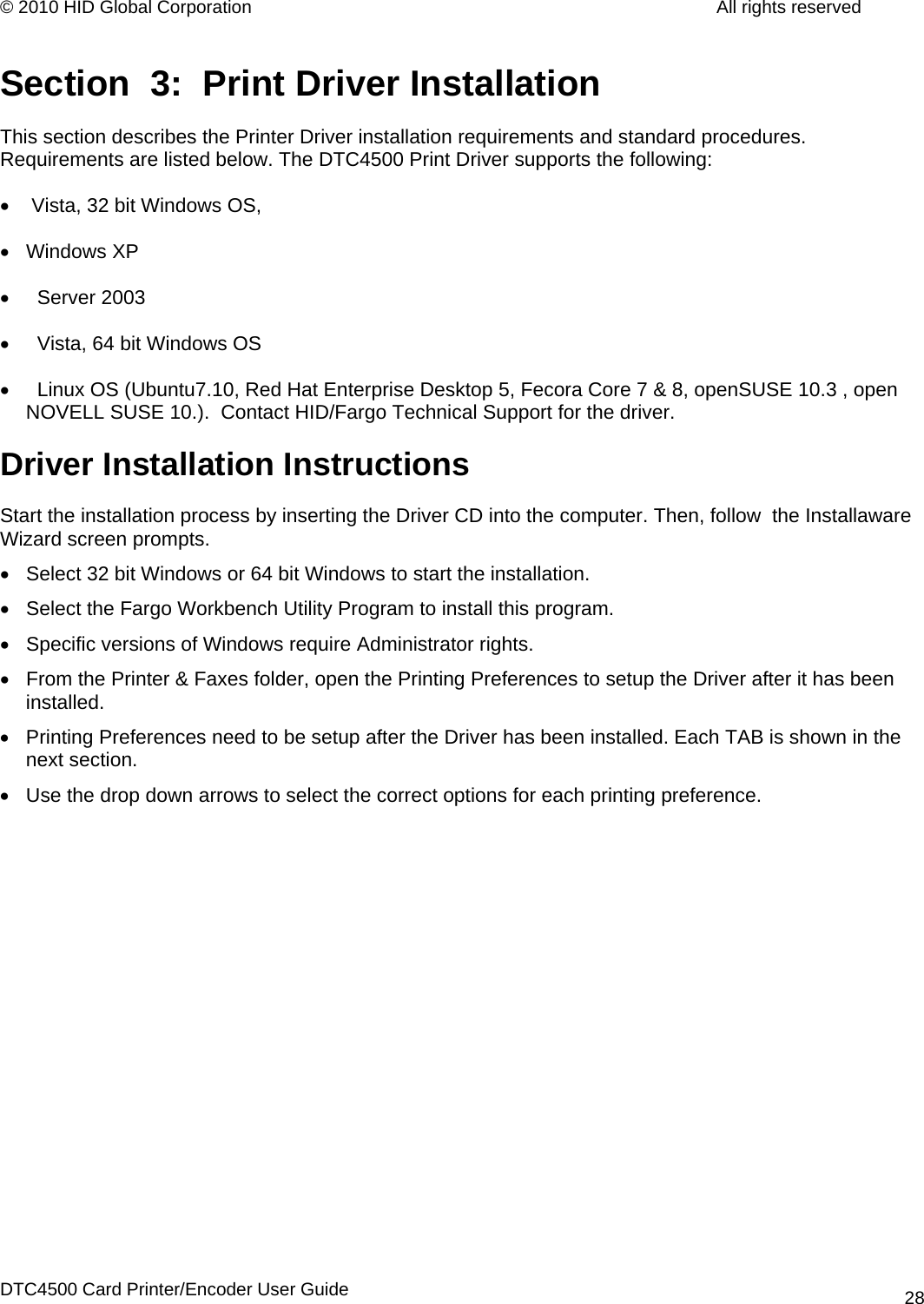
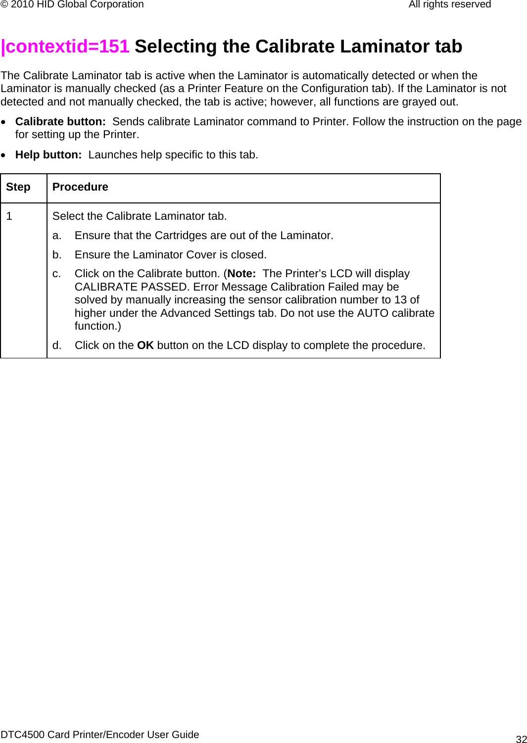
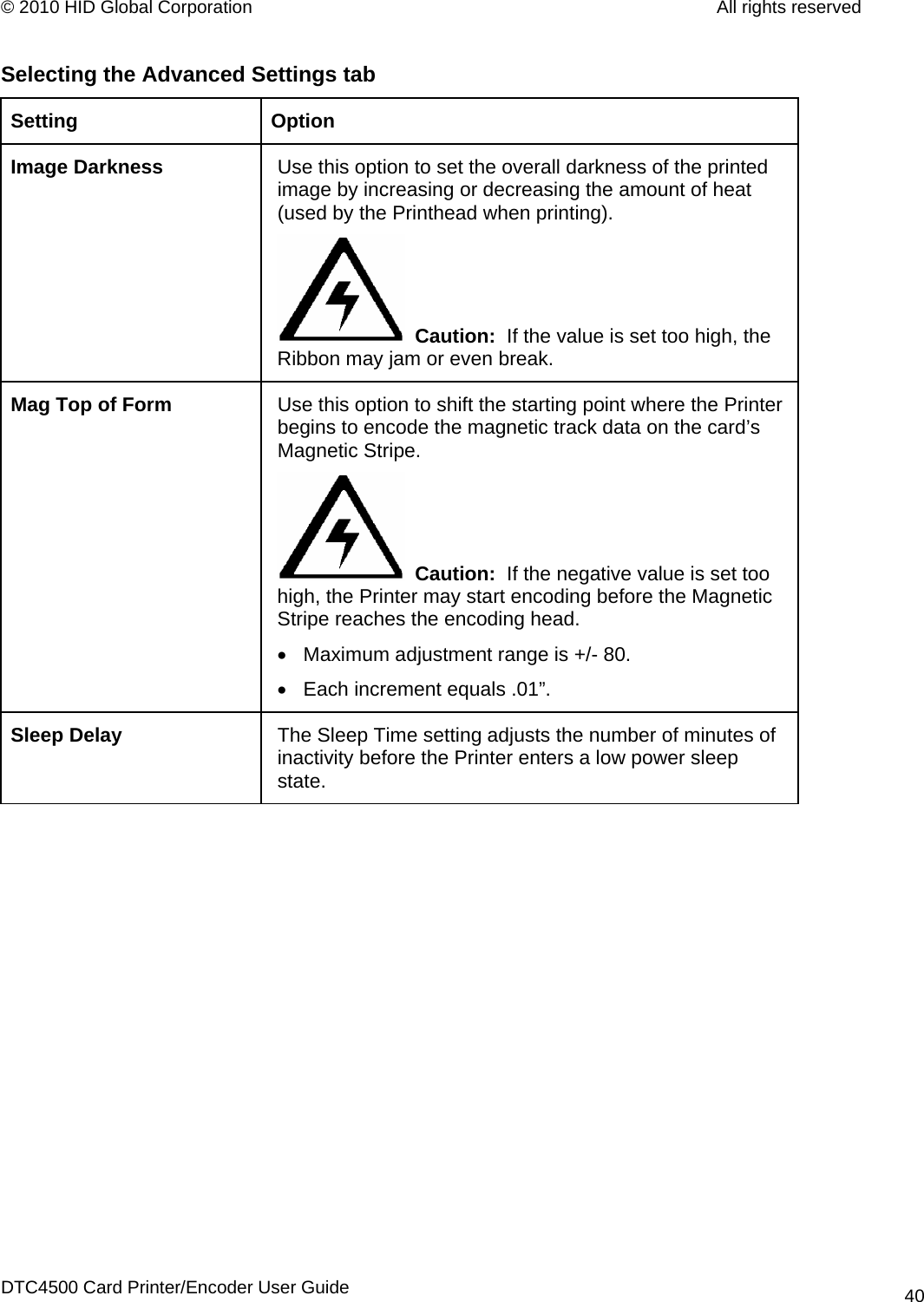
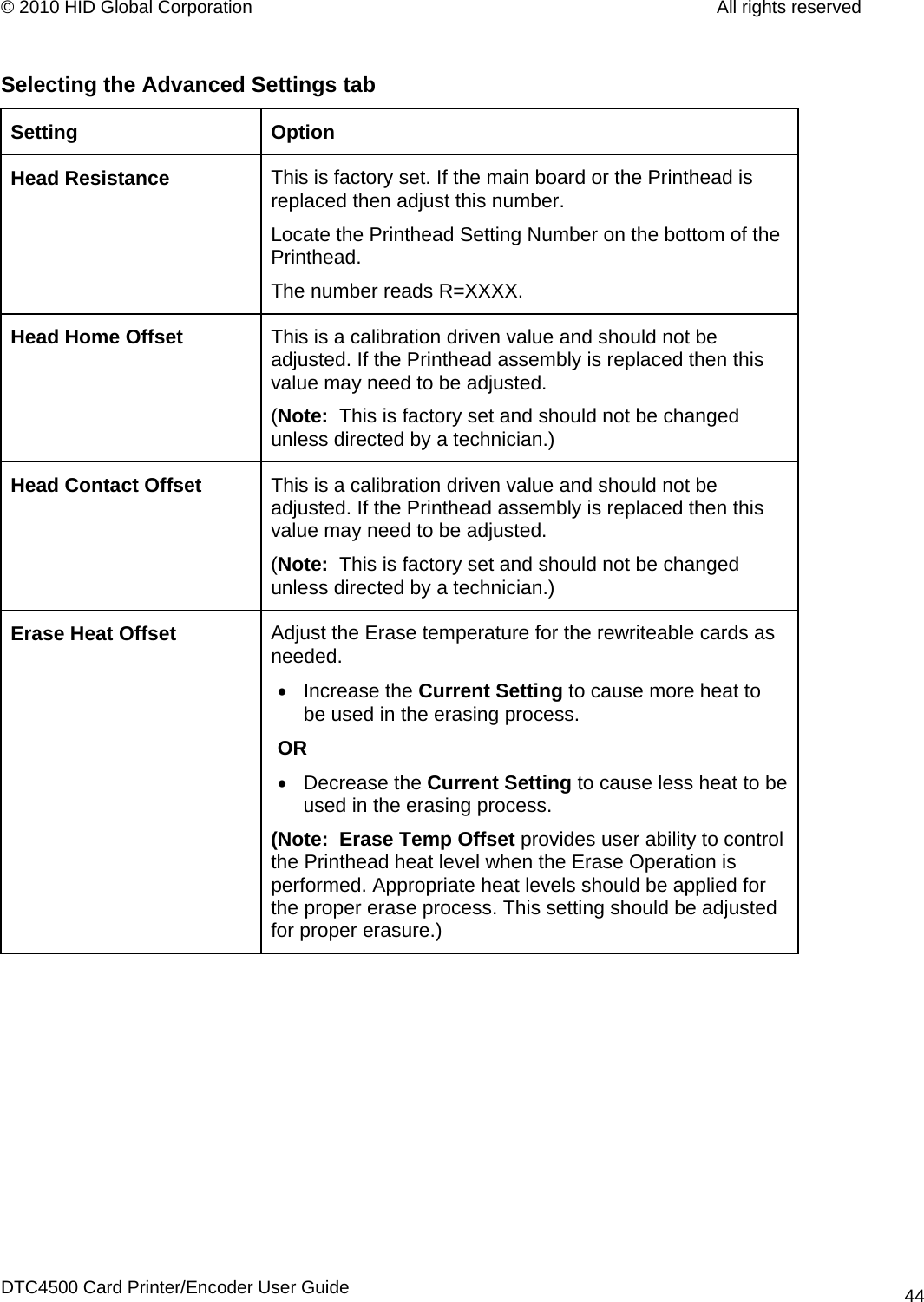
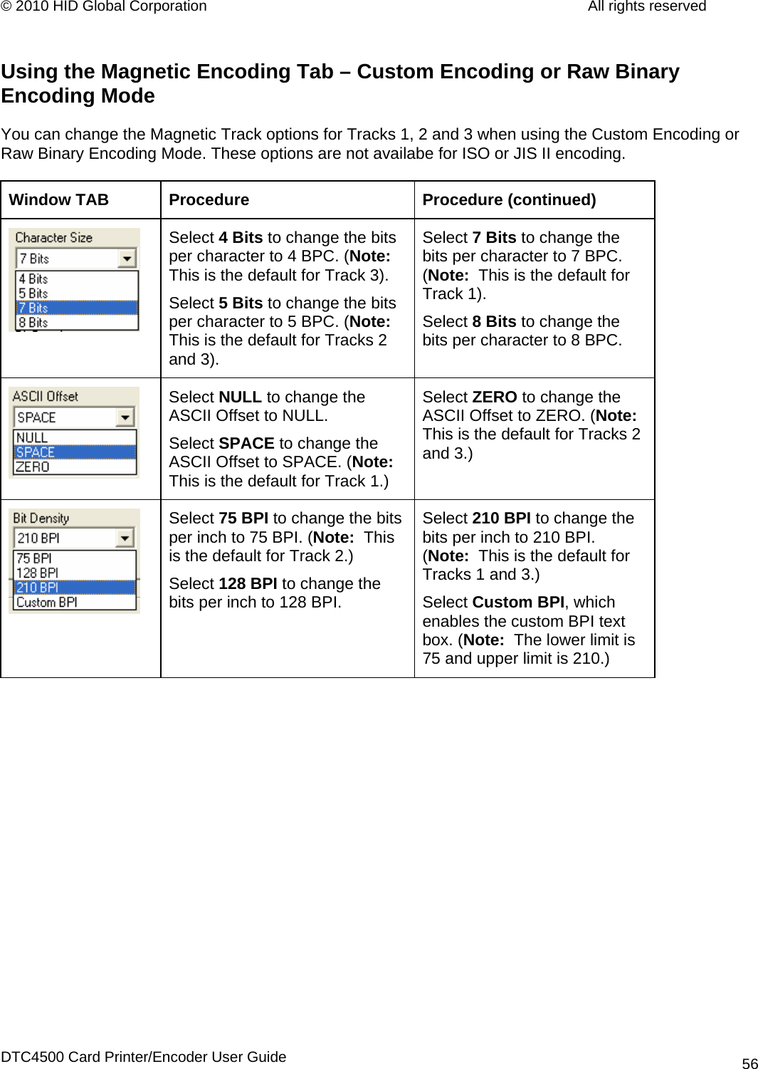
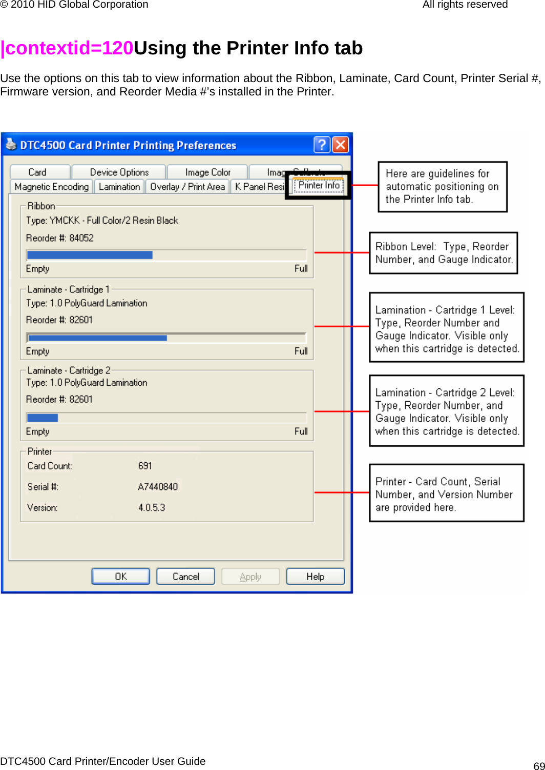
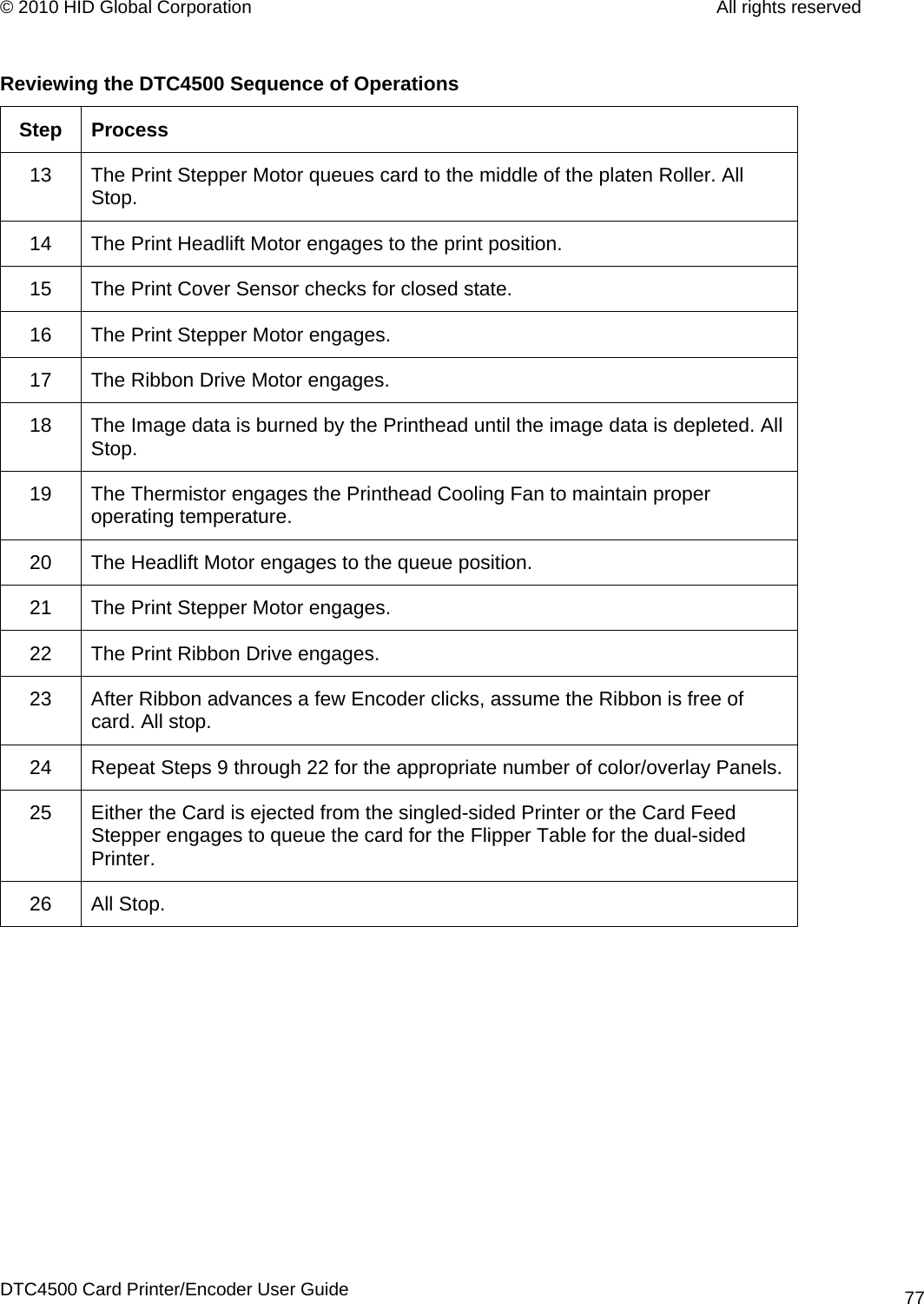
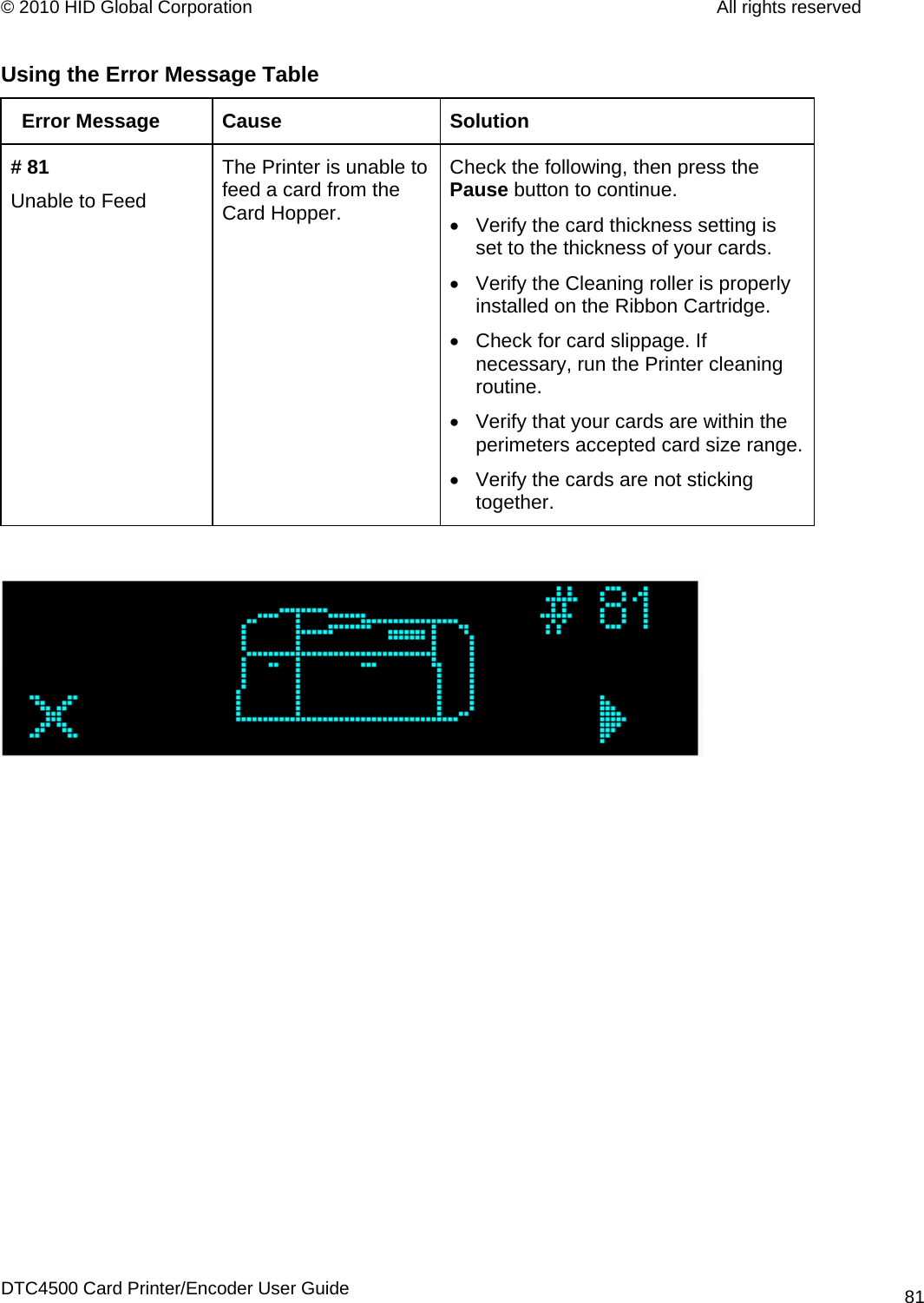
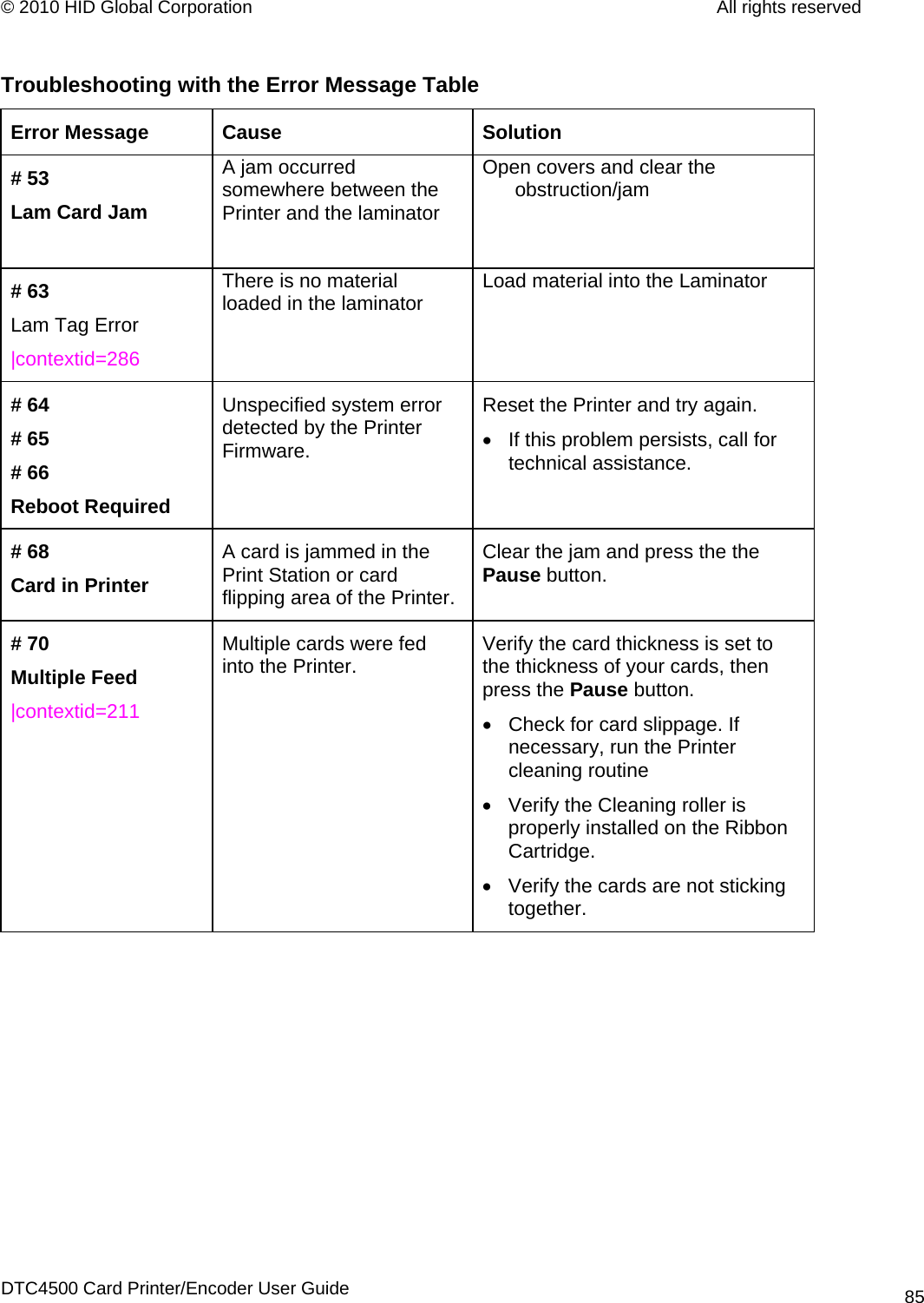
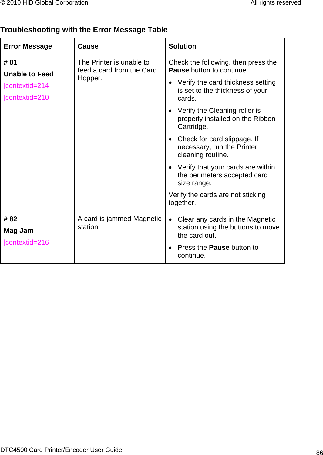
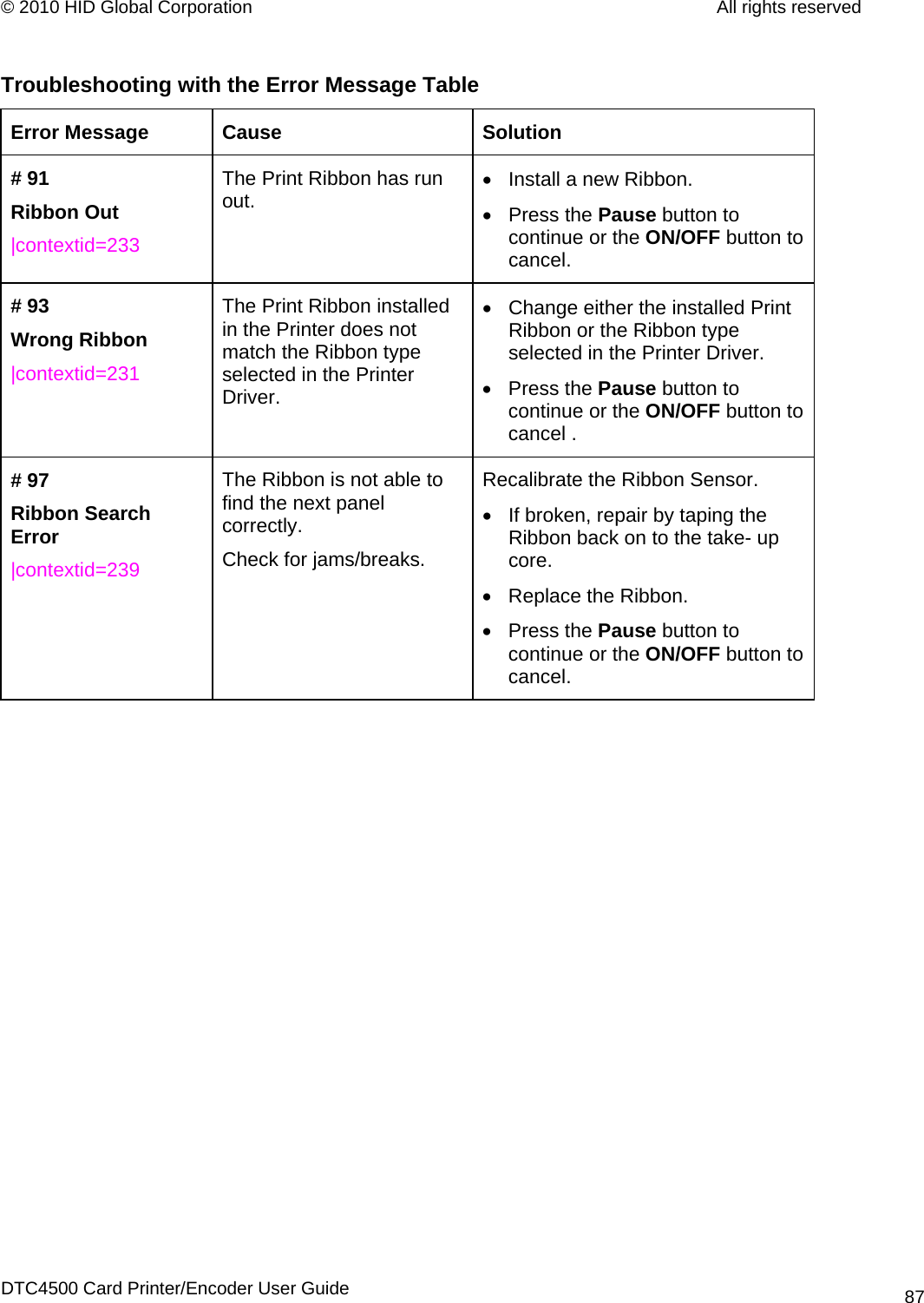
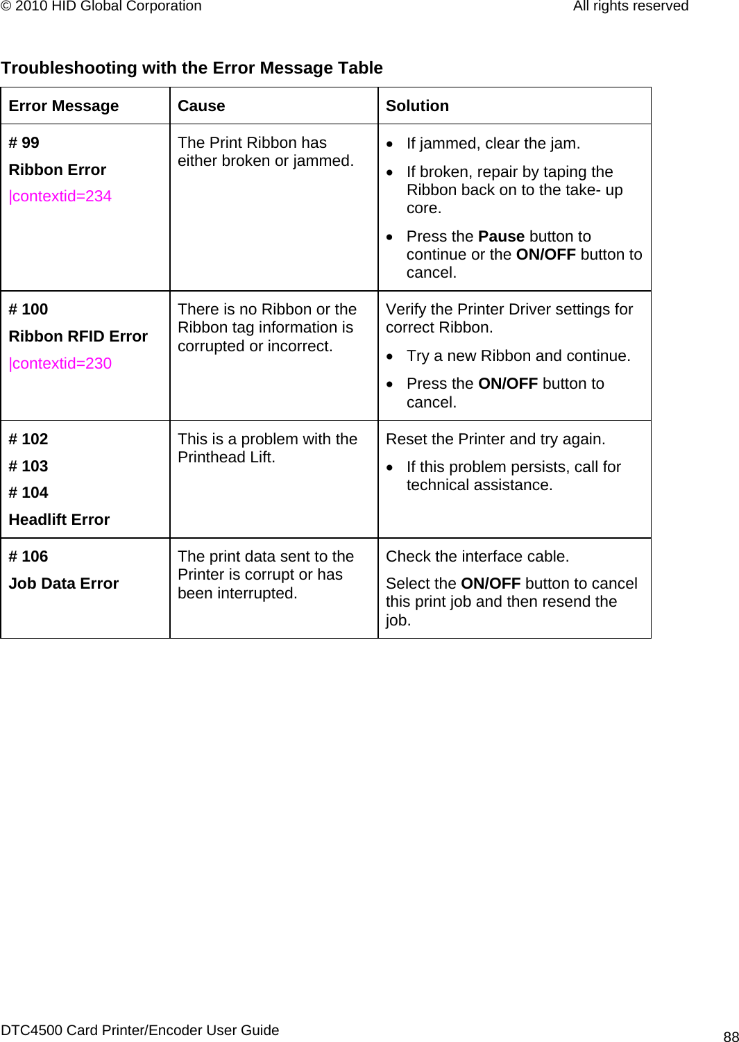
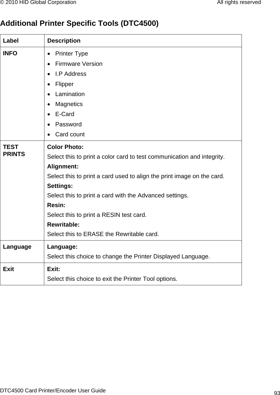
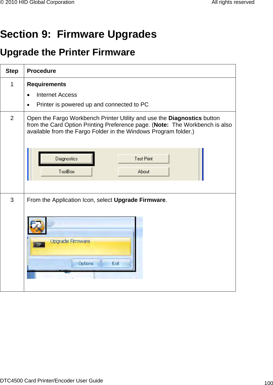
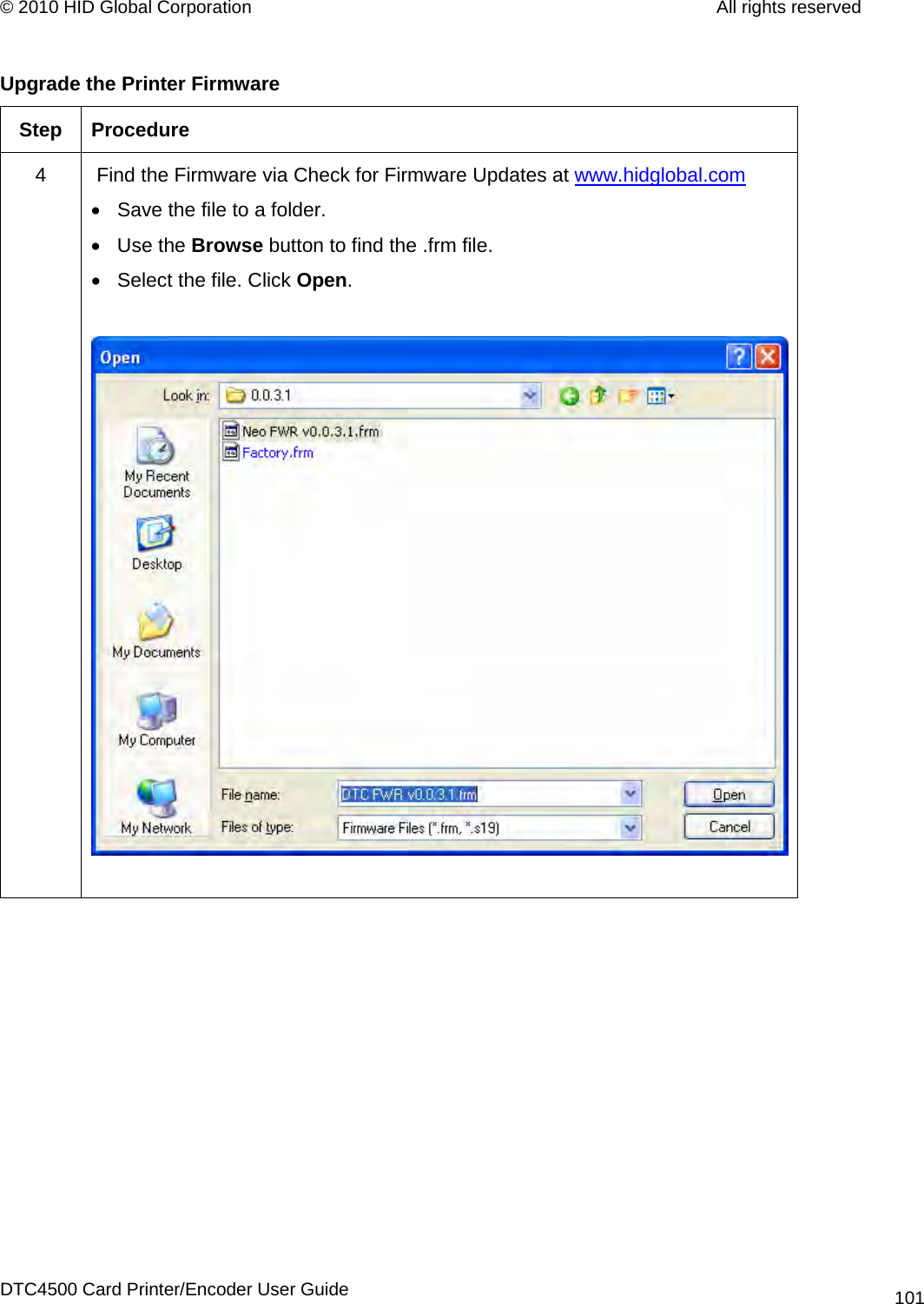
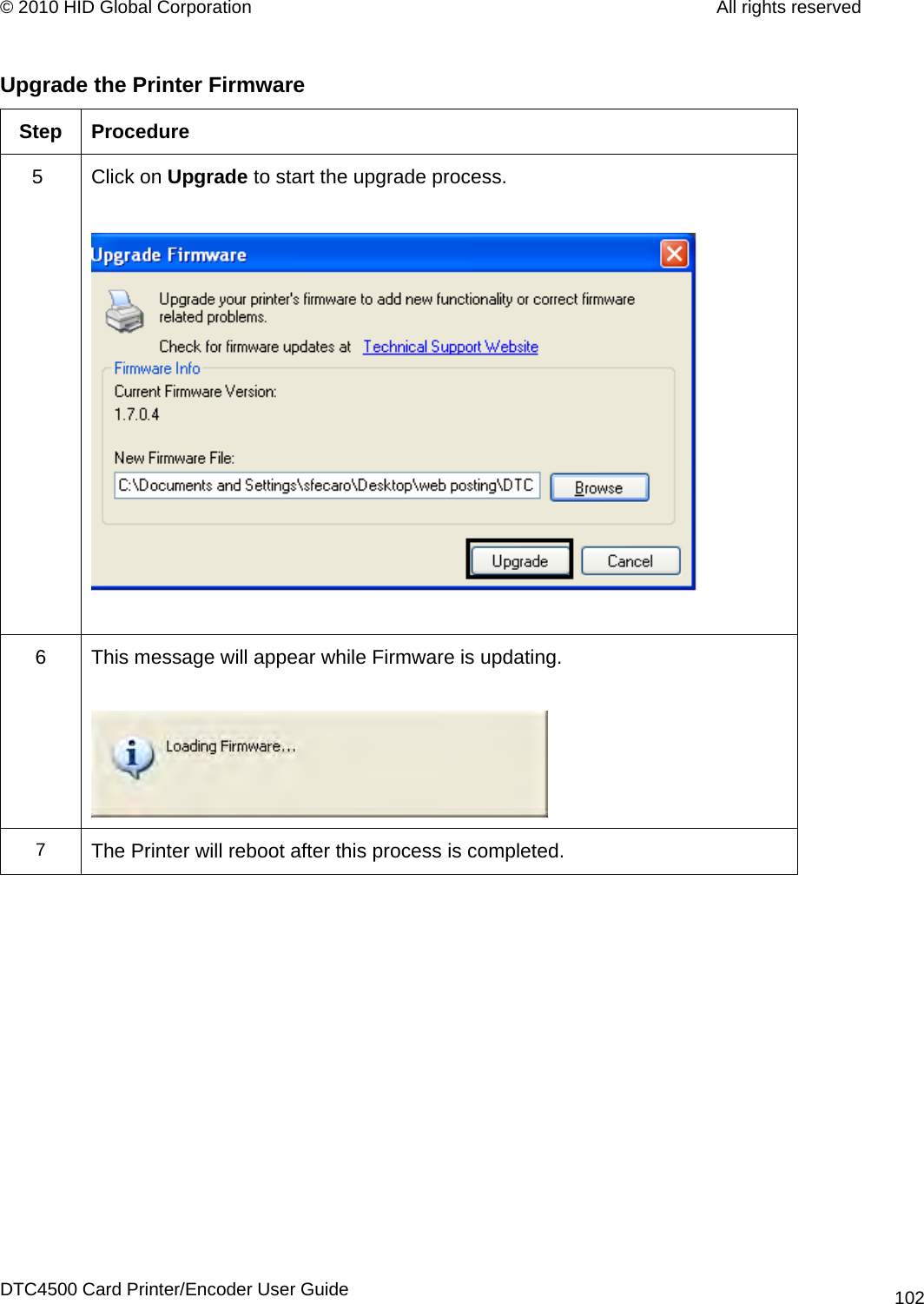
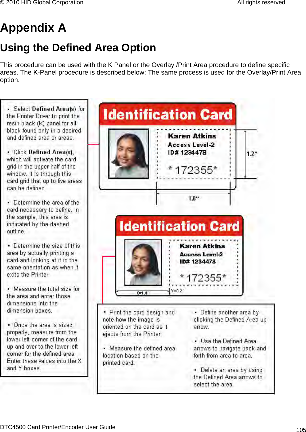
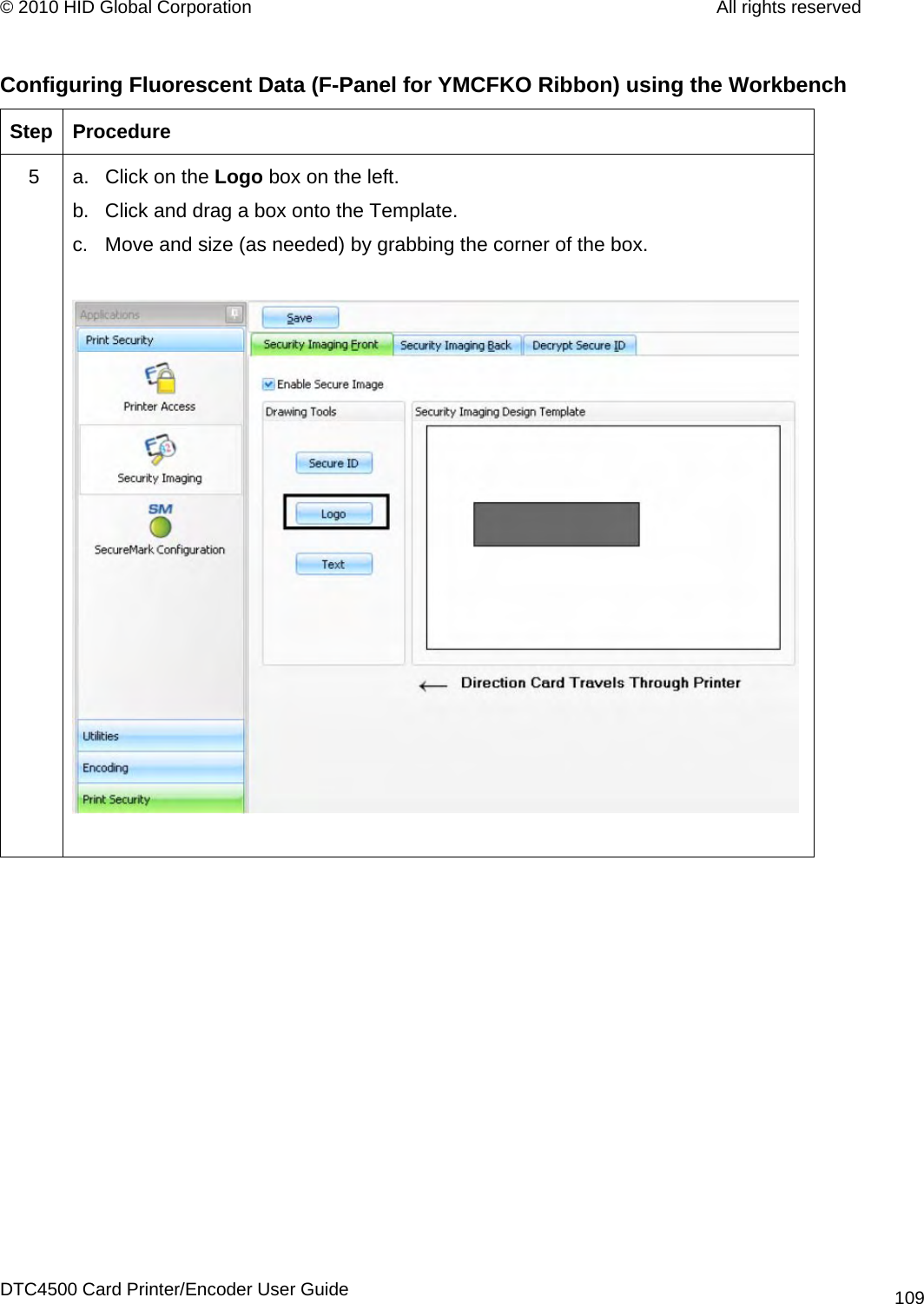
![© 2010 HID Global Corporation All rights reserved Reviewing the ASCII Code and Character Table ASCII Code Character ASCII Code Character ASCII Code Character 32 space 56 8 80 P 33 ! 57 9 81 Q 34 58 : 82 R 35 # 59 ; 83 S 36 $ 60 < 84 T 37 % 61 = 85 U 38 and 62 > 86 V 39 ' 63 ? 87 W 40 ( 64 @ 88 X 41 ) 65 A 89 Y 42 * 66 B 90 Z 43 + 67 C 91 [ 44 ' 68 D 92 \ 45 - 69 E 93 ] DTC4500 Card Printer/Encoder User Guide 60](https://usermanual.wiki/HID-Global/X001800C/User-Guide-1266241-Page-60.png)