HID Global X002100 Color Card Printer User Manual PLT 02496 DTC5500LMX User Guide
HID Global Corporation Color Card Printer PLT 02496 DTC5500LMX User Guide
UserManual.wiki
>
HID Global
>
X002100 User Manual
User Manual
Navigation menu
Upload a User Manual
Namespaces
Wiki Guide
HTML
PDF
Info
Views
User Manual
Discussion / Help
Navigation
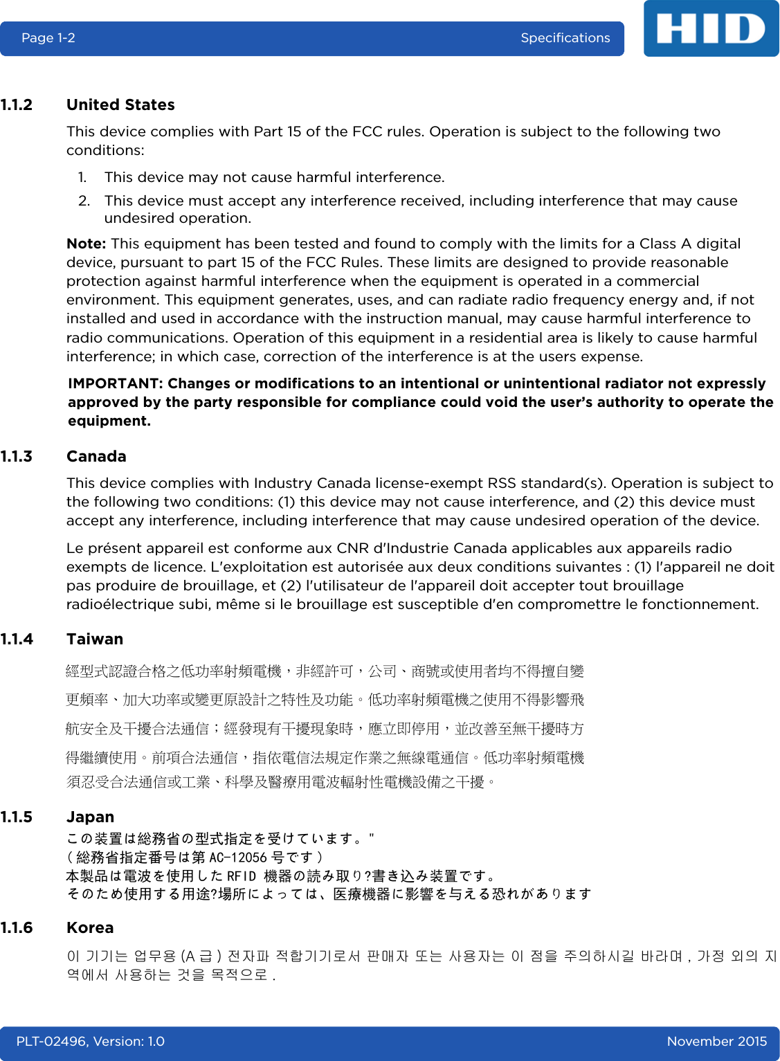
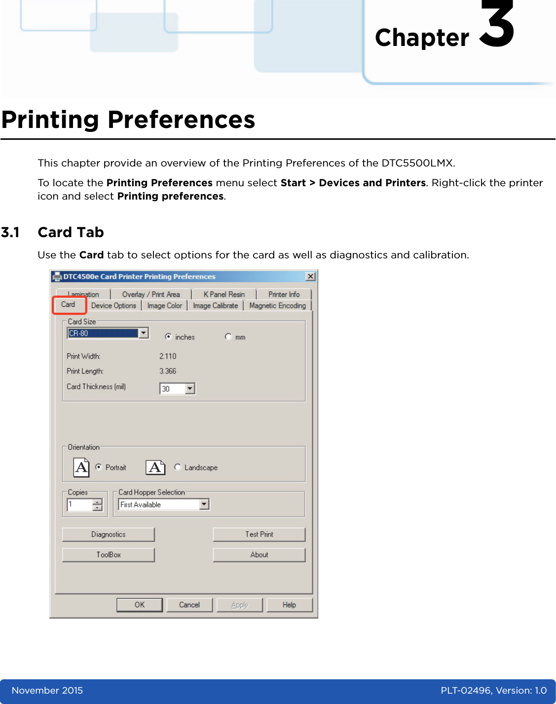
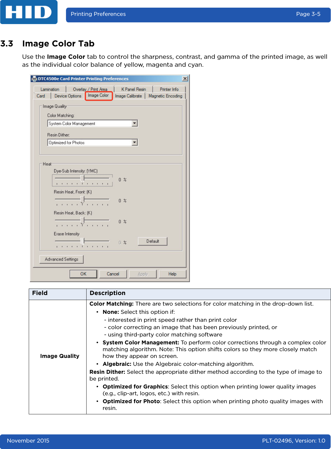
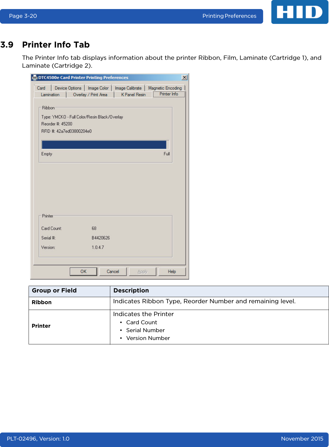
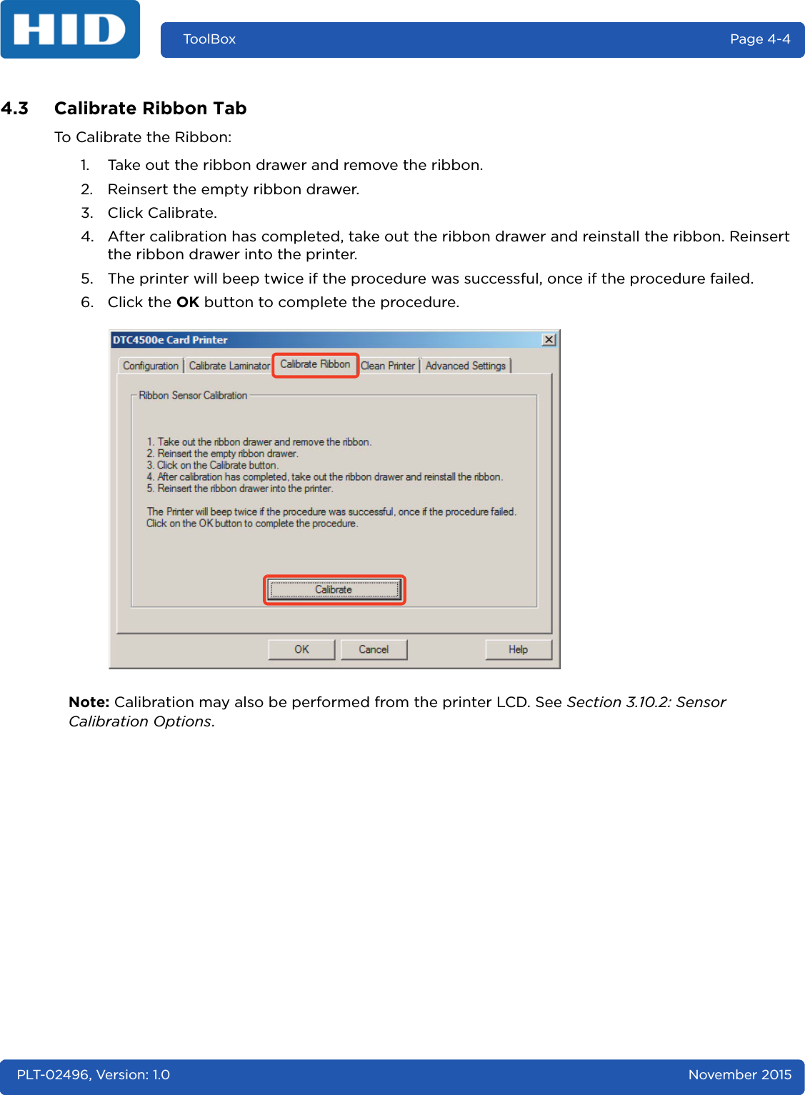
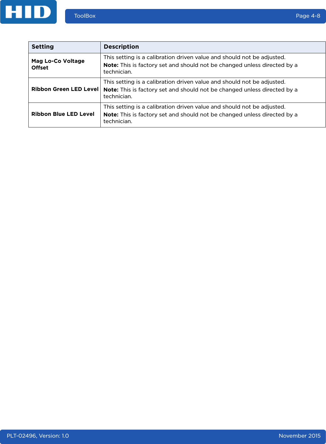
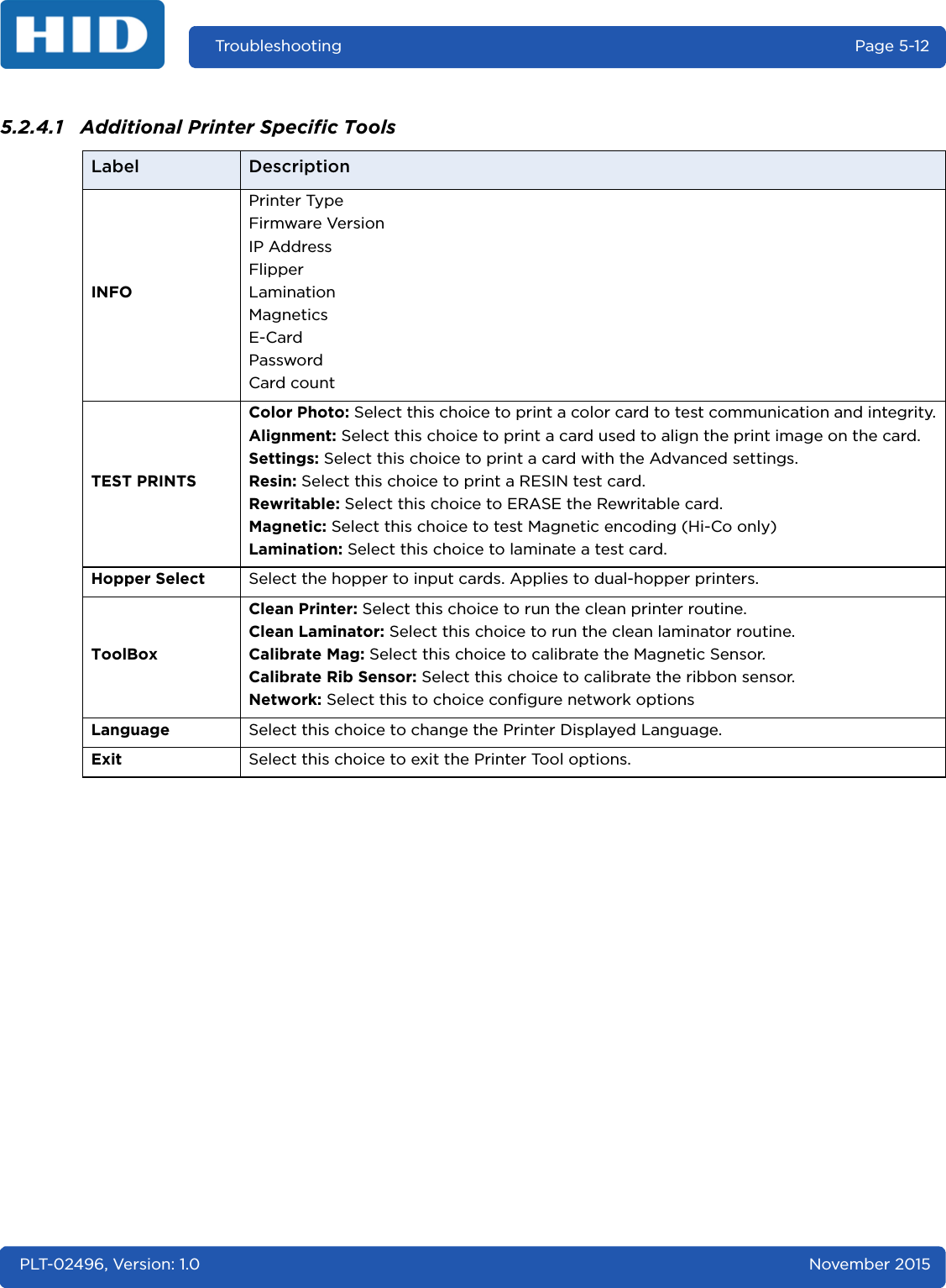
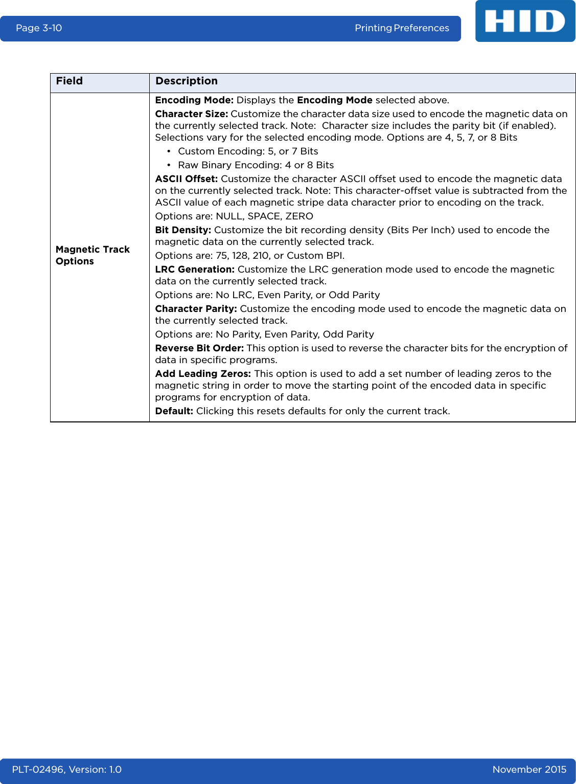
![November 2015 PLT-02496, Version: 1.0Printing Preferences Page 3-93.5 Magnetic Encoding TabSelect the Magnetic Encoding tab to configure the Magnetic Stripe encoding process. These options are only available if the printer has an optional Magnetic Stripe Encoding Module installed.Field DescriptionEncoding OptionsEncoding Mode: Change the encoding mode and coercivity setting or modify the ISO standards for tracks 1, 2 and 3. Options are:• ISO Encoding (see Section 3.5.1: ISO Encoding Option)•Custom Encoding (see Section 3.5.2: Custom Encoding Option)• Raw Binary Encoding (see Section 3.5.3: Raw Binary Encoding Option)• JIS II Encoding (see Section 3.5.4: JIS II Encoding Option)Coercivity: Select the coercivity option (Oersted [Oe]) for the magnetic stripe type that matches the card type.• High Coercivity = 4000 Oersted • FARGO’s High Coercivity UltraCard IIIs are 2750 Oersted• Medium Coercivity = 600 Oersted• Low Coercivity = 300 OerstedShift Data Left: Select this option to shift the recorded magnetic data to the left-hand side of the card's magnetic stripe. This is useful in situations that require cards to be readable with insert type readers](https://usermanual.wiki/HID-Global/X002100/User-Guide-2944396-Page-31.png)
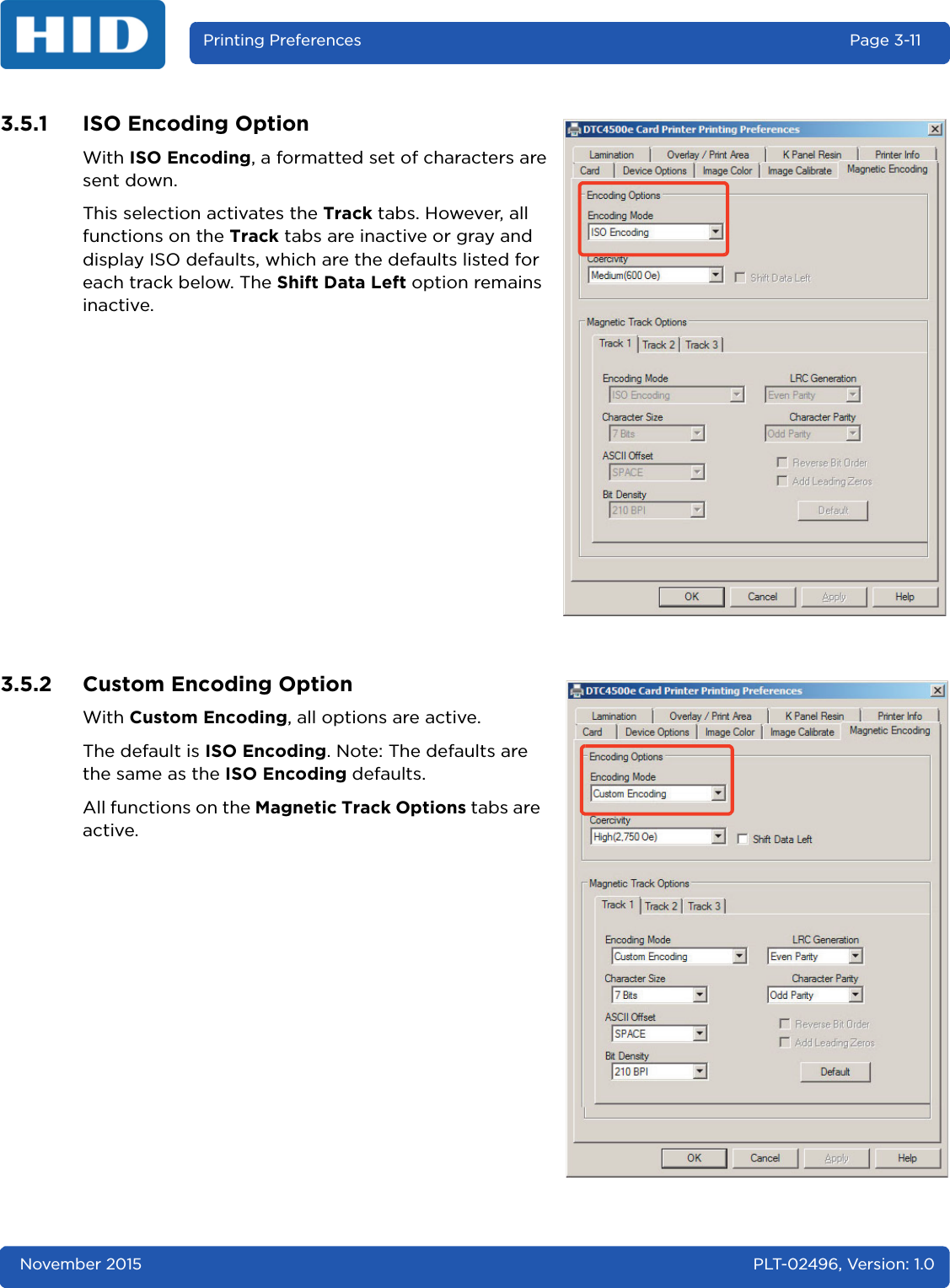
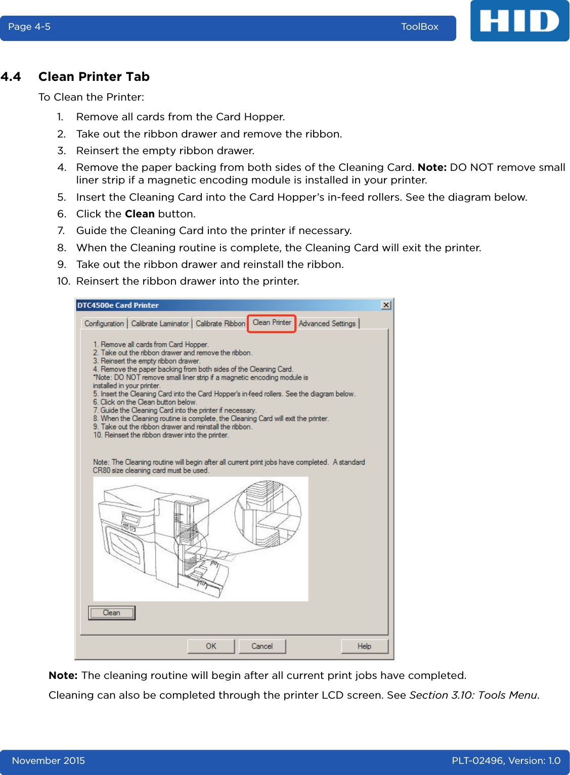
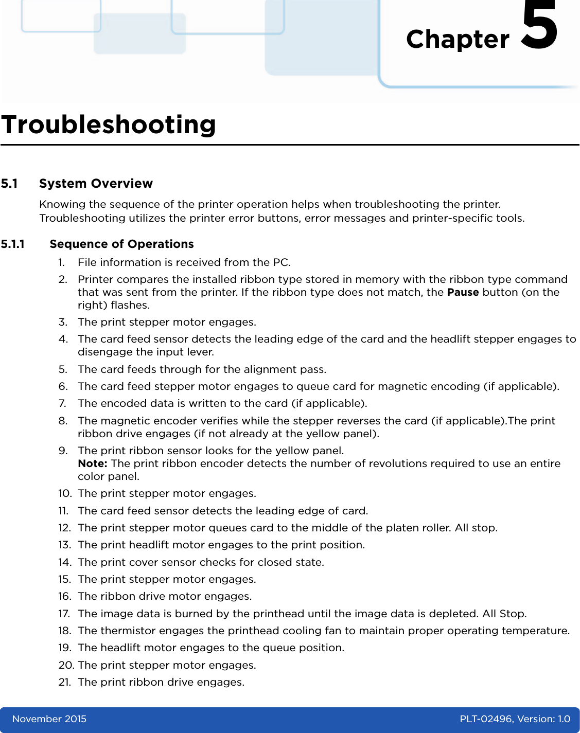
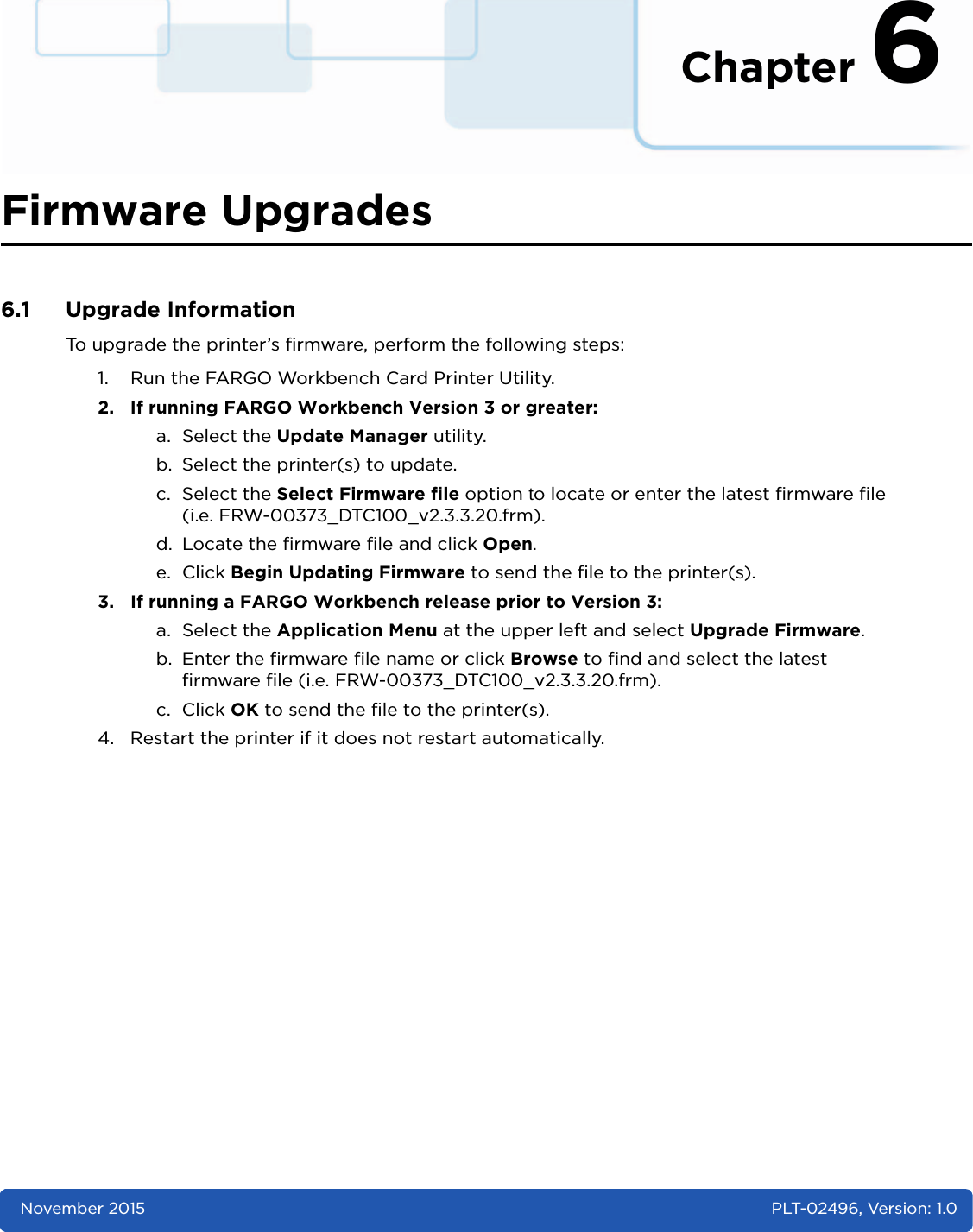
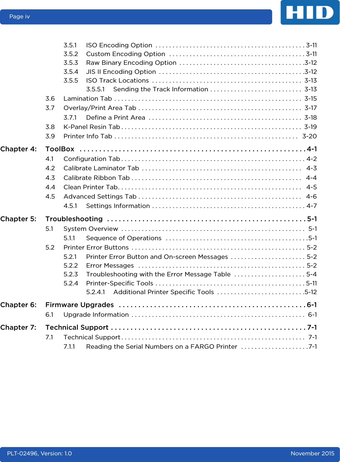
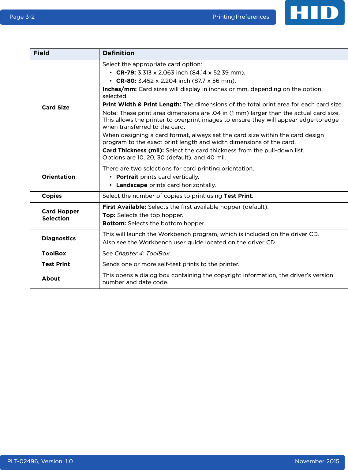
![Page 3-14 Printing Preferences PLT-02496, Version: 1.0 November 2015Reviewing the Sample StringTrack 1: ~1%JULIEANDERSON^1234567890?Track 2: ~2;1234567890987654321?Track 3: ~3;1234567890987654321?ASCII Code and Character TableTrack Start SentinelEnd SentinelField Separator Valid Characters Maximum Number of CharactersTrack 1 % ? ^ ASCII 32-95 (See the table) 78Track 2 ; ? = ASCII 48-63 (See the table) 39Track 3 ; ? = ASCII 48-63 (See the table) 106ASCII Code Character ASCII Code Character ASCII Code Character32 space 54 6 76 L33 ! 55 7 77 M34 56 8 78 N35 # 57 9 79 O36 $ 58 : 80 P37 % 59 ; 81 Q38 and 60 < 82 R39 ' 61 = 83 S40 ( 62 > 84 T41 ) 63 ? 85 U42 * 64 @ 86 V43 + 65 A 87 W44 ' 66 B 88 X45 - 67 C 89 Y46 . 68 D 90 Z47 / 69 E 91 [48 0 70 F 92 \49 1 71 G 93 ]50 2 72 H 94 ^51 3 73 I 95 _52 4 74 J53 5 75 K](https://usermanual.wiki/HID-Global/X002100/User-Guide-2944396-Page-36.png)
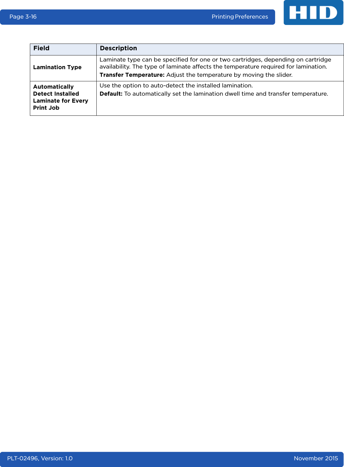
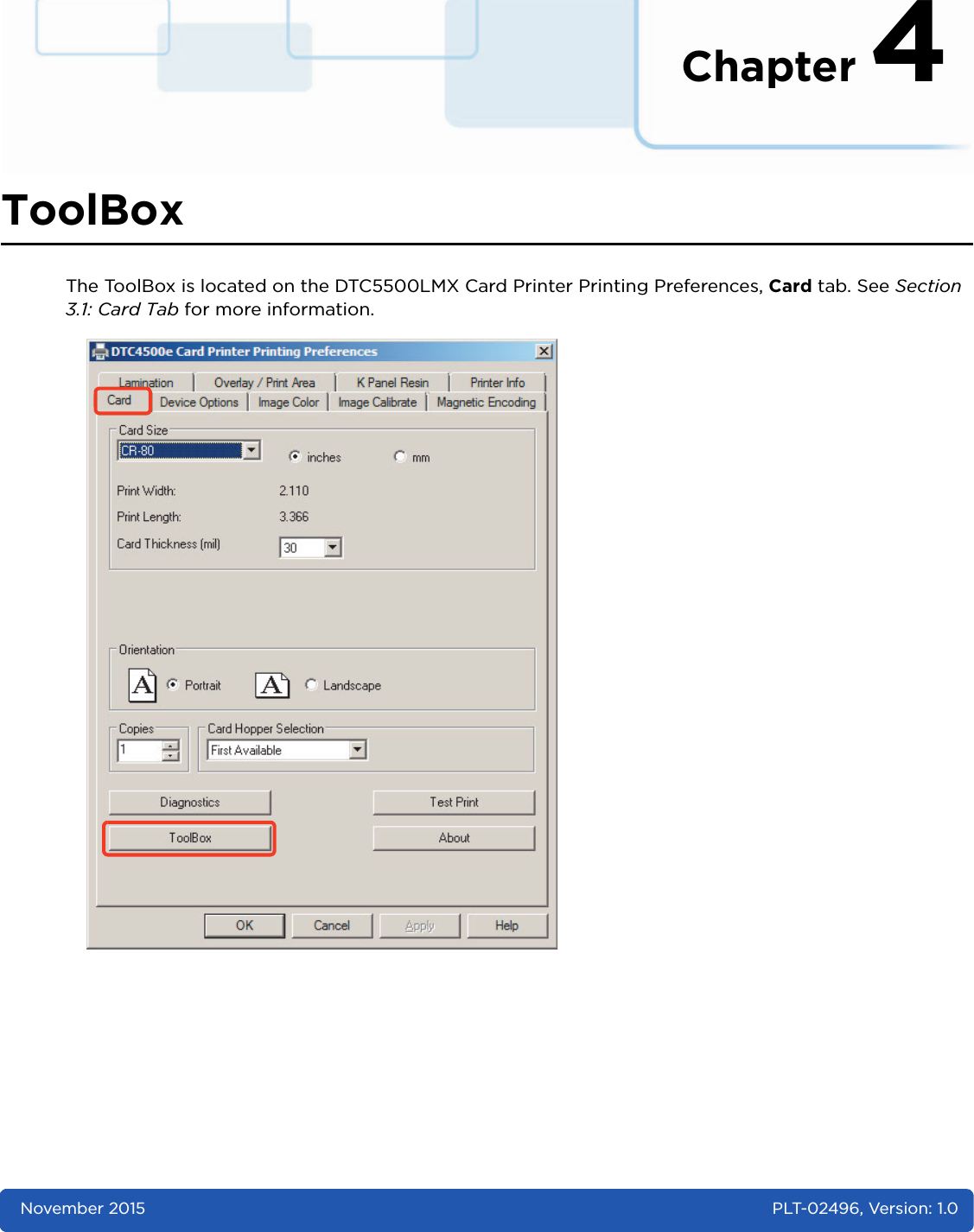
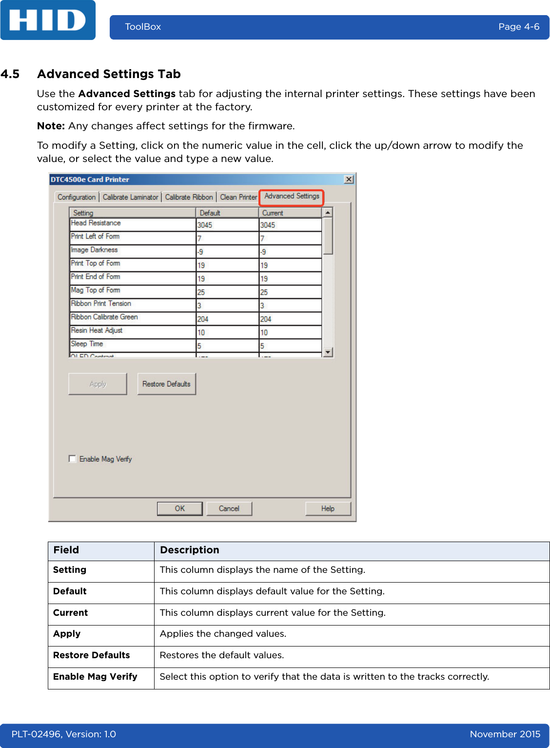
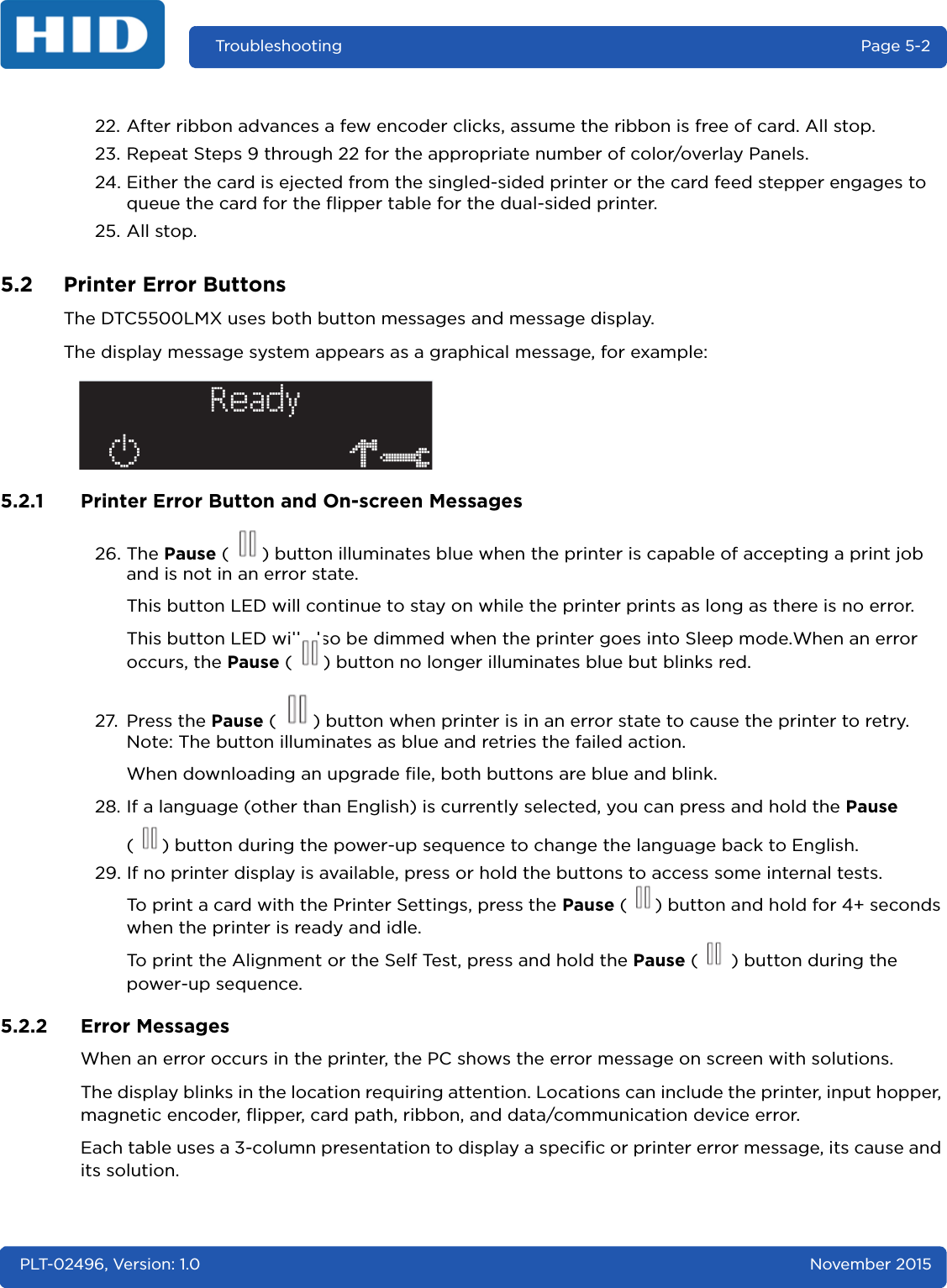
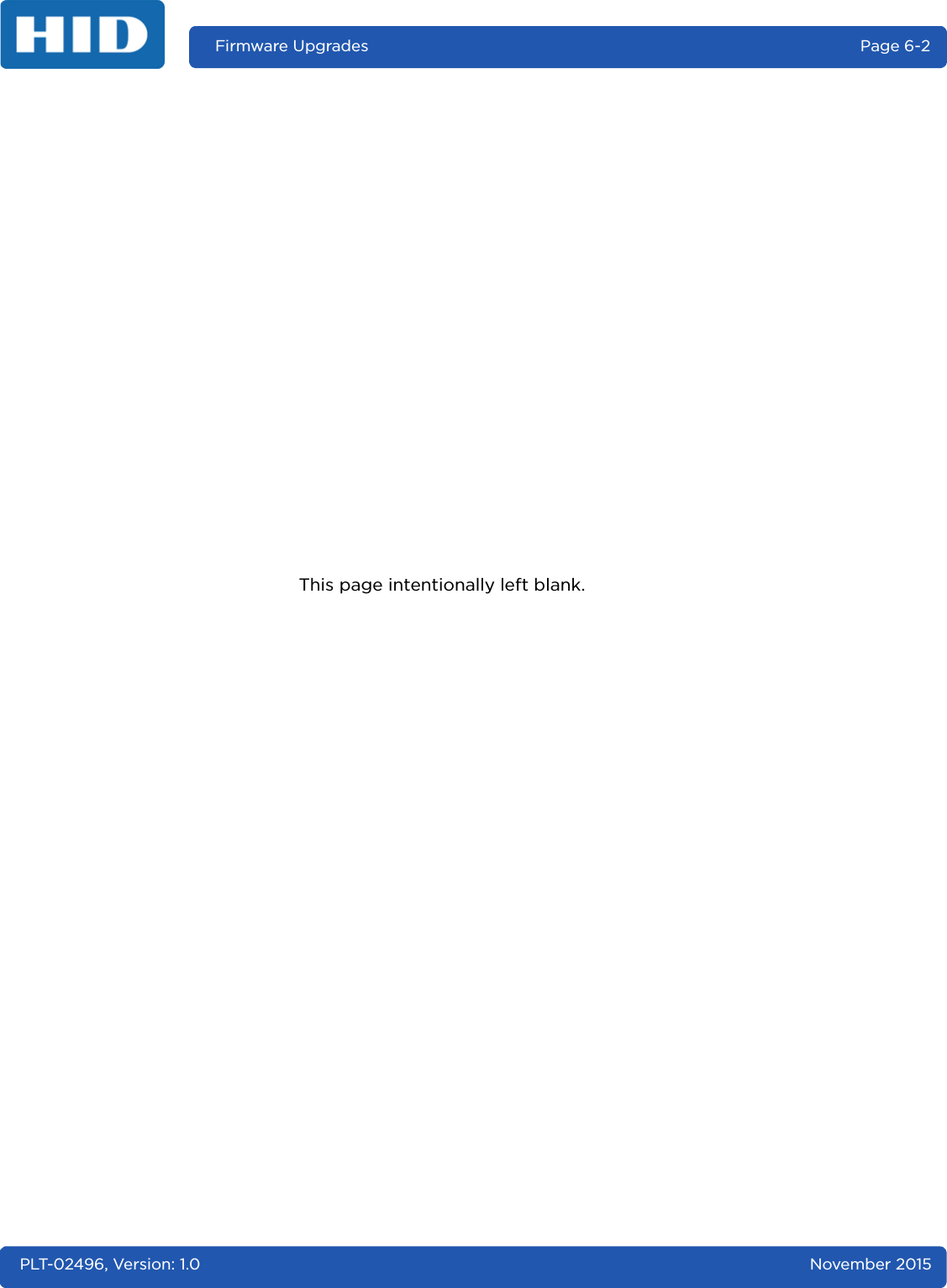
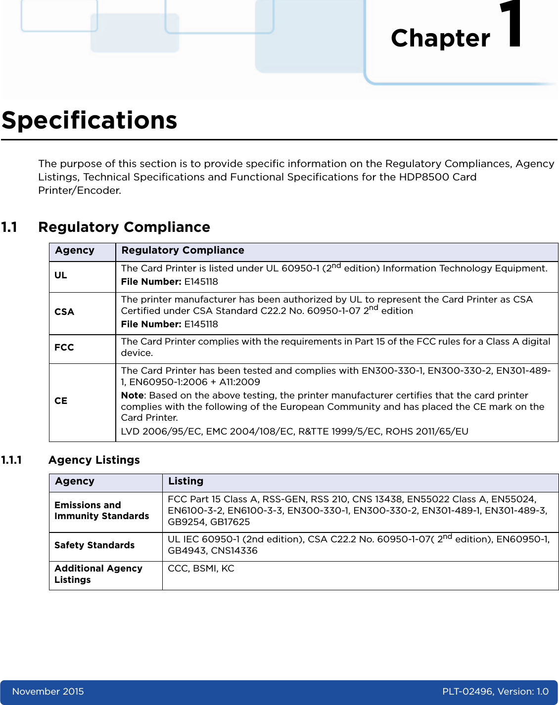
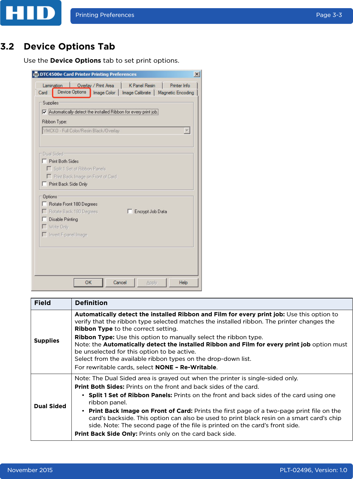
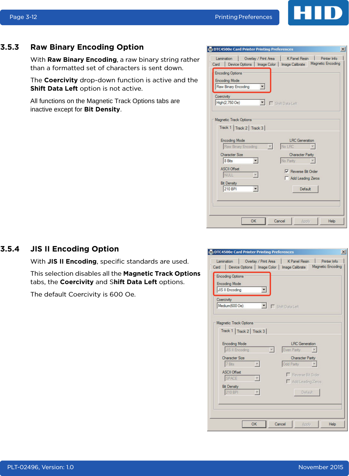
![November 2015 PLT-02496, Version: 1.0Printing Preferences Page 3-153.6 Lamination TabThese options allow control of the printer's lamination process. When no laminator is detected, the lamination tab is active but all functions are disabled.Field DescriptionLamination PositionUse this control to adjust the horizontal position of the laminate. Only the horizontal position needs adjustment. Default is 0.To adjust the position, click on the horizontal adjustment arrows. The adjustment arrows point in the direction the patch will move on the card. The maximum horizontal value is 100 Pixels (10 Pixels = 0.03 [0.8mm]).Lamination SpeedTransfer Dwell Time: Adjust this control for the throughput speed of a card in seconds per inch, default is 2.0 seconds per inch.• Maximum Limit - 4.9 seconds per inch• Minimum Limit - 0.8 seconds per inchLamination SideSpecify the side(s) of the card to laminate:• No Lamination •Front•Back •Both](https://usermanual.wiki/HID-Global/X002100/User-Guide-2944396-Page-37.png)