HM Electronics 1402 Wireless headset User Manual Installation Instructions
HM Electronics Inc Wireless headset Installation Instructions
UserManual.wiki
>
HM Electronics
>
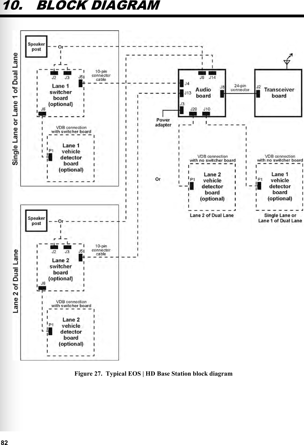
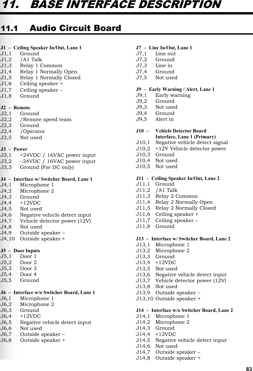
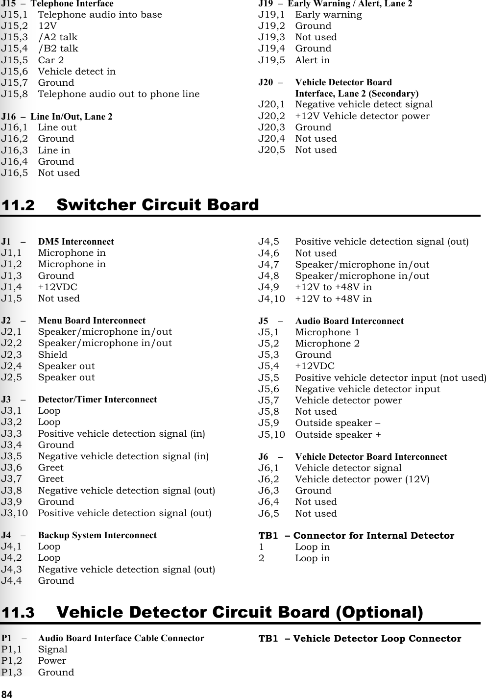
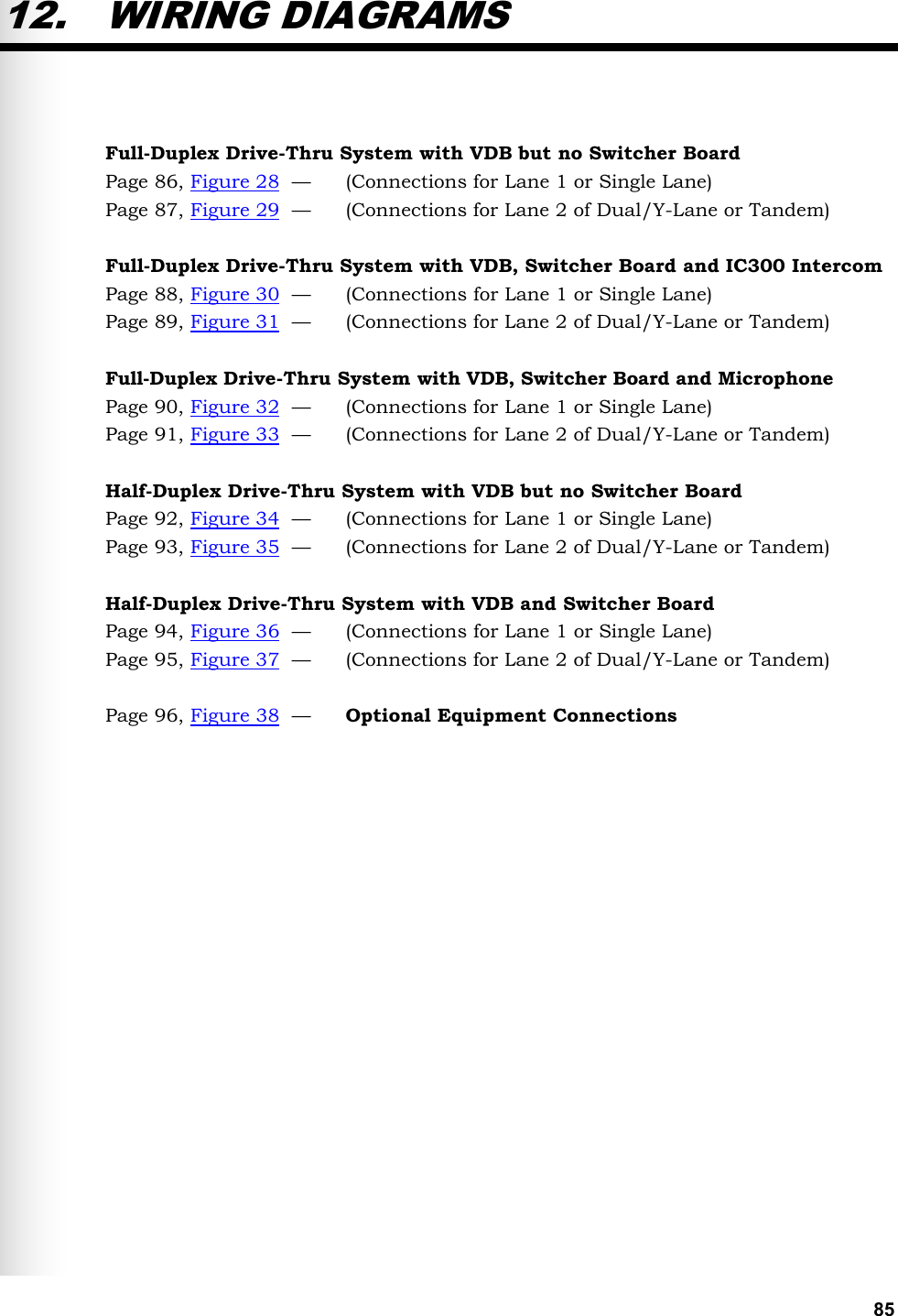
1402 User Manual
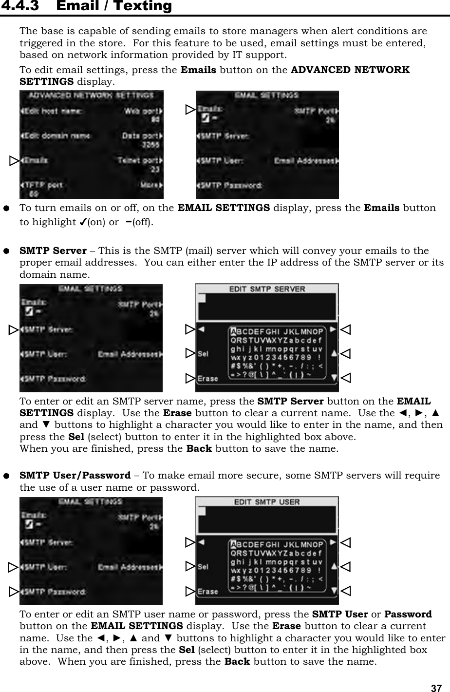
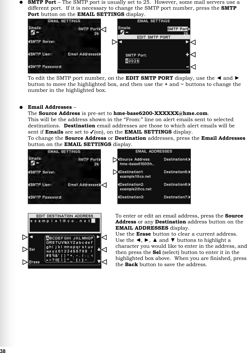
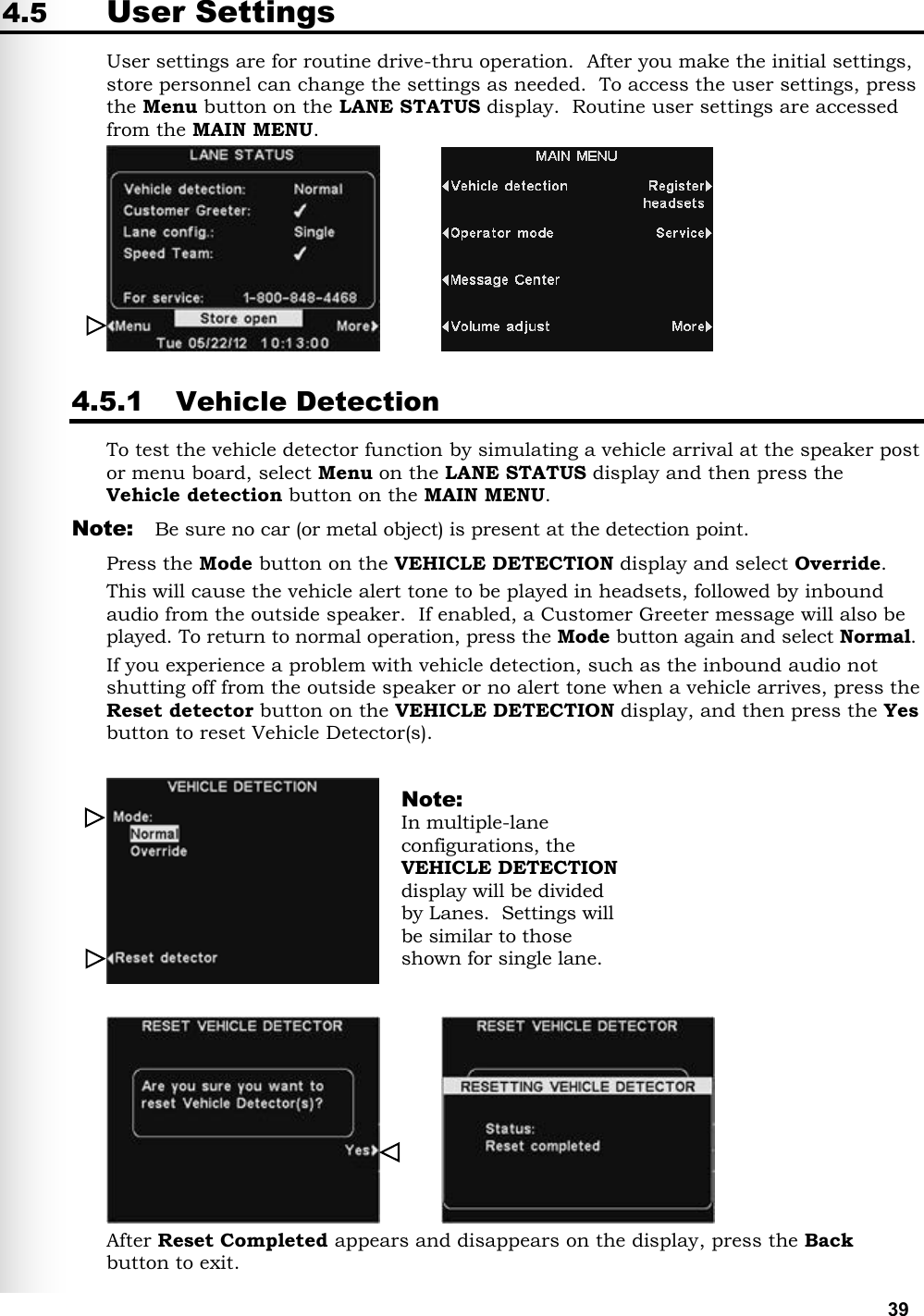
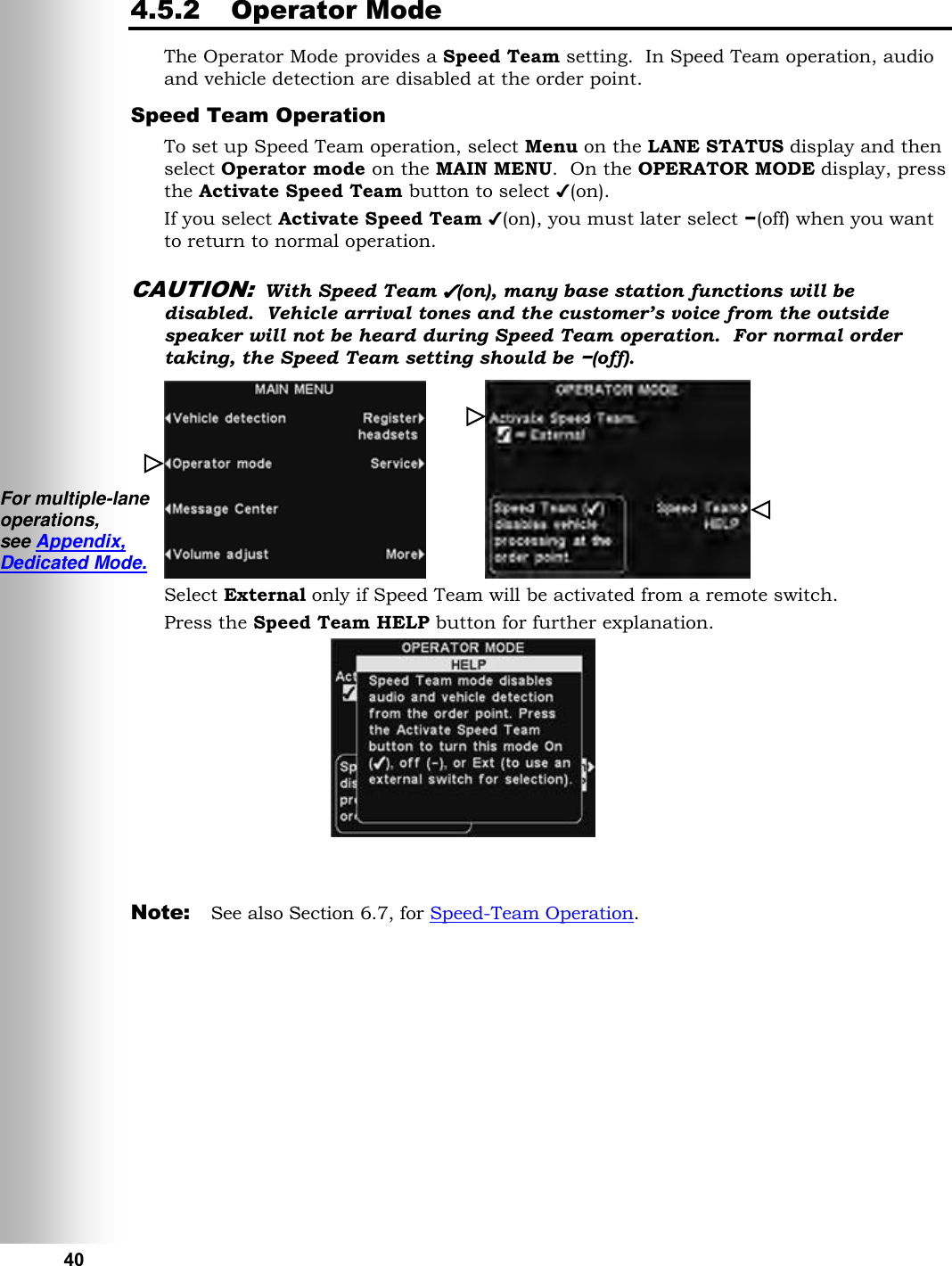
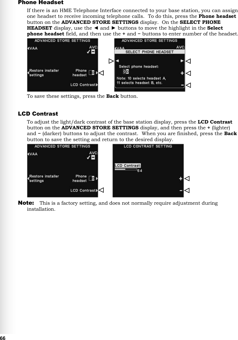
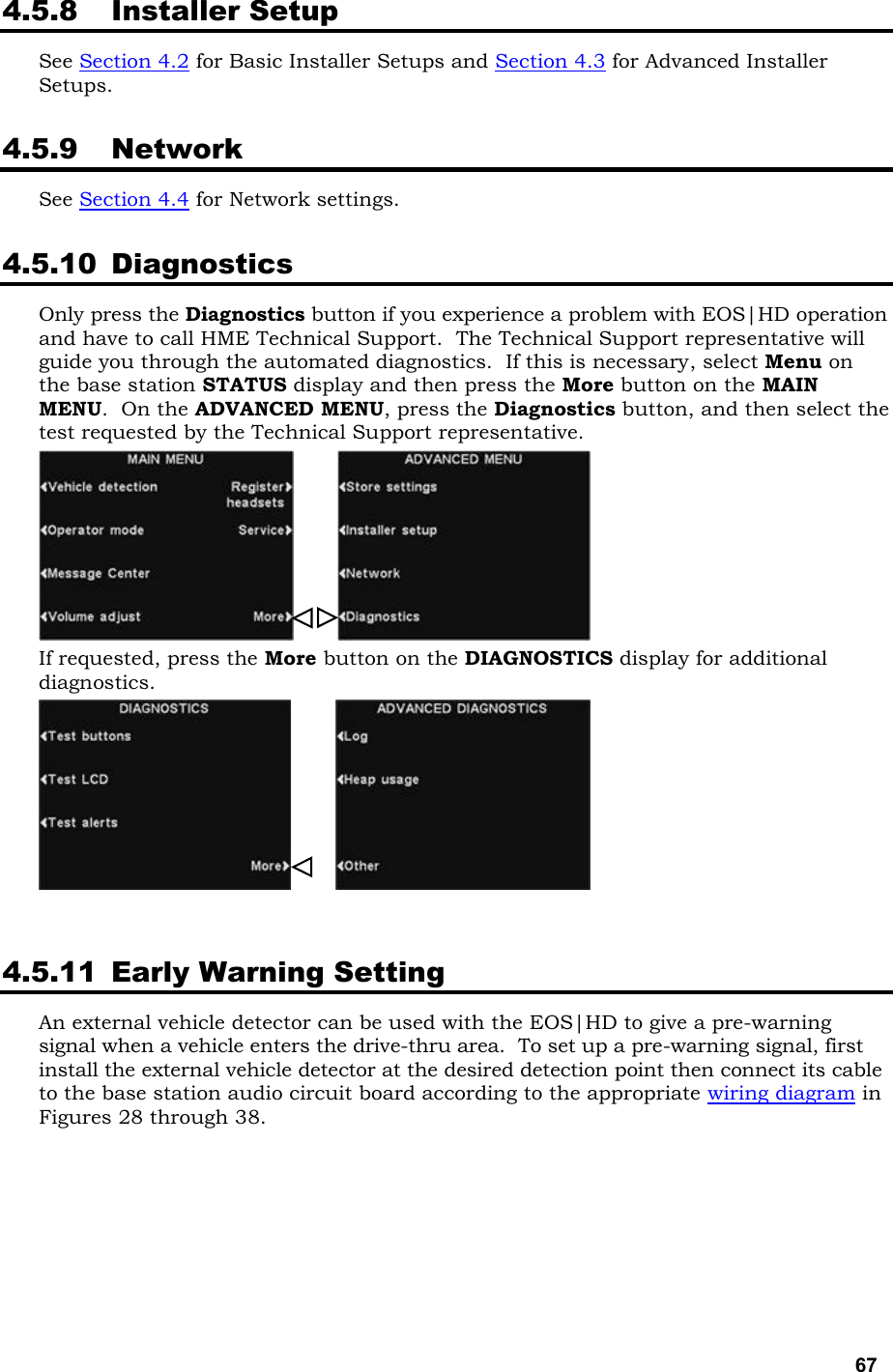
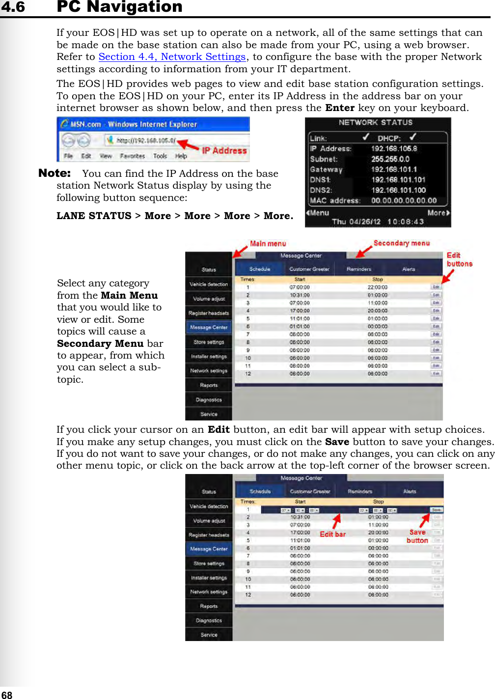
Users Manual
Navigation menu
Upload a User Manual
Namespaces
Wiki Guide
HTML
PDF
Info
Views
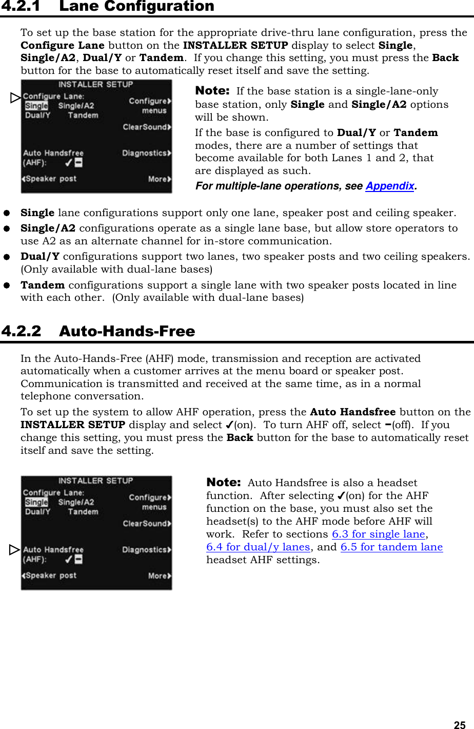
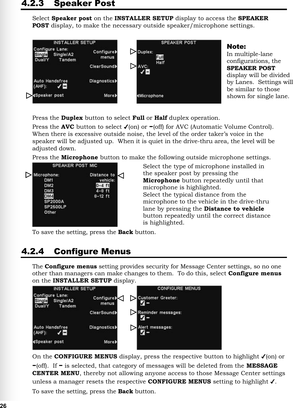
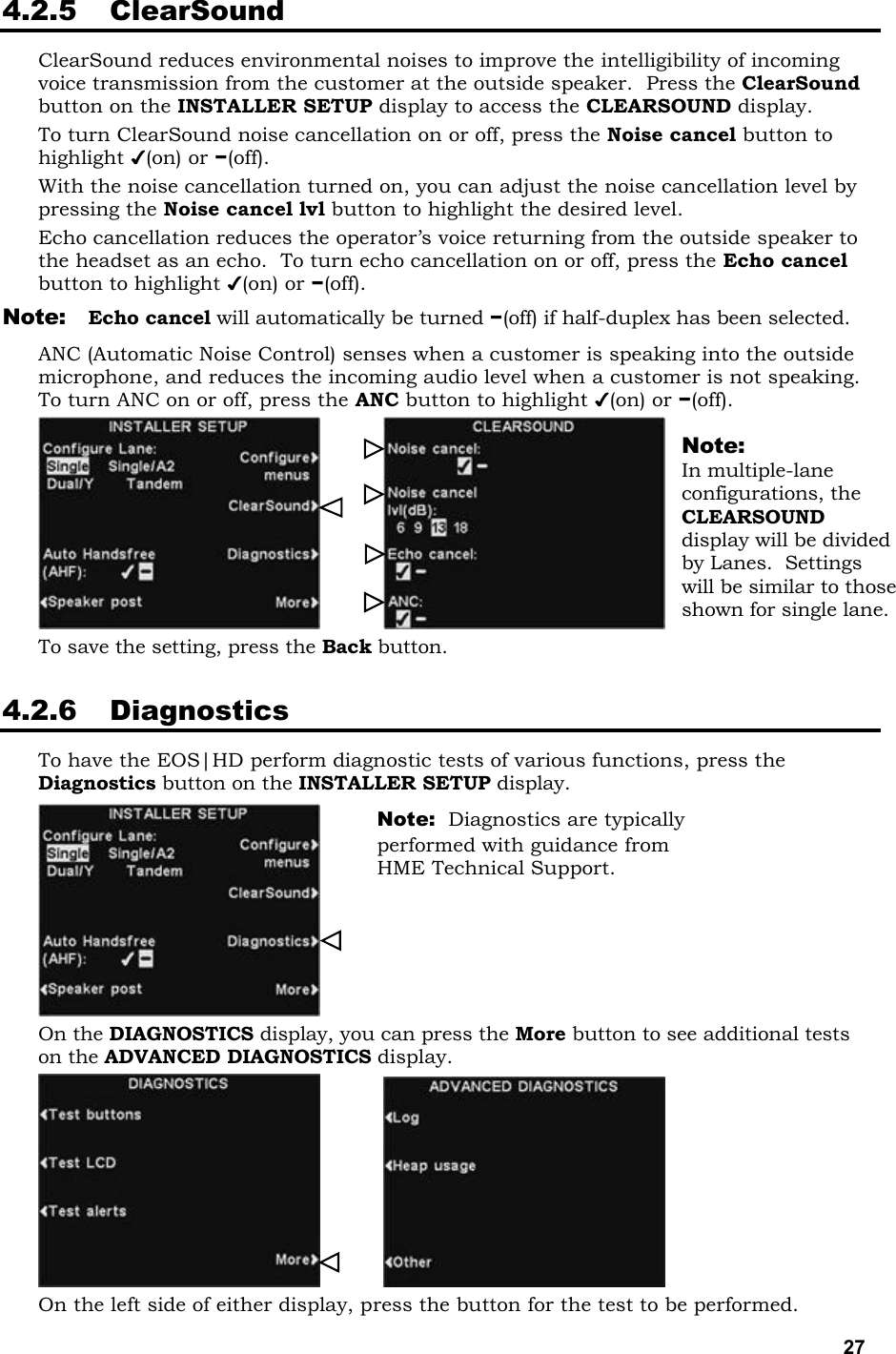
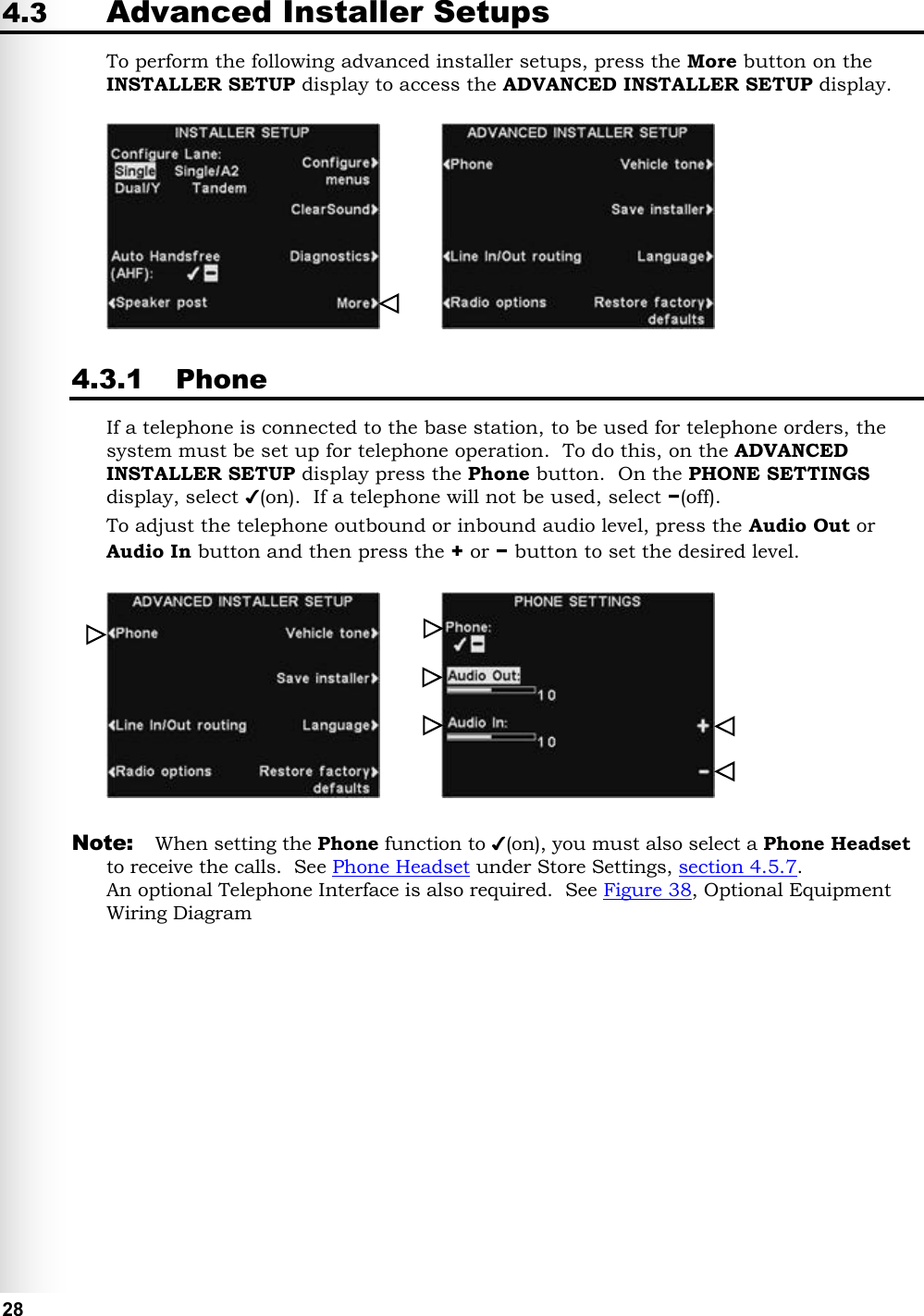
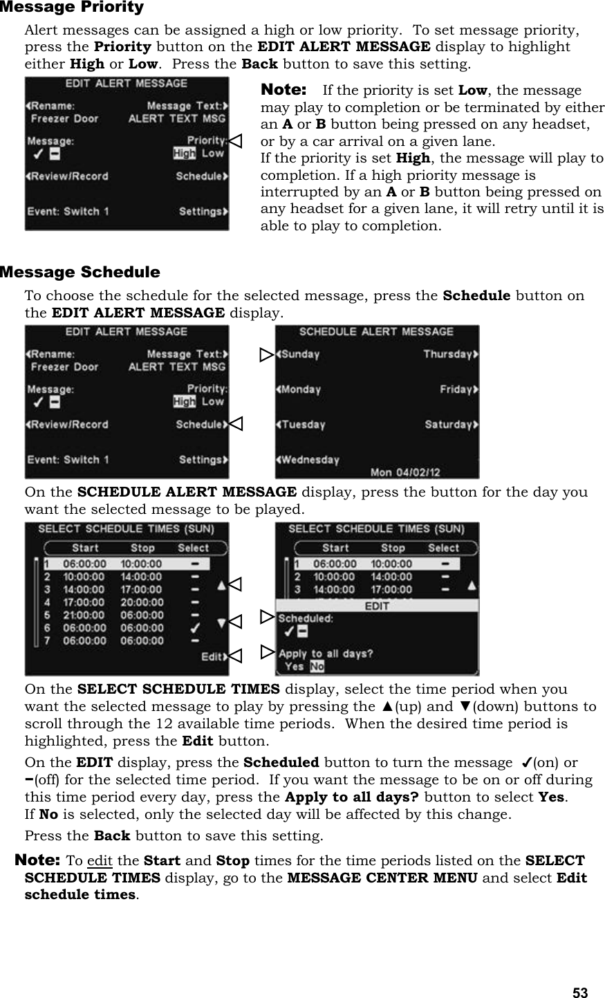
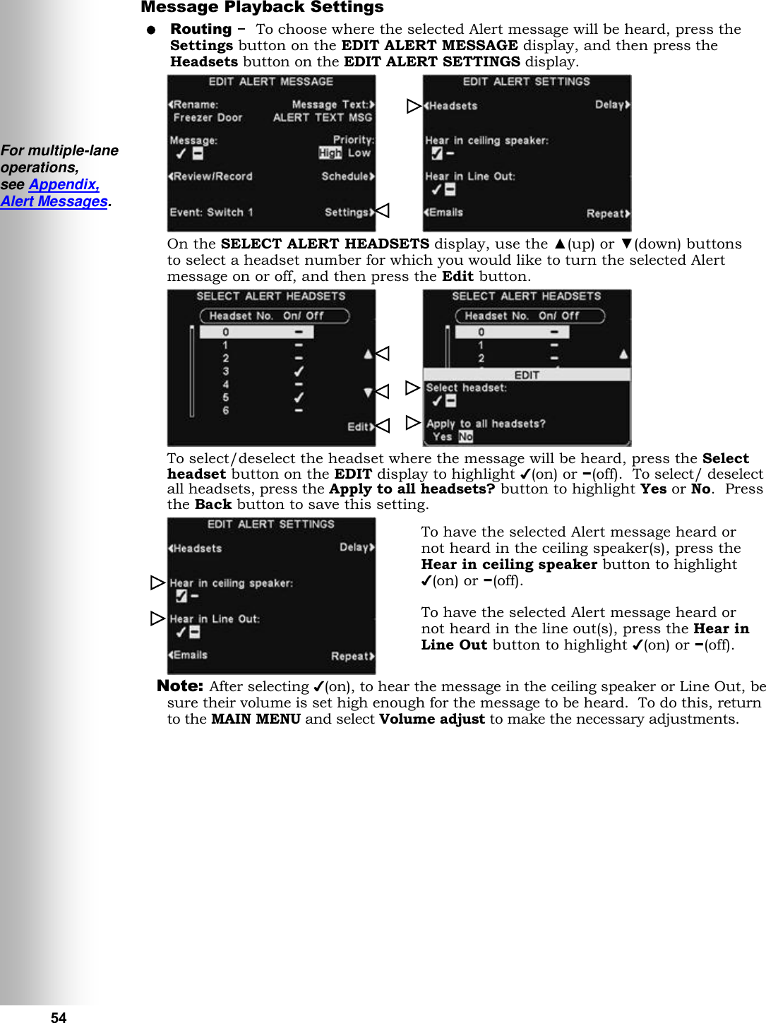
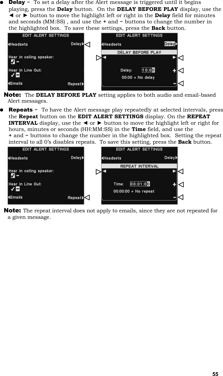
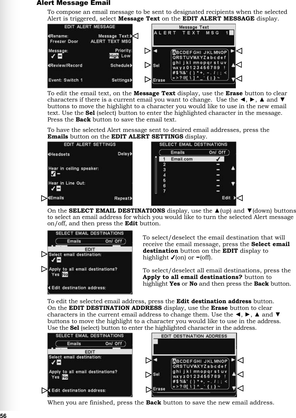
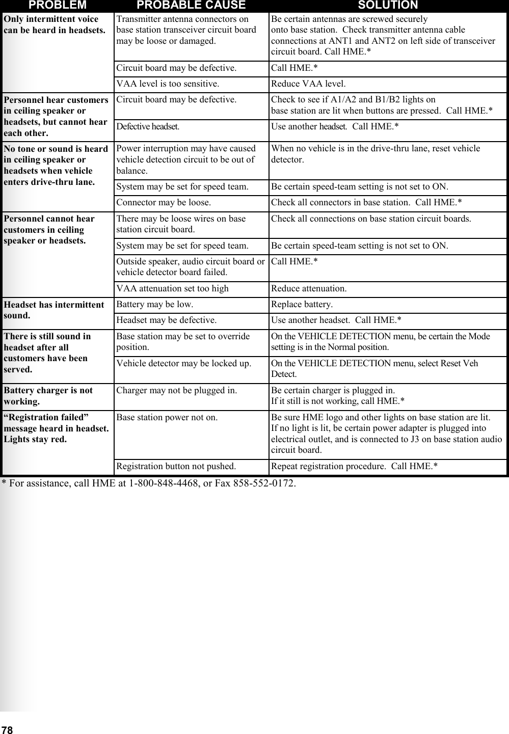
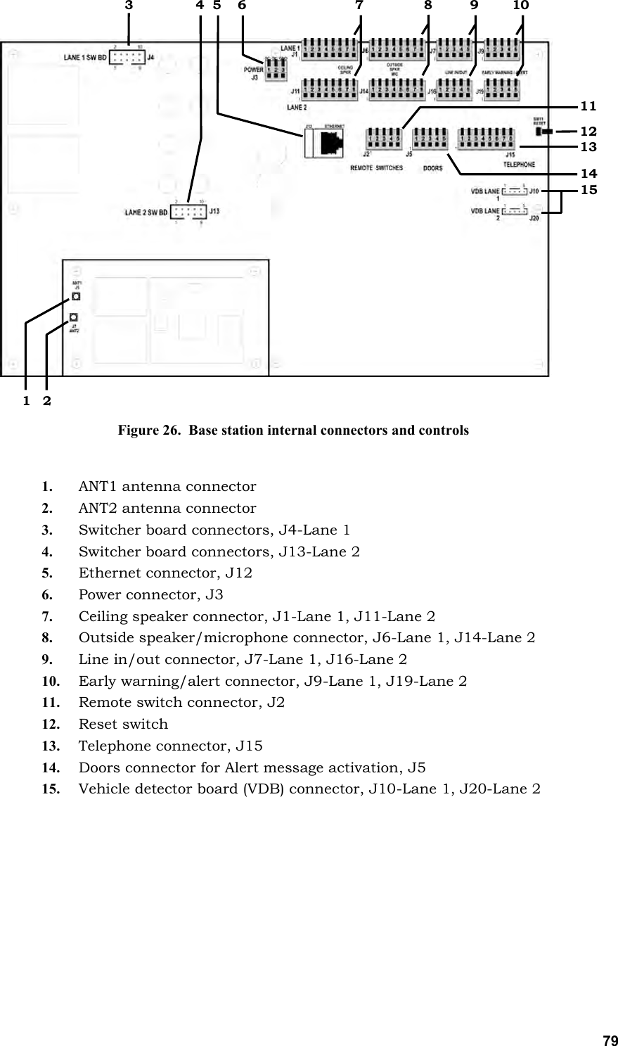
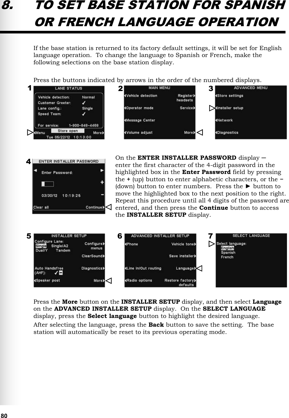
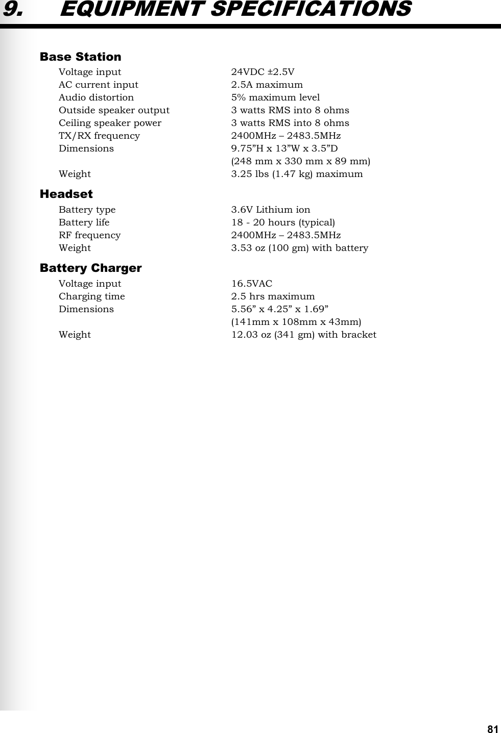
User Manual
Discussion / Help
Navigation