HM Electronics BP850 BELTPACK TRANSCEIVER User Manual 400520
HM Electronics Inc BELTPACK TRANSCEIVER 400520
UserManual.wiki
>
HM Electronics
>
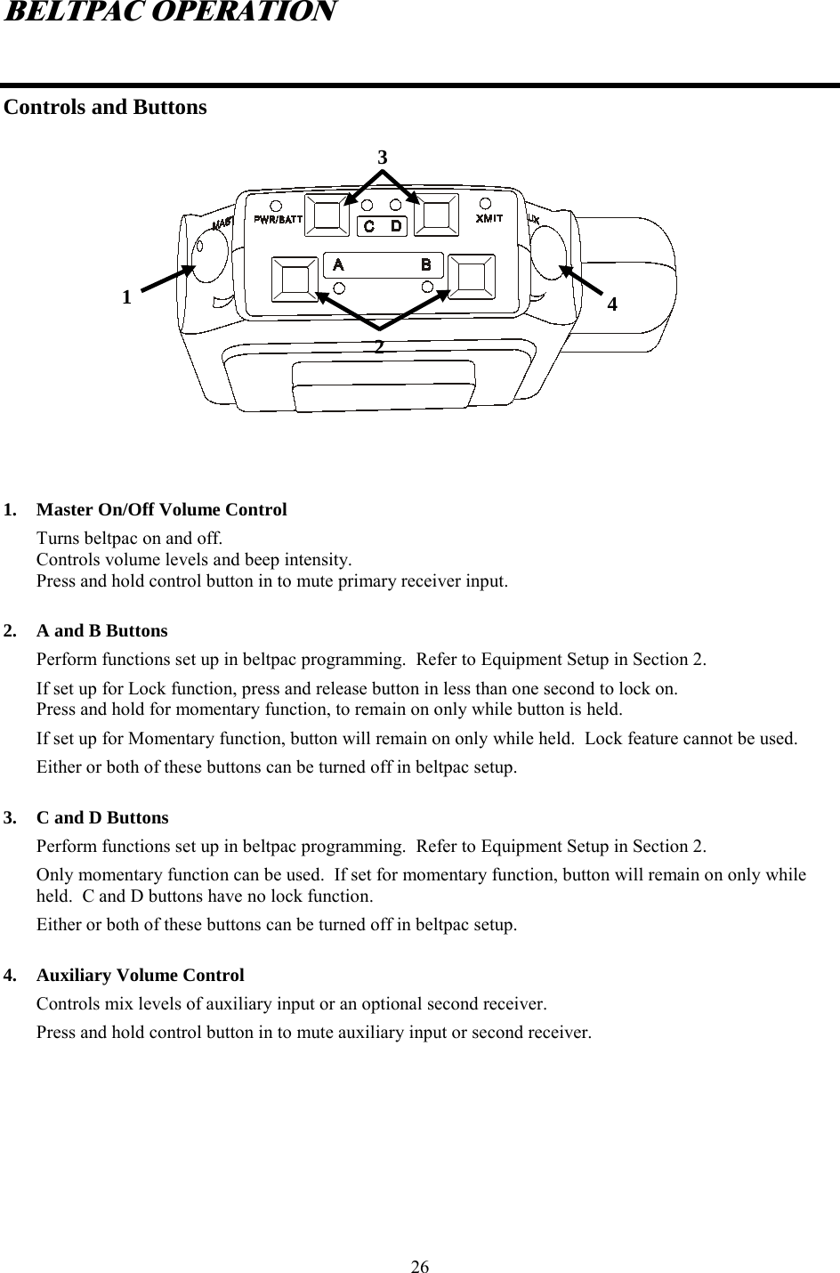
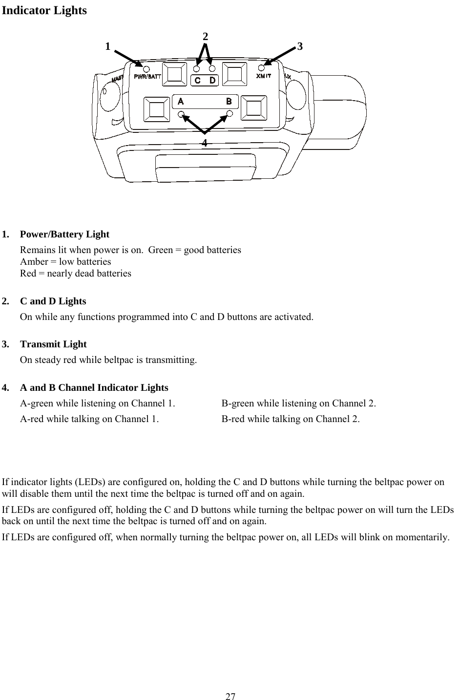
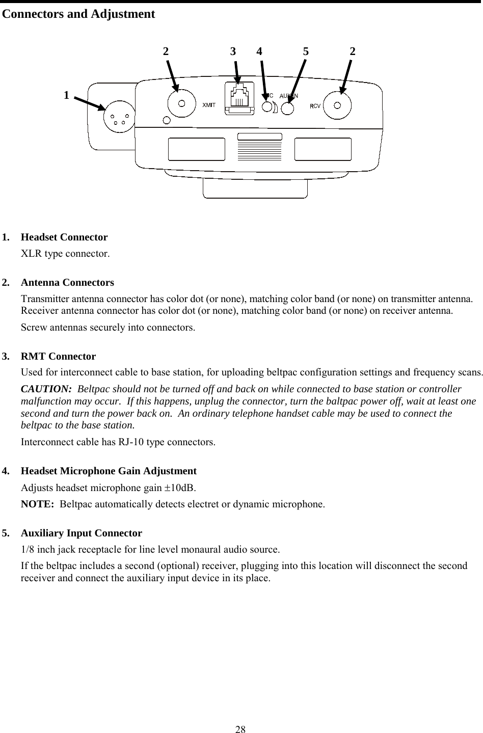
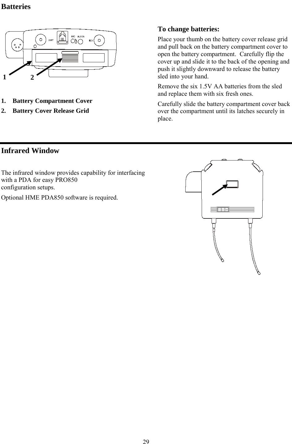
BP850 User Manual
MANUAL
Navigation menu
Upload a User Manual
Namespaces
Wiki Guide
HTML
PDF
Info
Views
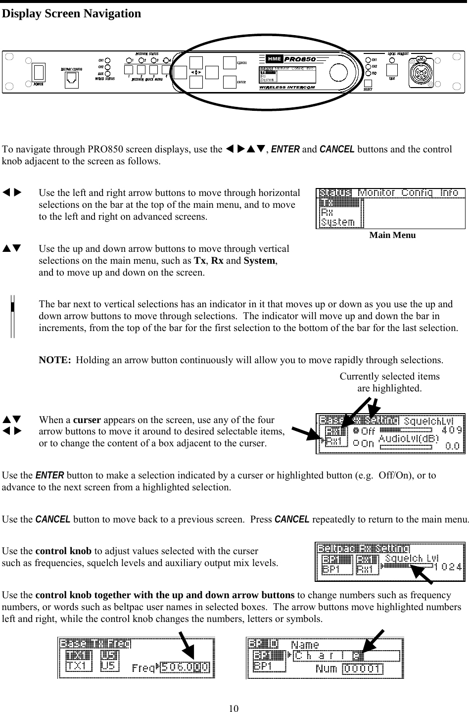
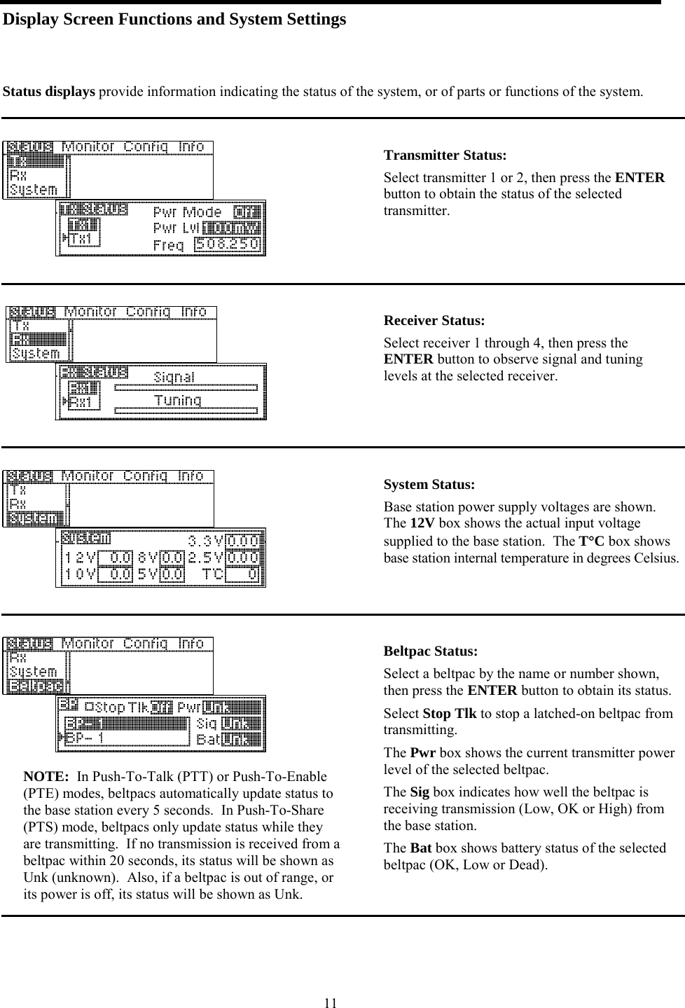
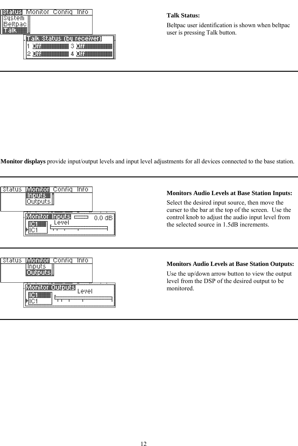
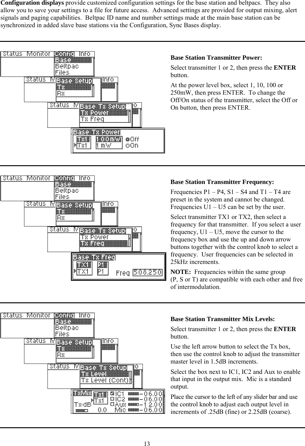
User Manual
Discussion / Help
Navigation