HM Electronics BP850 BELTPACK TRANSCEIVER User Manual 400520
HM Electronics Inc BELTPACK TRANSCEIVER 400520
MANUAL
HME# 400520
Rev − 7/7/03
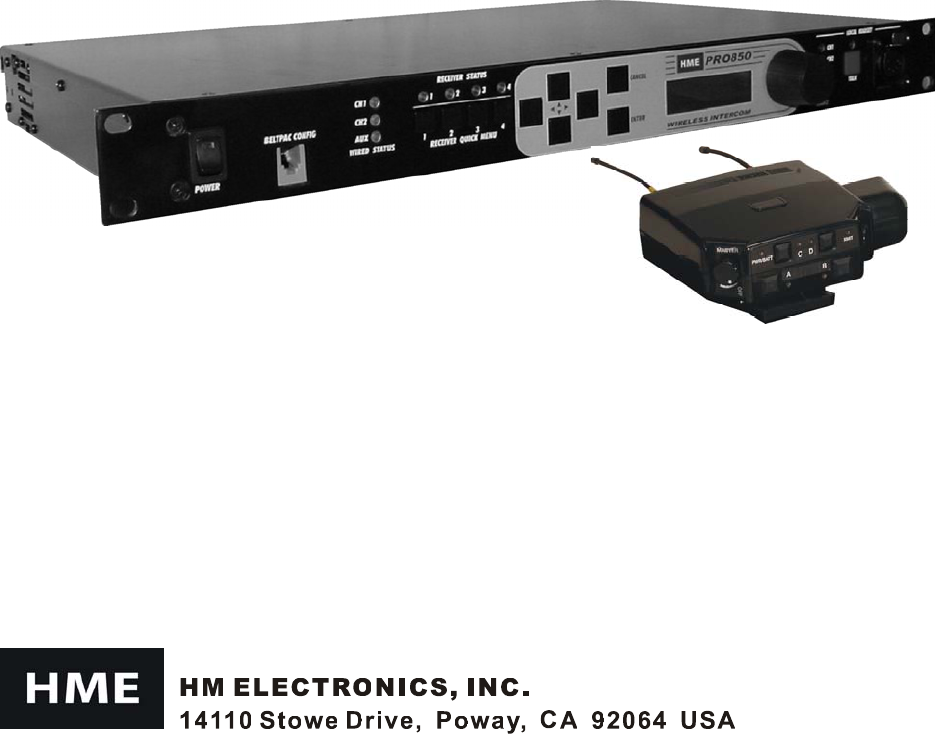
PRO850
Wireless Intercom
Operating Instructions

Table of Contents
SECTION 1. INTRODUCTION ....................................................................................................................1
EQUIPMENT FEATURES................................................................................................................................2
Base Station Front Panel Features ..................................................................................................................2
Base Station Rear Panel Features ...................................................................................................................2
Beltpac Top Panel Features ............................................................................................................................3
Beltpac Bottom Panel Features.......................................................................................................................3
BLOCK DIAGRAMS ........................................................................................................................................4
Base Station....................................................................................................................................................4
Beltpac............................................................................................................................................................4
EQUIPMENT SPECIFICATIONS ....................................................................................................................5
Base Station....................................................................................................................................................5
Beltpac............................................................................................................................................................6
SECTION 2. EQUIPMENT SETUP..............................................................................................................7
BASE STATION SETUP...................................................................................................................................7
Checking Status.......................................................................................................................................11
Monitoring Audio Levels ........................................................................................................................12
Base Transmitter Configuration ..............................................................................................................13
Base Receiver Configuration...................................................................................................................14
Base Configuration..................................................................................................................................15
Beltpac Configuration .............................................................................................................................18
Saving and Loading Settings...................................................................................................................21
Advanced Settings...................................................................................................................................21
Displaying Information ...........................................................................................................................25
Diagnostics..............................................................................................................................................25
SECTION 3. PRO850 OPERATION............................................................................................................9
BASE STATION OPERATION ........................................................................................................................9
Uses of Front Panel Controls, Indicators and Connectors ..............................................................................9
Display Screen Navigation ...........................................................................................................................10
Display Screen Functions and System Settings............................................................................................11
BELTPAC OPERATION.................................................................................................................................26
Controls and Buttons ....................................................................................................................................26
Indicator Lights ............................................................................................................................................27
Connectors and Adjustment..........................................................................................................................28
Batteries........................................................................................................................................................29
Infrared Window ..........................................................................................................................................29
SECTION 4. PC850 SOFTWARE...............................................................................................................30
PC850 Installation ........................................................................................................................................30
PC850 Operation ..........................................................................................................................................31
END-USER LICENSE AGREEMENT FOR HME PC850 SOFTWARE...................................................33
Copyright HM Electronics, Inc. - July 2003

FCC LICENSING
The HME PRO850 is Type Accepted under Part 74 of the United States Federal Communications
Commission (FCC) Code of Federal Regulations governing general purpose applications. The system
requires an FCC station license if operated within the United States or its possessions. Licensing of this
equipment is the User’s responsibility. Licensability depends on the User’s classification, equipment
application and frequency selected. The user should contact the appropriate telecommunications authority
for any desired clarification.
CAUTION: Changes or modifications made by the user could void the user’s authority to operate
PRO850 equipment.
MANDATORY SAFETY INSTRUCTIONS
FOR BASE STATION INSTALLERS AND USERS
1. Use only manufacturer or dealer supplied antennas. Antenna minimum safe distance, as calculated
from FCC requirements, is 4.8cm. However, the FCC default for minimum safe distance is 20cm.
Antenna gain: zero dBi referenced to a monopole.
2. The Federal Communications Commission has adopted a safety standard for human exposure to RF
(Radio Frequency) energy, which is below the OSHA (Occupational Safety and Health Act) limits.
3. To comply with current FCC RF exposure limits, the antenna must be installed at or exceeding the
minimum safe distance described here, and in accordance with the requirements of the antenna
manufacturer or supplier.
4. Antenna substitution: Do not substitute any antenna for the one supplied by or recommended by the
manufacturer or radio dealer. You may be exposing person or persons to harmful radio frequency
radiation. You may contact your radio dealer or the manufacturer for further instructions.
5. WARNING: Maintain a separation distance from the antenna to person(s) of at least 20cm.
You, as the qualified end-user of this radio device must control the exposure conditions of bystanders
to ensure the minimum separation distance (above) is maintained between the antenna and nearby
persons for satisfying RF exposure compliance.
Operation of this transmitter must satisfy the requirements of the General Population/Uncontrolled
Exposure Environment for work-related use. Transmit only when person(s) are at least the minimum
distance from the properly installed, externally mounted antenna.
1
PRO850 equipment operates in the UHF band from 470 MHz to 740 Hz in 18 MHz subsets. Transmitters and
receivers operate in different, non-adjacent 18 MHz bands. Synthesized frequencies can be selected in 25 kHz
increments over each 18 MHz band, for 720 transmit and 720 different receive frequencies.
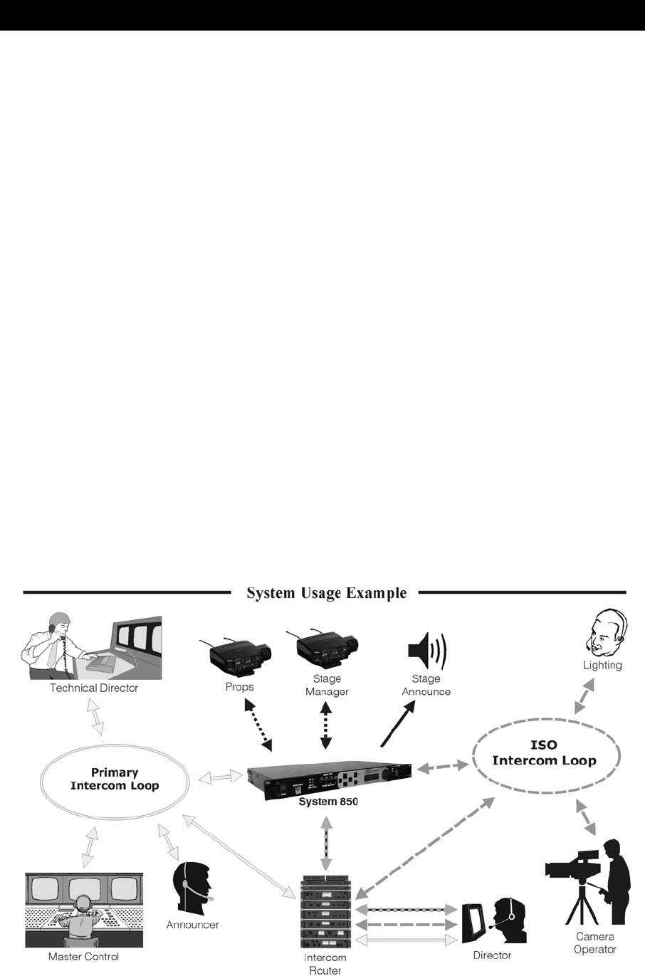
Base stations can be configured with up to four receivers and two transmitters, supporting up to four Beltpacs in
full-time transmit, full-duplex operation. Two or three base stations interconnected can support up to twelve
beltpacs operating at once. The channel lockout feature supports several beltpacs sharing the same frequency.
In this mode, one beltpac user on a shared frequency can transmit at a time. If another user is already transmitting
on that frequency, a “busy” signal will be heard. A total of sixteen beltpacs can be used with a system.
A feature can be selected that scans through all available intermodulation-free frequency groups to automatically
configure the system for the best available set of frequencies. Specified frequencies can be saved for quick recall.
The PRO850 can be configured for fixed power output levels or automated output power control. With the
automated feature selected, the PRO850 senses how far a beltpac is from the base station and automatically
determines at what power level the beltpac should be operating, eliminating base station receiver overload and
increasing beltpac battery life.
Two hardwired intercom channels provide simultaneous 2-wire and 4-wire operation.
The base station headset interface automatically detects and accommodates dynamic or electret microphones.
It provides direct access to intercom channels 1 and 2, beltpacs only or all channels.
Any beltpac button can be configured to activate the base paging relay and, at the same time, audio is routed to the
paging output.
The base can be configured to initiate an alert for various conditions, including low battery condition or button
press from a beltpac.
The PRO850 is fully compatible with RTS® and ClearCom® hard-wired intercom systems.
With the provided PC850 software, the base station and beltpacs can be configured on a PC, and configuration
settings can be saved to files. An RS-232 serial port and a USB port on the rear panel of the base station provide
PC interface capability. Beltpacs can also be configured using a Palm-OS PDA with the optional PDA850 software.
The base station can operate from a standard 12-14VDC power source or from an external DC source such as a
vehicle electrical system for mobile operation.
SECTION 1. INTRODUCTION
2
1 2 3 4 5 6 7 8 9 10 11 12 13 14 15
EQUIPMENT FEATURES
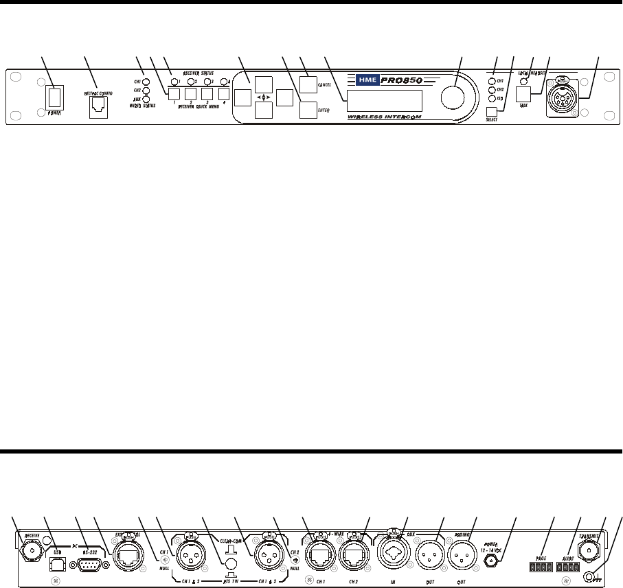
Base Station Front Panel Features
1. POWER switch
2. BELTPAC CONFIGuration connector
(RJ10 telephone handset cable connector)
3. WIRED STATUS lights
CH1 = Channel 1 intercom status
CH2 = Channel 2 intercom status
AUX = ISO+ mode
4. RECEIVER QUICK MENU buttons
5. RECEIVER STATUS lights
6. Arrow buttons (move curser around on menu)
7. ENTER button (selects function or setting)
8. CANCEL button (backs out of menus or
cancels operation)
9. Display screen
10. Multi-function knob (headset volume control;
adjustment for specific menu selections)
11. Local headset function lights
12. Local headset function select switch
13. Local headset TALK indicator light
14. Local headset TALK switch
15. Local headset connector
Base Station Rear Panel Features
1. Receiver antenna connector
2. USB type-B computer connector
3. 9-pin RS-232 computer connector
4. RS-422 interface
(for connecting two or more bases together)
5. Channel 1 null adjustment
6. Channel 1 2-wire intercom interface connector
7. ClearCom RTS select button
8. Channel 2 2-wire intercom interface connector
9. Channel 2 null adjustment
10. Channel 1 RJ45 4-wire intercom interface
connector
11. Channel 2 RJ45 4-wire intercom interface
connector
12. Auxiliary input connector
(accepts XLR plug or standard phone plug)
13. Auxiliary output connector
14. Paging output connector
15. 12-14VDC power jack
16. Page relay connector
17. Alert relay connector
18. Transmitter antenna connector
19. Grounding screw
1 2 3 4 5 6 7 8 9 10 11 12 13 14 15 16 17 18 19
3
1 2 3 4 5 6 7 8 9 10 11 12
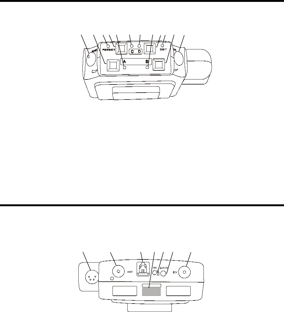
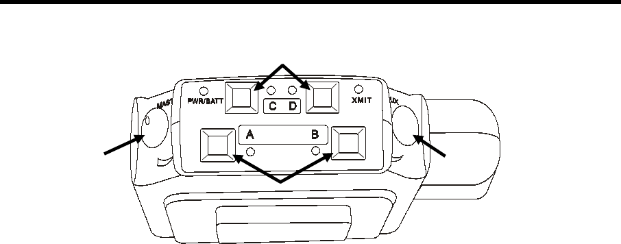
Beltpac Top Panel Features
1. Master power/volume control
2. “A” button
3. Power and battery condition indicator
4. “C” button
5. “A” light – indicates Channel 1 active
6. “C” function light
7. “D” function light
8. “B” light – indicates Channel 2 active
9. “D” button
10. Transmit light – indicates transmitter on
11. “B” button
12. Auxiliary volume control
Beltpac Bottom Panel Features
1. Headset connector
2. Transmitter antenna connector
3. Remote configuration connector
4. Battery compartment cover thumb grip
5. Microphone gain adjustment
6. Auxiliary input connector
7. Receiver antenna connector
1 2 3 4 5 6 7
4
BLOCK DIAGRAMS
Base Station
Beltpac

5
EQUIPMENT SPECIFICATIONS
Base Station
GENERAL ⎯
Frequency Range: 470-608 MHz, 614-740 MHz in 18 MHz TX and RX bands
Frequency Response: 50 Hz to 10 kHz
Power Requirements: 100-240VAC, 50-60Hz or 12-14VDC
Temperature Range: 0-50°C
Size: 19” x 1.72” x 11.5” (1-RU)
Weight: <11 lbs.
# of Receivers: 1 to 4, configurable
# of Transmitters: 0 to 2, configurable
4-Wire I/O: RJ45, 600Ω balanced, level adjustable, simultaneous operation with 2-wire
2-Wire I/O: XLR-3F, externally-switchable RTS® or ClearCom® mode, 200Ω,
level adjustable, null adjustable
Auxiliary Input: XLR-3F/¼” combo jack, 600Ω balanced, level adjustable
Auxiliary Output: XLR-3M, 600Ω balanced, level adjustable
Paging Output: XLR-3M, 600Ω balanced, level adjustable
Page & Alert Relay: 2 four-pin Molex, 60W switching capacity (2A @ 30VDC)
Beltpac Interface: RJ10, RS-232
PC Interface: DB9, RS-232, 38400 baud
USB Interface: USB 1.1 type B receptacle
External Control Interface: RJ45, RS-422
Headset Connector: XLR-4M, Optional field-installable XLR-5F
Mic Input: Auto-detect, low impedance dynamic or electret microphone
Headset Output: Stereo – 160mW per side
Mono – >200mW into 50Ω
Front Panel Controls: Power Switch
Up, Down, Left, Right, Enter & Cancel Menu Buttons
Receiver Quick-Menu Buttons
Rotary knob for adjustments
Headset channel select & PTT
Front Panel Indicators: Graphic LCD, 4 Receiver Status LEDs, 3 Intercom Status LEDs,
3 Headset channel select LEDs, Headset PTT LED
Rear Panel Controls: 2-wire channel line null
RTS®/ClearCom® mode switch
TRANSMITTER ⎯
Type: 720 synthesized, 25 kHz channel steps
Transmit Power: 240, 100, 10 or 1 mW
Modulation Type: FM
Deviation: 50 kHz
Occupied Bandwidth: 190 kHz maximum
Frequency Stability: 10 ppm
Harmonics/Spurious: Exceeds FCC specifications
Antenna Type: ¼-wave whip (supplied) or external (BNC connector)

6
RECEIVER ⎯
Type: 720 synthesized, 25 kHz channel steps
RF Sensitivity: <1µV for 20dB SINAD
Squelch: Adjustable
Image Rejection: 60dB
Squelch: Data channel coded plus carrier signal level
Squelch Quieting: 90dB
Frequency Stability: 10 ppm
Distortion: <1% at maximum deviation
Antenna Type: ¼-wave whip (supplied) or external (BNC connector)
Beltpac
GENERAL ⎯
Frequency Range: 470-608 MHz, 614-740 MHz in 18 MHz TX and RX bands
Antenna Type: Flexible ¼-wave, field-replaceable
Frequency Response: 50 Hz to 10 kHz
Battery Requirements: 6 “AA” Alkaline Cells (Optional NiMH)
Battery Life: PTE − Up to 9 hours (alkaline), PTT − Up to 15 hours (alkaline)
Temperature Range: 0-50°C
Weight: 16 oz with batteries
Base Interface: RJ10, RS-232
PDA Interface: IrDA
Auxiliary Input: Connector: 1/8” miniature phone jack
Impedance: 10kΩ
Receive Level: 100mV minimum
Overrides optional 2nd receiver if installed
Headset Connector: XLR-4M, Optional field-installable XLR-5F
Mic Input: Auto-detect, low impedance dynamic or electret microphone
Headset Output: 200mW @ 1% THD into 50Ω, capable of driving 8-400Ω
Controls: Main Volume Control with power switch and push-to-mute, 2nd RCVR/Ext.
Volume Control with push-to-mute, 4 mode/function switches
Microphone gain adjustment
Indicators: Power/low battery LED, Transmit LED, 2 channel LEDs, 2 function LEDs
TRANSMITTER ⎯
Type: Synthesized, 720 25 kHz channel steps
Transmit Power: 100, 50, 10 or 1 mW Configurable for fixed output or automatic power control
Transmission Modes: Push-to-talk (PTT), push-to-talk-shared (PTS), or push-to-enable (PTE)
May be configured for momentary or latch mode
Modulation Type: FM
Deviation: 50 kHz
Occupied Bandwidth: 190 kHz maximum
Frequency Stability: 10 ppm
Harmonics/Spurious: Exceeds FCC specifications
RECEIVER ⎯
Type: Synthesized, 720 25 kHz channel steps
RF Sensitivity: <1µV for 20dB SINAD
Image Rejection: 60dB
Squelch: Adjustable carrier signal level
Squelch Quieting: 80dB
Frequency Stability: 10 ppm
Distortion: <1% at maximum deviation
7
BASE STATION SETUP
Connect equipment and make adjustments described below to the rear panel of the base station where indicated
on this illustration.
1. RECEIVE Antenna Connector — Connect the receiver antenna to this BNC connector. The color band
(if present) around the antenna should match the color dot (if present) near the connector on the base.
2. USB Interface Connector — To interface the PRO850 with a PC using a computer interconnect cable
with a USB 1.1 compliant type-B connector, connect the cable from this connector to the PC.
3. RS-232 Interface Connector — To interface the PRO850 with a PC using a computer interconnect cable
with a 9-pin RS-232 serial interface connector, connect the cable from this connector to the PC.
4. Multiple Base Station Interface Connector — Use this RS-422 serial interface to connect master and
slave base stations together.
In the 2-Wire ISO+ mode, the headset connector on
the front panel of the base station is disabled from
normal headset functions and becomes available for
connection to devices other than a headset.
In the 2-Wire mode;
• If you have an RTS system, only one 2-wire cable
is needed for connecting bases. The switch on the
back panel of the base station must be set for RTS
TW. One cable carries both CH1 and CH2.
• If you have a ClearCom system, two cables are
needed for connecting base stations. The switch on
the back panel of the base station must be set for
CLEAR-COM.
In all multibase configurations, connect the Aux Out
from Slave 1 to the Aux In of the Master Base Station
and connect the Aux Out from Slave 2 (if present) to
the Aux In of Slave 1.
SECTION 2. EQUIPMENT SETUP
1 2 3 4 5 6 7 8 9 10 11 12 13 14 15 16 17 18 19
8
5. Channel 1 Line Nulling Control — Use this adjustment to null the Channel 1, 2-wire connection when
attached to other cabled intercom devices. This control is active even if the 4-wire only mode is selected.
6. Channel 1 2-Wire Intercom Connector — Provides 3-pin female XLR connector for interfacing other
cabled intercom devices to Channel 1 on the PRO850.
NOTE: PRO850 does not provide or require 2-wire line power.
RTS® Mode: Pin 1 = Common ClearCom® Mode: Pin 1 = Common
Pin 2 = Channel 1 Pin 2 = N/C
Pin 3 = Channel 2 Pin 3 = Channel 1
7. ClearCom®/RTS® Select Button — In position = RTS® Mode Out position = ClearCom® Mode
8. Channel 2 2-Wire Intercom Connector — Provides 3-pin female XLR connector for interfacing other
cabled intercom devices to Channel 2 on the PRO850.
NOTE: PRO850 does not provide or require 2-wire line power.
RTS® Mode: Pin 1 = Common ClearCom® Mode: Pin 1 = Common
Pin 2 = Channel 1 Pin 2 = N/C
Pin 3 = Channel 2 Pin 3 = Channel 2
9. Channel 2 Line Nulling Adjustment — Use this adjustment to null the Channel 2, 2-wire connection when
attached to other cabled intercom devices. This control is active even if the 4-wire only mode is selected.
10. Channel 1 RJ45 4-wire Intercom Interface Connector — Use this
RJ45 connector for 600Ω balanced interface of PRO850 Channel 1 with
other cabled intercoms. Pin designations are as follows.
Pins 1, 2, 7 & 8 have no connection
Pin 3 = Intercom Out +
Pin 4 = Intercom In +
Pin 5 = Intercom In –
Pin 6 = Intercom Out –
11. Channel 2 RJ45 4-wire Intercom Interface Connector — Same as #10, but for Channel 2.
12. Auxiliary Input Connector — Use this 3-pin female XLR/standard-phone-jack connector for balanced
+20dBV maximum auxiliary audio input. Pin 1 = Ground
Pin 2 = Audio +
Pin 3 = Audio –
13. Auxiliary Output Connector — Use this 3-pin male XLR connector for balanced +20dBV maximum
auxiliary audio output. Pin 1 = Ground
Pin 2 = Audio +
Pin 3 = Audio –
14. Paging Output Connector — Use this 3-pin male XLR connector for balanced +20dBV maximum paging
audio output. Pin 1 = Ground
Pin 2 = Audio +
Pin 3 = Audio –
15. 12-14VDC Power Jack — Use this connector for DC power input.
16. Page Relay Connector — Use this 4-pin Molex connector for relay closure based on beltpac page
control. Switching capacity of the relay is 60W (2A @ 30VDC). Pin designations are as follows.
Pin 1 = Common
Pin 2 = Normally Closed
Pin 3 = Normally Open
Pin 4 = Ground
17. Alert Relay Connector — Use this 4-pin Molex connector for relay closure based on alert conditions.
Switching capacity of the relay is 60W (2A @ 30VDC). Pin designations are the same as for #16 above.
18. TRANSMIT Antenna Connector — Connect the transmitter antenna to this BNC connector. The color
band (if present) around the antenna should match the color dot (if present) near the connector on the base.
19. Grounding Screw — If necessary, tie this connector to earth ground.
Pin 1
9
BASE STATION OPERATION
Uses of Front Panel Controls, Indicators and Connectors
1. Power Switch
Press the upper part of the switch to turn the power on. A red light on the switch will be lit when the base
station power is on. Press the lower part of the switch to turn the power off. The red light will go off.
2. Beltpac Configuration Connector
After beltpac configuration settings have been made in the base station, plug one end of the enclosed RJ10
interconnect cable into this connector, and plug the other end into the RMT receptacle on the bottom of a
beltpac to upload the settings into the beltpac. Repeat this to upload settings for each beltpac to be used.
CAUTION: Be sure not to turn the beltpac power off and on again while it is connected to the base
station. If this does happen, unplug the cable and cycle the beltpac power again.
3. Wired Status Indicator Lights
CH1 and CH2 lights:
If a 4-wire intercom channel is enabled, the respective CH1/CH2 light will blink when the PRO850 is
sending audio on that intercom line.
If a 2-wire interface channel is enabled, the respective CH1/CH2 light will be on steady when the user
is not talking. When the user is talking, the light will be on steady and blinking off.
AUX light:
The auxiliary light indicates use of the ISO+ mode. When ISO+ is on, the AUX light will be on
steady. When someone is talking on the ISO channel, the light will be on steady and blinking off.
4. Receiver Status Indicators and Buttons
RECEIVER STATUS lights 1 – 4:
Steady red if the respective receiver squelch is turned down, or if it is receiving a signal (squelch is open).
Blinking amber when the respective receiver is receiving status update from a beltpac.
Steady green when the beltpac user is talking through the receiver.
Blinking red or green if the beltpac being received has a low battery condition.
RECEIVER QUICK MENU buttons 1 – 4:
When pressed, squelch and audio controls for the respective receiver are provided immediately on the
display screen.
5. Local Headset Connector and Controls
Plug your local headset connector into the receptacle at the right end of the PRO850 front panel.
Use the SELECT button to choose communication channels CH1, CH2, CH1 and CH2 together, or ISO.
The respective indicator light above the button will remain lit for the selection you make.
Press and release the TALK button quickly to “latch on” for open communication. Press and release the
button again quickly to “latch off.”
Press and hold the TALK button for more than one second for momentary communication. In this mode,
the selected channel will remain open only as long as you are pressing the TALK button.
SECTION 3. PRO850 OPERATION
1 2 3 4 5
10
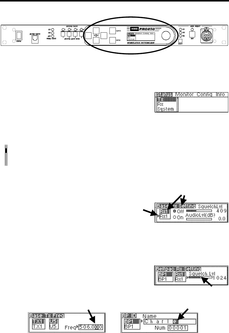
Display Screen Navigation
To navigate through PRO850 screen displays, use the W XST, ENTER and CANCEL buttons and the control
knob adjacent to the screen as follows.
W X Use the left and right arrow buttons to move through horizontal
selections on the bar at the top of the main menu, and to move
to the left and right on advanced screens.
ST Use the up and down arrow buttons to move through vertical
selections on the main menu, such as Tx, Rx and System,
and to move up and down on the screen.
The bar next to vertical selections has an indicator in it that moves up or down as you use the up and
down arrow buttons to move through selections. The indicator will move up and down the bar in
increments, from the top of the bar for the first selection to the bottom of the bar for the last selection.
NOTE: Holding an arrow button continuously will allow you to move rapidly through selections.
ST When a curser appears on the screen, use any of the four
W X arrow buttons to move it around to desired selectable items,
or to change the content of a box adjacent to the curser.
Use the ENTER button to make a selection indicated by a curser or highlighted button (e.g. Off/On), or to
advance to the next screen from a highlighted selection.
Use the CANCEL button to move back to a previous screen. Press CANCEL repeatedly to return to the main menu.
Use the control knob to adjust values selected with the curser
such as frequencies, squelch levels and auxiliary output mix levels.
Use the control knob together with the up and down arrow buttons to change numbers such as frequency
numbers, or words such as beltpac user names in selected boxes. The arrow buttons move highlighted numbers
left and right, while the control knob changes the numbers, letters or symbols.
Main Menu
Currently selected items
are highlighted.
11
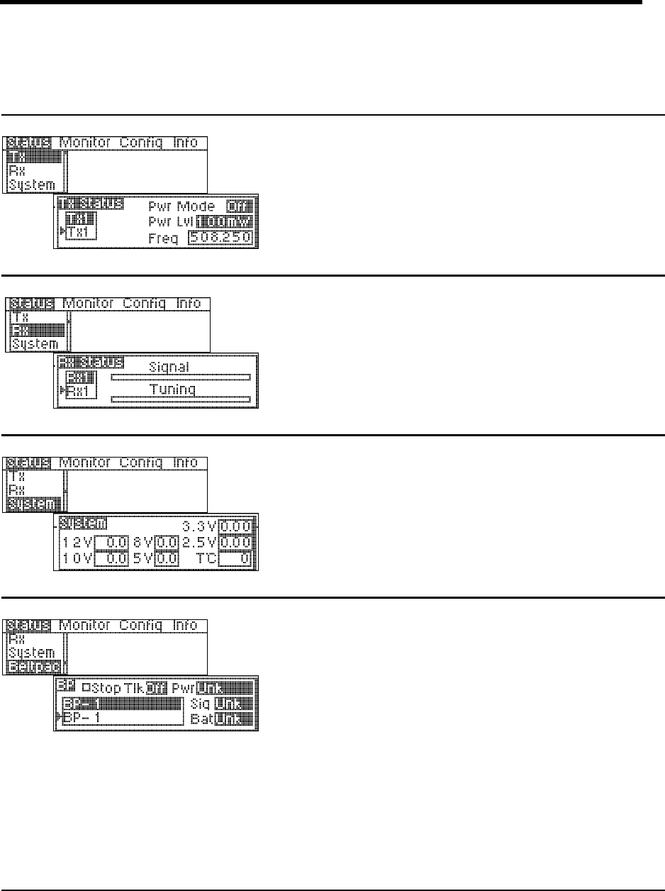
Display Screen Functions and System Settings
Status displays provide information indicating the status of the system, or of parts or functions of the system.
Transmitter Status:
Select transmitter 1 or 2, then press the ENTER
button to obtain the status of the selected
transmitter.
Receiver Status:
Select receiver 1 through 4, then press the
ENTER button to observe signal and tuning
levels at the selected receiver.
System Status:
Base station power supply voltages are shown.
The 12V box shows the actual input voltage
supplied to the base station. The T°C box shows
base station internal temperature in degrees Celsius.
Beltpac Status:
Select a beltpac by the name or number shown,
then press the ENTER button to obtain its status.
Select Stop Tlk to stop a latched-on beltpac from
transmitting.
The Pwr box shows the current transmitter power
level of the selected beltpac.
The Sig box indicates how well the beltpac is
receiving transmission (Low, OK or High) from
the base station.
The Bat box shows battery status of the selected
beltpac (OK, Low or Dead).
NOTE: In Push-To-Talk (PTT) or Push-To-Enable
(PTE) modes, beltpacs automatically update status to
the base station every 5 seconds. In Push-To-Share
(PTS) mode, beltpacs only update status while they
are transmitting. If no transmission is received from a
beltpac within 20 seconds, its status will be shown as
Unk (unknown). Also, if a beltpac is out of range, or
its power is off, its status will be shown as Unk.
12
Talk Status:
Beltpac user identification is shown when beltpac
user is pressing Talk button.
Monitor displays provide input/output levels and input level adjustments for all devices connected to the base station.
Monitors Audio Levels at Base Station Inputs:
Select the desired input source, then move the
curser to the bar at the top of the screen. Use the
control knob to adjust the audio input level from
the selected source in 1.5dB increments.
Monitors Audio Levels at Base Station Outputs:
Use the up/down arrow button to view the output
level from the DSP of the desired output to be
monitored.
13
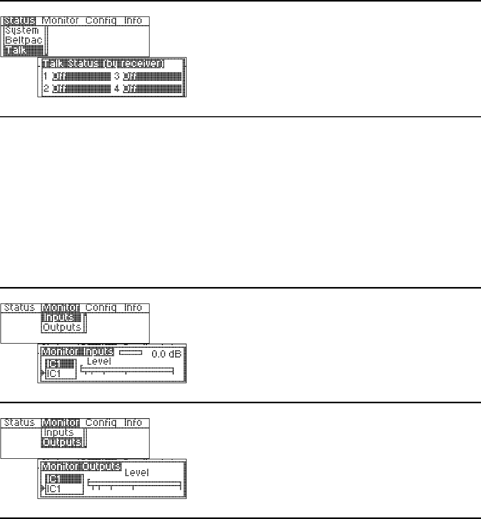
Configuration displays provide customized configuration settings for the base station and beltpacs. They also
allow you to save your settings to a file for future access. Advanced settings are provided for output mixing, alert
signals and paging capabilities. Beltpac ID name and number settings made at the main base station can be
synchronized in added slave base stations via the Configuration, Sync Bases display.
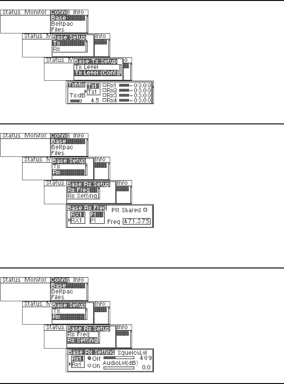
Base Station Transmitter Power:
Select transmitter 1 or 2, then press the ENTER
button.
At the power level box, select 1, 10, 100 or
250mW, then press ENTER. To change the
Off/On status of the transmitter, select the Off or
On button, then press ENTER.
Base Station Transmitter Frequency:
Frequencies P1 – P4, S1 – S4 and T1 – T4 are
preset in the system and cannot be changed.
Frequencies U1 – U5 can be set by the user.
Select transmitter TX1 or TX2, then select a
frequency for that transmitter. If you select a user
frequency, U1 – U5, move the cursor to the
frequency box and use the up and down arrow
buttons together with the control knob to select a
frequency. User frequencies can be selected in
25kHz increments.
NOTE: Frequencies within the same group
(P, S or T) are compatible with each other and free
of intermodulation.
Base Station Transmitter Mix Levels:
Select transmitter 1 or 2, then press the ENTER
button.
Use the left arrow button to select the Tx box,
then use the control knob to adjust the transmitter
master level in 1.5dB increments.
Select the box next to IC1, IC2 and Aux to enable
that input in the output mix. Mic is a standard
output.
Place the cursor to the left of any slider bar and use
the control knob to adjust each output level in
increments of .25dB (fine) or 2.25dB (coarse).
14
Base Station Transmitter Mix Levels (continued):
Select transmitter 1 or 2, then press the ENTER
button.
Use the left arrow button to select the Tx:dB box,
then use the control knob to adjust the transmitter
output level in 1.5dB increments.
Select the box to the left of RX1 through RX4, to
continuously enable a particular receiver to the
transmitter. NOTE: Leave these boxes
unchecked for normal operation.
Place the cursor to the left of any slider box and use
the control knob to adjust each output level in
increments of .25dB (fine) or 2.25dB (coarse).
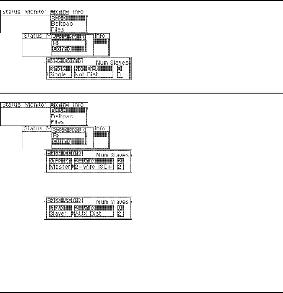
Base Station Receiver Frequency:
Frequencies P1 – P4, S1 – S4 and T1 – T4 are
preset in the system and cannot be changed.
Frequencies U1 – U5 can be set by the user.
Select receiver RX1 or RX2, then select a
frequency for that receiver. If you select a user
frequency, U1 – U5, move the cursor to the
frequency box and use the up and down arrow
buttons together with the control knob to select a
frequency. User frequencies can be selected in
25kHz increments.
For multiple beltpacs to share a receiver frequency
(PTS), check the Ptt Shared box.
NOTE: Frequencies within the same group
(P, S or T) are compatible with each other and free
of intermodulation.
Base Station Receiver Control:
Select a receiver and select the Off or On button
to turn it off or on. Use the up and down arrow
buttons together with the control knob to adjust
the squelch and audio levels.
NOTE: The amount of gain applied here to
receiver audio level at input of DSP will also be
shown on the Monitor Input display screen for that
receiver.
15
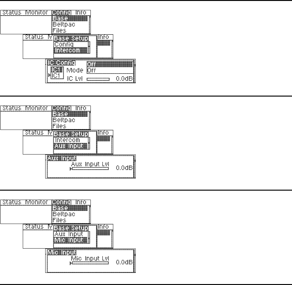
Single Base Station Configuration:
Select Single, Not Dist for a single base station
without the ISO+ feature for communication only
among beltpacs.
Select Single, ISO+ for a single base station with
the ISO+ feature for communication among
beltpacs and auxiliary input and output
(Aux In/Out) connections.
Master / Slave Base Station Configuration:
If Master and Slave base stations will be used,
there can only be one master base station, with
one or two slaves. Select Master, Slave 1 or Slave
2, then select the multibase wiring configuration;
2-Wire, 2-Wire ISO+ or Aux Dist.
Master:
In the 2-Wire ISO+ mode, beltpacs having a
button configured for Talk Aux must transmit
on frequencies for the master base station for
the feature to work.
Slaves:
In the Aux Dist mode, beltpacs on slave base
stations can only talk on the same channel at
once. If they try to talk on a different channel
than the user already talking, they will hear a
busy signal in their beltpac headset.
A slave cannot have slaves. Therefore, when
Slave 1 or 2 is selected, the Num Slaves
(number of slaves) will automatically be 0.
If a slave base station has a transmitter
installed, it must be turned off. See Base TX
setup.
16
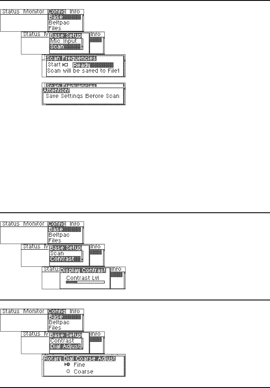
Base Station Intercom Configuration:
Select intercom IC1 or IC2, then use the up and
down buttons to select what mode the intercom is in.
Select the IC Lvl box, and use the control knob to
adjust the input gain level.
NOTE: If the Mode is set to Off, the input and
output of that intercom will be off. If set for
2-wire, both 2 and 4-wire will be active. If set for
4-wire, only 4-wire interface will be active.
Base Station Auxiliary Input Level:
Use the control knob to adjust the auxiliary input
level. Any change made here will be reflected in
the Monitor Input display for Aux Input.
Base Station Microphone Input Level:
Use the control knob to adjust the front-panel
headset microphone input level. Any change
made here will be reflected in the Monitor Input
display for the Mic Input.
17
Frequency Scan:
Connect a beltpac to the BELTPAC CONFIG
connector on the front panel of the base station to
enable scanning of base transmit frequencies.
In this operation, the beltpac and base station
receivers are scanned to find the cleanest group of
frequencies for the base station to transmit on, and
they are assigned to TX1 and TX2 in the base
station. Also, based on the number of receivers in
the system (up to 12), it determines the best group
of frequencies for the base station(s) to receive on.
Those frequencies are distributed (first-come,
first-served) to the beltpacs (with the assumption
that 16 beltpacs will be used) as beltpac transmit
frequencies. Beltpac receiver frequencies are
always the same as the base station TX1 and TX2
frequencies.
Beltpac frequency settings will not be operational
until they are uploaded to the beltpacs, which
should be done after completion of beltpac
configuration settings.
These settings will automatically be saved to File 1
as active settings for the base station until the
frequencies are scanned again. They can also be
saved to another file name for future use.
To begin frequency scanning, press the ENTER
button.
Base Station Display Contrast Level:
Use the control knob to adjust the base station
display screen contrast level.
Base Station Dial Adjustment Setting:
Select Fine or Coarse for the control knob, for mix
level dial adjustments. In the Fine mode, mix
level adjustments made by the control knob occur
in 0.25dB increments. In the Coarse mode, they
occur in 2.25dB increments.
18
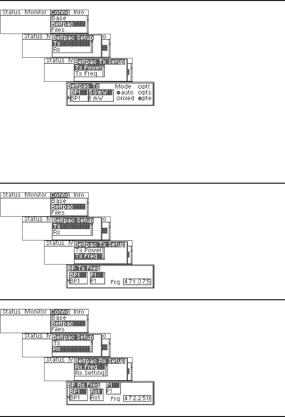
Beltpac Transmitter Power:
Select the desired beltpac and its transmitter
power level (1, 10, 50 or 100mW).
Select the transmit mode and press the ENTER
button.
NOTE: Settings for beltpacs B1-B16 are stored
in the base station. Changes to beltpac settings
will not be effective until they are uploaded to the
beltpacs. BPCN is the beltpac that is plugged into
the base station, therefore changes to its settings
are effective immediately.
In the auto mode, transmitter power will be
automatically controlled by the base station,
changing between 1 and the specified maximum.
In the fixed mode, the setting you select will not
change.
If you select ptt, the beltpac transmitter will be on
briefly every 5 seconds to transmit status. If you
select pts, the beltpac will only transmit while a
user is talking. If you select pte, the beltpac will
transmit constantly.
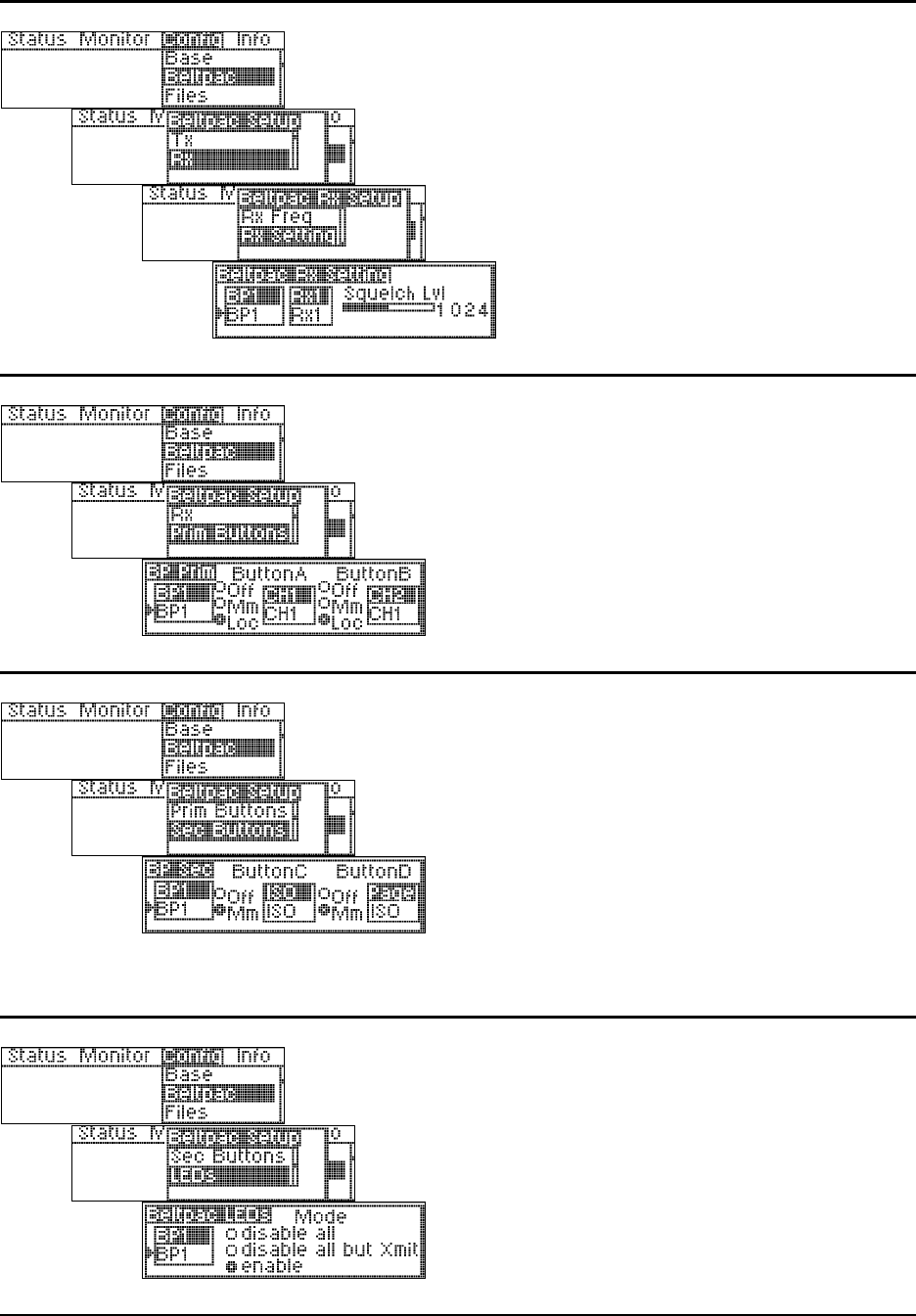
Beltpac Transmitter Frequency:
Select the desired beltpac and the transmitter
frequency for that beltpac’s operation (P1-12, S1-
12, T1-12 and U1-16. If U1-16 is selected, use
the control knob and the up and down arrow
buttons to select the desired frequency, in 25kHz
increments.
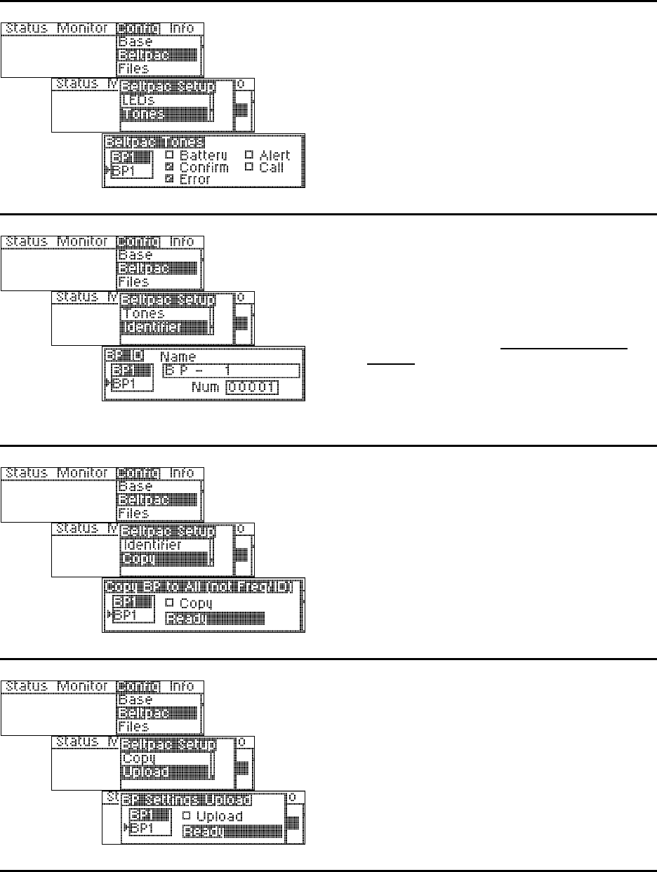
Beltpac Receiver Frequency:
Select the desired beltpac and the receiver
frequency for that beltpac’s operation (P1-4, S1-4,
T1-4 and U1-16. If U1-16 is selected, use the
control knob and the up and down arrow buttons to
select the desired frequency, in 25kHz increments.
NOTE: RX1 is for intercom CH1. RX2 is for
intercom CH2. Normally beltpac RX1 is the same
as base station TX1, and beltpac RX2 is the same
as base station TX2.
19
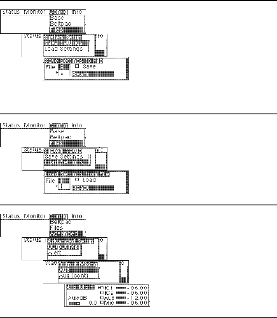
Beltpac Receiver Squelch Level:
Select the beltpac and receiver, then use the
control knob to adjust its squelch level.
NOTE: RX2 is reserved for a second receiver,
when a beltpac has two receivers.
BPCN is the beltpac that is plugged into the base
station, therefore adjustments to its squelch level
are effective immediately.
Beltpac Buttons A and B Setup:
Select the beltpac and select the desired functions
for Button A and Button B on each beltpac.
CH1 = Talk, Channel 1
CH2 = Talk, Channel 2
Curr = Talk, Current Channel
ISO = Talk, ISO/ISO+
Page = Talk, Page (Stage announce)
Aux = Talk, Auxiliary Out
Beltpac Buttons C and D Setup:
Select the beltpac and select the desired functions
for Button C and Button D on each beltpac.
ISO = Talk, ISO/ISO+
Page = Talk, Page (Stage announce)
Aux = Talk, Auxiliary Out
Chan = Toggle CH1/CH2
Call = Call Signal
Alert = Alert Signal
NOTE: Call and Alert Signals only function
while the Talk function is active.
Beltpac LED settings:
Select the beltpac and select the desired functions
the LEDs on each beltpac.
20
Beltpac tone settings:
Select a beltpac, then select the events for which
you would like tones to sound in that beltpac
user’s headset.
Beltpac user identifier settings:
To assign identification to a beltpac, such as a
user’s name, select a beltpac then use the arrow
buttons and selector knob to assign a name and
number to each beltpac.
NOTE: Each beltpac must have a different
number, and each assigned number must be
programmed into the base, or the base will not
recognize the beltpac.
Names can also be used if desired.
Copy Beltpac Settings:
To copy settings from one beltpac to all others for
all settings except ID numbers, names and
frequencies, select Copy and press the ENTER
button.
Upload Beltpac Settings:
To upload all beltpac settings from the base
station to a beltpac, select a beltpac then select the
upload box and press the ENTER button.
NOTE: A beltpac must be connected to the
BELTPAC CONFIG connector on the front panel
of the base station to enable uploading of beltpac
settings.
21
Save Configuration Settings to File:
To save your configuration settings to a file, select
the File number then select Save and press the
ENTER button.
NOTE: File number 1 is reserved for frequency
scans. Files can be saved to 2 through 10.
Be sure to save any changes before turning a base
station off. Files are not automatically saved
when the power is turned off.
The last file used before a base station is turned
off will be used the next time the base station is
turned on.
Load Configuration Settings from File:
To load configuration settings from a previously
saved file, select the File number then select
Load. When the settings have been successfully
loaded, Ready will be replaced by Busy, then
Success.
After loading settings, that file becomes the
current file and will be used again if the power is
turned off.
Auxiliary Output Mixing:
Select the box next to IC1, IC2, Aux and/or Mic to
enable input, then use the control knob to adjust
output level in 0.25dB or 2.25dB increments for
the desired mix.
Place the cursor to the left of the bar below Aux:dB
and use the control knob to adjust the overall Aux
audio output level in 1.5dB increments.
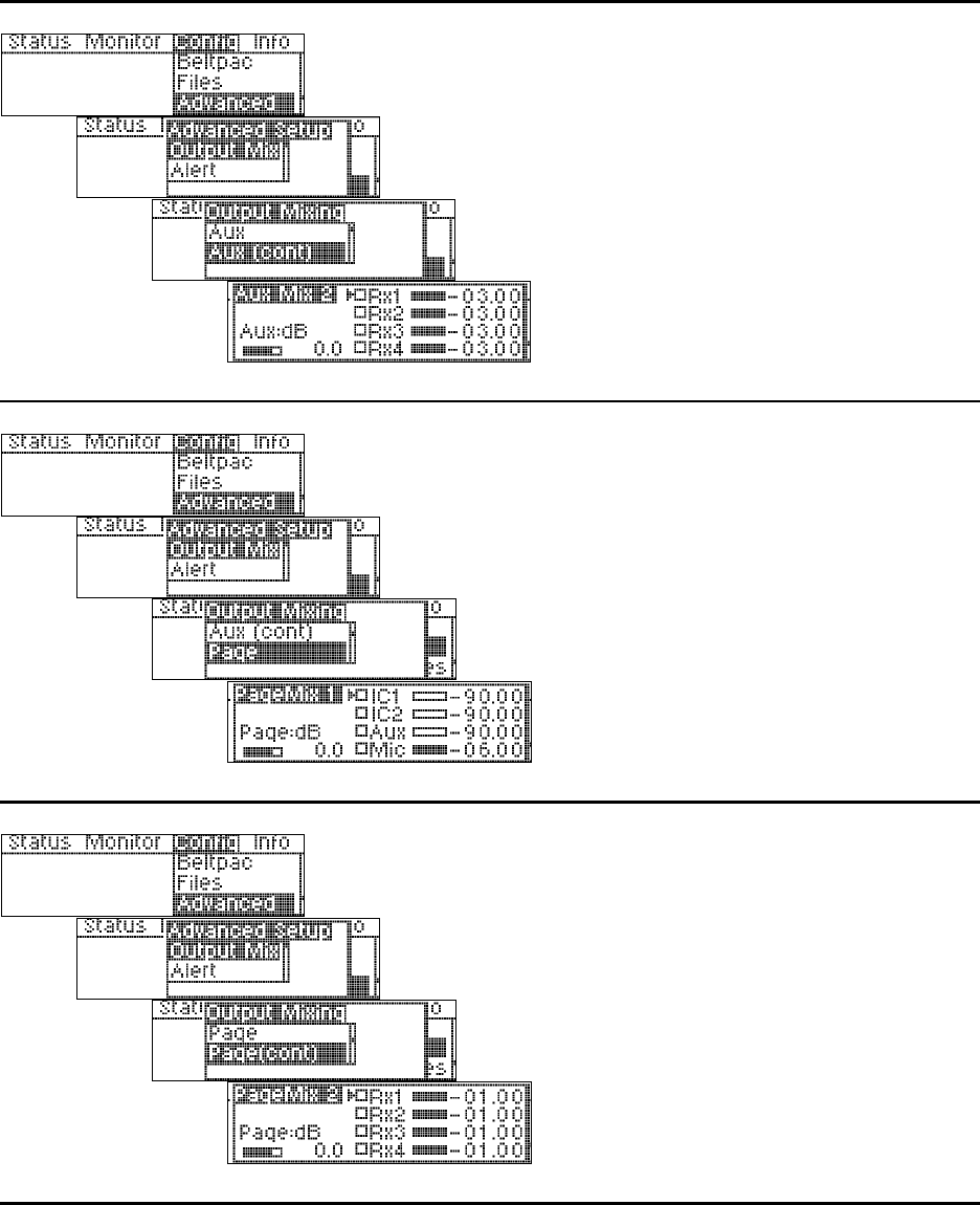
22
Auxiliary Output Mixing (continued):
Select the box(es) next to RX1-RX4, then use the
control knob to adjust output level in 0.25dB or
2.25dB increments for the desired mix.
Check these boxes only if you want receiver audio
continuously fed to the Aux Output. Leave them
unchecked for normal operation.
Place the cursor to the left of the bar below Aux:dB
and use the control knob to adjust the overall Aux
audio output level in 1.5dB increments.
Page Output Mixing:
Select the box next to IC1, IC2, Aux and/or Mic to
enable input, then use the control knob to adjust
output level in 0.25dB or 2.25dB increments for
the desired mix.
Place the cursor to the left of the bar below Page:dB
and use the control knob to adjust the overall Page
audio output level in 1.5dB increments.
Page Output Mixing (continued):
Select the box(es) next to RX1-RX4, then use the
control knob to adjust output level in 0.25dB or
2.25dB increments for the desired mix.
Check these boxes only if you want receiver audio
continuously fed to the Page Output. Leave them
unchecked for normal operation.
Place the cursor to the left of the bar below Page:dB
and use the control knob to adjust the overall Page
audio output level in 1.5dB increments.
23
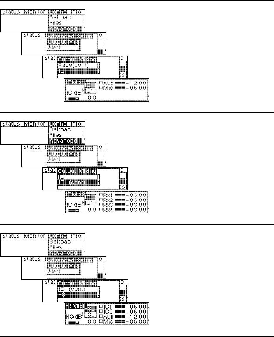
Intercom Output Mixing:
Select IC1 or IC2, then select the box next to Aux
and/or Mic to enable input. Use the control knob
to adjust output level in 0.25dB or 2.25dB
increments for the desired mix.
Place the cursor to the left of the bar below IC:dB
and use the control knob to adjust the overall IC
audio output level in 1.5dB increments.
Intercom Output Mixing (continued):
Select IC1 or IC2, then select the box(es) next to
RX1-RX4 to enable input. Use the control knob
to adjust output level in 0.25dB or 2.25dB
increments for the desired mix.
Check these boxes only if you want receiver audio
continuously fed to the Intercom Output. Leave
them unchecked for normal operation.
Place the cursor to the left of the bar below IC:dB
and use the control knob to adjust the overall IC
audio output level in 1.5dB increments.
Headset Output Mixing:
Select HSL (headset left) or HSR (headset right),
then select the box next to IC1, IC2, Aux and/or
Mic to enable input. Use the control knob to
adjust output level in 0.25dB or 2.25dB
increments for the desired mix.
Place the cursor to the left of the bar below HS:dB
and use the control knob to adjust the overall
headset audio output level in 1.5dB increments.
24
Headset Output Mixing (continued):
Select HSL (headset left) or HSR (headset right),
then select the box(es) next to RX1-RX4 to enable
input. Use the control knob to adjust output level in
0.25dB or 2.25dB increments for the desired mix.
Check these boxes only if you want receiver audio
continuously fed to the Headset Output. Leave
them unchecked for normal operation.
Place the cursor to the left of the bar below HS:dB
and use the control knob to adjust the overall
headset audio output level in 1.5dB increments.
Alert Settings:
To set the Alert relay to close under the desired
conditions select any or all of the boxes by
moving the cursor to a box and pressing the
ENTER button. If no boxes are checked, the alert
relay will not be used.
NOTE: Error indicates the base station detects
an error condition. Over Temp indicates the
internal base station temperature is excessive.
BP Low Battery indicates that any beltpac in the
system has a low battery. BP Button indicates
any beltpac button that has been programmed as
an alert button.
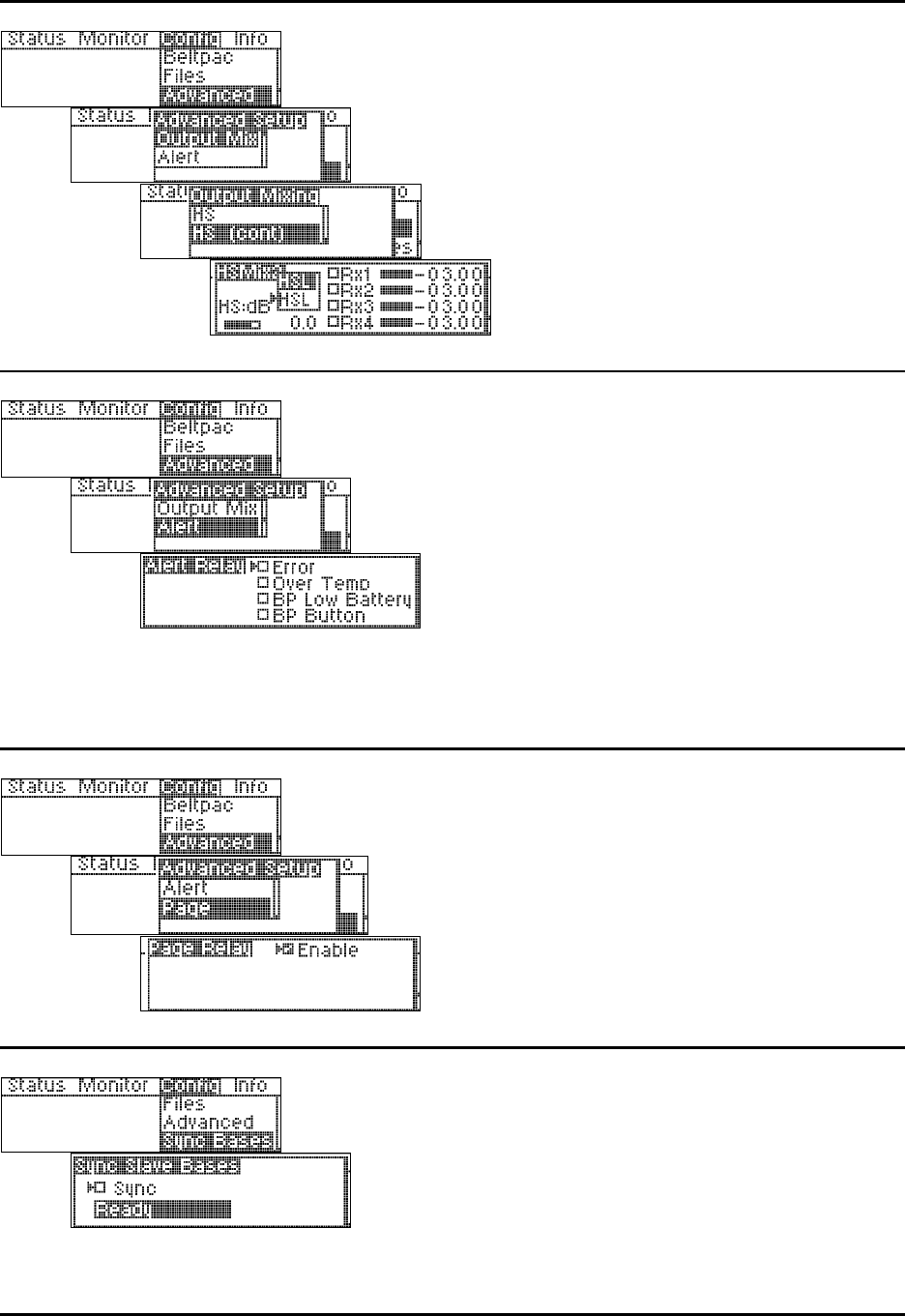
Page Settings:
To activate the page feature, select Enable and
press the ENTER button.
NOTE: If the page relay is not enabled and a
beltpac page button is pushed, a reject tone will be
heard in the beltpac’s headset.
Synchronize Base Station Settings:
To configure synchronized base station settings,
press the ENTER button.
NOTE: This only pertains to systems with master
and slave base stations. All beltpac settings are
done in the master base station. Synchronizing
the slave bases will cause all settings from the
master base station to be transferred to the slaves.
25
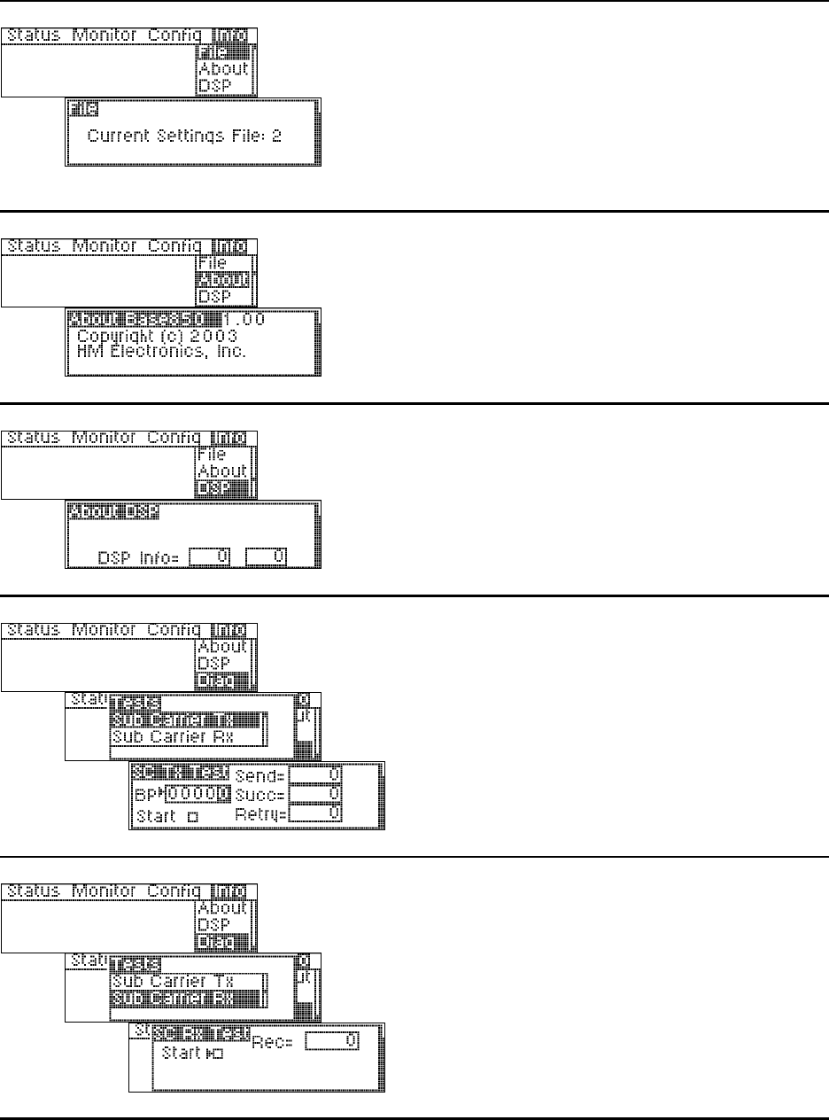
Information displays provide information about the base station and its current configuration settings file, and
testing capability for transmitter and receiver sub carriers.
The file number displayed is for current
configuration settings. It was the settings file
being used the last time the base station was
turned off, or the last settings file you saved since
the base station was turned on.
This is the file that will be used next time the base
station power is turned on.
Base station software version number and date
are displayed.
DSP software version number is displayed.
To perform a sub carrier transmitter test, with
the curser at the BP box, enter a beltpac ID
number then select Start. Let the test run for a
few seconds then press the ENTER button to stop
it. The results will be shown at the right side of
the display.
NOTE: The beltpac must be turned on and set to
the PTT or PTE transmit mode.
Press the beltpac C and D buttons on a beltpac
simultaneously. To perform a sub carrier
receiver test, select Start then press the ENTER
button.
26
1
BELTPAC OPERATION
Controls and Buttons
1. Master On/Off Volume Control
Turns beltpac on and off.
Controls volume levels and beep intensity.
Press and hold control button in to mute primary receiver input.
2. A and B Buttons
Perform functions set up in beltpac programming. Refer to Equipment Setup in Section 2.
If set up for Lock function, press and release button in less than one second to lock on.
Press and hold for momentary function, to remain on only while button is held.
If set up for Momentary function, button will remain on only while held. Lock feature cannot be used.
Either or both of these buttons can be turned off in beltpac setup.
3. C and D Buttons
Perform functions set up in beltpac programming. Refer to Equipment Setup in Section 2.
Only momentary function can be used. If set for momentary function, button will remain on only while
held. C and D buttons have no lock function.
Either or both of these buttons can be turned off in beltpac setup.
4. Auxiliary Volume Control
Controls mix levels of auxiliary input or an optional second receiver.
Press and hold control button in to mute auxiliary input or second receiver.
1
2
3
4
27
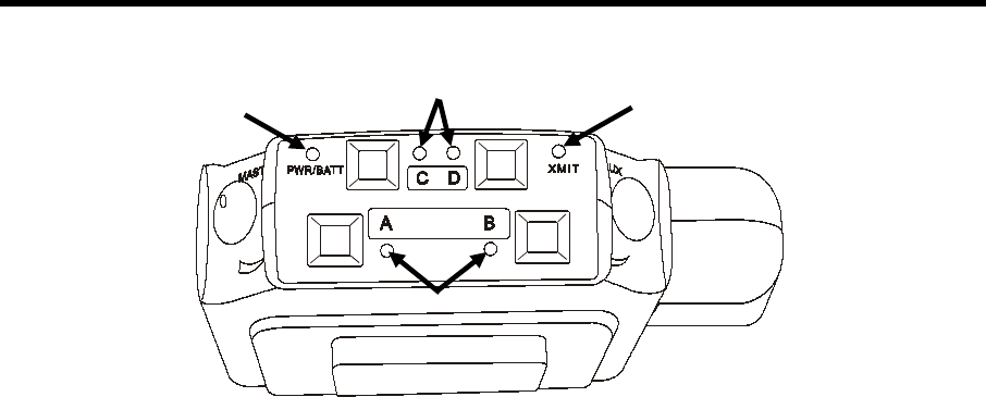
Indicator Lights
1. Power/Battery Light
Remains lit when power is on. Green = good batteries
Amber = low batteries
Red = nearly dead batteries
2. C and D Lights
On while any functions programmed into C and D buttons are activated.
3. Transmit Light
On steady red while beltpac is transmitting.
4. A and B Channel Indicator Lights
A-green while listening on Channel 1. B-green while listening on Channel 2.
A-red while talking on Channel 1. B-red while talking on Channel 2.
If indicator lights (LEDs) are configured on, holding the C and D buttons while turning the beltpac power on
will disable them until the next time the beltpac is turned off and on again.
If LEDs are configured off, holding the C and D buttons while turning the beltpac power on will turn the LEDs
back on until the next time the beltpac is turned off and on again.
If LEDs are configured off, when normally turning the beltpac power on, all LEDs will blink on momentarily.
1 3
4
2
28
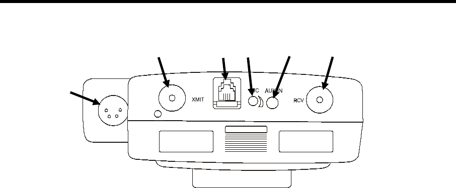
Connectors and Adjustment
1. Headset Connector
XLR type connector.
2. Antenna Connectors
Transmitter antenna connector has color dot (or none), matching color band (or none) on transmitter antenna.
Receiver antenna connector has color dot (or none), matching color band (or none) on receiver antenna.
Screw antennas securely into connectors.
3. RMT Connector
Used for interconnect cable to base station, for uploading beltpac configuration settings and frequency scans.
CAUTION: Beltpac should not be turned off and back on while connected to base station or controller
malfunction may occur. If this happens, unplug the connector, turn the baltpac power off, wait at least one
second and turn the power back on. An ordinary telephone handset cable may be used to connect the
beltpac to the base station.
Interconnect cable has RJ-10 type connectors.
4. Headset Microphone Gain Adjustment
Adjusts headset microphone gain ±10dB.
NOTE: Beltpac automatically detects electret or dynamic microphone.
5. Auxiliary Input Connector
1/8 inch jack receptacle for line level monaural audio source.
If the beltpac includes a second (optional) receiver, plugging into this location will disconnect the second
receiver and connect the auxiliary input device in its place.
1
2 3 4 5 2
29
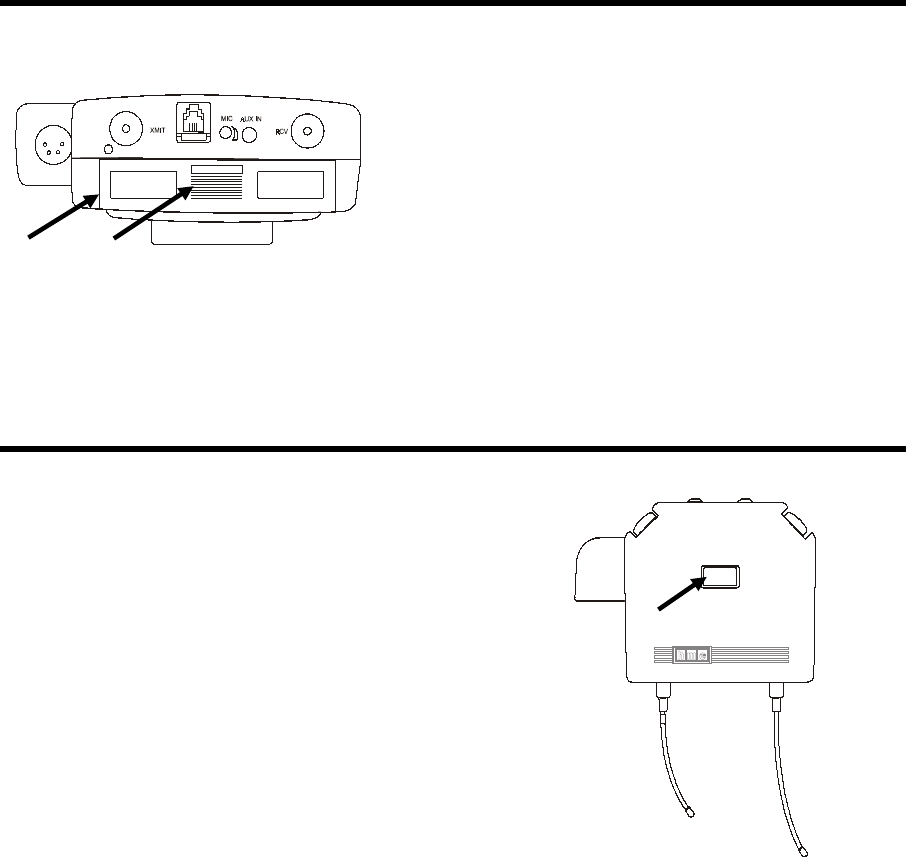
Batteries
1. Battery Compartment Cover
2. Battery Cover Release Grid
To change batteries:
Place your thumb on the battery cover release grid
and pull back on the battery compartment cover to
open the battery compartment. Carefully flip the
cover up and slide it to the back of the opening and
push it slightly downward to release the battery
sled into your hand.
Remove the six 1.5V AA batteries from the sled
and replace them with six fresh ones.
Carefully slide the battery compartment cover back
over the compartment until its latches securely in
place.
Infrared Window
The infrared window provides capability for interfacing
with a PDA for easy PRO850
configuration setups.
Optional HME PDA850 software is required.
1 2

30
PC850 is a Microsoft Windows® application which enables the user to make all PRO850 base station and
beltpac configuration settings on a PC and save the settings to files. An RS-232 interface cable must be used to
connect the PRO850 base station to the PC in which PC850 software is installed.
PC850 Installation
NOTE: Before installing PC850, close all other programs that are open.
To install PC850 under WindowsJ 95, WindowsJ 98, WindowsJ NT4.0 Svc Pac 3, WindowsJ 2000,
WindowsJ ME or WindowsTM XP, follow the instructions below.
1. Insert the CD into a selected CD-ROM drive.
• If the CD-ROM drive is set for AutoPlay, the PC850 installation will begin automatically.
Skip steps 2 and 3.
• If the CD-ROM drive is not set for AutoPlay, continue with steps 2 and 3 below.
2. Under Windows Explorer or File Manager, double click on the CD-ROM drive where the CD is inserted.
3. Double click on the setup.exe file, and the PC850 installation will begin.
Proceed as instructed on the installation screens. When the installation has been completed, select Finish to end
the installation process.
SECTION 4. PC850 SOFTWARE
Minimum Requirements for Use of PC850 Software
• IBM compatible PC with a PentiumTM microprocessor
• Minimum of 32 megabytes RAM
• Minimum of 100 megabytes available hard disk space
• One available RS-232 serial port or a modem interface
• Serial interface cable appropriate for your PC (See Section 2.1)
• Microsoft WindowsTM 95, WindowsTM 98, WindowsTM NT4.0 Svc Pac,
WindowsTM 2000, WindowsTM ME or WindowsTM XP
• Familiarity with WindowsTM operating system
• Internet Explorer 4.1 or later
To install PC850 for Windows NT/2000, you must be a System Administrator. For Windows NT/2000,
if you have installed this product for multiple users, you may give authorization to all PC850 users at
once. To do this, log into the computer as System Administrator and install PC850 according to these
instructions. After successful installation, all users will have access to PC850. To be able to run PC850,
each user must have “Read, Write and Execute” permission for the ProgramFiles\HME\PC850 directory.
31
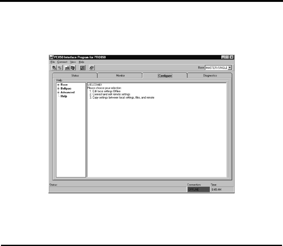
PC850 Operation
To open the PC850 software, double click on the PC850 icon on your desktop screen.
When the PC850 opens, the screen below will appear on your PC.
Select the Status, Monitor, Configuration or Information tab with your cursor. The respective screen will
appear with all the same functions and system settings that are available on the PRO850 base station. Place
your cursor over the desired setting on the screen and a drop-down menu will appear with the applicable
selections or information.
PC850 can be operated in either of two modes: Offline or Online. Offline means that the program is operated
without any connection to a PRO850 base station. In this mode, the only screens that can be accessed are under
the Configuration tab. This allows a user to set up configurations and save them to disk so that they can be
loaded into the base station later. While offline, the connection status indicator on the status bar at the bottom of
the window will be red. Online means that the base station is connected to the PC and that a logical connection
between the two has been established.
To switch to online mode, first be sure that an appropriate cable is connected between the base station and the
PC. Then select Connect from the Connect menu or press the Connect button on the toolbar. This will open the
Connect to System dialog box. There, choose the appropriate connection and click Connect. Once online, the
connection status indicator will be green.
The first three tabs on the PC850 window match the first three menus on the BS850 LCD screen: Status,
Monitor, and Configure. The fourth tab, Diagnostics, matches the base station diagnostics menu item under the
Info menu. The functions available on each tab match those available on the base station itself. Depending on
the speed of the PC, it may be necessary to click the Freeze Screen button at the bottom of the window to make
it possible to move away from the Status or Monitor tabs. It is necessary to freeze these screens if you wish to
select a menu item while displaying Status or monitoring audio levels.
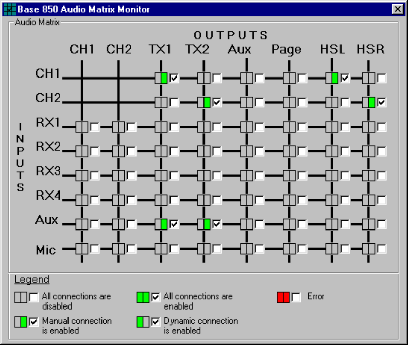
A particularly useful feature of PC850 is the ability to display (and alter) the audio connection matrix. This
window shows all possible and active audio connections. To open the window, select Audio Connection Matrix
from the View menu. Once open, the window will display all active connections as check marks beside a green
square. As connections change, the screen will be updated with the new information. To force a manual
32
connection, simply check the desired box(es). To break a connection, uncheck the desired box(es). Note that
two types of connections are shown: Manual connections and dynamic connections. Manual connections result
from configuration settings or functions. Dynamic connections result from Beltpac operations or the front panel
Talk button. Checking a box in the window always results in a manual connection. Manual connections are not
overridden by dynamic operations. However, clearing a connection manually does not prevent a later dynamic
or manual connection from being established. Note that the Audio Connection Matrix window can only be
opened while PC850 is “online”.

33
END-USER LICENSE AGREEMENT FOR HME PC850 SOFTWARE
IMPORTANT — READ CAREFULLY: This HME End-User License Agreement ("AGREEMENT") is a
legal agreement between you (either an individual or a single entity) and HM Electronics, Inc. (“HME”) for the
HME software product PC850, which includes computer software and may include associated registration files,
media, printed materials, sample documents, and "online" or electronic documentation ("SOFTWARE
PRODUCT"). The SOFTWARE PRODUCT also includes any updates and supplements to the original
SOFTWARE PRODUCT provided to you by HME. Any software provided along with the SOFTWARE
PRODUCT that is associated with a separate end-user license agreement is licensed to you under the terms of
that license agreement.
SOFTWARE PRODUCT LICENSE
The SOFTWARE PRODUCT is protected by copyright laws and international copyright treaties, as well
as other intellectual property laws and treaties. The SOFTWARE PRODUCT is licensed, not sold.
1) GRANT OF LICENSE. This AGREEMENT grants you the following rights:
a) Applications Software. As an individual, you are granted a world-wide non-exclusive license, which
includes only the right to install, use, access, display, run, or otherwise interact with ("RUN") one copy of
the SOFTWARE PRODUCT, or any prior version for the same operating system, on a single computer.
If you are an entity, you are granted the right to designate one individual within your organization to have
the right to use the SOFTWARE PRODUCT in the manner provided above.
b) Storage/Network Use. As an alternative to installing the SOFTWARE PRODUCT on a dedicated
computer, you may store or install the SOFTWARE PRODUCT on a storage device, such as a network
server, used only to RUN the SOFTWARE PRODUCT on your other COMPUTERS over an internal
network; however, you must acquire and dedicate a license for each separate COMPUTER on which the
SOFTWARE PRODUCT is RUN from the storage device. A license for the SOFTWARE PRODUCT may
not be shared or used concurrently on or by different COMPUTERS.
c) Reservation of Rights. All rights not expressly granted are reserved by HME.
2) DESCRIPTION OF OTHER RIGHTS AND LIMITATIONS.
a) Limitations on Reverse Engineering, Decompilation, and Disassembly. You may not reverse
engineer, decompile, or disassemble the SOFTWARE PRODUCT.
b) Separation of Components. The SOFTWARE PRODUCT is licensed as a single product. Its
component parts may not be separated for use on more than one COMPUTER.
c) Trademarks. This AGREEMENT does not grant you any rights in connection with any trademarks or
service marks of HME.
d) Rental. You may not rent, lease, or lend the SOFTWARE PRODUCT.
e) Support Services. HME may provide you with support services related to the SOFTWARE
PRODUCT ("Support Services"). Use of Support Services is governed by the HME policies and programs
described in the user manual, in "online" documentation, and/or in other HME-provided materials. Any
supplemental software code provided to you as part of the Support Services shall be considered part of the
SOFTWARE PRODUCT and subject to the terms and conditions of this AGREEMENT. With respect to
technical information you provide to HME as part of the Support Services, HME may use such information
for its business purposes, including for product support and development. HME will not utilize such
technical information in a form that personally identifies you.
By installing, copying, downloading, accessing, or otherwise using the SOFTWARE PRODUCT, you agree
to be bound by the terms of this AGREEMENT. If you do not agree to the terms of this AGREEMENT, do
not install or use the SOFTWARE PRODUCT; you may, however, return it to your place of purchase for a
full refund.
34
f) Software Transfer. The initial licensee of the SOFTWARE PRODUCT may make a one-time
permanent transfer of this AGREEMENT and SOFTWARE PRODUCT only directly to an end user. This
transfer must include all of the SOFTWARE PRODUCT (including all component parts, the media and
printed materials, any upgrades, this AGREEMENT, and, if applicable, the Certificate of Authenticity).
Such transfer may not be by way of consignment or any other indirect transfer. The transferee of such one-
time transfer must agree to comply with the terms of this AGREEMENT, including the obligation not to
further transfer this AGREEMENT and/or SOFTWARE PRODUCT.
g) Termination. Without prejudice to any other rights, HME may terminate this AGREEMENT if you
fail to comply with the terms and conditions of this AGREEMENT. In such event, you must destroy all
copies of the SOFTWARE PRODUCT and all of its component parts.
3) UPGRADES. If the SOFTWARE PRODUCT is labeled as an upgrade, you must be properly licensed to
use a product identified by HME as being eligible for the upgrade in order to use the SOFTWARE PRODUCT.
A SOFTWARE PRODUCT labeled as an upgrade replaces and/or supplements (and may disable) the product
that formed the basis for your eligibility for the upgrade. You may use the resulting upgraded product only in
accordance with the terms of this AGREEMENT. If the SOFTWARE PRODUCT is an upgrade of a
component of a package of software programs that you licensed as a single product, the SOFTWARE
PRODUCT may be used and transferred only as part of that single product package and may not be separated
for use on more than one COMPUTER.
4) COPYRIGHT. All title and copyrights in and to the SOFTWARE PRODUCT (including but not limited
to its code, appearance, structure, organization along with any documents, forms, text, and images incorporated
into the SOFTWARE PRODUCT), the accompanying printed materials, and any copies of the SOFTWARE
PRODUCT are owned by HME or its suppliers. All title and intellectual property rights in and to the content
that may be accessed through use of the SOFTWARE PRODUCT are the property of the respective content
owner and may be protected by applicable copyright or other intellectual property laws and treaties. This
AGREEMENT grants you no rights to use such content. If this SOFTWARE PRODUCT contains
documentation that is provided only in electronic form, you may print one copy of such electronic
documentation. You may not copy the printed materials accompanying the SOFTWARE PRODUCT.
5) BACKUP COPY. After installation of one copy of the SOFTWARE PRODUCT pursuant to this
AGREEMENT, you may keep the original media on which the SOFTWARE PRODUCT was provided by
HME solely for backup or archival purposes. If the original media is required to use the SOFTWARE
PRODUCT on the COMPUTER, you may make one copy of the SOFTWARE PRODUCT solely for backup or
archival purposes. Except as expressly provided in this AGREEMENT, you may not otherwise make copies of
the SOFTWARE PRODUCT or the printed materials accompanying the SOFTWARE PRODUCT.
6) EXPORT RESTRICTIONS. You agree that you will not export or re-export the SOFTWARE
PRODUCT, any part thereof, or any process or service that is the direct product of the SOFTWARE
PRODUCT (the foregoing collectively referred to as the “Restricted Components”), to any country, person or
entity subject to U.S. export restrictions. You specifically agree not to export or re-export any of the Restricted
Components (i) to any country to which the U.S. has embargoed or restricted the export of goods or services,
which currently include, but are not necessarily limited to Cuba, Iran, Iraq, Libya, North Korea, Sudan and
Syria, or to any national of any such country, wherever located, who intends to transmit or transport the
Restricted Components back to such country; (ii) to any person or entity who you know or have reason to know
will utilize the Restricted Components in the design, development or production of nuclear, chemical or
biological weapons; or (iii) to any person or entity who has been prohibited from participating in U.S. export
transactions by any federal agency of the U.S. government. You warrant and represent that neither the BXA
nor any other U.S. federal agency has suspended, revoked or denied your export privileges.
7) NO LEGAL ADVICE. You agree and acknowledge that HME is not engaged in rendering legal,
accounting, or other professional advice. If legal advice or other expert assistance is required, the services of a
competent professional person should be sought. Any sample documents included with the SOFTWARE
PRODUCT are for illustration only and should not be used as the basis for any transaction or advice.
35
8) MISCELLANEOUS
a) If you acquired this SOFTWARE PRODUCT in the United States, this AGREEMENT is governed by
the laws of the State of California.
b) If you acquired this SOFTWARE PRODUCT in Canada, unless expressly prohibited by local law, this
AGREEMENT is governed by the laws in force in the Province of Ontario, Canada; and, in respect of any
dispute which may arise hereunder, you consent to the jurisdiction of the federal and provincial courts
sitting in Toronto, Ontario. If this SOFTWARE PRODUCT was acquired outside the United States, then
local law may apply.
c) If you have any questions concerning this AGREEMENT, or if you desire to contact HME for any
reason, please write to: HM Electronics, Inc., 14110 Stowe Drive, Poway, California, 92064 U.S.A.
9) LIMITED WARRANTY
a) LIMITED WARRANTY FOR SOFTWARE PRODUCTS ACQUIRED IN THE U.S. AND
CANADA. HME warrants that (a) the SOFTWARE PRODUCT will perform substantially in accordance
with the accompanying written materials for a period of ninety (90) days from the date of receipt, and
(b) any Support Services provided by HME shall be substantially as described in applicable written
materials provided to you by HME, and HME support engineers will make commercially reasonable efforts
to solve any problem issues. Some states and jurisdictions do not allow limitations on duration of an
implied warranty, so the above limitation may not apply to you. To the extent allowed by applicable law
and not disclaimed in this Agreement, implied warranties on the SOFTWARE PRODUCT, if any, are
limited to ninety (90) days.
CUSTOMER REMEDIES. HME’s and its suppliers’ entire liability and your exclusive remedy shall be,
at HME’s option, either (a) return of the price paid, if any, or (b) repair or replacement of the SOFTWARE
PRODUCT that does not meet HME’s Limited Warranty and which is returned to HME with a copy of
your receipt. This Limited Warranty is void if failure of the SOFTWARE PRODUCT has resulted from
accident, abuse, or misapplication. Any replacement SOFTWARE PRODUCT will be warranted for the
remainder of the original warranty period or thirty (30) days, whichever is longer. Outside the United
States, neither these remedies nor any product support services offered by HME are available without proof
of purchase from an authorized international source.
c) NO OTHER WARRANTIES. THE LIMITED WARRANTY ABOVE IS EXCLUSIVE AND IN
LIEU OF ALL OTHER CONDITIONS AND WARRANTIES FOR THE SOFTWARE AND
DOCUMENTATION. HME AND ITS SUPPLIERS MAKE NO OTHER CONDITIONS OR
WARRANTIES, EXPRESS, IMPLIED, STATUTORY OR OTHERWISE, AND EXPRESSLY
DISCLAIM ALL OTHER CONDITIONS AND WARRANTIES, INCLUDING BUT NOT LIMITED TO
IMPLIED CONDITIONS OR IMPLIED WARRANTIES OF MERCHANTABILITY, FITNESS FOR A
PARTICULAR PURPOSE, AND NONINFRINGEMENT FOR THE SOFTWARE AND
DOCUMENTATION, TO THE FULLEST EXTENT PERMITTED BY APPLICABLE LAW.
d) LIMITED LIABILITY. TO THE MAXIMUM EXTENT PERMITTED BY APPLICABLE LAW,
IN NO EVENT AND UNDER NO LEGAL THEORY SHALL HME OR ITS SUPPLIERS BE LIABLE
TO YOU FOR ANY COSTS OF SUBSTITUTE PRODUCTS, OR FOR ANY CONSEQUENTIAL,
SPECIAL, INCIDENTAL, PUNITIVE OR INDIRECT DAMAGES OF ANY KIND ARISING OUT OF
THE LICENSE OF, USE OF, OR INABILITY TO USE ANY HME SOFTWARE OR
DOCUMENTATION, EVEN IF HME HAS BEEN ADVISED OF THE POSSIBILITY OF SUCH
DAMAGES. IN NO EVENT SHALL HME'S OR ITS SUPPLIERS' LIABILITY EXCEED THE
LICENSE FEE PAID BY YOU. THIS LIMITATION OF LIABILITY AND RISKS IS REFLECTED IN
THE PRICE OF THE SOFTWARE LICENSE.
10) AUDIT. During the term of this Agreement and for three (3) years after termination or expiration, you
will maintain complete records regarding your use and distribution of the Software. Upon reasonable notice to
you, HME may audit, at HME's expense, your books and records to determine your compliance hereunder. In
the event any such audit reveals that you have underpaid HME by an amount greater than five percent (5%) of
the amounts due HME in the period being audited, or that you have knowingly breached any material obligation
hereunder, then, in addition to such other remedies as HME may have, you shall pay or reimburse to HME the
cost of the audit.
36
11) U.S. GOVERNMENT RESTRICTED RIGHTS. The Software and accompanying documentation are
deemed to be "commercial computer software" and "commercial computer software documentation,"
respectively, pursuant to DFAR Section 227.7202 and FAR Section 12.212, as applicable. Any use,
modification, reproduction, release, performance, display or disclosure of the software and accompanying
documentation by the U.S. Government shall be governed solely by the terms of this Agreement and shall be
prohibited except to the extent expressly permitted by the terms of this Agreement.
You must affix the following legend to each copy of the Software:
Use, duplication, reproduction, or transfer of this commercial Software and accompanying documentation is
restricted in accordance with FAR 12.212 and DFARS 227.7202 and by a license agreement.
Contact HM Electronics, Inc., 14110 Stowe Drive, Poway, California, 92064 U.S.A.
HME DISCLAIMS ANY REPRESENTATION OR WARRANTY MADE BY ANY DISTRIBUTOR,
RESELLER OR DEALER TO YOU WHETHER EXPRESS OR IMPLIED.
Should you have any questions concerning this AGREEMENT, or if you desire to contact HME for any reason,
please contact us: HM Electronics, Inc., 14110 Stowe Drive, Poway, California, 92064, U.S.A.