HM Electronics COM400 COM400BP Communicator User Manual U WP PUBS IN WORK 400490 400490
HM Electronics Inc COM400BP Communicator U WP PUBS IN WORK 400490 400490
UserManual.wiki
>
HM Electronics
>
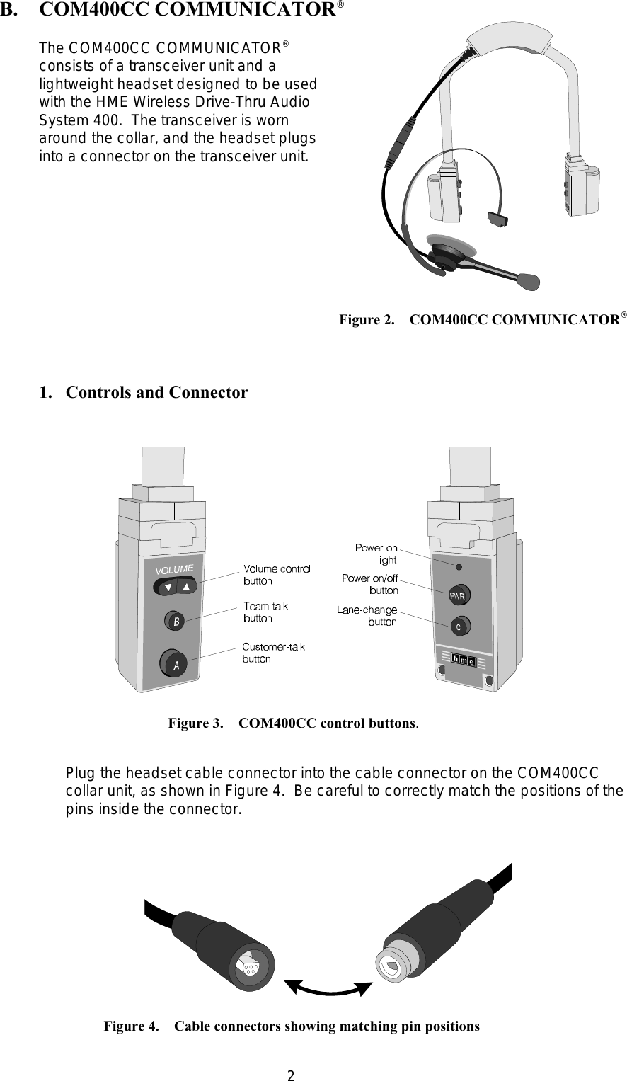
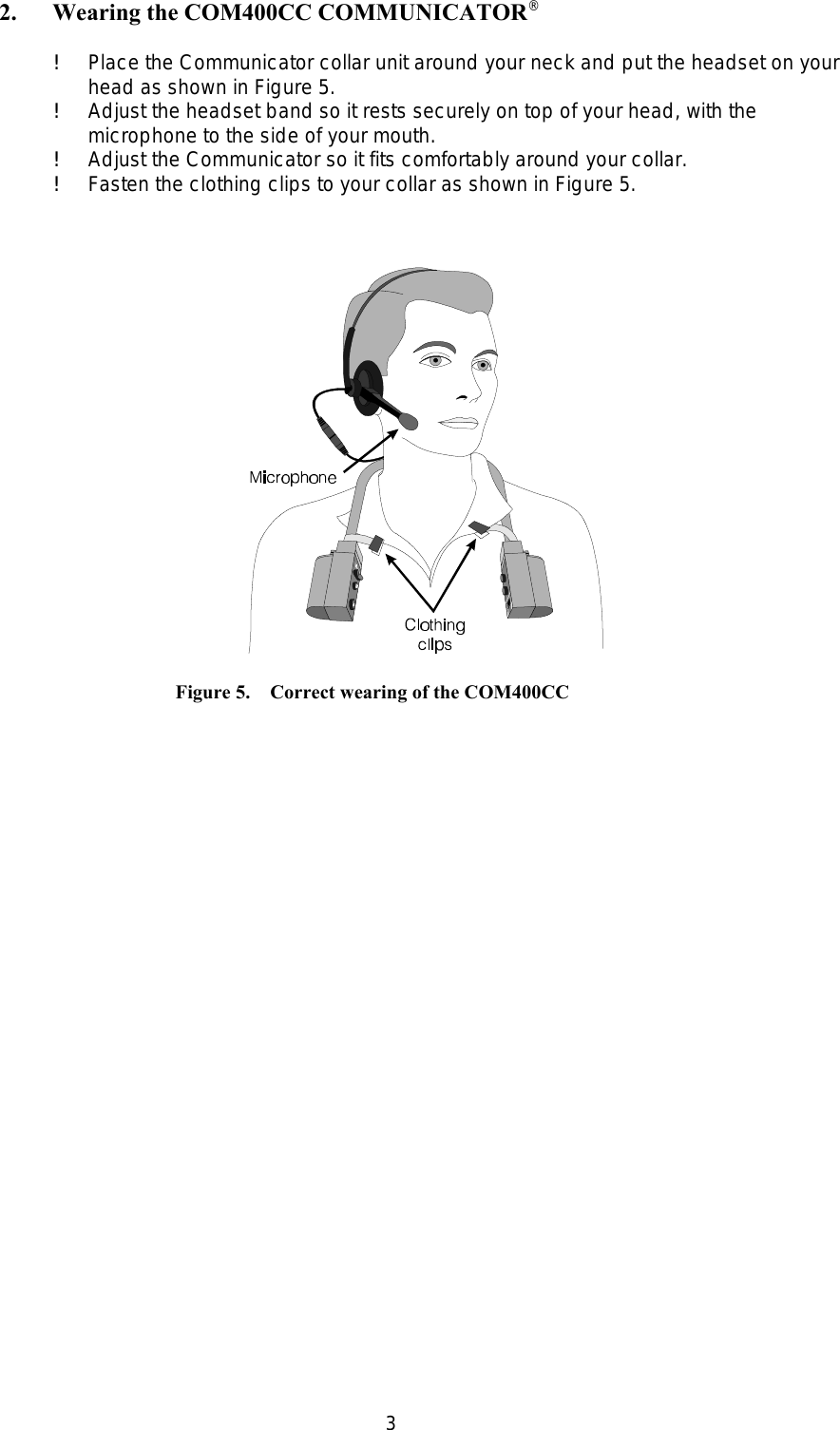
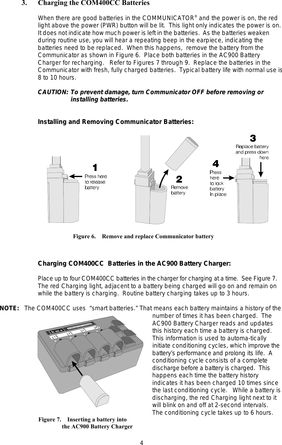
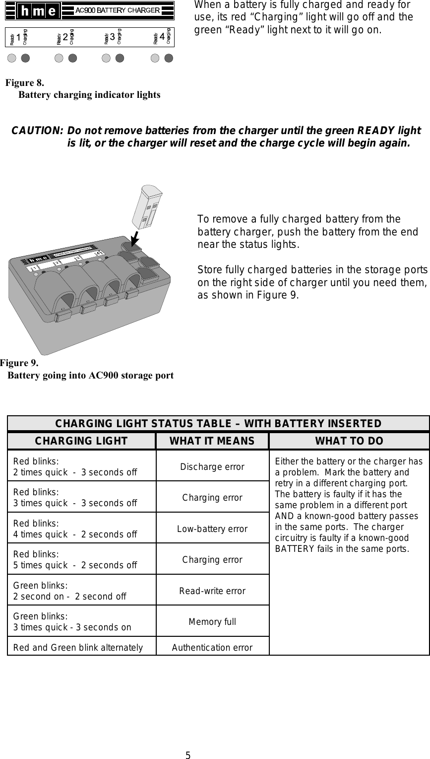
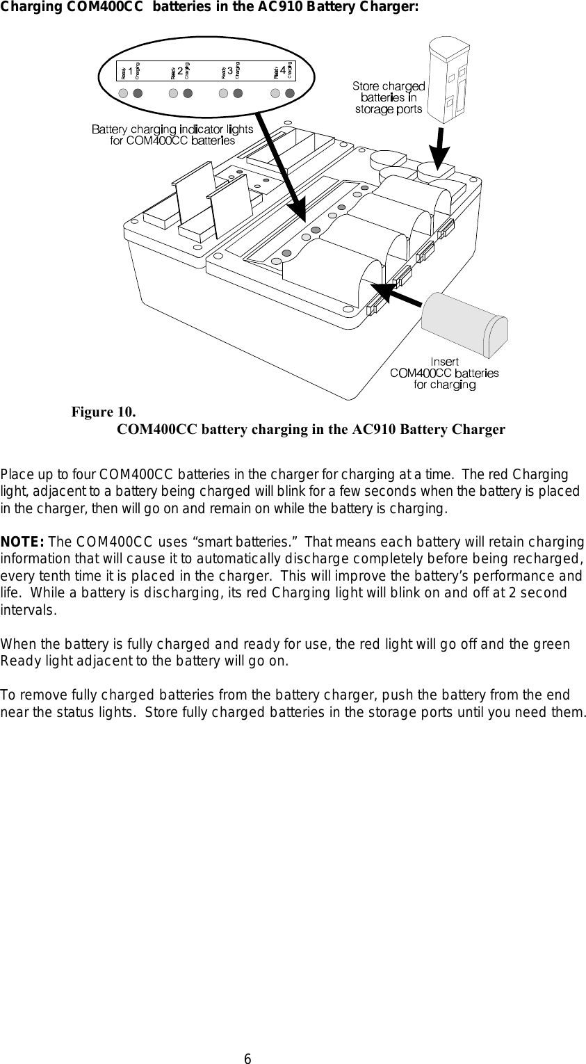
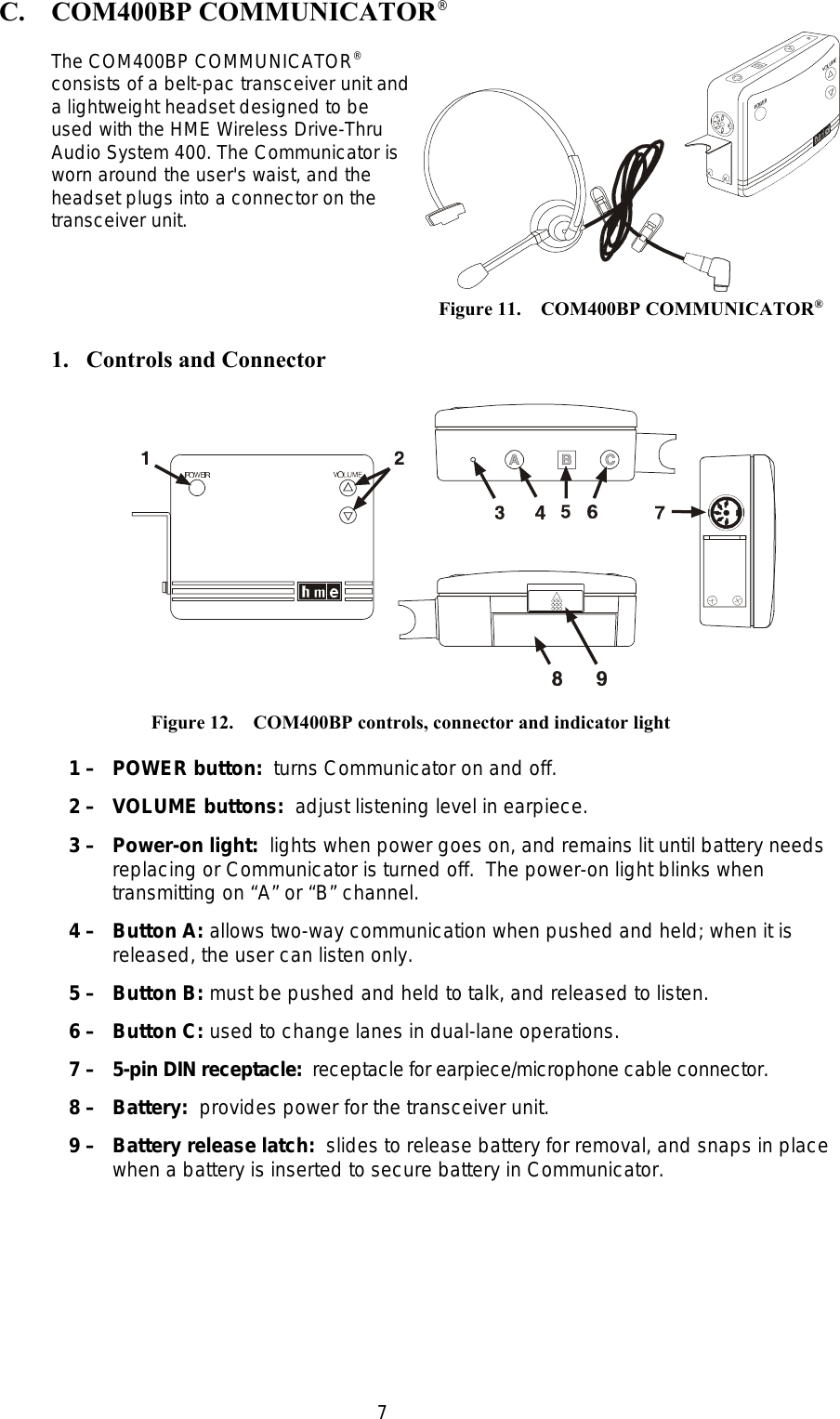
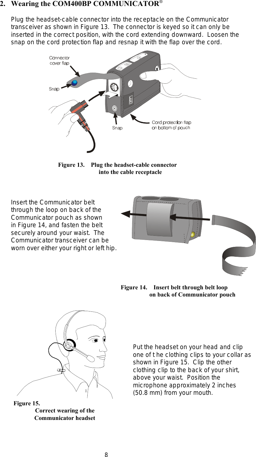
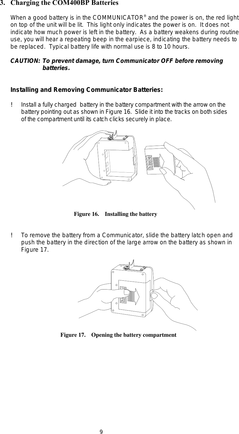
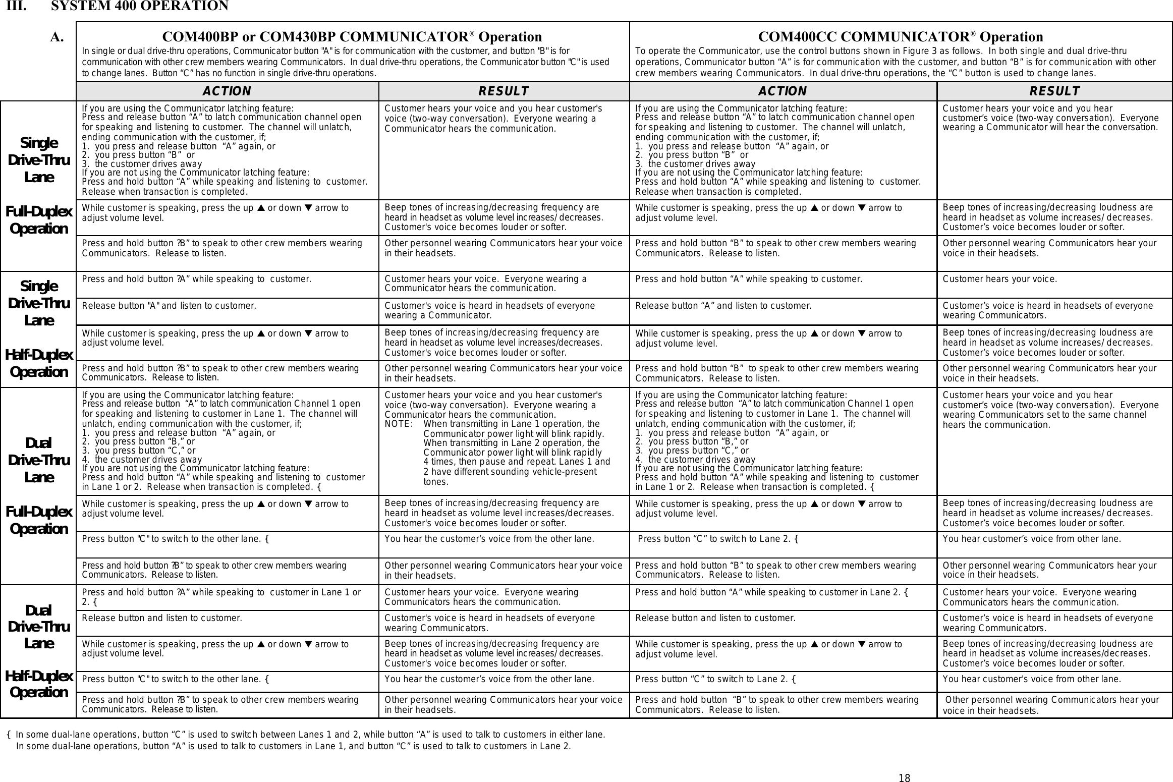
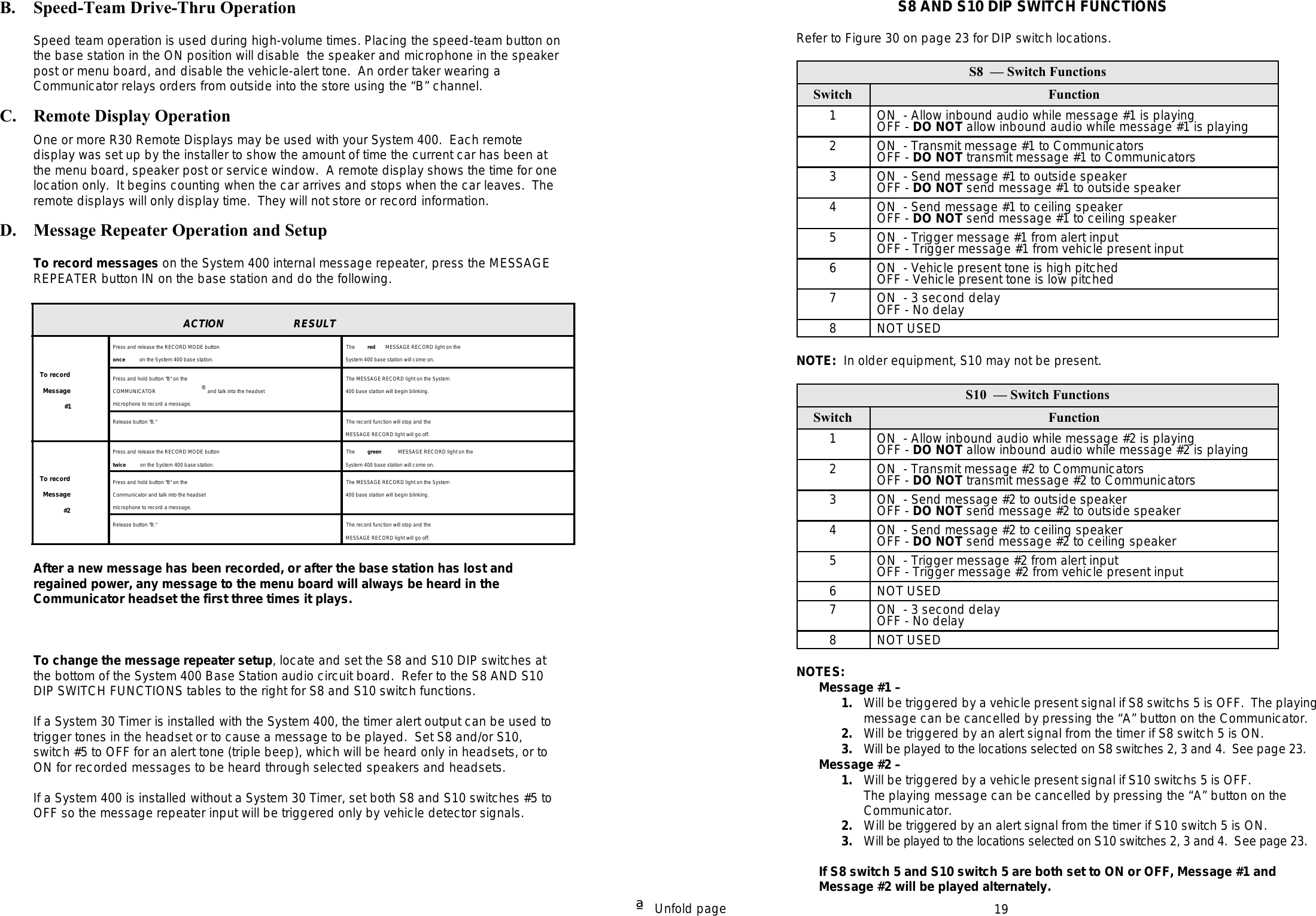
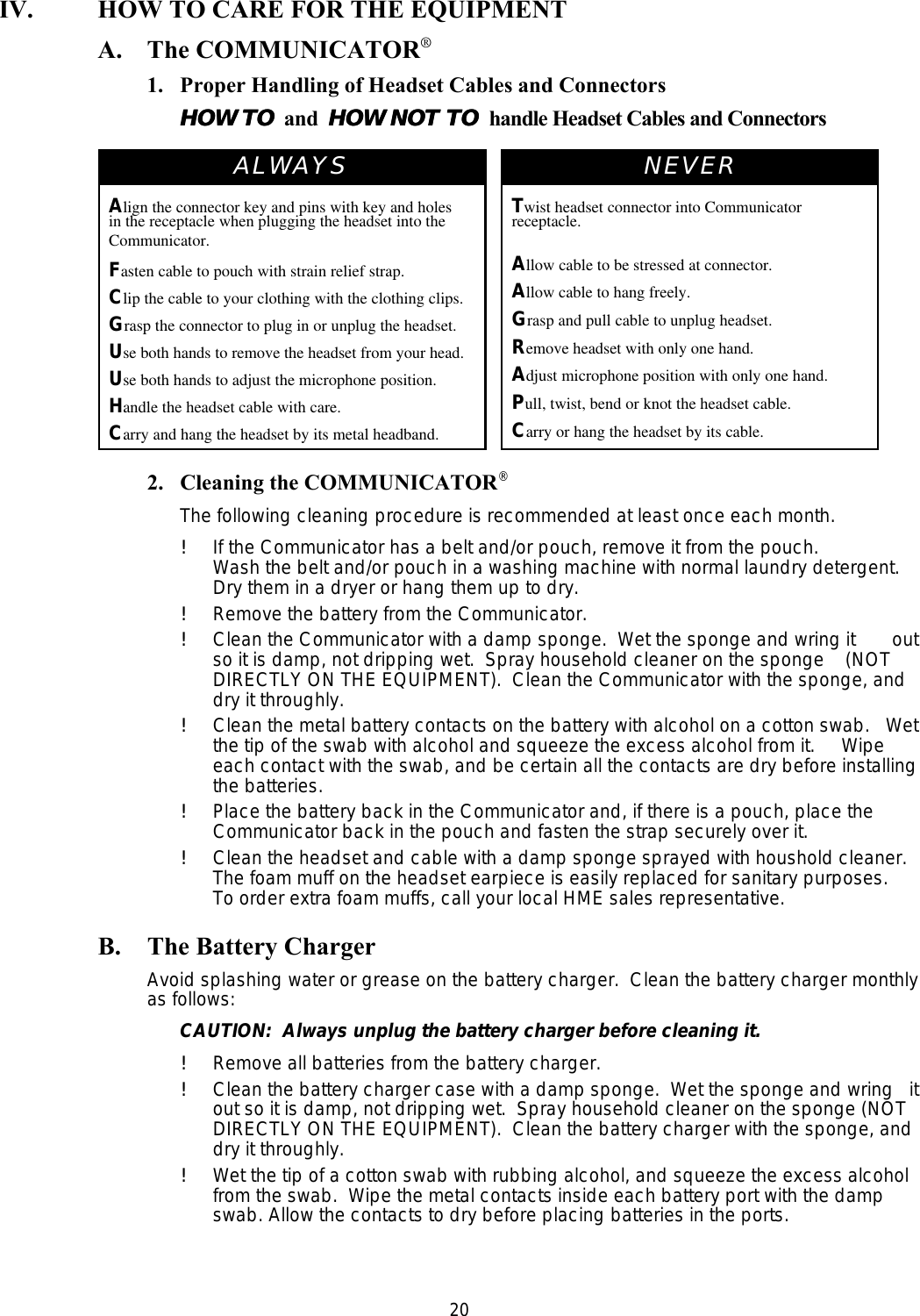
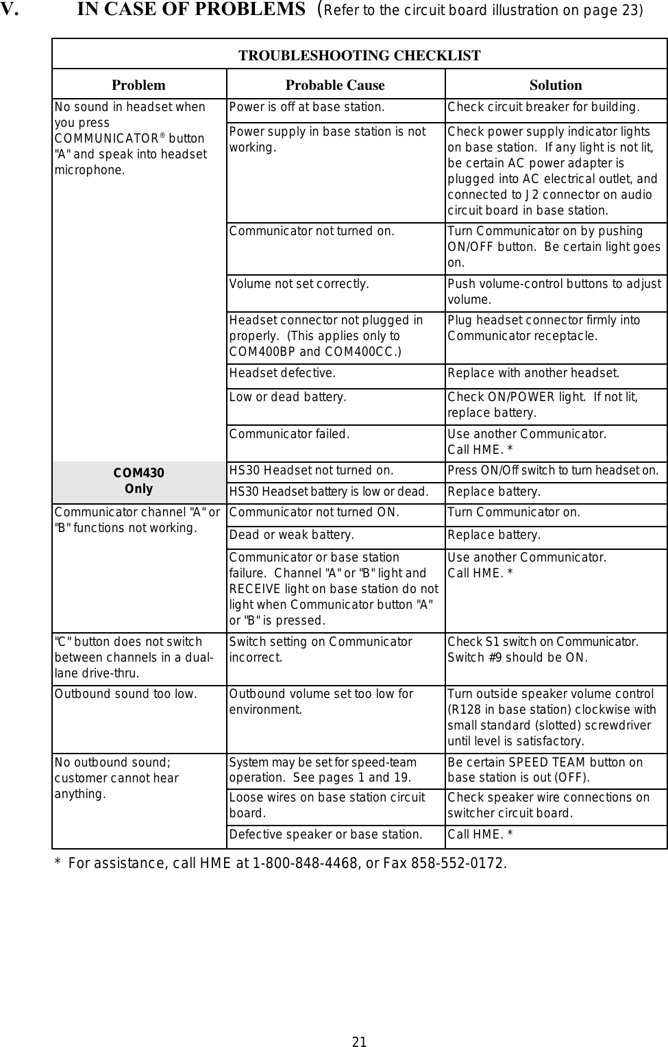
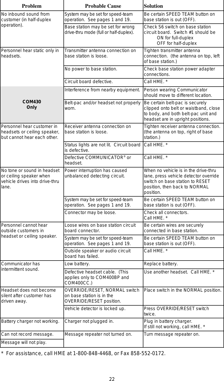
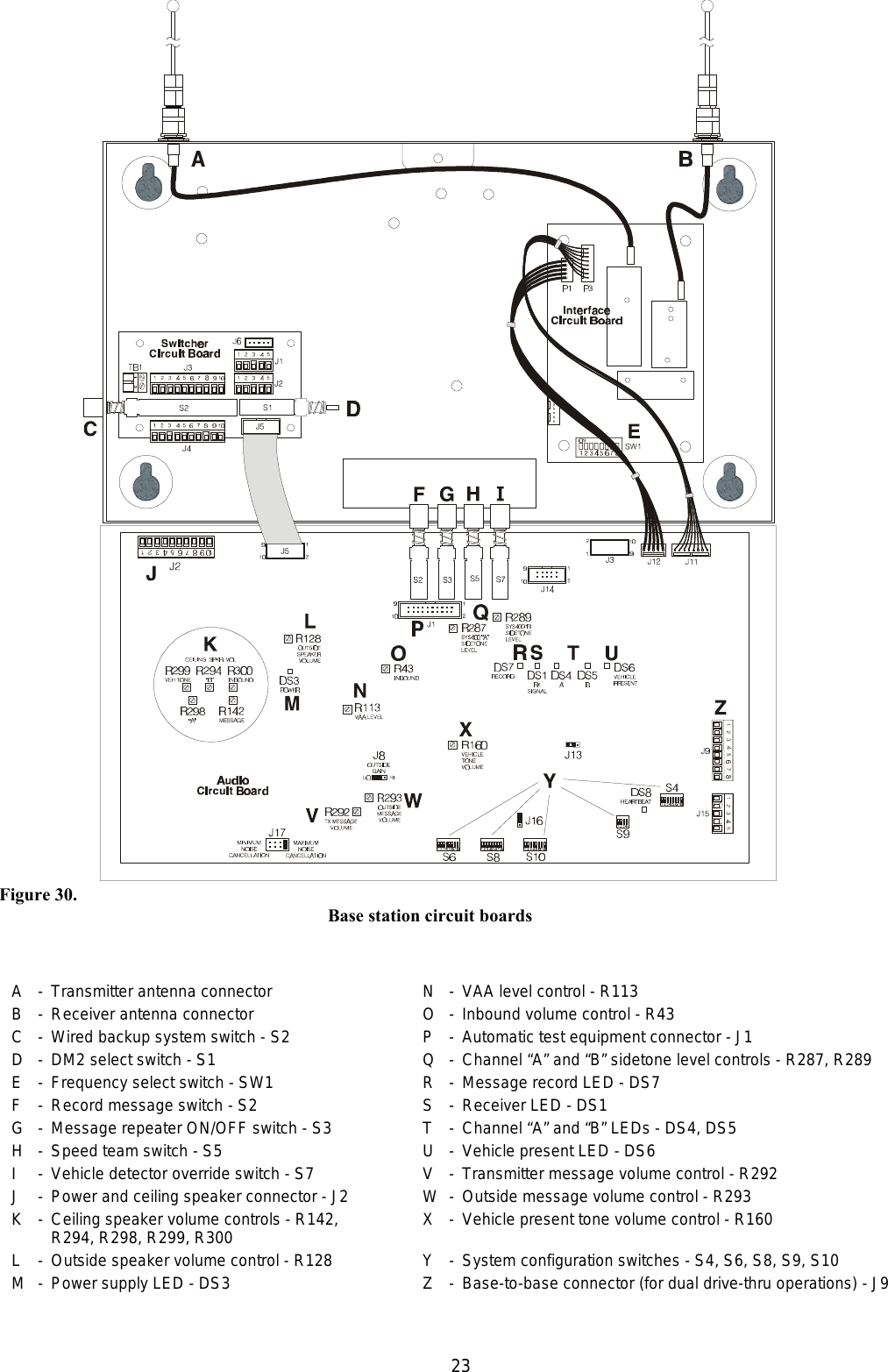
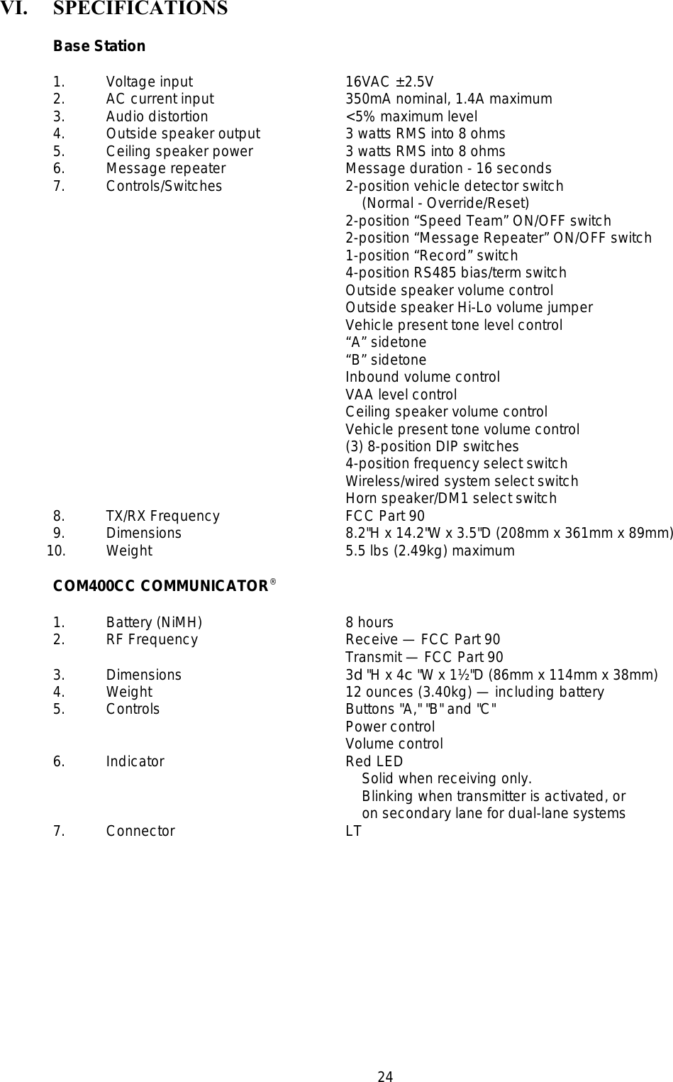
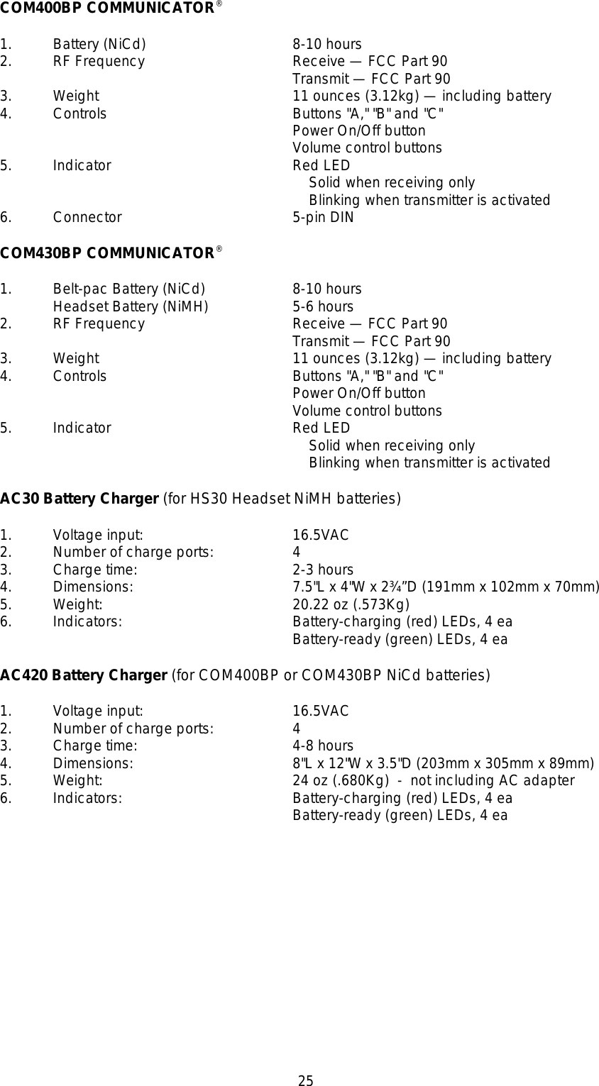
COM400 User Manual
user manual
Navigation menu
Upload a User Manual
Namespaces
Wiki Guide
HTML
PDF
Info
Views
User Manual
Discussion / Help
Navigation