HM Electronics COM400 COM400BP Communicator User Manual U WP PUBS IN WORK 400490 400490
HM Electronics Inc COM400BP Communicator U WP PUBS IN WORK 400490 400490
user manual

HME#
400490
Rev A 11/13/02
System 400
Wireless Audio System
Operating Instructions
(For Full-Duplex and Half-Duplex Operations)
Table of Contents
I. GENERAL .................................................... 1
II. EQUIPMENT FUNCTIONS AND USE ............................... 1
A. Base Station ................................................ 1
B. COM400CC COMMUNICATOR ................................ 2
®
1. Controls and Connector .................................... 2
2. Wearing the COM400CC COMMUNICATOR ................... 3
®
3. Charging the COM400CC Batteries .......................... 4
C. COM400BP COMMUNICATOR ................................ 7
®
1. Controls and Connector .................................... 7
2. Wearing the COM400BP COMMUNICATOR ................... 8
®
3. Charging the COM400BP Batteries ........................... 9
D. COM430BP COMMUNICATOR ............................... 12
®
1. Communicator Controls ................................... 12
2. Wearing the COM430BP COMMUNICATOR .................. 13
®
3. Charging the COM430BP Batteries .......................... 14
III. SYSTEM 400 OPERATION ...................................... 18
A. COMMUNICATOR Operation ................................. 18
®
B. Speed-Team Drive-Thru Operation ............................. 19
C. Remote Display Operation .................................... 19
D. Message Repeater Operation and Setup ......................... 19
IV. HOW TO CARE FOR THE EQUIPMENT ............................ 20
A. The COMMUNICATOR ...................................... 20
®
1. Proper Handling of Headset Cables and Connectors ............. 20
2. Cleaning the Equipment ................................... 20
B. The Battery Charger ......................................... 20
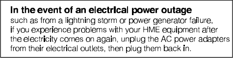
V. IN CASE OF PROBLEMS ........................................ 21
VI. SPECIFICATIONS ............................................. 24
VII. ACCESSORIES AND OPTIONAL EQUIPMENT ...................... 27
VIII. FCC NOTICE ................................................. 27
The HME logo and the word COMMUNICATOR are registered trademarks of HM Electronics, Inc.
®
© Copyright HM Electronics, Inc. — November 2002
List of Figures
Figure Title Page
1 System 400 Base Station ........................................ 1
2 COM400CC COMMUNICATOR .................................. 2
®
3 COM400CC control buttons ...................................... 2
4 Cable connectors showing matching pin positions .................... 2
5 Correct wearing of the COM400CC ................................ 3
6 Remove and replace Communicator batteries ....................... 4
7 Inserting a battery into the AC900 Battery Charger .................... 4
8 Battery charging indicator lights ................................... 5
9 Battery going into AC900 storage port .............................. 5
10 COM400CC battery charging in the AC910 Battery Charger ............ 6
11 COM400BP COMMUNICATOR .................................. 7
®
12 COM400BP controls, connector and indicator light .................... 7
13 Plug the headset-cable connector into the cable receptacle ............. 8
14 Insert belt through belt loop on back of Communicator pouch ............ 8
15 Correct wearing of Communicator headset .......................... 8
16 Installing the battery ............................................ 9
17 Opening the battery compartment ................................. 9
18 AC420 Battery Charger shown with a properly installed battery ......... 10
19 COM400BP battery charging in the AC910 Battery Charger ............ 11
20 COM430BP COMMUNICATOR ................................. 12
®
21 Communicator controls ......................................... 12
22 Communicator transceiver in pouch ............................... 13
23 Correct wearing of the COM430BP ............................... 13
24 Installing the COM430BP battery ................................. 14
25 Opening the COM430BP battery compartment ...................... 14
26 HS30 Headset ............................................... 15
27 HS30 Headset transceiver ...................................... 15
28 AC30 Battery Charger ......................................... 16
29 AC930 Battery Charger ........................................ 17
30 Base station circuit boards ...................................... 23
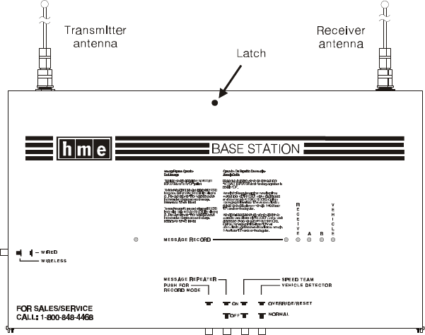
1
Figure 1. System 400 Base Station
I. GENERAL
The System 400 is a wireless audio system primarily for use at quick-service restaurants.
II. EQUIPMENT FUNCTIONS AND USE
A. Base Station
Front –
System indicator lights
!! POWER light is on when the base station has power.
!! MESSAGE RECORD light is on RED when the base station is ready to record
message #1 for the message repeater, and blinking RED while message #1 is
being recorded. It is on GREEN when the base station is ready to record
message #2 for the message repeater, and blinking GREEN while message #2
is being recorded. The MESSAGE REPEATER button must be pushed IN.
!! RECEIVE light is used only for troubleshooting, but is also on during channel-A
and channel-B transmissions.
!! “A” light is on during channel-A transmission.
!! “B” light is on during channel-B transmission.
!! VEHICLE light is on when a vehicle is present in the drive-thru lane or when
the system is in vehicle-detect override.
Bottom –
!! PUSH FOR RECORD MODE button; must be pushed IN and released once to
prepare the base station to record message #1 for the message repeater, or
pushed IN and released twice to record message #2.
!! MESSAGE REPEATER button; must be pushed IN to use the message
repeater, OUT when the message repeater is not being used.
!! SPEED TEAM button; must be pushed IN for speed-team operation, OUT for
normal drive-thru operation
!! VEHICLE DETECTOR button; to override a vehicle detector, push and leave
IN: to reset vehicle detector, push IN and leave In for 5 seconds, then push
again and leave OUT for normal vehicle detection.
Left Side –
!! WIRED/WIRELESS button; must be OUT when using the wireless
System 400, IN when using a wired backup system.
2
Figure 2. COM400CC COMMUNICATOR®
Figure 3. COM400CC control buttons.
Figure 4. Cable connectors showing matching pin positions
B. COM400CC COMMUNICATOR
®
The COM400CC COMMUNICATOR®
consists of a transceiver unit and a
lightweight headset designed to be used
with the HME Wireless Drive-Thru Audio
System 400. The transceiver is worn
around the collar, and the headset plugs
into a connector on the transceiver unit.
1. Controls and Connector
Plug the headset cable connector into the cable connector on the COM400CC
collar unit, as shown in Figure 4. Be careful to correctly match the positions of the
pins inside the connector.
3
Figure 5. Correct wearing of the COM400CC
2. Wearing the COM400CC COMMUNICATOR
®
!Place the Communicator collar unit around your neck and put the headset on your
head as shown in Figure 5.
!Adjust the headset band so it rests securely on top of your head, with the
microphone to the side of your mouth.
!Adjust the Communicator so it fits comfortably around your collar.
!Fasten the clothing clips to your collar as shown in Figure 5.
4
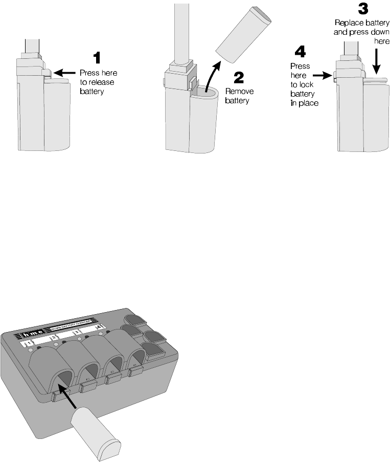
Figure 6. Remove and replace Communicator battery
Figure 7. Inserting a battery into
the AC900 Battery Charger
3. Charging the COM400CC Batteries
When there are good batteries in the COMMUNICATOR and the power is on, the red
®
light above the power (PWR) button will be lit. This light only indicates the power is on.
It does not indicate how much power is left in the batteries. As the batteries weaken
during routine use, you will hear a repeating beep in the earpiece, indicating the
batteries need to be replaced. When this happens, remove the battery from the
Communicator as shown in Figure 6. Place both batteries in the AC900 Battery
Charger for recharging. Refer to Figures 7 through 9. Replace the batteries in the
Communicator with fresh, fully charged batteries. Typical battery life with normal use is
8 to 10 hours.
CAUTION: To prevent damage, turn Communicator OFF before removing or
installing batteries.
Installing and Removing Communicator Batteries:
Charging COM400CC Batteries in the AC900 Battery Charger:
Place up to four COM400CC batteries in the charger for charging at a time. See Figure 7.
The red Charging light, adjacent to a battery being charged will go on and remain on
while the battery is charging. Routine battery charging takes up to 3 hours.
NOTE: The COM400CC uses “smart batteries.” That means each battery maintains a history of the
number of times it has been charged. The
AC900 Battery Charger reads and updates
this history each time a battery is charged.
This information is used to automa-tically
initiate conditioning cycles, which improve the
battery’s performance and prolong its life. A
conditioning cycle consists of a complete
discharge before a battery is charged. This
happens each time the battery history
indicates it has been charged 10 times since
the last conditioning cycle. While a battery is
discharging, the red Charging light next to it
will blink on and off at 2-second intervals.
The conditioning cycle takes up to 6 hours.
5
Figure 8.
Battery charging indicator lights
Figure 9.
Battery going into AC900 storage port
When a battery is fully charged and ready for
use, its red “Charging” light will go off and the
green “Ready” light next to it will go on.
CAUTION: Do not remove batteries from the charger until the green READY light
is lit, or the charger will reset and the charge cycle will begin again.
To remove a fully charged battery from the
battery charger, push the battery from the end
near the status lights.
Store fully charged batteries in the storage ports
on the right side of charger until you need them,
as shown in Figure 9.
CHARGING LIGHT STATUS TABLE – WITH BATTERY INSERTED
CHARGING LIGHT WHAT IT MEANS WHAT TO DO
Red blinks: Either the battery or the charger has
2 times quick - 3 seconds off a problem. Mark the battery and
Discharge error
retry in a different charging port.
The battery is faulty if it has the
same problem in a different port
AND a known-good battery passes
in the same ports. The charger
circuitry is faulty if a known-good
BATTERY fails in the same ports.
Red blinks:
3 times quick - 3 seconds off Charging error
Red blinks:
4 times quick - 2 seconds off Low-battery error
Red blinks:
5 times quick - 2 seconds off Charging error
Green blinks:
2 second on - 2 second off Read-write error
Green blinks:
3 times quick - 3 seconds on Memory full
Red and Green blink alternately Authentication error
6
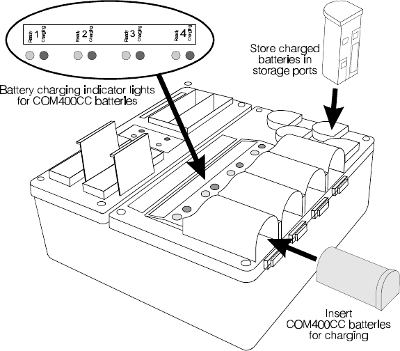
Figure 10.
COM400CC battery charging in the AC910 Battery Charger
Charging COM400CC batteries in the AC910 Battery Charger:
Place up to four COM400CC batteries in the charger for charging at a time. The red Charging
light, adjacent to a battery being charged will blink for a few seconds when the battery is placed
in the charger, then will go on and remain on while the battery is charging.
NOTE: The COM400CC uses “smart batteries.” That means each battery will retain charging
information that will cause it to automatically discharge completely before being recharged,
every tenth time it is placed in the charger. This will improve the battery’s performance and
life. While a battery is discharging, its red Charging light will blink on and off at 2 second
intervals.
When the battery is fully charged and ready for use, the red light will go off and the green
Ready light adjacent to the battery will go on.
To remove fully charged batteries from the battery charger, push the battery from the end
near the status lights. Store fully charged batteries in the storage ports until you need them.
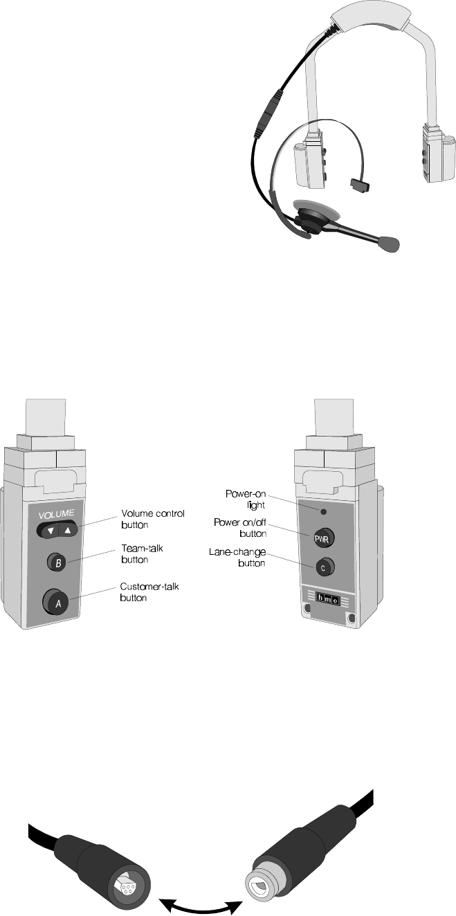
7
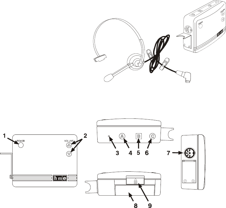
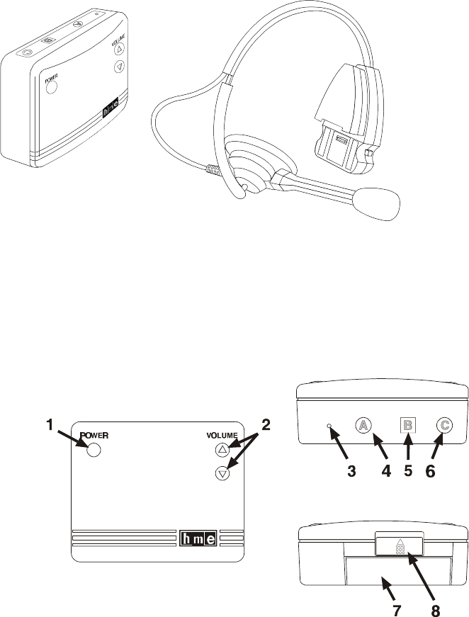
Figure 11. COM400BP COMMUNICATOR®
Figure 12. COM400BP controls, connector and indicator light
C. COM400BP COMMUNICATOR
®
The COM400BP COMMUNICATOR®
consists of a belt-pac transceiver unit and
a lightweight headset designed to be
used with the HME Wireless Drive-Thru
Audio System 400. The Communicator is
worn around the user's waist, and the
headset plugs into a connector on the
transceiver unit.
1. Controls and Connector
1 – POWER button: turns Communicator on and off.
2 – VOLUME buttons: adjust listening level in earpiece.
3 – Power-on light: lights when power goes on, and remains lit until battery needs
replacing or Communicator is turned off. The power-on light blinks when
transmitting on “A” or “B” channel.
4 – Button A: allows two-way communication when pushed and held; when it is
released, the user can listen only.
5 – Button B: must be pushed and held to talk, and released to listen.
6 – Button C: used to change lanes in dual-lane operations.
7 – 5-pin DIN receptacle: receptacle for earpiece/microphone cable connector.
8 – Battery: provides power for the transceiver unit.
9 – Battery release latch: slides to release battery for removal, and snaps in place
when a battery is inserted to secure battery in Communicator.
8
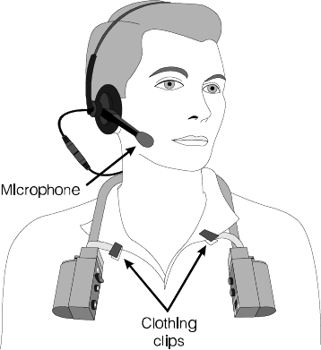
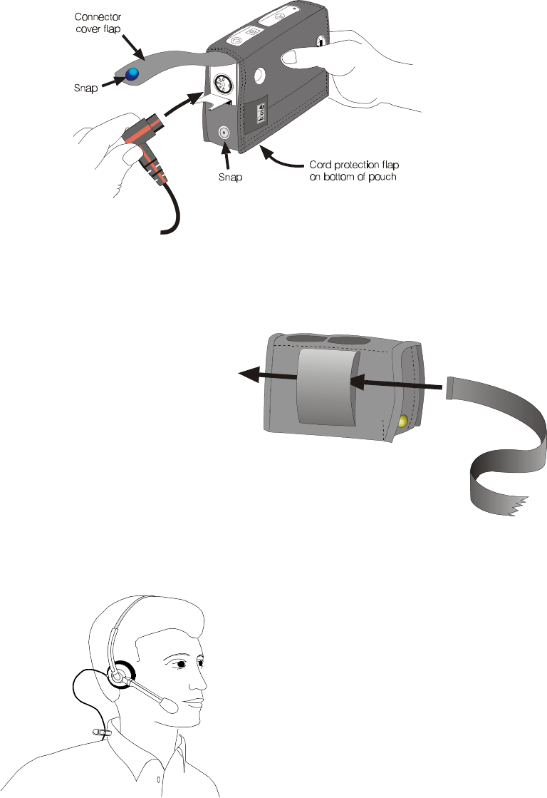
Figure 13. Plug the headset-cable connector
into the cable receptacle
Figure 14. Insert belt through belt loop
on back of Communicator pouch
Figure 15.
Correct wearing of the
Communicator headset
2. Wearing the COM400BP COMMUNICATOR®
Plug the headset-cable connector into the receptacle on the Communicator
transceiver as shown in Figure 13. The connector is keyed so it can only be
inserted in the correct position, with the cord extending downward. Loosen the
snap on the cord protection flap and resnap it with the flap over the cord.
Insert the Communicator belt
through the loop on back of the
Communicator pouch as shown
in Figure 14, and fasten the belt
securely around your waist. The
Communicator transceiver can be
worn over either your right or left hip.
Put the headset on your head and clip
one of t he clothing clips to your collar as
shown in Figure 15. Clip the other
clothing clip to the back of your shirt,
above your waist. Position the
microphone approximately 2 inches
(50.8 mm) from your mouth.
9
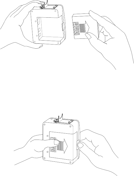
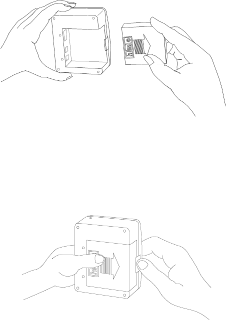
Figure 16. Installing the battery
Figure 17. Opening the battery compartment
3. Charging the COM400BP Batteries
When a good battery is in the COMMUNICATOR and the power is on, the red light
®
on top of the unit will be lit. This light only indicates the power is on. It does not
indicate how much power is left in the battery. As a battery weakens during routine
use, you will hear a repeating beep in the earpiece, indicating the battery needs to
be replaced. Typical battery life with normal use is 8 to 10 hours.
CAUTION: To prevent damage, turn Communicator OFF before removing
batteries.
Installing and Removing Communicator Batteries:
!Install a fully charged battery in the battery compartment with the arrow on the
battery pointing out as shown in Figure 16. Slide it into the tracks on both sides
of the compartment until its catch clicks securely in place.
!To remove the battery from a Communicator, slide the battery latch open and
push the battery in the direction of the large arrow on the battery as shown in
Figure 17.
10
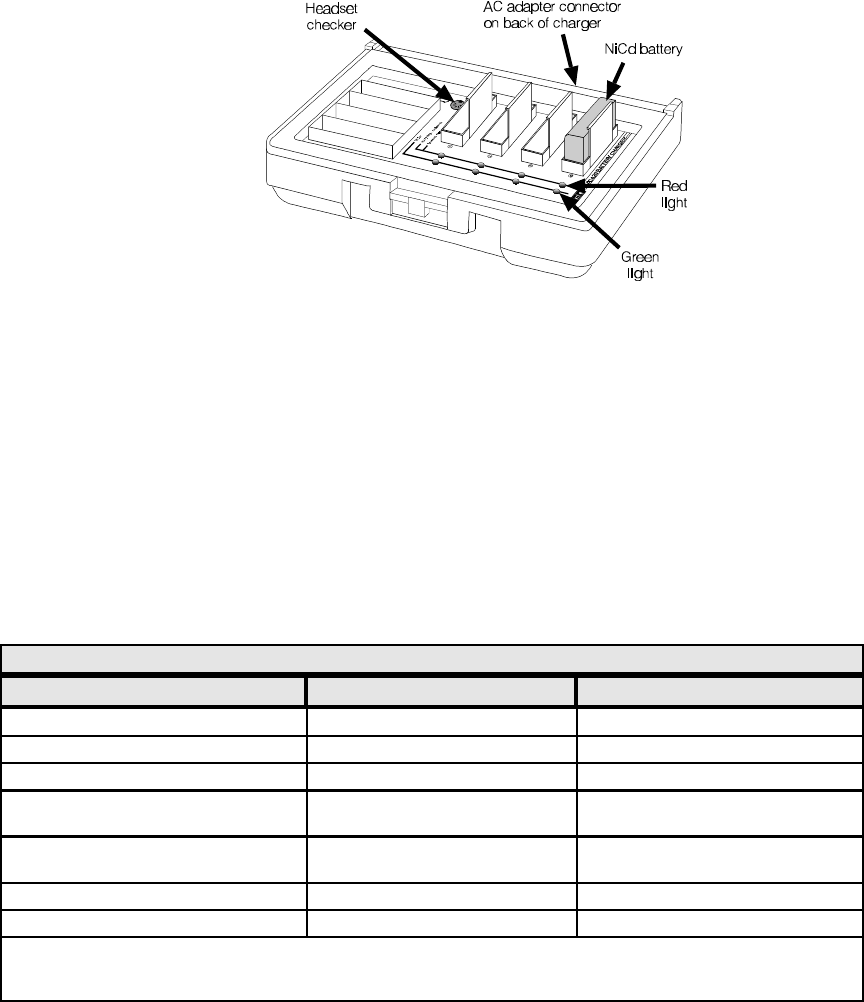
Figure 18.
AC420 Battery Charger shown with a properly installed battery
Charging COM400BP Batteries in the AC420 Battery Charger:
Place up to four batteries in the charger to charge at the same time, as shown in
Figure 18. A few seconds after each battery is placed in the charger, the red
CHARGING light on the panel adjacent to the battery, will indicate the battery
charging status. See the CHARGING LIGHT STATUS TABLE for a detailed
explanation of what is happening. When a battery is fully charged, the green
READY light on the panel adjacent to it will light. (approximately 4 hours)
It can then be placed back into a Communicator.
CAUTION: Do not remove batteries from the charger until the green READY
light is lit, or the charger will reset and the charge cycle will begin
again.
Top – Red lights indicate charging status of batteries below the lights, as shown on
the Charging Light Status Table below.
Green lights indicate batteries below the lights are fully charged and ready for use.
Headset checker is used to check headsets for normal operation. Plug the
headset cable connector into the headset connector receptacle and speak into
the headset microphone. If the headset is operating normally, you will hear your
own voice in the earpiece. If the headset is defective, you will hear nothing.
Back –
AC adapter connector is for connecting the AC adapter cable to the charger.
CHARGING LIGHT STATUS TABLE – WITH BATTERY INSERTED
RED CHARGING LIGHT WHAT IT MEANS WHAT TO DO
OFF Charger doesn’t see the battery See NOTE
STEADY ON Battery is being charged Wait. Do not remove battery.
BLINKS: 2 seconds ON; 2 seconds OFF Battery is being discharged. Wait. Do not remove battery.
BLINKS: 2 times quick; 3 seconds OFF DISCHARGE ERROR Battery is not discharging properly.
See NOTE.
BLINKS: 3 times quick; 3 seconds OFF CHARGING ERROR Battery is not charging properly.
See NOTE.
BLINKS: 4 times quick; 2 seconds OFF LOW BATTERY ERROR See NOTE.
BLINKS: 5 times quick; 2 seconds OFF CHARGING ERROR See NOTE.
NOTE: Either the battery or the charger has a problem. Mark the battery and retry in a different slot. The battery is faulty if
it has the same problem in a different slot AND a known-good battery passes in the same slots. The charger circuitry is
faulty if a known-good BATTERY fails in the same slots.
11
Figure 19. COM400BP battery charging in the AC910 Battery Charger
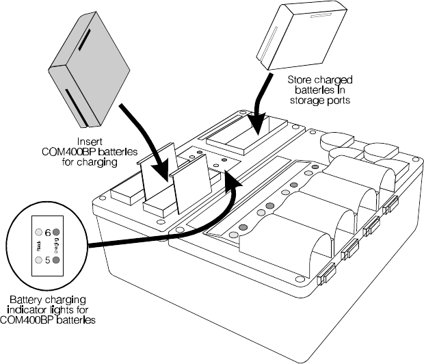
Charging COM400BP batteries in the AC910 Battery Charger:
Place up to two COM400BP batteries in the charger to charge at the same time. A few
seconds after each battery is placed in the charger, the red CHARGING light on the panel
adjacent to the battery, will indicate the battery charging status. See the CHARGING
LIGHT STATUS TABLE for a detailed explanation of what is happening. When a battery is
fully charged, the green READY light on the panel adjacent to it will light.
(approximately 4 hours) It can then be placed back into a COMMUNICATOR .
®
CAUTION: Do not remove batteries from the charger until the green READY
light is lit, or the charger will reset and the charge cycle will begin
again.
12
Figure 20. COM430BP COMMUNICATOR®
Figure 21. Communicator controls
D. COM430BP COMMUNICATOR®
The COM430BP COMMUNICATOR consists of a belt-pac transceiver unit and a
®
wireless headset designed to be used with the HME Wireless Drive-Thru Audio
System 400. The transceiver unit is worn in a pouch that clips to a belt or
waistband at the user's waist.
1. Communicator Controls
1 – Power button: turns Communicator on and off.
2 – Volume control buttons: adjust listening level in earpiece.
3 – Power-on light: lights yellow when Communicator power goes on, and
red when the HS30 Headset is also turned on. The power-on light also
indicates when the Communicator is transmitting in single or dual-lane
mode and when batteries need replacing.
4 – Button A: allows two-way communication when pushed and held; when it is
released, the user can listen only.
5 – Button B: must be pushed and held to talk, and released to listen.
6 – Button C: used to change lanes in dual-lane operations.
7 – Battery: provides power for the transceiver unit.
8 – Battery release latch: slides to release battery for removal, and snaps in
place when a battery is inserted to secure battery in Communicator.
13
Figure 22.
Communicator transceiver in pouch
Figure 23.
Correct wearing of COM430BP
Handsfree mode –
To turn Handsfree mode on: With the Communicator OFF, press and hold
B+• (vol. up). Then press ON. You will hear "handsfree on."
To turn Handsfree mode off: With the Communicator OFF, press and hold
B+– (vol. down). Then press ON. You will hear "handsfree off."
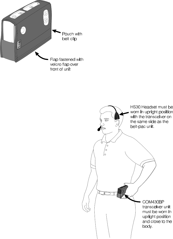
2. Wearing the COM430BP COMMUNICATOR®
Place the belt-pac transceiver unit
in its pouch and fasten the velcro
flap securely over the front of it as
shown in Figure 22. Squeeze
open the belt clip on the back of
the pouch and slide it over your
belt or waist band, either on your
right or left side.
The headset should be worn with
the transceiver side (the side
opposite the microphone) on the
same side as the belt-pac
transceiver. For best reception,
the belt-pac and headset should
both be worn in their upright
positions. Holding the earpiece,
rotate the headset microphone
so it is next to your mouth, as
shown in Figure 23.
14
Figure 24. Installing the COM430BP battery
Figure 25. Opening the COM430BP battery compartment
3. Charging the COM430BP Batteries
When a good battery is in the COMMUNICATOR transceiver and the power
®
is on, the yellow light on top of the unit will be lit. When the HS30 Headset
also has a good battery in it, and is on, the light on the belt-pac transceiver
unit will be red. This light indicates the power is on, and that there is a link
between the headset and belt-pac transceivers. It does not indicate how
much power is left in the batteries.
CAUTION: To prevent damage, turn Communicator OFF before
removing or installing batteries.
Installing and Removing COM430BP Batteries:
As a belt-pac transceiver battery weakens during routine use, you will hear
A repeating beep in the earpiece, indicating the battery needs to be
replaced. Typical Communicator battery life with normal use is 8 to 9 hours.
Install a fully charged battery in the battery compartment with the arrow on
the battery pointing outward, as shown in Figure 24. Slide it into the tracks
on both sides of the compartment until its catch clicks securely in place.
To remove the battery from a COM430BP belt-pac transceiver, slide the
battery latch open and push the battery in the direction of the large arrow
on the battery as shown in Figure 25.
15
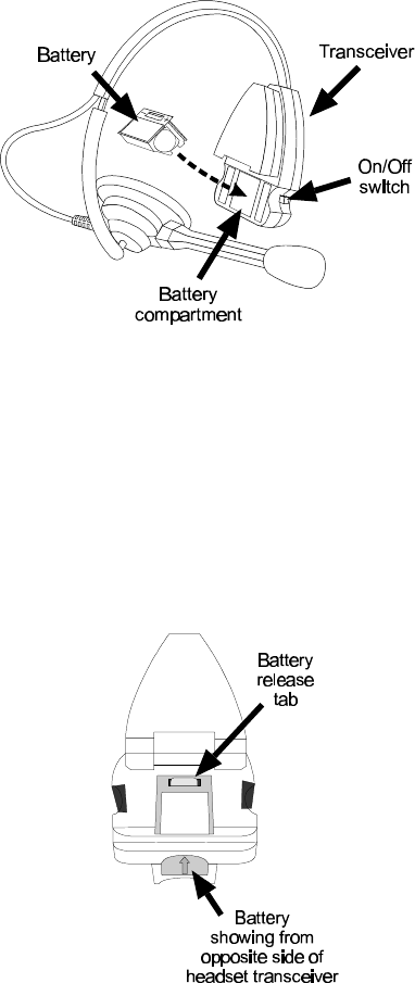
Figure 26. HS30 Headset
Figure 27. HS30 Headset transceiver
Installing and Removing HS30 Headset Batteries:
As a HS30 Headset battery weakens during routine use, you will hear a repeating
tone in the earpiece, indicating the battery in the transceiver needs to be replaced.
Typical HS30 battery life with normal use is 5 to 6 hours.
To install a fully charged battery in the HS30 Headset, insert the battery into the
battery compartment in the headset transceiver until its catch clicks securely in
place, as shown in Figure 26.
To remove the battery from a HS30 Headset, push the battery latch open and push
the battery from the opposite side of the headset transceiver, in the direction of the
arrow on the battery, as shown in Figure 27.
CAUTION: Turn headset OFF before removing batteries.
16
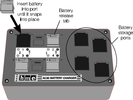
Figure 28. AC30 Battery Charger
Charging HS30 Batteries in the AC30 Battery Charger:
Place up to four HS30 batteries in the charger to charge at the same time, as
shown in Figure 28. A few seconds after each battery is placed in the charger,
the red CHARGING light on the panel adjacent to the battery will indicate the
battery charging status. See the CHARGING LIGHT STATUS TABLE for a
detailed explanation of what is happening. When a battery is fully charged, the
green READY light on the panel adjacent to it will light. (approximately 2.5
hours) It can then be placed back into a HS30 Headset.
CAUTION: Do not remove batteries from the charger until the green
READY light is lit, or the charger will reset and the charge
cycle will begin again.
17
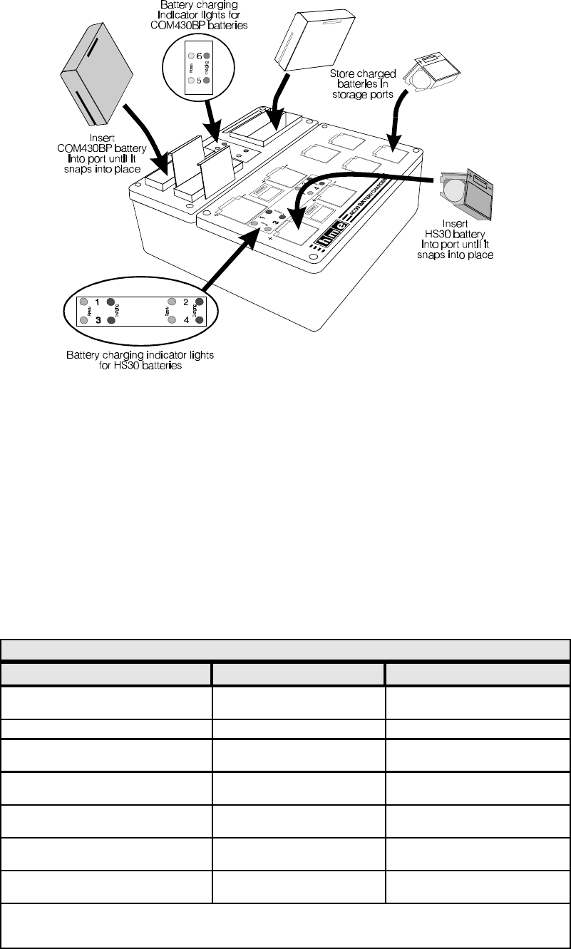
Figure 29. AC930 Battery Charger
Charging Batteries with the AC930 Battery Charger:
Place up to two COM430BP batteries and four HS30 batteries in the charger to charge at
the same time. A few seconds after each battery is placed in the charger, the red
CHARGING light on the panel adjacent to the battery, will indicate the battery charging
status. See the CHARGING LIGHT STATUS TABLE for a detailed explanation of what is
happening. When a battery is fully charged, the green READY light on the panel
adjacent to it will light. (approximately 4 hours for COM430BP batteries and 2.5
hours for HS30 batteries) It can then be placed back into a COMMUNICATOR .
®
CAUTION: Do not remove batteries from the charger until the green READY light is
lit, or the charger will reset and the charge cycle will begin again.
CHARGING LIGHT STATUS TABLE – WITH BATTERY INSERTED
RED CHARGING LIGHT WHAT IT MEANS WHAT TO DO
OFFOFF Charger doesn’t see theCharger doesn’t see the See NOTESee NOTE
batterybattery
STEADY ONSTEADY ON Battery is being chargedBattery is being charged Wait. Do not remove battery.Wait. Do not remove battery.
BLINKS: 2 seconds ON; 2 secondsBLINKS: 2 seconds ON; 2 seconds Battery is being discharged.Battery is being discharged. Wait. Do not remove battery.Wait. Do not remove battery.
OFFOFF
BLINKS: 2 times quick; 3 secondsBLINKS: 2 times quick; 3 seconds DISCHARGE ERRORDISCHARGE ERROR Battery is not dischargingBattery is not discharging
OFFOFF properly. See NOTE.properly. See NOTE.
BLINKS: 3 times quick; 3 secondsBLINKS: 3 times quick; 3 seconds CHARGING ERRORCHARGING ERROR Battery is not charging properly. Battery is not charging properly.
OFFOFF See NOTE.See NOTE.
BLINKS: 4 times quick; 2 secondsBLINKS: 4 times quick; 2 seconds LOW BATTERY ERRORLOW BATTERY ERROR See NOTE.See NOTE.
OFFOFF
BLINKS: 5 times quick; 2 secondsBLINKS: 5 times quick; 2 seconds CHARGING ERRORCHARGING ERROR See NOTE.See NOTE.
OFFOFF
NOTE: Either the battery or the charger has a problem. Mark the battery and retry in a different slot. The Either the battery or the charger has a problem. Mark the battery and retry in a different slot. The
battery is faulty if it has the same problem in a different slot AND a known-good battery passes in thebattery is faulty if it has the same problem in a different slot AND a known-good battery passes in the
same slots. The charger circuitry is faulty if a known-good BATTERY fails in the same slots.same slots. The charger circuitry is faulty if a known-good BATTERY fails in the same slots.

{ In some dual-lane operations, button “C” is used to switch between Lanes 1 and 2, while button “A” is used to talk to customers in either lane.
In some dual-lane operations, button “A” is used to talk to customers in Lane 1, and button “C” is used to talk to customers in Lane 2.
18
III. SYSTEM 400 OPERATION
A. COM400BP or COM430BP COMMUNICATOR Operation COM400CC COMMUNICATOR Operation
®
In single or dual drive-thru operations, Communicator button "A" is for communication with the customer, and button "B" is for To operate the Communicator, use the control buttons shown in Figure 3 as follows. In both single and dual drive-thru
communication with other crew members wearing Communicators. In dual drive-thru operations, the Communicator button "C" is used operations, Communicator button “A” is for communication with the customer, and button “B” is for communication with other
to change lanes. Button “C” has no function in single drive-thru operations. crew members wearing Communicators. In dual drive-thru operations, the “C” button is used to change lanes.
®
ACTION RESULT ACTION RESULT
Single
Drive-Thru
Lane
Full-Duplex
Operation
If you are using the Communicator latching feature: If you are using the Communicator latching feature:
Press and release button “A” to latch communication channel open Press and release button “A” to latch communication channel open
for speaking and listening to customer. The channel will unlatch, for speaking and listening to customer. The channel will unlatch,
ending communication with the customer, if; ending communication with the customer, if;
1. you press and release button “A” again, or 1. you press and release button “A” again, or
2. you press button “B” or 2. you press button “B” or
3. the customer drives away 3. the customer drives away
If you are not using the Communicator latching feature: If you are not using the Communicator latching feature:
Press and hold button “A” while speaking and listening to customer. Press and hold button “A” while speaking and listening to customer.
Release when transaction is completed. Release when transaction is completed.
Customer hears your voice and you hear customer's Customer hears your voice and you hear
voice (two-way conversation). Everyone wearing a
Communicator hears the communication. customer’s voice (two-way conversation). Everyone
wearing a Communicator will hear the conversation.
While customer is speaking, press the up ▲ or down ▼ arrow to While customer is speaking, press the up ▲ or down ▼ arrow to
adjust volume level. adjust volume level.
Beep tones of increasing/decreasing frequency are Beep tones of increasing/decreasing loudness are
heard in headset as volume level increases/ decreases.heard in headset as volume increases/ decreases.
Customer's voice becomes louder or softer. Customer’s voice becomes louder or softer.
Press and hold button ?B” to speak to other crew members wearing Other personnel wearing Communicators hear your voice Press and hold button “B” to speak to other crew members wearing Other personnel wearing Communicators hear your
Communicators. Release to listen. in their headsets. Communicators. Release to listen. voice in their headsets.
Single
Drive-Thru
Lane
Half-Duplex
Operation
Press and hold button ?A” while speaking to customer. Customer hears your voice. Everyone wearing a Press and hold button “A” while speaking to customer. Customer hears your voice.
Communicator hears the communication.
Release button "A" and listen to customer. Customer's voice is heard in headsets of everyone Release button “A” and listen to customer. Customer’s voice is heard in headsets of everyone
wearing a Communicator. wearing Communicators.
While customer is speaking, press the up ▲ or down ▼ arrow to While customer is speaking, press the up ▲ or down ▼ arrow to
adjust volume level. heard in headset as volume level increases/decreases.heard in headset as volume increases/ decreases.
Beep tones of increasing/decreasing frequency are Beep tones of increasing/decreasing loudness are
Customer's voice becomes louder or softer. Customer’s voice becomes louder or softer.
adjust volume level.
Press and hold button ?B” to speak to other crew members wearing Other personnel wearing Communicators hear your voice Press and hold button “B” to speak to other crew members wearing Other personnel wearing Communicators hear your
Communicators. Release to listen. in their headsets. Communicators. Release to listen. voice in their headsets.
Dual
Drive-Thru
Lane
Full-Duplex
Operation
If you are using the Communicator latching feature: If you are using the Communicator latching feature:
Press and release button “A” to latch communication Channel 1 open Press and release button “A” to latch communication Channel 1 open
for speaking and listening to customer in Lane 1. The channel will for speaking and listening to customer in Lane 1. The channel will
unlatch, ending communication with the customer, if; unlatch, ending communication with the customer, if;
1. you press and release button “A” again, or 1. you press and release button “A” again, or
2. you press button “B,” or 2. you press button “B,” or
3. you press button “C,” or 3. you press button “C,” or
4. the customer drives away 4. the customer drives away
If you are not using the Communicator latching feature: If you are not using the Communicator latching feature:
Press and hold button “A” while speaking and listening to customer Press and hold button “A” while speaking and listening to customer
in Lane 1 or 2. Release when transaction is completed. {in Lane 1 or 2. Release when transaction is completed. {
Customer hears your voice and you hear customer's Customer hears your voice and you hear
voice (two-way conversation). Everyone wearing a customer’s voice (two-way conversation). Everyone
Communicator hears the communication. wearing Communicators set to the same channel
NOTE: When transmitting in Lane 1 operation, the
Communicator power light will blink rapidly.
When transmitting in Lane 2 operation, the
Communicator power light will blink rapidly
4 times, then pause and repeat. Lanes 1 and
2 have different sounding vehicle-present
tones.
hears the communication.
While customer is speaking, press the up ▲ or down ▼ arrow to While customer is speaking, press the up ▲ or down ▼ arrow to
adjust volume level. adjust volume level.
Beep tones of increasing/decreasing frequency are Beep tones of increasing/decreasing loudness are
heard in headset as volume level increases/decreases. heard in headset as volume increases/ decreases.
Customer's voice becomes louder or softer. Customer’s voice becomes louder or softer.
Press button "C" to switch to the other lane. {You hear the customer’s voice from the other lane. Press button “C” to switch to Lane 2. {You hear customer’s voice from other lane.
Press and hold button ?B” to speak to other crew members wearing Other personnel wearing Communicators hear your voice Press and hold button “B” to speak to other crew members wearing Other personnel wearing Communicators hear your
Communicators. Release to listen. Communicators. Release to listen. voice in their headsets.
in their headsets.
Dual
Drive-Thru
Lane
Half-Duplex
Operation
Press and hold button ?A” while speaking to customer in Lane 1 or Customer hears your voice. Everyone wearing Press and hold button “A” while speaking to customer in Lane 2. {Customer hears your voice. Everyone wearing
2. {Communicators hears the communication. Communicators hears the communication.
Release button and listen to customer. Customer's voice is heard in headsets of everyone Release button and listen to customer. Customer’s voice is heard in headsets of everyone
wearing Communicators. wearing Communicators.
While customer is speaking, press the up ▲ or down ▼ arrow to While customer is speaking, press the up ▲ or down ▼ arrow to
adjust volume level. heard in headset as volume level increases/ decreases. heard in headset as volume increases/decreases.
Beep tones of increasing/decreasing frequency are Beep tones of increasing/decreasing loudness are
Customer's voice becomes louder or softer. Customer’s voice becomes louder or softer.
adjust volume level.
Press button "C" to switch to the other lane. {You hear the customer’s voice from the other lane. Press button “C” to switch to Lane 2. {You hear customer's voice from other lane.
Press and hold button ?B” to speak to other crew members wearing Other personnel wearing Communicators hear your voice Press and hold button “B” to speak to other crew members wearing Other personnel wearing Communicators hear your
Communicators. Release to listen. in their headsets. Communicators. Release to listen. voice in their headsets.
ACTION RESULT
To record
Message
#1
Press and release the RECORD MODE button
once on the System 400 base station.
The red MESSAGE RECORD light on the
System 400 base station will come on.
Press and hold button "B" on the
COMMUNICATOR ® and talk into the headset
microphone to record a message.
The MESSAGE RECORD light on the System
400 base station will begin blinking.
Release button "B." The record function will stop and the
MESSAGE RECORD light will go off.
To record
Message
#2
Press and release the RECORD MODE button
twice on the System 400 base station.
The green MESSAGE RECORD light on the
System 400 base station will come on.
Press and hold button "B" on the
Communicator and talk into the headset
microphone to record a message.
The MESSAGE RECORD light on the System
400 base station will begin blinking.
Release button "B." The record function will stop and the
MESSAGE RECORD light will go off.
» Unfold page 19
B. Speed-Team Drive-Thru Operation
Speed team operation is used during high-volume times. Placing the speed-team button on
the base station in the ON position will disable the speaker and microphone in the speaker
post or menu board, and disable the vehicle-alert tone. An order taker wearing a
Communicator relays orders from outside into the store using the “B” channel.
C. Remote Display Operation
One or more R30 Remote Displays may be used with your System 400. Each remote
display was set up by the installer to show the amount of time the current car has been at
the menu board, speaker post or service window. A remote display shows the time for one
location only. It begins counting when the car arrives and stops when the car leaves. The
remote displays will only display time. They will not store or record information.
D. Message Repeater Operation and Setup
To record messages on the System 400 internal message repeater, press the MESSAGE
REPEATER button IN on the base station and do the following.
After a new message has been recorded, or after the base station has lost and
regained power, any message to the menu board will always be heard in the
Communicator headset the first three times it plays.
To change the message repeater setup, locate and set the S8 and S10 DIP switches at
the bottom of the System 400 Base Station audio circuit board. Refer to the S8 AND S10
DIP SWITCH FUNCTIONS tables to the right for S8 and S10 switch functions.
If a System 30 Timer is installed with the System 400, the timer alert output can be used to
trigger tones in the headset or to cause a message to be played. Set S8 and/or S10,
switch #5 to OFF for an alert tone (triple beep), which will be heard only in headsets, or to
ON for recorded messages to be heard through selected speakers and headsets.
If a System 400 is installed without a System 30 Timer, set both S8 and S10 switches #5 to
OFF so the message repeater input will be triggered only by vehicle detector signals.
S8 AND S10 DIP SWITCH FUNCTIONS
Refer to Figure 30 on page 23 for DIP switch locations.
S8 — Switch Functions
Switch Function
1ON - Allow inbound audio while message #1 is playing
OFF - DO NOT allow inbound audio while message #1 is playing
2ON - Transmit message #1 to Communicators
OFF - DO NOT transmit message #1 to Communicators
3ON - Send message #1 to outside speaker
OFF - DO NOT send message #1 to outside speaker
4ON - Send message #1 to ceiling speaker
OFF - DO NOT send message #1 to ceiling speaker
5ON - Trigger message #1 from alert input
OFF - Trigger message #1 from vehicle present input
6ON - Vehicle present tone is high pitched
OFF - Vehicle present tone is low pitched
7ON - 3 second delay
OFF - No delay
8NOT USED
NOTE: In older equipment, S10 may not be present.
S10 — Switch Functions
Switch Function
1ON - Allow inbound audio while message #2 is playing
OFF - DO NOT allow inbound audio while message #2 is playing
2ON - Transmit message #2 to Communicators
OFF - DO NOT transmit message #2 to Communicators
3ON - Send message #2 to outside speaker
OFF - DO NOT send message #2 to outside speaker
4ON - Send message #2 to ceiling speaker
OFF - DO NOT send message #2 to ceiling speaker
5ON - Trigger message #2 from alert input
OFF - Trigger message #2 from vehicle present input
6NOT USED
7ON - 3 second delay
OFF - No delay
8NOT USED
NOTES:
Message #1 –
1. Will be triggered by a vehicle present signal if S8 switchs 5 is OFF. The playing
message can be cancelled by pressing the “A” button on the Communicator.
2. Will be triggered by an alert signal from the timer if S8 switch 5 is ON.
3. Will be played to the locations selected on S8 switches 2, 3 and 4. See page 23.
Message #2 –
1. Will be triggered by a vehicle present signal if S10 switchs 5 is OFF.
The playing message can be cancelled by pressing the “A” button on the
Communicator.
2. Will be triggered by an alert signal from the timer if S10 switch 5 is ON.
3. Will be played to the locations selected on S10 switches 2, 3 and 4. See page 23.
If S8 switch 5 and S10 switch 5 are both set to ON or OFF, Message #1 and
Message #2 will be played alternately.

20
IV. HOW TO CARE FOR THE EQUIPMENT
A. The COMMUNICATOR®
1. Proper Handling of Headset Cables and Connectors
HOW TOHOW TO and HOW NOT TOHOW NOT TO handle Headset Cables and Connectors
ALWAYS NEVER
Align the connector key and pins with key and holes Twist headset connector into Communicator
in the receptacle when plugging the headset into the receptacle.
Communicator.
Fasten cable to pouch with strain relief strap.
Clip the cable to your clothing with the clothing clips.
Grasp the connector to plug in or unplug the headset.
Use both hands to remove the headset from your head.
Use both hands to adjust the microphone position.
Handle the headset cable with care.
Carry and hang the headset by its metal headband.
Allow cable to be stressed at connector.
Allow cable to hang freely.
Grasp and pull cable to unplug headset.
Remove headset with only one hand.
Adjust microphone position with only one hand.
Pull, twist, bend or knot the headset cable.
Carry or hang the headset by its cable.
2. Cleaning the COMMUNICATOR®
The following cleaning procedure is recommended at least once each month.
!If the Communicator has a belt and/or pouch, remove it from the pouch.
Wash the belt and/or pouch in a washing machine with normal laundry detergent.
Dry them in a dryer or hang them up to dry.
!Remove the battery from the Communicator.
!Clean the Communicator with a damp sponge. Wet the sponge and wring it out
so it is damp, not dripping wet. Spray household cleaner on the sponge (NOT
DIRECTLY ON THE EQUIPMENT). Clean the Communicator with the sponge, and
dry it throughly.
!Clean the metal battery contacts on the battery with alcohol on a cotton swab. Wet
the tip of the swab with alcohol and squeeze the excess alcohol from it. Wipe
each contact with the swab, and be certain all the contacts are dry before installing
the batteries.
!Place the battery back in the Communicator and, if there is a pouch, place the
Communicator back in the pouch and fasten the strap securely over it.
!Clean the headset and cable with a damp sponge sprayed with houshold cleaner.
The foam muff on the headset earpiece is easily replaced for sanitary purposes.
To order extra foam muffs, call your local HME sales representative.
B. The Battery Charger
Avoid splashing water or grease on the battery charger. Clean the battery charger monthly
as follows:
CAUTION: Always unplug the battery charger before cleaning it.
!Remove all batteries from the battery charger.
!Clean the battery charger case with a damp sponge. Wet the sponge and wring it
out so it is damp, not dripping wet. Spray household cleaner on the sponge (NOT
DIRECTLY ON THE EQUIPMENT). Clean the battery charger with the sponge, and
dry it throughly.
!Wet the tip of a cotton swab with rubbing alcohol, and squeeze the excess alcohol
from the swab. Wipe the metal contacts inside each battery port with the damp
swab. Allow the contacts to dry before placing batteries in the ports.

21
V. IN CASE OF PROBLEMS (Refer to the circuit board illustration on page 23)
TROUBLESHOOTING CHECKLIST
Problem Probable Cause Solution
No sound in headset when Power is off at base station. Check circuit breaker for building.
you press
COMMUNICATOR button
®
"A" and speak into headset
microphone.
Power supply in base station is not Check power supply indicator lights
working. on base station. If any light is not lit,
be certain AC power adapter is
plugged into AC electrical outlet, and
connected to J2 connector on audio
circuit board in base station.
Communicator not turned on. Turn Communicator on by pushing
ON/OFF button. Be certain light goes
on.
Volume not set correctly. Push volume-control buttons to adjust
volume.
Headset connector not plugged in Plug headset connector firmly into
properly. (This applies only to Communicator receptacle.
COM400BP and COM400CC.)
Headset defective. Replace with another headset.
Low or dead battery. Check ON/POWER light. If not lit,
replace battery.
Communicator failed. Use another Communicator.
Call HME. *
COM430
Only HS30 Headset not turned on. Press ON/Off switch to turn headset on.
HS30 Headset battery is low or dead. Replace battery.
Communicator channel "A" or Communicator not turned ON. Turn Communicator on.
"B" functions not working. Dead or weak battery. Replace battery.
Communicator or base station Use another Communicator.
failure. Channel "A" or "B" light and Call HME. *
RECEIVE light on base station do not
light when Communicator button "A"
or "B" is pressed.
"C" button does not switch Switch setting on Communicator Check S1 switch on Communicator.
between channels in a dual- incorrect. Switch #9 should be ON.
lane drive-thru.
Outbound sound too low. Outbound volume set too low for Turn outside speaker volume control
environment. (R128 in base station) clockwise with
small standard (slotted) screwdriver
until level is satisfactory.
No outbound sound;
customer cannot hear
anything.
System may be set for speed-team Be certain SPEED TEAM button on
operation. See pages 1 and 19. base station is out (OFF).
Loose wires on base station circuit Check speaker wire connections on
board. switcher circuit board.
Defective speaker or base station. Call HME. *
* For assistance, call HME at 1-800-848-4468, or Fax 858-552-0172.

22
Problem Probable Cause Solution
No inbound sound from System may be set for speed-team Be certain SPEED TEAM button on
customer (in half-duplex operation. See pages 1 and 19. base station is out (OFF).
operation). Base station may be set for wrong Check S6 switch on base station
drive-thru mode (full or half-duplex). circuit board. Switch #1 should be
ON for full-duplex
OFF for half-duplex
Personnel hear static only in Transmitter antenna connection on Tighten transmitter antenna
headsets. base station is loose. connection. (the antenna on top, left
of base station.)
No power to base station. Check base station power adapter
connections.
Circuit board defective. Call HME. *
COM430
Only
Interference from nearby equipment. Person wearing Communicator
should move to different location.
Belt-pac and/or headset not properly Be certain belt-pac is securely
worn. clipped onto belt or waistband, close
to body, and both belt-pac unit and
headset are in upright positions.
Personnel hear customer in Receiver antenna connection on Tighten receiver antenna connection.
headsets or ceiling speaker, base station is loose. (the antenna on top, right of base
but cannot hear each other. station.)
Status lights are not lit. Circuit board Call HME. *
is defective.
Defective COMMUNICATOR or Call HME. *
®
headset.
No tone or sound in headset Power interruption has caused When no vehicle is in the drive-thru
or ceiling speaker when unbalanced detecting circuit. lane, press vehicle detector override
vehicle drives into drive-thru switch on base station to RESET
lane. position, then back to NORMAL
position.
System may be set for speed-team Be certain SPEED TEAM button on
operation. See pages 1 and 19. base station is out (OFF).
Connector may be loose. Check all connectors.
Call HME. *
Personnel cannot hear Loose wires on base station circuit Be certain wires are securely
outside customers in board connector. connected in base station.
headset or ceiling speaker. System may be set for speed-team Be certain SPEED TEAM button on
operation. See pages 1 and 19. base station is out (OFF).
Outside speaker or audio circuit Call HME. *
board has failed.
Communicator has Low battery. Replace battery.
intermittent sound. Defective headset cable. (This Use another headset. Call HME. *
applies only to COM400BP and
COM400CC.)
Headset does not become OVERRIDE/RESET, NORMAL switch Place switch in the NORMAL position.
silent after customer has on base station is in the
driven away. OVERRIDE/RESET position.
Vehicle detector is locked up. Press OVERRIDE/RESET switch
twice.
Battery charger not working. Charger not plugged in. Plug in battery charger.
If still not working, call HME. *
Can not record message. Message repeater not turned on. Turn message repeater on.
Message will not play.
* For assistance, call HME at 1-800-848-4468, or Fax 858-552-0172.
23
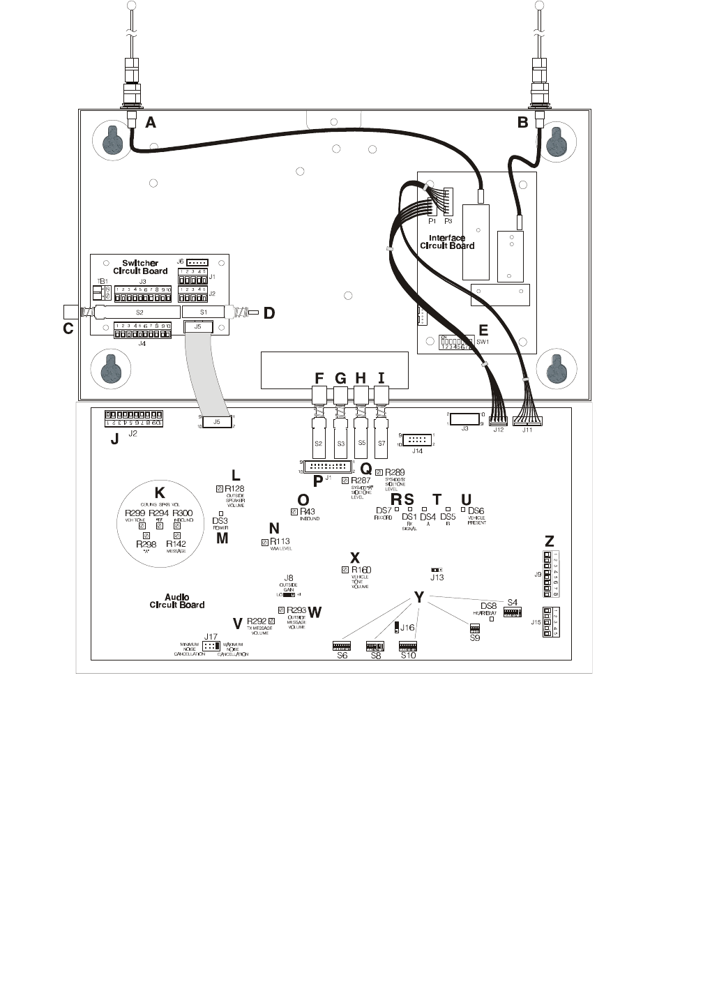
Figure 30. Base station circuit boards
A-Transmitter antenna connector N-VAA level control - R113
B-Receiver antenna connector O-Inbound volume control - R43
C-Wired backup system switch - S2 P-Automatic test equipment connector - J1
D-DM2 select switch - S1 Q-Channel “A” and “B” sidetone level controls - R287, R289
E-Frequency select switch - SW1 R-Message record LED - DS7
F-Record message switch - S2 S-Receiver LED - DS1
G-Message repeater ON/OFF switch - S3 T-Channel “A” and “B” LEDs - DS4, DS5
H-Speed team switch - S5 U-Vehicle present LED - DS6
I-Vehicle detector override switch - S7 V-Transmitter message volume control - R292
J-Power and ceiling speaker connector - J2 W-Outside message volume control - R293
K-Ceiling speaker volume controls - R142, X-Vehicle present tone volume control - R160
R294, R298, R299, R300
L-Outside speaker volume control - R128 Y-System configuration switches - S4, S6, S8, S9, S10
M - Power supply LED - DS3 Z-Base-to-base connector (for dual drive-thru operations) - J9
24
VI. SPECIFICATIONS
Base Station
1. Voltage input 16VAC ±2.5V
2. AC current input 350mA nominal, 1.4A maximum
3. Audio distortion <5% maximum level
4. Outside speaker output 3 watts RMS into 8 ohms
5. Ceiling speaker power 3 watts RMS into 8 ohms
6. Message repeater Message duration - 16 seconds
7. Controls/Switches 2-position vehicle detector switch
(Normal - Override/Reset)
2-position “Speed Team” ON/OFF switch
2-position “Message Repeater” ON/OFF switch
1-position “Record” switch
4-position RS485 bias/term switch
Outside speaker volume control
Outside speaker Hi-Lo volume jumper
Vehicle present tone level control
“A” sidetone
“B” sidetone
Inbound volume control
VAA level control
Ceiling speaker volume control
Vehicle present tone volume control
(3) 8-position DIP switches
4-position frequency select switch
Wireless/wired system select switch
Horn speaker/DM1 select switch
8. TX/RX Frequency FCC Part 90
9. Dimensions 8.2"H x 14.2"W x 3.5"D (208mm x 361mm x 89mm)
10. Weight 5.5 lbs (2.49kg) maximum
COM400CC COMMUNICATOR®
1. Battery (NiMH) 8 hours
2. RF Frequency Receive — FCC Part 90
Transmit — FCC Part 90
3. Dimensions 3d"H x 4c"W x 1½"D (86mm x 114mm x 38mm)
4. Weight 12 ounces (3.40kg) — including battery
5. Controls Buttons "A," "B" and "C"
Power control
Volume control
6. Indicator Red LED
Solid when receiving only.
Blinking when transmitter is activated, or
on secondary lane for dual-lane systems
7. Connector LT
25
COM400BP COMMUNICATOR®
1. Battery (NiCd) 8-10 hours
2. RF Frequency Receive — FCC Part 90
Transmit — FCC Part 90
3. Weight 11 ounces (3.12kg) — including battery
4. Controls Buttons "A," "B" and "C"
Power On/Off button
Volume control buttons
5. Indicator Red LED
Solid when receiving only
Blinking when transmitter is activated
6. Connector 5-pin DIN
COM430BP COMMUNICATOR®
1. Belt-pac Battery (NiCd) 8-10 hours
Headset Battery (NiMH) 5-6 hours
2. RF Frequency Receive — FCC Part 90
Transmit — FCC Part 90
3. Weight 11 ounces (3.12kg) — including battery
4. Controls Buttons "A," "B" and "C"
Power On/Off button
Volume control buttons
5. Indicator Red LED
Solid when receiving only
Blinking when transmitter is activated
AC30 Battery Charger (for HS30 Headset NiMH batteries)
1. Voltage input: 16.5VAC
2. Number of charge ports: 4
3. Charge time: 2-3 hours
4. Dimensions: 7.5"L x 4"W x 2¾”D (191mm x 102mm x 70mm)
5. Weight: 20.22 oz (.573Kg)
6. Indicators: Battery-charging (red) LEDs, 4 ea
Battery-ready (green) LEDs, 4 ea
AC420 Battery Charger (for COM400BP or COM430BP NiCd batteries)
1. Voltage input: 16.5VAC
2. Number of charge ports: 4
3. Charge time: 4-8 hours
4. Dimensions: 8"L x 12"W x 3.5"D (203mm x 305mm x 89mm)
5. Weight: 24 oz (.680Kg) - not including AC adapter
6. Indicators: Battery-charging (red) LEDs, 4 ea
Battery-ready (green) LEDs, 4 ea
26
AC900 Battery Charger (for COM400CC NiMH batteries)
1. Voltage input: 16.5VAC
2. Number of charge ports: 4
3. Charge time: 2 hours
4. Dimensions: 7.5"L x 4"W x 3 /D (191mm x 102mm x 78mm)
78
5. Weight: 23.04 oz (.653Kg)
6. Indicators: Battery-charging (red) LEDs, 4 ea
Battery-ready (green) LEDs, 4 ea
AC910 Battery Charger (for COM400BP NiCd and COM400CC NiMH batteries)
1. Voltage input: 16.5VAC
2. Number of charge ports: 4 for COM400CC NiMH batteries
2 for COM400BP NiCd batteries
3. Charge time: 2 hours for COM400CC NiMH batteries
4-8 hours for COM400BP NiCd batteries
4. Dimensions: 7.5"L x 7.5"W x 3 /D (191mm x 191mm x 78mm)
78
5. Weight: 31.94 oz (.906Kg)
6. Indicators: Battery-charging (red) LEDs, 6 ea
Battery-ready (green) LEDs, 6 ea
AC930 Battery Charger (for COM430BP NiCd and HS30 Headset NiMH batteries)
1. Voltage input: 16.5VAC
2. Number of charge ports: 4 for COM430 headset NiMH batteries
2 for COM400 belt-pac NiCd batteries
3. Charge time: 2-3 hours for COM430 headset NiMH batteries
4-8 hours for COM400BP belt-pac NiCd batteries
4. Dimensions: 7.5"L x 7.5"W x 3 /D (191mm x 191mm x 78mm)
78
5. Weight: 29.10 oz (.825Kg)
6. Indicators: Battery-charging (red) LEDs, 6 ea
Battery-ready (green) LEDs, 6 ea

27
VII. ACCESSORIES AND OPTIONAL EQUIPMENT
The following optional equipment is available for use with your System 400.
To order any of these products, call the HME Sales Department at (858) 535-6060.
Equipment Model Number
COMMUNICATOR COM400BP
®
COMMUNICATOR COM400CC
®
COMMUNICATOR COM430BP
®
Battery (NiCd) for COM400 or COM430BP COMMUNICATOR BAT400
®
Battery (NiMH) for HS30 BAT30
Battery (NiMH) for COM400CC BAT900
Headset for COM400BP HS9-90
Headset for COM400CC HS9LT
Headset for COM430BP HS30
Headset Earmuff no model number
Earpiece/Microphone HS4
Ultrasonic Vehicle Detector DU3
Vehicle Detector Board VDB101A
Vehicle Detector Loop (underground) VDL100
Message Repeater MR300
Remote Display R30
Ceiling Speaker MM100
Low-Profile Speaker with Volume Adjustment MM2500
Microphone DM1
Speaker SP2000A
Mode Switch (dual lane) MS1000
VIII. FCC NOTICE
HME wireless radio frequency systems are type-accepted in the United States under Part 90 of the
Federal Communications Commission (FCC) Code of Federal Regulations, and type-approved in
Canada by Industry and Science Canada. Because licensing depends on the system’s application,
it is the user’s responsibility to apply for a license from the FCC in the U.S. and its possessions, or
from Industry and Science Canada in Canada and its territories. Licensing requirements vary from
country to country. Contact your local licensing agency for specific requirements.
This device complies with Part 15 of the FCC rules. Operation is subject to the following two
conditions: (1) This device may not cause harmful interference, and (2) This device must accept any
interference received, including interference that may cause undesired operation.
NOTE: This equipment has been tested and found to comply with the limits for a Class A digital
device, pursuant to Part 15 of the FCC rules. These limits are designed to provide reasonable
protection against harmful interference when the equipment is operated in a commercial
environment. This equipment generates, uses and can radiate radio frequency energy and, if not
installed and used in accordance with the instruction manual, may cause harmful interference to
radio communication. Operation of this equipment in a residential area is likely to cause harmful
interference, in which case the user will be required to correct the interference at his own expense.
Changes or modifications not expressly approved by HM Electronics, Inc. could void the users
authority to operate this equipment.