HM Electronics COM6000BP Communicator 6000 User Manual 400519
HM Electronics Inc Communicator 6000 400519
UserManual.wiki
>
HM Electronics
>
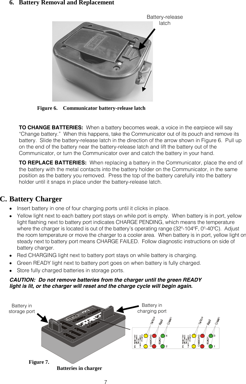
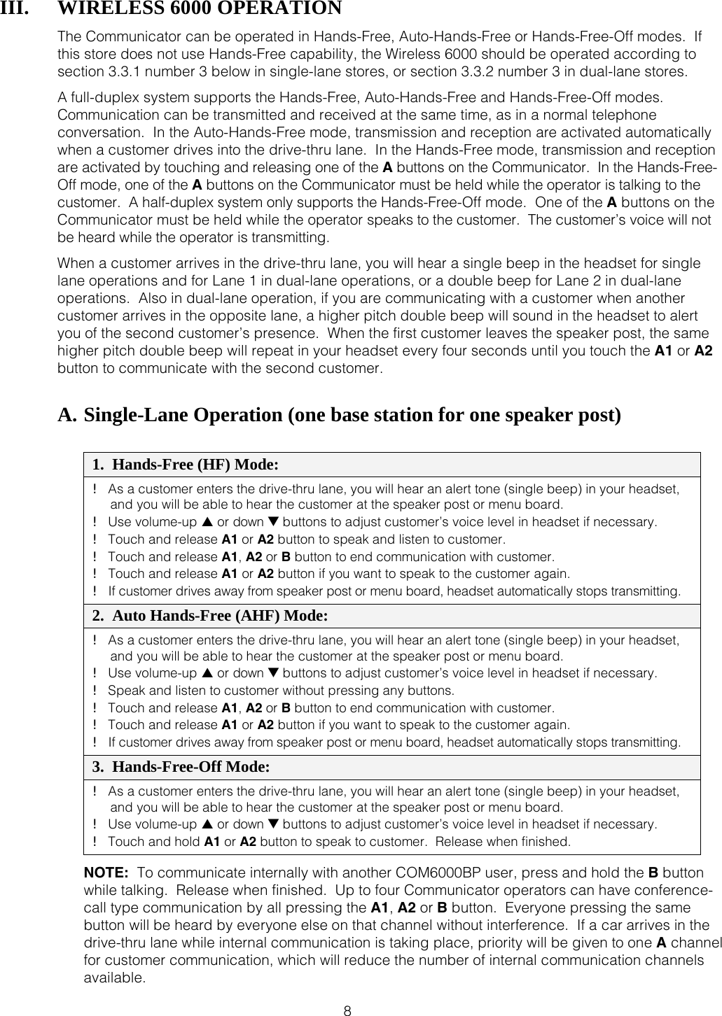
COM6000BP User Manual
User Manual
Navigation menu
Upload a User Manual
Namespaces
Wiki Guide
HTML
PDF
Info
Views
User Manual
Discussion / Help
Navigation