HOLYBRO HG-C05 Pixhawk 4 GPS module User Manual
HOLYBRO(H.K.) LIMITED Pixhawk 4 GPS module User Manual
HOLYBRO >
User_Manual
Pixhawk4 GPS
Manual
Overview
A Pixhawk4 GPS modules is designed with ublox NEO-M8 positioning module. It concurrent
GNSS receivers and can receive and track multiple GNSS systems (e.g. GPS, GLONASS, Galileo
and QZSS signals). Because of the dual-frequency RF front-end architecture, two of the three
signals can be received and processed concurrently. By default the GPS receivers are configured for
concurrent GPS (includes SBAS and QZSS) and GLONASS reception.
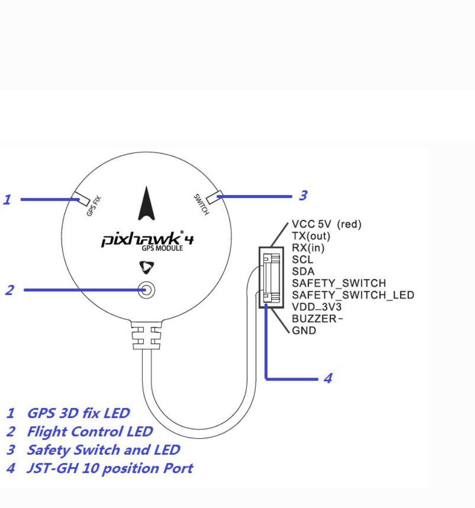
Port Description
GPS 3D fix LED
Flashing 1 time per second when the GPS module get a 3D position. When the GPS module loss
signal this LED will be off.
Flight Control LED
A 3-colors LED. It is controlled by flight controller via I2C bus.
Safety Switch and LED
Directly connect to flight controller. Push down the safety switch until the LED on before flying.
JST-GH 10 position port
Connect to GPS module port of flight controller.
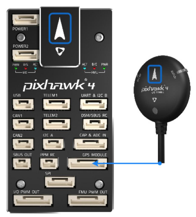
GPS + Compass + Buzzer + Safety Switch + LED
Attach the provided GPS with integrated compass, safety switch, buzzer and LED to the GPS
MODULEport.
The GPS/Compass should be mounted on the frame as far away from other electronics as possible,
with the direction marker towards the front of the vehicle (separating the compass from other
electronics will reduce interference).
Note:
The GPS module's integrated safety switch is enabled by default (when enabled, PX4 will not let
you arm the vehicle). To disable the safety press and hold the safety switch for 1 second. You can
press the safety switch again to enable safety and disarm the vehicle (this can be useful if, for
whatever reason, you are unable to disarm the vehicle from your remote control or ground
station).
FCC STATEMENT :
This device complies with Part 15 of the FCC Rules. Operation is subject to the following
two conditions:
(1) This device may not cause harmful interference, and
(2) This device must accept any interference received, including interference that may
cause undesired operation.
Warning: Changes or modifications not expressly approved by the party responsible for
compliance could void the user's authority to operate the equipment.
NOTE: This equipment has been tested and found to comply with the limits for a Class B
digital device, pursuant to Part 15 of the FCC Rules. These limits are designed to provide
reasonable protection against harmful interference in a residential installation. This
equipment generates uses and can radiate radio frequency energy and, if not installed
and used in accordance with the instructions, may cause harmful interference to radio
communications. However, there is no guarantee that interference will not occur in a
particular installation. If this equipment does cause harmful interference to radio or
television reception, which can be determined by turning the equipment off and on, the
user is encouraged to try to correct the interference by one or more of the following
measures:
Reorient or relocate the receiving an tenna.
Increase the separation between the equipment and receiver.
Connect the equipment into an outlet on a circuit different from that to which the
receiver is connected.
Consult the dealer or an experienced radio/TV technician for help.
FCC Radiation Exposure Statement:
This equipment complies with FCC radiation exposure limits set forth for an
uncontrolled environment. This equipment should be installed and operated
with minimum distance 20cm between the radiator & your body.