HON HAI PRECISION IND 74487504 802.11 b/g/n MiniPCI module User Manual Manual Part1
HON HAI Precision Ind. Co., Ltd. 802.11 b/g/n MiniPCI module Manual Part1
Contents
- 1. Manual Part1
- 2. Manual Part2
Manual Part1

Marvell. Moving Forward Faster
Doc. No. MV-S800473-00, Rev. B
August 14, 2007
CONFIDENTIAL
Document Classification: Proprietary Information
Cover
CB-82/MB-82/EC-82/MC-82
WLAN Client Cards
User Guide
74-4875-04
Cisco
Document Conventions
Note: Provides related information or information of special importance.
Caution: Indicates potential damage to hardware or software, or loss of data.
Warning: Indicates a risk of personal injury.
Document Status
Doc Status: 2.00 Technical Publication: 0.x
For more information, visit our website at: www.marvell.com
Disclaimer
No part of this document may be reproduced or transmitted in any form or by any means, electronic or mechanical, including photocopying and recording, for any purpose,
without the express written permission of Marvell. Marvell retains the right to make changes to this document at any time, without notice. Marvell makes no warranty of any
kind, expressed or implied, with regard to any information contained in this document, including, but not limited to, the implied warranties of merchantability or fitness for any
particular purpose. Further, Marvell does not warrant the accuracy or completeness of the information, text, graphics, or other items contained within this document.
Marvell products are not designed for use in life-support equipment or applications that would cause a life-threatening situation if any such products failed. Do not use
Marvell products in these types of equipment or applications.
With respect to the products described herein, the user or recipient, in the absence of appropriate U.S. government authorization, agrees:
1) Not to re-export or release any such information consisting of technology, software or source code controlled for national security reasons by the U.S. Export Control
Regulations ("EAR"), to a national of EAR Country Groups D:1 or E:2;
2) Not to export the direct product of such technology or such software, to EAR Country Groups D:1 or E:2, if such technology or software and direct products thereof are
controlled for national security reasons by the EAR; and,
3) In the case of technology controlled for national security reasons under the EAR where the direct product of the technology is a complete plant or component of a plant,
not to export to EAR Country Groups D:1 or E:2 the direct product of the plant or major component thereof, if such direct product is controlled for national security reasons
by the EAR, or is subject to controls under the U.S. Munitions List ("USML").
At all times hereunder, the recipient of any such information agrees that they shall be deemed to have manually signed this document in connection with their receipt of any
such information.
Copyright © 2007. Marvell International Ltd. All rights reserved. Marvell, the Marvell logo, Moving Forward Faster, Alaska, Fastwriter, Datacom Systems on Silicon, Libertas,
Link Street, NetGX, PHYAdvantage, Prestera, Raising The Technology Bar, The Technology Within, Virtual Cable Tester, and Yukon are registered trademarks of Marvell.
Ants, AnyVoltage, Discovery, DSP Switcher, Feroceon, GalNet, GalTis, Horizon, Marvell Makes It All Possible, RADLAN, UniMAC, and VCT are trademarks of Marvell. All
other trademarks are the property of their respective owners.
CB-82/MB-82/EC-82/MC-82
User Guide
Doc. No. MV-S800473-00 Rev. B CONFIDENTIAL Copyright © 2007 Marvell
Page 2 Document Classification: Proprietary Information August 14, 2007, 2.00

Table of Contents
Copyright © 2007 Marvell CONFIDENTIAL Doc. No. MV-S800473-00 Rev. B
August 14, 2007, 2.00 Document Classification: Proprietary Information Page 3
Table of Contents
Table of Contents .......................................................................................................................................3
List of Figures............................................................................................................................................. 5
List of Tables .............................................................................................................................................. 7
1 Introduction....................................................................................................................................9
1.1 Overview ...........................................................................................................................................................9
1.2 Wireless Networks ............................................................................................................................................9
1.2.1 Ad-Hoc Mode......................................................................................................................................9
1.2.2 Infrastructure Mode.............................................................................................................................9
2 Marvell Wireless Configuration Utility Overview...................................................................... 11
2.1 Overview .........................................................................................................................................................11
2.2 Marvell Wireless Configuration Utility..............................................................................................................11
2.2.1 Windows XP and Windows Server 2003 Users ................................................................................11
2.2.2 Tray Status Icons..............................................................................................................................12
2.3 Security ...........................................................................................................................................................13
3 Marvell Wireless Configuration Utility User Interface..............................................................15
3.1 Network Status Tab.........................................................................................................................................16
3.1.1 Select Profile.....................................................................................................................................16
3.1.2 Link Information ................................................................................................................................17
3.1.3 Signal Strength / Wireless Mode Indicator........................................................................................18
3.1.4 Internet Protocol (TCP/IP) ................................................................................................................18
3.1.5 Actual Throughput Performance.......................................................................................................19
3.1.6 Radio On/Off Check Box ..................................................................................................................19
3.2 Profile Manager Tab........................................................................................................................................21
3.2.1 Profile Setting—Network Info Tab ....................................................................................................22
3.2.2 Profile Setting—Security Tab............................................................................................................24
3.2.3 Legacy Authentication Modes...........................................................................................................25
3.2.3.1 Open System / Shared Key / Auto Switch..........................................................................26
3.2.3.2 WPA-PSK / WPA2-PSK .....................................................................................................28
3.2.4 802.1X Authentication Modes ...........................................................................................................29
3.2.4.1 802.1X / WPA / WPA2 with EAP/TLS.................................................................................29
3.2.4.2 802.1X / WPA / WPA2 with PEAP......................................................................................36
3.2.4.3 802.1X / WPA / WPA2 with EAP/TTLS...............................................................................41
3.2.4.4 802.1X / WPA / WPA2 with LEAP ......................................................................................46
3.2.4.5 802.1X / WPA / WPA2 with EAP-FAST..............................................................................49
3.2.5 Profile Setting—Protocol Tab ...........................................................................................................52

CB-82/MB-82/EC-82/MC-82
User Guide
Doc. No. MV-S800473-00 Rev. B CONFIDENTIAL Copyright © 2007 Marvell
Page 4 Document Classification: Proprietary Information August 14, 2007, 2.00
3.3 Site Survey Tab...............................................................................................................................................53
3.3.1 Site Survey—Networks Filter............................................................................................................53
3.3.2 Site Survey—List of Detected Stations.............................................................................................54
3.3.3 Site Survey—Filter Button ................................................................................................................55
3.3.3.1 Network SSID.....................................................................................................................55
3.3.3.2 Network BSSID ..................................................................................................................55
3.3.3.3 Select Channel ...................................................................................................................55
3.3.4 Site Survey—Refresh Button............................................................................................................55
3.3.5 Site Survey—Associate Button .........................................................................................................55
3.4 Statistics Tab...................................................................................................................................................56
3.4.1 Signal Strength .................................................................................................................................56
3.4.2 Transmit Section...............................................................................................................................57
3.4.3 Receive Section................................................................................................................................58
3.4.4 Protocol Section................................................................................................................................58
3.5 Advanced Tab .................................................................................................................................................59
3.5.1 Advanced Tab—Marvell Wireless Card............................................................................................59
3.5.2 Advanced Tab—Miscellaneous ........................................................................................................60
3.6 AutoLink Tab ...................................................................................................................................................60
3.7 Admin Tab.......................................................................................................................................................63
3.7.1 Admin Tab—Import Profiles..............................................................................................................63
3.7.2 Admin Tab—Export Profiles .............................................................................................................63
3.7.3 Admin Tab—Autostart Marvell Wireless Configuration Utility...........................................................64
3.7.4 Admin Tab—Stop Windows Wireless Zero Configuration Service ...................................................64
3.8 About Tab........................................................................................................................................................64
A Compliance Statements..............................................................................................................65
A.1 Federal Communications Commission (FCC) Compliance.............................................................................65
A.2 Industry Canada Notice...................................................................................................................................65
A.3 Europe—EU Declaration of Conformity and Restrictions................................................................................66
A.4 Taiwan DGT ....................................................................................................................................................67
B Acronyms and Abbreviations.....................................................................................................69
C Revision History ..........................................................................................................................71

List of Figures
Copyright © 2007 Marvell CONFIDENTIAL Doc. No. MV-S800473-00 Rev. B
August 14, 2007, 2.00 Document Classification: Proprietary Information Page 5
List of Figures
1 Introduction........................................................................................................................................ 9
2 Marvell Wireless Configuration Utility Overview .......................................................................... 11
Figure 1: Marvell Wireless Configuration Utility Icon........................................................................................11
Figure 2: Admin Tab—Stop Windows Wireless Zero Configuration Service ...................................................12
Figure 3: Tray Status Icons Window ................................................................................................................12
3 Marvell Wireless Configuration Utility User Interface .................................................................. 15
Figure 4: Network Status Tab ..........................................................................................................................16
Figure 5: Select Profile Section........................................................................................................................16
Figure 6: Link Information Section ...................................................................................................................17
Figure 7: Signal Strength Bar...........................................................................................................................18
Figure 8: Internet Protocol Section ..................................................................................................................18
Figure 9: Actual Throughput Performance Section..........................................................................................19
Figure 10: Radio On/Off Check Box ..................................................................................................................19
Figure 11: Radio On/Off in the System Tray ......................................................................................................20
Figure 12: Profile Manager Tab .........................................................................................................................21
Figure 13: Network Info Tab (Infrastructure Network)........................................................................................22
Figure 14: Network Info Tab (Ad-Hoc Network).................................................................................................23
Figure 15: Security Tab—Authentication Modes ...............................................................................................24
Figure 16: Security Tab—Open System with WEP............................................................................................26
Figure 17: WEP Key Configuration Window ......................................................................................................26
Figure 18: WEP Key Setting ..............................................................................................................................27
Figure 19: Security Tab—WPA2-PSK with TKIP ...............................................................................................28
Figure 20: Security Tab—WPA2 with EAP/TLS (Use Certificate)......................................................................29
Figure 21: EAP/TLS (Use Certificate) Configuration Window—Client Authentication Tab ................................30
Figure 22: Select Certificate Window (Client Certificates) .................................................................................31
Figure 23: EAP/TLS Configuration Window—Server Authentication Tab ..........................................................32
Figure 24: Select Certificate Window (Server Certificates) ................................................................................33
Figure 25: Server Authentication—Trusted Domain or Server...........................................................................34
Figure 26: Security Tab—WPA2 with PEAP ......................................................................................................36
Figure 27: PEAP Configuration Window—Client Authentication Tab ................................................................37
Figure 28: PEAP Configuration Window—Server Authentication Tab...............................................................38
Figure 29: Select Certificate Window (Server Certificates) ................................................................................39
Figure 30: Server Authentication—Trusted Domain or Server...........................................................................40
Figure 31: Security Tab—WPA2 with EAP/TTLS...............................................................................................41
Figure 32: EAP/TTLS Configuration Window—Client Authentication Tab .........................................................42
Figure 33: EAP/TTLS Configuration Window—Server Authentication Tab........................................................43
Figure 34: Select Certificate Window (Server Certificates) ................................................................................44
Figure 35: Server Authentication—Trusted Domain or Server...........................................................................45

CB-82/MB-82/EC-82/MC-82
User Guide
Doc. No. MV-S800473-00 Rev. B CONFIDENTIAL Copyright © 2007 Marvell
Page 6 Document Classification: Proprietary Information August 14, 2007, 2.00
Figure 36: Security Tab—WPA2 with LEAP ......................................................................................................46
Figure 37: LEAP Configuration Window ............................................................................................................47
Figure 38: Security Tab—WPA2 with EAP-FAST..............................................................................................49
Figure 39: EAP-FAST Configuration Window ....................................................................................................50
Figure 40: Protocol Tab .....................................................................................................................................52
Figure 41: Site Survey Tab ................................................................................................................................53
Figure 42: Site Survey—List of Detected Stations .............................................................................................54
Figure 43: Site Survey—Advanced Filter Window .............................................................................................55
Figure 44: Statistics Tab ....................................................................................................................................56
Figure 45: Transmit Section...............................................................................................................................57
Figure 46: Receive Section................................................................................................................................58
Figure 47: Protocol Section................................................................................................................................58
Figure 48: Advanced Tab...................................................................................................................................59
Figure 49: Miscellaneous Section ......................................................................................................................60
Figure 50: Access Point AutoLink Button...........................................................................................................60
Figure 51: AutoLink Tab.....................................................................................................................................61
Figure 52: AutoLink Tab (AutoLink Complete)...................................................................................................62
Figure 53: Admin Tab ........................................................................................................................................63
Figure 54: About Tab .........................................................................................................................................64
A Compliance Statements ...................................................................................................................65
B Acronyms and Abbreviations..........................................................................................................69
C Revision History ...............................................................................................................................71

CB-82/MB-82/EC-82/MC-82
User Guide
Doc. No. MV-S800473-00 Rev. B CONFIDENTIAL Copyright © 2007 Marvell
Page 7 Document Classification: Proprietary Information August 14, 2007, 2.00
THIS PAGE INTENTIONALLY LEFT BLANK
List of Tables
1 Introduction.........................................................................................................................................9
2 Marvell Wireless Configuration Utility Overview ........................................................................... 11
3 Marvell Wireless Configuration Utility User Interface ................................................................... 15
Table 1: Link Information Section Description ................................................................................................17
Table 2: Internet Protocol Section Description ...............................................................................................19
Table 3: Profile List Section Description .........................................................................................................21
Table 4: Network Info Tab Description ...........................................................................................................23
Table 5: WEP Key Configuration Window Description ...................................................................................27
Table 6: EAP/TLS Configuration Window Description—Client Authentication Tab ........................................34
Table 7: Select Certificate Window Description (Client Certificates) ..............................................................34
Table 8: EAP/TLS Configuration Window Description—Server Authentication Tab .......................................35
Table 9: Select Certificate Window Description (Server Certificates) .............................................................35
Table 10: PEAP Configuration Window Description—Client Authentication Tab .............................................40
Table 11: PEAP Configuration Window Description—Server Authentication Tab ............................................40
Table 12: Select Certificate Window Description (Server Certificates).............................................................41
Table 13: EAP/TTLS Configuration Window Description—Client Authentication Tab ......................................45
Table 14: EAP/TTLS Configuration Window Description—Server Authentication Tab.....................................45
Table 15: Select Certificate Window Description (Server Certificates).............................................................46
Table 16: LEAP Configuration Window Description .........................................................................................48
Table 17: EAP-FAST Configuration Window Description .................................................................................51
Table 18: Protocol Tab Description ..................................................................................................................52
Table 19: List of Detected Stations Description................................................................................................54
Table 20: Transmit Section Description............................................................................................................57
Table 21: Receive Section Description.............................................................................................................58
Table 22: Protocol Section Description.............................................................................................................59
Table 23: Advanced Tab Miscellaneous Section Description ...........................................................................60
A Compliance Statements ...................................................................................................................65
B Acronyms and Abbreviations..........................................................................................................69
Table 24: Acronyms and Abbreviations ............................................................................................................69
C Revision History ...............................................................................................................................71
Table 25: Revision History................................................................................................................................71

CB-82/MB-82/EC-82/MC-82
User Guide
Doc. No. MV-S800473-00 Rev. B CONFIDENTIAL Copyright © 2007 Marvell
Page 8 Document Classification: Proprietary Information August 14, 2007, 2.00
THIS PAGE INTENTIONALLY LEFT BLANK
Introduction
Overview
Copyright © 2007 Marvell CONFIDENTIAL Doc. No. MV-S800473-00 Rev. B
August 14, 2007, 2.00 Document Classification: Proprietary Information Page 9
1 Introduction
1.1 Overview
This document describes the functions of the Marvell Wireless Client Card Configuration Utility for
the following Marvell® IEEE 802.11g/b and draft-802.11n WLAN client cards:
Marvell CB-82 CardBus WLAN Client Card
Marvell MB-82 Mini PCI WLAN Client Card
Marvell EC-82 PCI Express WLAN Client Card
Marvell MC-82 PCI Express WLAN Client Mini Card
Marvell high throughput client cards are both IEEE 802.11g/b and draft-802.11n compliant.
1.2 Wireless Networks
The Marvell client cards operate similar to Ethernet cards, except that a radio replaces the wires
between communication devices. All existing applications that operate over Ethernet operate over a
Marvell wireless network without any modification or need for special wireless networking software.
The Marvell client cards support the following network technologies:
Ad-Hoc (peer-to-peer group) mode
Access Point (AP) Infrastructure mode
1.2.1 Ad-Hoc Mode
In Ad-Hoc mode (also referred to as peer-to-peer mode), wireless clients send and receive
information to other wireless clients without using an AP. In comparison to Infrastructure mode, this
type of WLAN connection only contains wireless clients. Ad-Hoc mode is useful for establishing a
network where wireless infrastructure does not exist or where services are not required. Two or
more computers can establish an Ad-Hoc network when within range of one another.
Ad-Hoc mode is used to connect network computers at home or in small offices. It can also be used
to set up a temporary wireless network for meetings.
1.2.2 Infrastructure Mode
In Infrastructure mode, wireless devices communicate with other wireless devices or devices on the
LAN side wired network through APs. When communicating through wired networks, client cards
send and receive information through APs.
Access Points are typically strategically located within an area to provide optimal coverage for
wireless clients. A large WLAN uses multiple APs to provide coverage over a wide area. APs
connect to a LAN through a wired Ethernet connection. APs send and receive information from the
LAN through this wired connection. Most corporate WLANs operate in Infrastructure mode because
they require access to the wired LAN in order to use services such as file servers or printers.
Note
For information on installing the Marvell Wireless Configuration Utility, the Marvell
client card, and the Marvell Windows driver, see the CB-82/MB-82/EC-82/MC-82
Installation Guide.
For a list of acronyms used throughout this document see Appendix B, Acronyms
and Abbreviations, on page 69.

CB-82/MB-82/EC-82/MC-82
User Guide
Doc. No. MV-S800473-00 Rev. B CONFIDENTIAL Copyright © 2007 Marvell
Page 10 Document Classification: Proprietary Information August 14, 2007, 2.00
THIS PAGE INTENTIONALLY LEFT BLANK
Marvell Wireless Configuration Utility Overview
Overview
Copyright © 2007 Marvell CONFIDENTIAL Doc. No. MV-S800473-00 Rev. B
August 14, 2007, 2.00 Document Classification: Proprietary Information Page 11
2Marvell Wireless Configuration Utility
Overview
2.1 Overview
The Marvell Wireless Client Card Configuration Utility is a Windows® based application that allows
configuration and management of the Marvell high throughput client cards. The Marvell Wireless
Configuration Utility sets up profiles and performs other wireless network management tasks. For
information on installing the Marvell Wireless Configuration Utility see the Installation Guide.
2.2 Marvell Wireless Configuration Utility
Once installed, the Marvell Wireless Configuration Utility is accessed from the Start menu or from
the Desktop.
Start menu:
Start > Marvell Wireless Configuration Utility
Start > Programs > Marvell > Marvell Wireless Configuration Utility
Desktop:
Double-click the Marvell Wireless Configuration Utility icon.
2.2.1 Windows XP and Windows Server 2003 Users
For Windows XP and Windows Server 2003, either the Windows Wireless Zero Configuration
Service or the Marvell Wireless Configuration Utility can be used to configure the Marvell client card.
For further information on the Windows Wireless Configuration Service, refer to the Windows
documentation.
Disabling Windows Wireless Zero Configuration Service
To disable the Windows Wireless Zero Configuration Service:
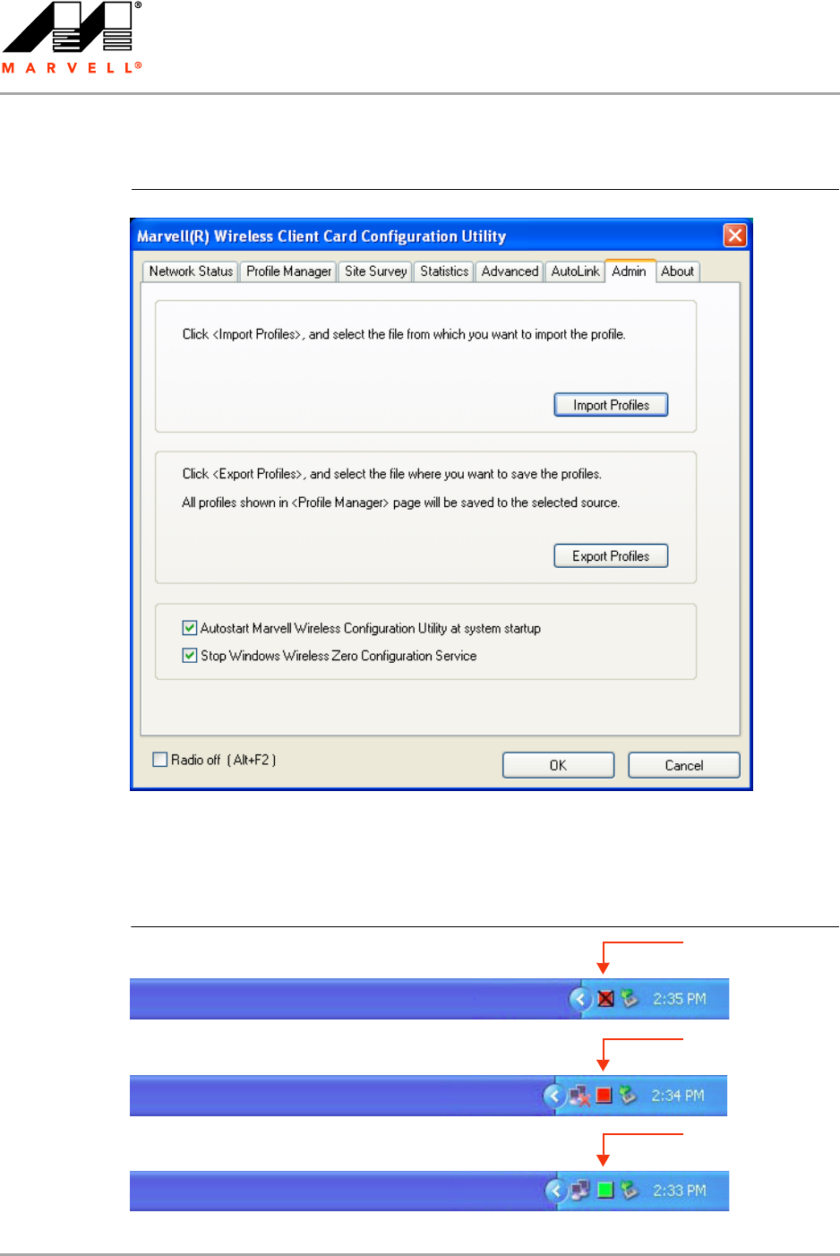
1. Start the Marvell Wireless Configuration Utility.
2. Click the Admin tab.
Figure 1: Marvell Wireless Configuration Utility Icon
Note
When using the Marvell Wireless Configuration Utility, Marvell recommends turning off
the Windows Wireless Zero Configuration Service, which is enabled by default. Both
utilities should not be used at the same time.
CB-82/MB-82/EC-82/MC-82
User Guide
Doc. No. MV-S800473-00 Rev. B CONFIDENTIAL Copyright © 2007 Marvell
Page 12 Document Classification: Proprietary Information August 14, 2007, 2.00
3. Select the Stop Windows Wireless Zero Configuration Service check box.
2.2.2 Tray Status Icons
Different icons in the system tray indicate the status of the wireless connection.
Figure 3: Tray Status Icons Window
Figure 2: Admin Tab—Stop Windows Wireless Zero Configuration Service
Card Unplugged
Connected
Not Connected
(red with “X” mark)
(red)
(green)

Marvell Wireless Configuration Utility Overview
Security
Copyright © 2007 Marvell CONFIDENTIAL Doc. No. MV-S800473-00 Rev. B
August 14, 2007, 2.00 Document Classification: Proprietary Information Page 13
2.3 Security
Implementing a security infrastructure to monitor physical access to WLAN networks is more difficult
than monitoring access on wired networks. Unlike wired networks where a physical connection is
required, anyone within the range of a wireless AP can send and receive frames, as well as listen for
frames being sent.
IEEE 802.11 and IEEE 802.1X define a set of standards and protocols for use in minimizing the
security risks on wireless networks. These include the authentication modes used to authenticate
the wireless client station and the wireless AP to be connected, complemented by different
encryption methods used for data to be transmitted over the wireless network. Four of these security
standards are as follows:
802.1X—802.1X authentication provides authenticated access to 802.11 wireless networks and
to wired Ethernet networks. 802.1X minimizes wireless network security risks by providing user
and computer identification, centralized authentication, and encryption services based on the
Wired Equivalent Privacy (WEP) algorithm. 802.1X supports the Extensible Authentication
Protocol (EAP). EAP allows the use of different authentication methods, such as smart cards
and certificates.
Wired Equivalent Privacy (WEP)—WEP is a basic security implementation according to the
IEEE 802.11 standard. Due to various security issues WEP encryption is vulnerable and was
therefore superseded by WPA and WPA2 encryption.
Wi-Fi Protected Access (WPA)—WPA is a security implementation based on a subset of the
802.11i standard. WPA provides enhanced security for wireless networks when used with the
Temporal Key Integrity Protocol (TKIP) and the Message Integrity Check (MIC) algorithms.
Wi-Fi Protected Access 2 (WPA2)—WPA2 is the next generation Wi-Fi security, based on the
final 802.11i standard. WPA2 offers the strongest available security in the form of Advanced
Encryption Standard (AES) level encryption, plus faster roaming between APs.
Security Configurations
The Marvell Wireless Configuration Utility supports the following security features:
Authentication Modes
•Open System
•Shared Key
•Auto Switch
•WPA-PSK
•WPA2-PSK
•WPA
•WPA2
•802.1X Authentication Protocol (including support for Cisco® Compatible Extensions (CCX))
- EAP/Transport Layer Security (EAP/TLS) (equivalent to Microsoft “Smart Card or other
Certificate”)
- Protected EAP (PEAP)
- EAP/Tunneled TLS Authentication Protocol (EAP/TTLS)
- Light EAP (LEAP)
- EAP-Flexible Authentication via Secure Tunneling (EAP-FAST)
Encryption Methods
•Security Off
•WEP (including support for Cisco Message Integrity Check (CMIC) and Cisco Key Integrity
Protocol (CKIP))

CB-82/MB-82/EC-82/MC-82
User Guide
Doc. No. MV-S800473-00 Rev. B CONFIDENTIAL Copyright © 2007 Marvell
Page 14 Document Classification: Proprietary Information August 14, 2007, 2.00
•TKIP (WPA, WPA-PSK)
•AES (WPA2, WPA2-PSK)
WEP Key Size
•40-bit key (64-bit WEP)
•104-bit key (128-bit WEP)

Marvell Wireless Configuration Utility User Interface
Copyright © 2007 Marvell CONFIDENTIAL Doc. No. MV-S800473-00 Rev. B
August 14, 2007, 2.00 Document Classification: Proprietary Information Page 15
3 Marvell Wireless Configuration Utility
User Interface
The Marvell Wireless Client Card Configuration Utility allows configuration of Marvell high
throughput client cards through the following tabs:
Network Status—displays the status of the network to which the user is connected. The
Marvell Wireless Configuration Utility initializes on this page.
Profile Manager—displays the current profiles and allows the user to set attributes for network
type, security options and protocols, as well as create/modify/delete profiles.
Site Survey—displays site survey information.
Statistics—displays the statistics of the current session.
Advanced—used to set protocol parameters.
AutoLink—to set AutoLink connection
Admin—used to import and export profiles. Additionally, the user can define how to use the
Marvell Wireless Configuration Utility and the Windows Wireless Zero Configuration Service.
About—provides information such as the driver version number, firmware version number,
Marvell Wireless Configuration Utility version number, and Medium Access Controller (MAC)
address of the client card.
CB-82/MB-82/EC-82/MC-82
User Guide
Doc. No. MV-S800473-00 Rev. B CONFIDENTIAL Copyright © 2007 Marvell
Page 16 Document Classification: Proprietary Information August 14, 2007, 2.00
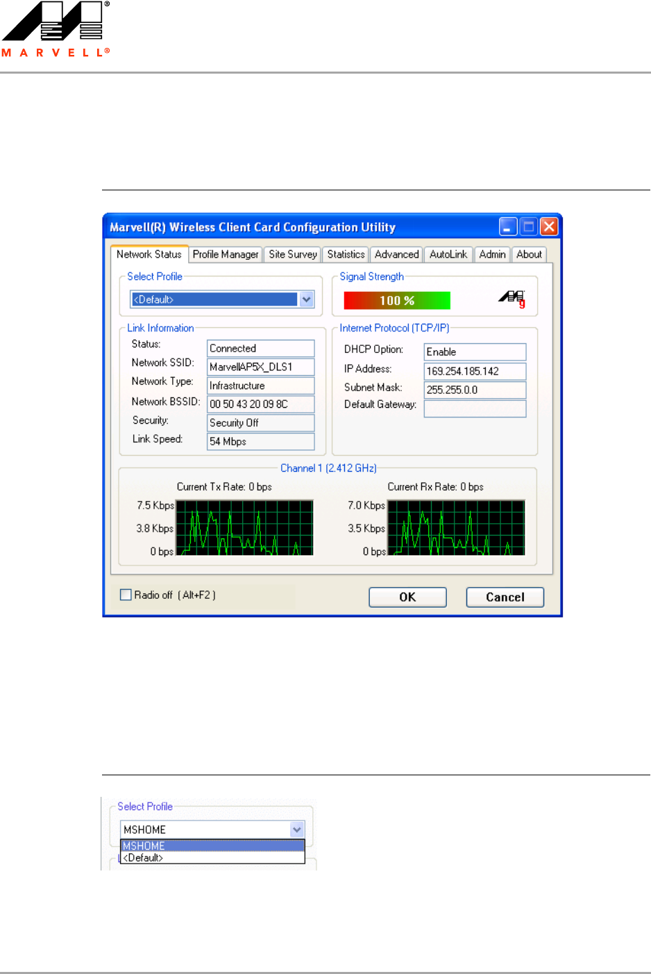
3.1 Network Status Tab
The Network Status tab displays the status of the network. When the Marvell Wireless
Configuration Utility initializes, it displays the Network Status tab.
3.1.1 Select Profile
The Select Profile section displays the name of the profile in use. Additional information about the
profile is provided in the Profile Manager.
Select one of the profiles previously defined by clicking the down arrow and highlighting a profile
from the pull-down list.
Profiles are created, modified, and deleted through the Profile Manager.
Figure 4: Network Status Tab
Figure 5: Select Profile Section
Marvell Wireless Configuration Utility User Interface
Network Status Tab
Copyright © 2007 Marvell CONFIDENTIAL Doc. No. MV-S800473-00 Rev. B
August 14, 2007, 2.00 Document Classification: Proprietary Information Page 17
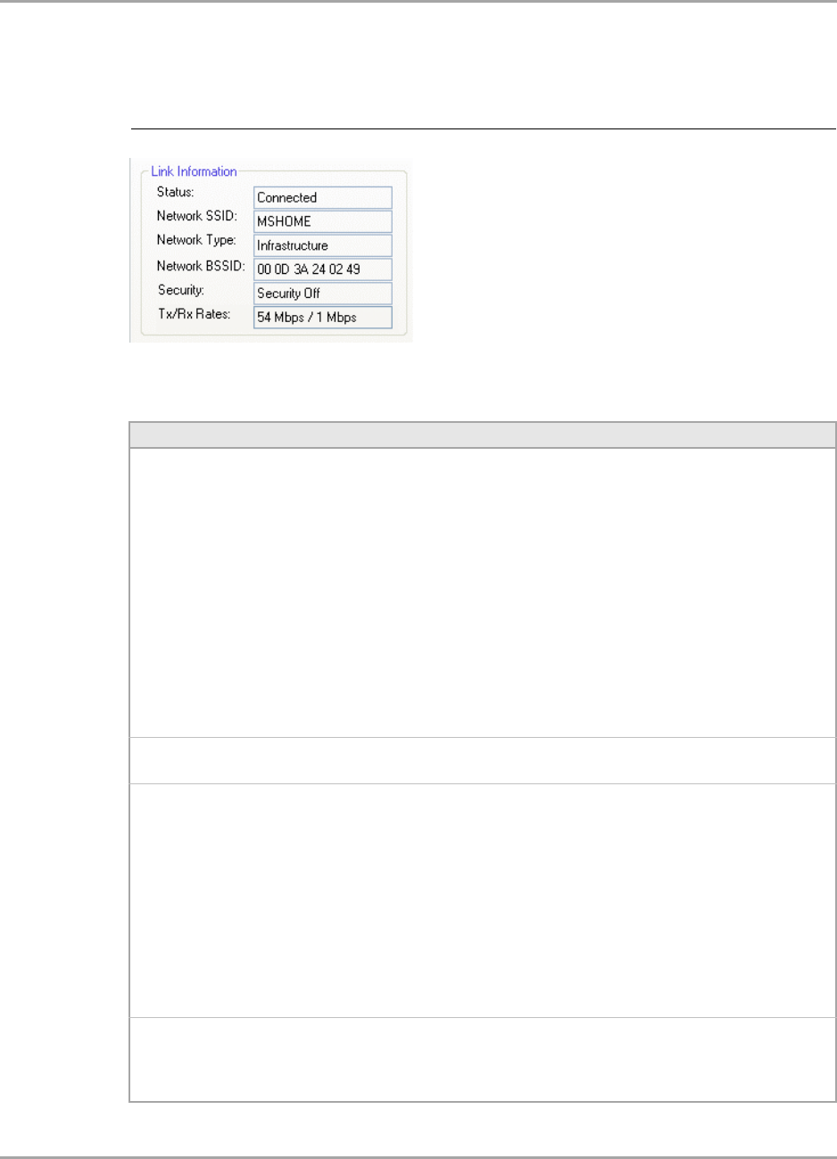
3.1.2 Link Information
The Link Information section contains the current information about the wireless connection.
Figure 6: Link Information Section
Table 1: Link Information Section Description
Field Description
Status Status of the wireless network connection:
•Card Unplugged
Client card is not plugged in, or client card is plugged in but not recognized.
•Connected
Client card is plugged in and connected to a wireless network.
•No Connection
Client card is plugged in, but no wireless connection.
•No Radio
Client card is plugged in, but the radio is turned off. To turn the radio on, clear
the Radio Off check box.
•Scanning for
Scanning for available APs and wireless stations in the area.
•Waiting for peer
Waiting for a peer station to connect to the wireless network (Ad-Hoc network
only).
Network SSID Network SSID label (i.e., Network Name). The Network Name is a text string of up
to 32 characters.
Network Type Type of environment connected to:
•Infrastructure Mode
In this mode, wireless clients send and receive information through APs. The
APs are strategically located within an area to provide optimal coverage for
wireless clients. A large WLAN uses multiple APs to provide coverage over a
wide area. APs can connect to a LAN through a wired Ethernet connection. APs
send and receive information from the LAN through the wired connection.
•Ad-Hoc Mode
In this mode, wireless clients send and receive information to other wireless
clients without using an AP. This type of WLAN only contains wireless clients.
Use Ad-Hoc mode to connect network computers at home or in small office, or
to set up a temporary wireless network for a meeting.
Network BSSID Network Basic Service Set (BSS) Identifier. The BSSID is a 48-bit identity used to
identify a particular BSS within an area. In Infrastructure BSS networks, the BSSID
is the MAC address of the AP. In Ad-Hoc networks, the BSSID is generated
randomly.
CB-82/MB-82/EC-82/MC-82
User Guide
Doc. No. MV-S800473-00 Rev. B CONFIDENTIAL Copyright © 2007 Marvell
Page 18 Document Classification: Proprietary Information August 14, 2007, 2.00
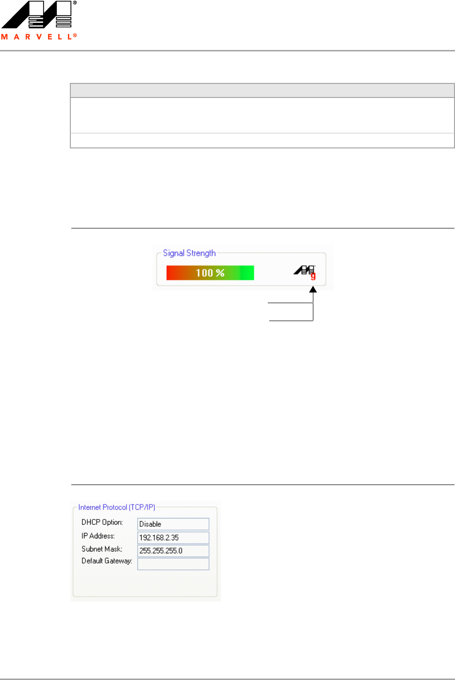
3.1.3 Signal Strength / Wireless Mode Indicator
The color-coded Signal Strength bar displays the signal strength of the last packet received by the
client card.
Signal strength is reported as a percentage. A signal in the red indicates a bad connection. A signal
in the green indicates a good connection.
The Wireless Mode indicator shows the data rates the client card operates. There are two modes:
802.11b
802.11g (backward compatible to 802.11b)
3.1.4 Internet Protocol (TCP/IP)
This section specifies the IP configuration of the client station when it is connected.
Security Reports the type and level of security set. The security level is set through the
Profile Setting of the Profile Manager tab. Configure security settings also
through the Site Survey tab when connecting to a network.
Tx/Rx Rates Current Tx Rate and Rx Rate of the channel being monitored.
Table 1: Link Information Section Description (Continued)
Field Description
Figure 7: Signal Strength Bar
g means connected to an 802.11g capable AP
b means connected to an 802.11b capable AP
Figure 8: Internet Protocol Section
Marvell Wireless Configuration Utility User Interface
Network Status Tab
Copyright © 2007 Marvell CONFIDENTIAL Doc. No. MV-S800473-00 Rev. B
August 14, 2007, 2.00 Document Classification: Proprietary Information Page 19
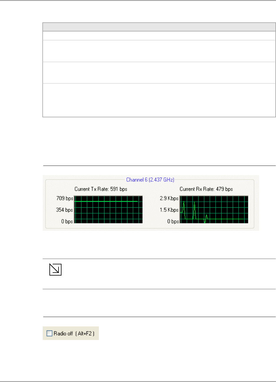
3.1.5 Actual Throughput Performance
This section of the Network Status tab displays the Current Tx Rate and the Current Rx Rate of the
channel being monitored.
3.1.6 Radio On/Off Check Box
Selecting the Radio Off check box turns off the radio. Clearing the check box turns on the radio.
Table 2: Internet Protocol Section Description
Field Description
DHCP Option Dynamic Host Configuration Protocol. Either enabled or disabled.
IP Address An identifier for a computer or device on a TCP/IP network. The format of
an IP address is a 32-bit numeric address written as four numbers
separated by periods. Each number can be 0 to 255.
Subnet Mask A mask used to determine what subnet an IP address belongs to. An IP
address has two components, the network part and the host part. The
subnet mask specifies the network part of the IP address.
Default Gateway The default node on a network that serves as an entrance to another
network. In enterprises, the gateway is the computer that routes the traffic
from a workstation to the outside network that is serving the Web pages.
In homes, the gateway is the Internet Service Provider (ISP) that connects
the user to the Internet.
Figure 9: Actual Throughput Performance Section
Note
These are actual throughput diagrams (without the WLAN overhead delivered by the
client card).
Figure 10: Radio On/Off Check Box

CB-82/MB-82/EC-82/MC-82
User Guide
Doc. No. MV-S800473-00 Rev. B CONFIDENTIAL Copyright © 2007 Marvell
Page 20 Document Classification: Proprietary Information August 14, 2007, 2.00
Another way to turn the radio on or off is to right-click the Configuration Utility icon in System Tray
and select Turn Radio Off to turn the radio off. When the radio is off, select Turn Radio On to turn
the radio back on.
The system hot key Alt+F2 can also be used to turn the radio on/off.
When the radio is off, there is no radio activity, and the following tabs are disabled:
Profile Manager
Site Survey
Statistics
Advanced
AutoLink
Figure 11: Radio On/Off in the System Tray
Marvell Wireless Configuration Utility User Interface
Profile Manager Tab
Copyright © 2007 Marvell CONFIDENTIAL Doc. No. MV-S800473-00 Rev. B
August 14, 2007, 2.00 Document Classification: Proprietary Information Page 21
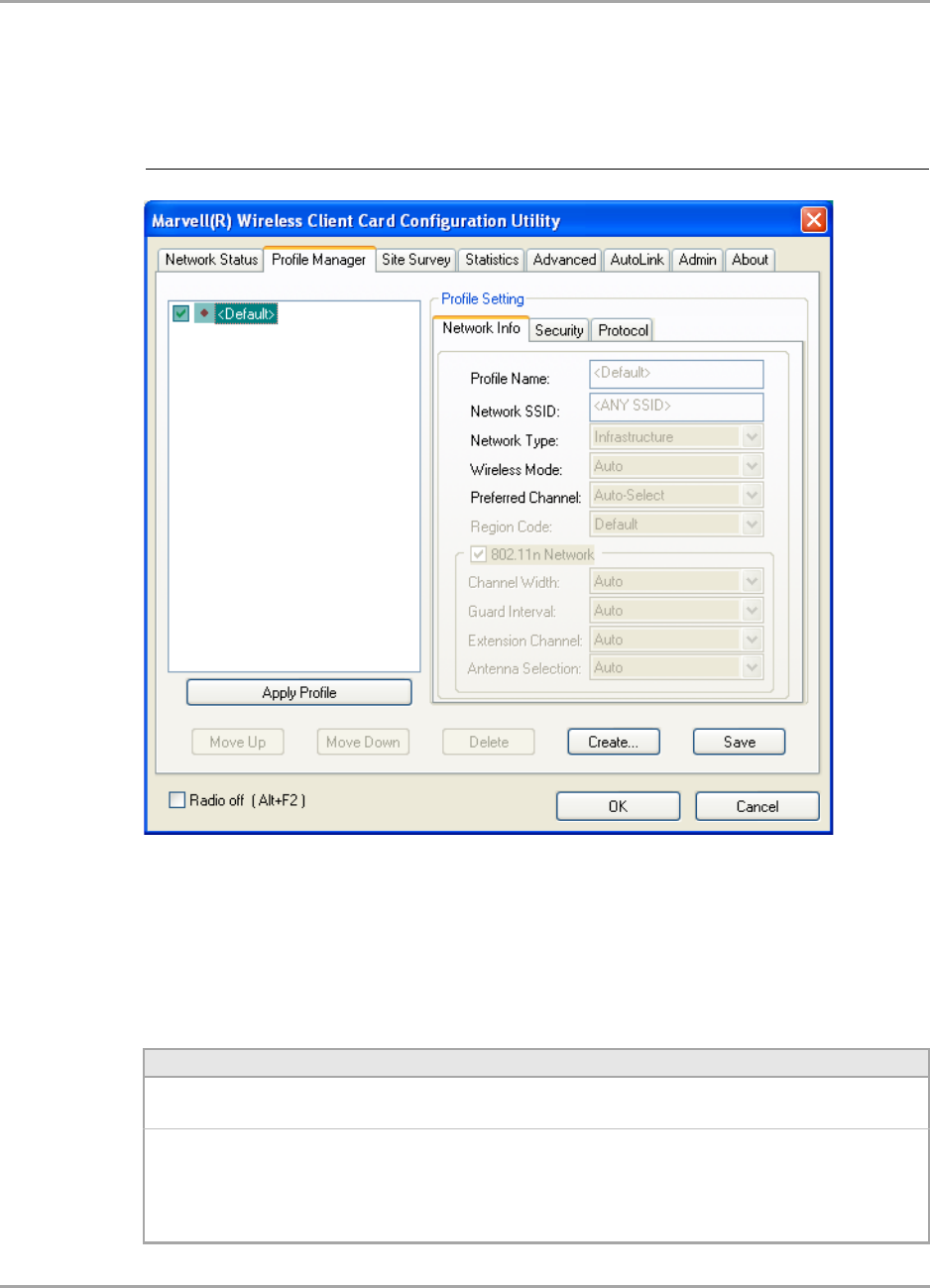
3.2 Profile Manager Tab
The Profile Manager tab displays the profiles available and allows you to create, modify, and delete
profiles.
Profile Manager—Profile List
The section on the left side of this tab lists all of the profiles available. Highlighting a profile selects it.
If the check box next to the profile is selected, that profile is used in auto-configuration mode when
the link is lost. If it is not selected, that profile is excluded in auto-configuration. The buttons
associated with this window are as follows.
Figure 12: Profile Manager Tab
Table 3: Profile List Section Description
Button Description
Apply Profile Applies the profile selected.
Apply the profile by double-clicking the desired profile.
Move Up/Down Moves the profile up and down in the list.
All profiles with the Network Type set to Infrastructure are displayed before the
profiles with the Network Type set to Ad-Hoc. In auto-configuration mode, the
selected profiles at the top of the list have higher priority than selected profiles at
the bottom of the list.
CB-82/MB-82/EC-82/MC-82
User Guide
Doc. No. MV-S800473-00 Rev. B CONFIDENTIAL Copyright © 2007 Marvell
Page 22 Document Classification: Proprietary Information August 14, 2007, 2.00
Profile Manager—Profile Setting
The Profile Settings are used to set, modify, and display information about the profile selected in the
Profile List section. The information is divided into three tabs:
Network Info
Security
Protocol
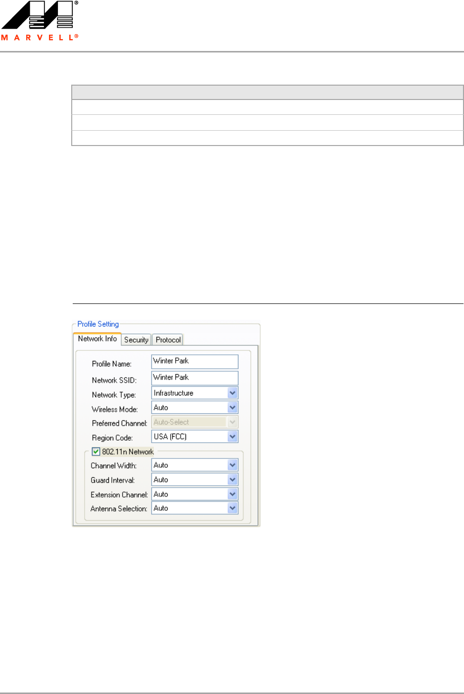
3.2.1 Profile Setting—Network Info Tab
The Profile Manager initially displays the Network Info tab.
Delete Deletes a profile.
Create Creates a profile.
Save Saves changes made to a selected profile.
Table 3: Profile List Section Description (Continued)
Button Description
Figure 13: Network Info Tab (Infrastructure Network)
Marvell Wireless Configuration Utility User Interface
Profile Manager Tab
Copyright © 2007 Marvell CONFIDENTIAL Doc. No. MV-S800473-00 Rev. B
August 14, 2007, 2.00 Document Classification: Proprietary Information Page 23
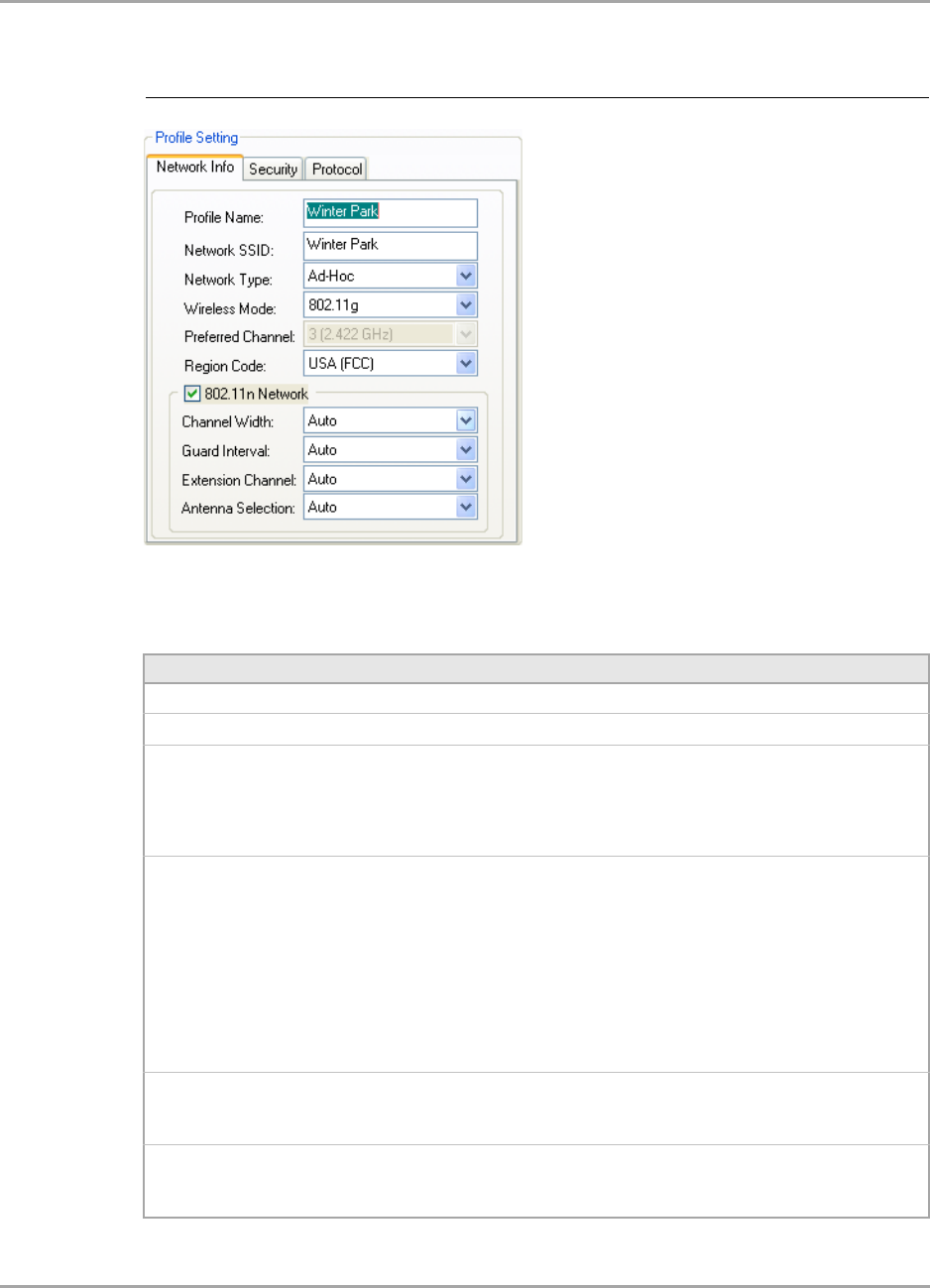
The Network Info tab fields are as follows.
Figure 14: Network Info Tab (Ad-Hoc Network)
Table 4: Network Info Tab Description
Field Description
Profile Name Name of profile selected
Network SSID Network SSID label
Network Type •Infrastructure
Connects to an existing Infrastructure network
•Ad-Hoc
Either connects to an existing Ad-Hoc network or initiates a new
Ad-Hoc network
Wireless Mode •Auto
Connects to either an 802.11g network or to an 802.11b network
•802.11g
Connects either to an 802.11g network or to an 802.11b network
•802.11b
Connects to an 802.11b network only
•802.11n (2.4 GHz)
Connects to an 802.11n network with 2.4 GHz
•802.11n (5 GHz)
Connects to an 802.11n network with 5 GHz
Preferred Channel Channel being used for an Ad-Hoc network initiated by the client card
The channel can be selected only at creation of a new profile (Ad-Hoc
network only).
Region Code Sets the region code
Available options are Default, USA (FCC), Canada (IC), Europe (ETSI),
Spain, France, Japan (MKK), Taiwan (DGT), and Australia/Korea
Note to US model owner: To comply with US FCC regulation, the country selection function has
been completely removed from all US models. The above function is for non-US models only.
CB-82/MB-82/EC-82/MC-82
User Guide
Doc. No. MV-S800473-00 Rev. B CONFIDENTIAL Copyright © 2007 Marvell
Page 24 Document Classification: Proprietary Information August 14, 2007, 2.00
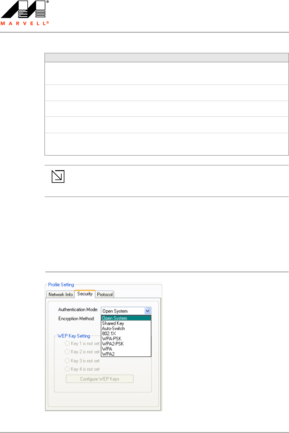
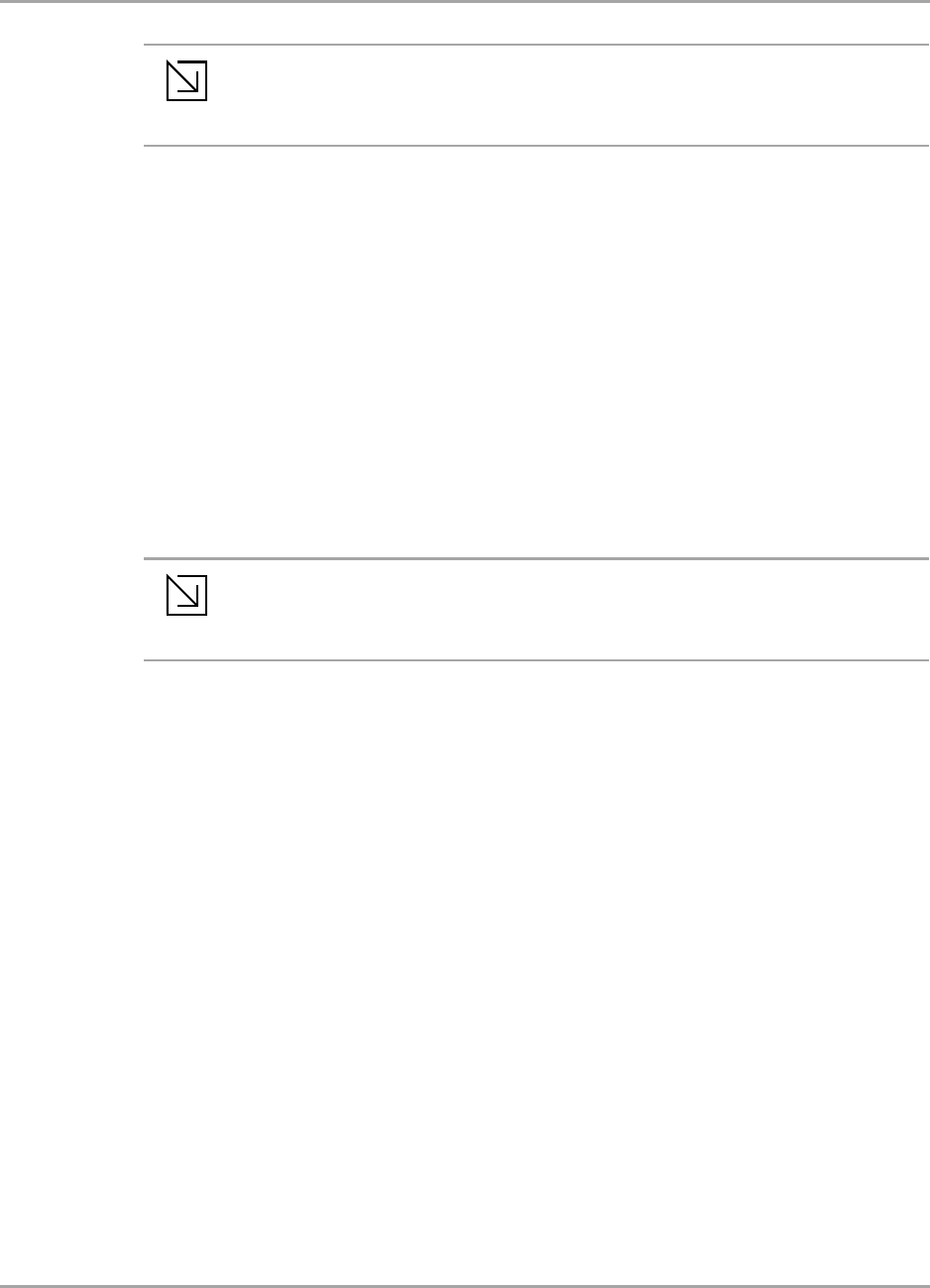
3.2.2 Profile Setting—Security Tab
Clicking the Security tab displays the following security options:
Authentication Mode
Encryption Method (Security off, WEP, TKIP, and AES)
Key settings (for legacy authentication modes) or 802.1X Authentication Protocol selection (for
802.1X authentication modes)
802.11n Network Enables/disables draft-802.11n functionality
If enabled, the Modulation and Coding Scheme (MCS) index and 802.11n
options can be configured.
Channel Width Sets the channel bandwidth
Available options are Auto, 20 MHz, and 40 MHz. The default is Auto.
Guard Interval Sets the Guard Interval
Available options are Auto, Standard, and Short. The default is Auto.
Extension Channel Sets the extension channel mode when bandwidth is 40 MHz
Available options are Auto, None, Lower, and Upper. The default is Auto.
Antenna Selection Sets the antenna selections
Available options are Auto, Antenna A, Antenna B, 2 by 2, and 2 by 3.
The default is Auto.
Note
The fields Wireless Mode and Preferred Channel are used only when a new Ad-Hoc
network is initiated by the client card. These two attributes are ignored when the client
card is connected to an existing Ad-Hoc network with the same desired SSID.
Table 4: Network Info Tab Description (Continued)
Field Description
Figure 15: Security Tab—Authentication Modes
Marvell Wireless Configuration Utility User Interface
Profile Manager Tab
Copyright © 2007 Marvell CONFIDENTIAL Doc. No. MV-S800473-00 Rev. B
August 14, 2007, 2.00 Document Classification: Proprietary Information Page 25
3.2.3 Legacy Authentication Modes
The Marvell Wireless Configuration Utility currently supports the following legacy authentication
modes:
Open System—Open Authentication (no key or a pre-shared WEP key is required)
Shared Key—Shared Authentication (a pre-shared WEP key is required)
Auto Switch—Auto Select Authentication modes (no key or a pre-shared WEP key is required)
WPA-PSK—WPA Pre-Shared Key
WPA2-PSK—WPA2 Pre-Shared Key
If Open System or Auto Switch is selected as Authentication Mode, Security off and WEP are
available as Encryption Method. If Shared Key is selected as Authentication Mode, WEP is
pre-selected as Encryption Method. For details on how to configure the WEP key(s), see
Section 3.2.3.1.
If WPA-PSK or WPA2-PSK is selected as Authentication Mode, AES and TKIP are available as
Encryption Method. For details on how to define the pre-shared key, see Section 3.2.3.2.
Note
The authentication modes available depend on the network type selected on the
Network Info tab.
For Ad-Hoc networks, only Open System and Shared Key are available.
Note
The authentication modes available depend on the network type selected on the
Network Info tab.
For Ad-Hoc networks, only authentication modes without encryption or with WEP key
are available.
CB-82/MB-82/EC-82/MC-82
User Guide
Doc. No. MV-S800473-00 Rev. B CONFIDENTIAL Copyright © 2007 Marvell
Page 26 Document Classification: Proprietary Information August 14, 2007, 2.00
3.2.3.1 Open System / Shared Key / Auto Switch
The WEP key configuration for the authentication modes Open System, Shared Key, and Auto
Switch is identical:
1. Click Configure WEP Keys.
The Configure WEP Key window is displayed. For a detailed description of this window, see
Table 5 on page 27.
Figure 16: Security Tab—Open System with WEP
Figure 17: WEP Key Configuration Window
Marvell Wireless Configuration Utility User Interface
Profile Manager Tab
Copyright © 2007 Marvell CONFIDENTIAL Doc. No. MV-S800473-00 Rev. B
August 14, 2007, 2.00 Document Classification: Proprietary Information Page 27
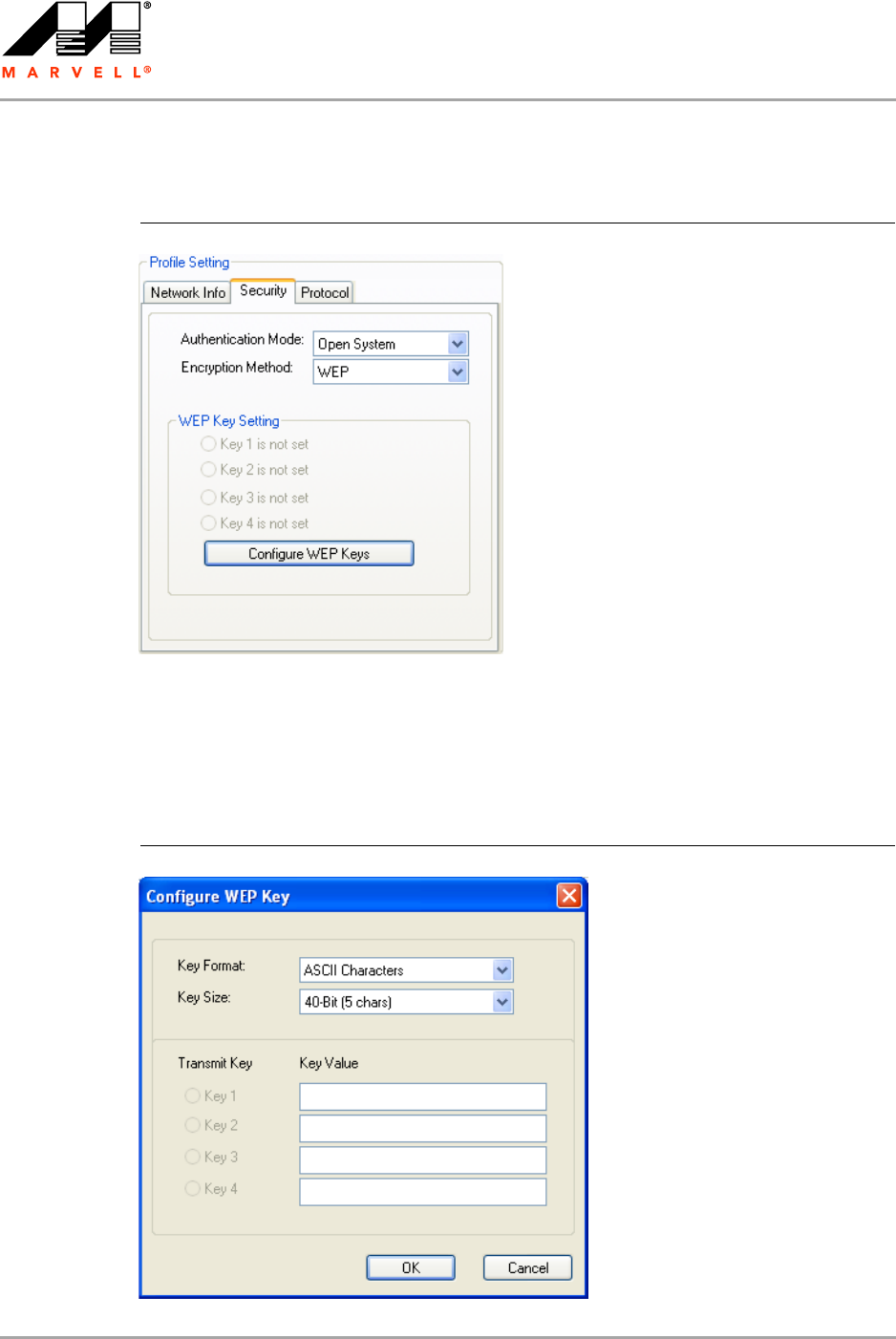
2. Select the required Key Format and Key Size.
3. Enter the Transmit Key(s).
4. Click OK to return to the Security tab of the Profile Settings.
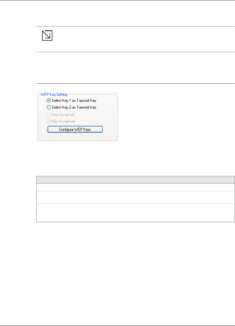
5. Select the WEP key to be used for the transmission.
6. Click Save to set the configuration.
Note
Up to four WEP keys are supported. The WEP key used for the transmission must be
identical on the sending and receiving station.
Figure 18: WEP Key Setting
Table 5: WEP Key Configuration Window Description
Field Description
Key Format Either ASCII characters or hexadecimal digits
Key Size • 40-bit, 5 character ASCII key size (40-bit, 10 hexadecimal digits)
• 104-bit, 13 character ASCII key size (104-bit, 26 hexadecimal digits)
Transmit Key/Key Value Key to be used as transmit key. The key value is in ASCII or hexadecimal,
depending on the format selected. The key value size shown depends on
the key size selected.
CB-82/MB-82/EC-82/MC-82
User Guide
Doc. No. MV-S800473-00 Rev. B CONFIDENTIAL Copyright © 2007 Marvell
Page 28 Document Classification: Proprietary Information August 14, 2007, 2.00
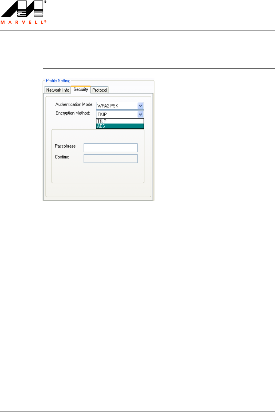
3.2.3.2 WPA-PSK / WPA2-PSK
The definition of the pre-shared key is identical for both WPA-PSK/WPA2-PSK with TKIP/AES:
1. Enter the pre-shared key into the Passphrase and Confirm boxes.
The passphrase must contain between 8 and 63 ASCII characters.
2. Click Save to set the configuration.
Figure 19: Security Tab—WPA2-PSK with TKIP
Marvell Wireless Configuration Utility User Interface
Profile Manager Tab
Copyright © 2007 Marvell CONFIDENTIAL Doc. No. MV-S800473-00 Rev. B
August 14, 2007, 2.00 Document Classification: Proprietary Information Page 29
3.2.4 802.1X Authentication Modes
The Marvell Wireless Configuration Utility currently supports the following 802.1X authentication
modes:
802.1X—Open System with 802.1X Authentication (EAP/TLS, PEAP, EAP/TTLS, LEAP or
EAP-FAST)
WPA—WPA with 802.1X Authentication (EAP/TLS, PEAP, EAP/TTLS, LEAP or EAP-FAST)
WPA2—WPA2 with 802.1X Authentication (EAP/TLS, PEAP, EAP/TTLS, LEAP or EAP-FAST)
For all 802.1X authentication modes, CCX support can be enabled.
If 802.1X (Open System) is selected as Authentication Mode, WEP is pre-selected as Encryption
Method. If WPA or WPA2 is selected, TKIP and AES are available as Encryption Method. For details
on how to define the different 802.1X authentication protocols (EAP/TLS, PEAP, EAP/TTLS, LEAP,
and EAP-FAST), see the following subsections.
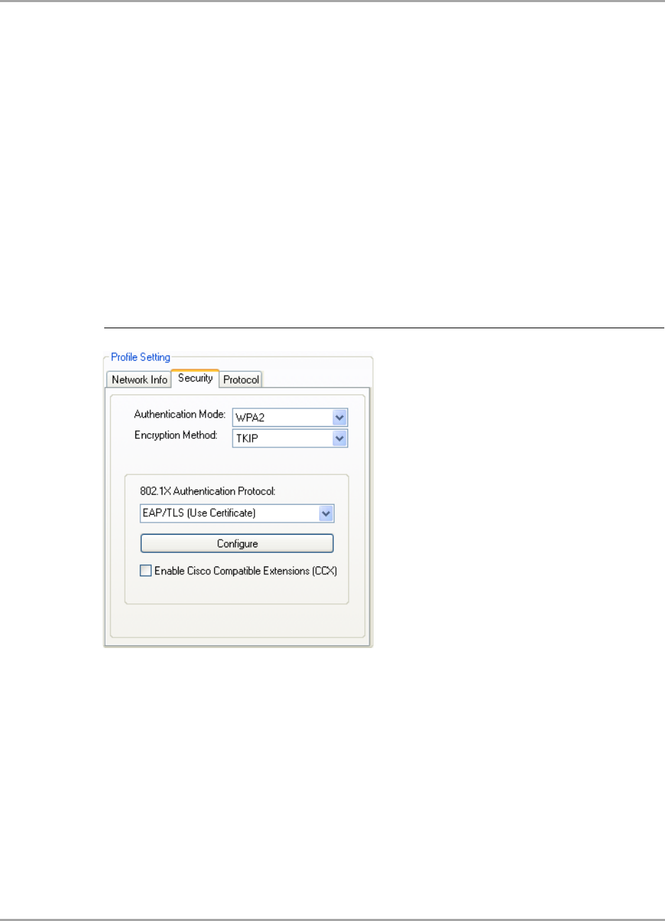
3.2.4.1 802.1X / WPA / WPA2 with EAP/TLS
The definition of the EAP/TLS authentication protocol for the authentication modes 802.1X, WPA,
and WPA2 is identical:
1. Select EAP/TLS (Use Certificate) as 802.1X Authentication Protocol.
2. Click Configure.
The EAP/TLS (Use Certificate) window is displayed. For a detailed description of this window,
see Table 6 on page 34.
Figure 20: Security Tab—WPA2 with EAP/TLS (Use Certificate)
CB-82/MB-82/EC-82/MC-82
User Guide
Doc. No. MV-S800473-00 Rev. B CONFIDENTIAL Copyright © 2007 Marvell
Page 30 Document Classification: Proprietary Information August 14, 2007, 2.00
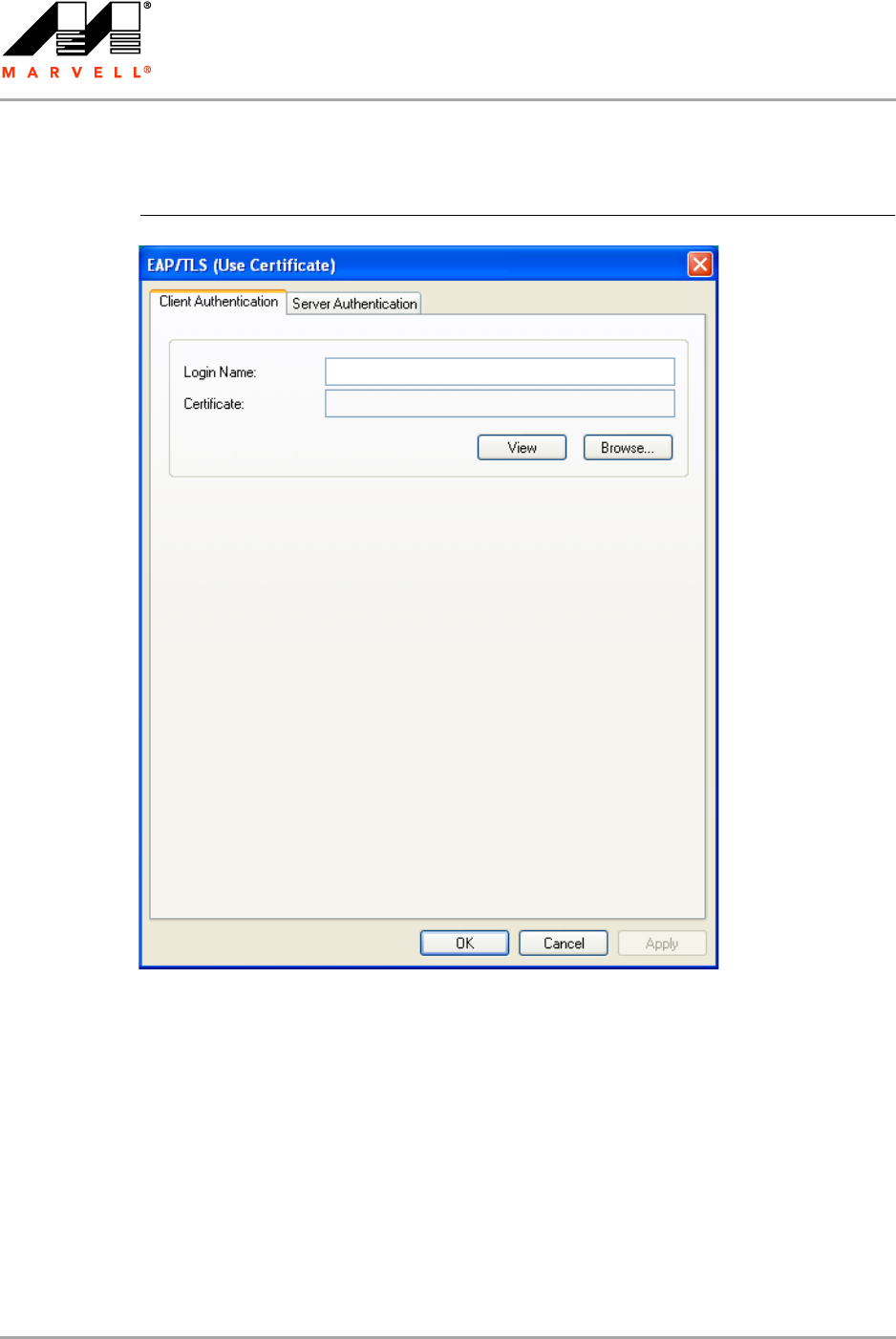
3. On the Client Authentication tab, enter your Login Name.
4. Click Browse.
The Select Certificate window is displayed. For a detailed description of this window, see
Table 7 on page 34.
Figure 21: EAP/TLS (Use Certificate) Configuration Window—Client Authentication
Tab
Marvell Wireless Configuration Utility User Interface
Profile Manager Tab
Copyright © 2007 Marvell CONFIDENTIAL Doc. No. MV-S800473-00 Rev. B
August 14, 2007, 2.00 Document Classification: Proprietary Information Page 31
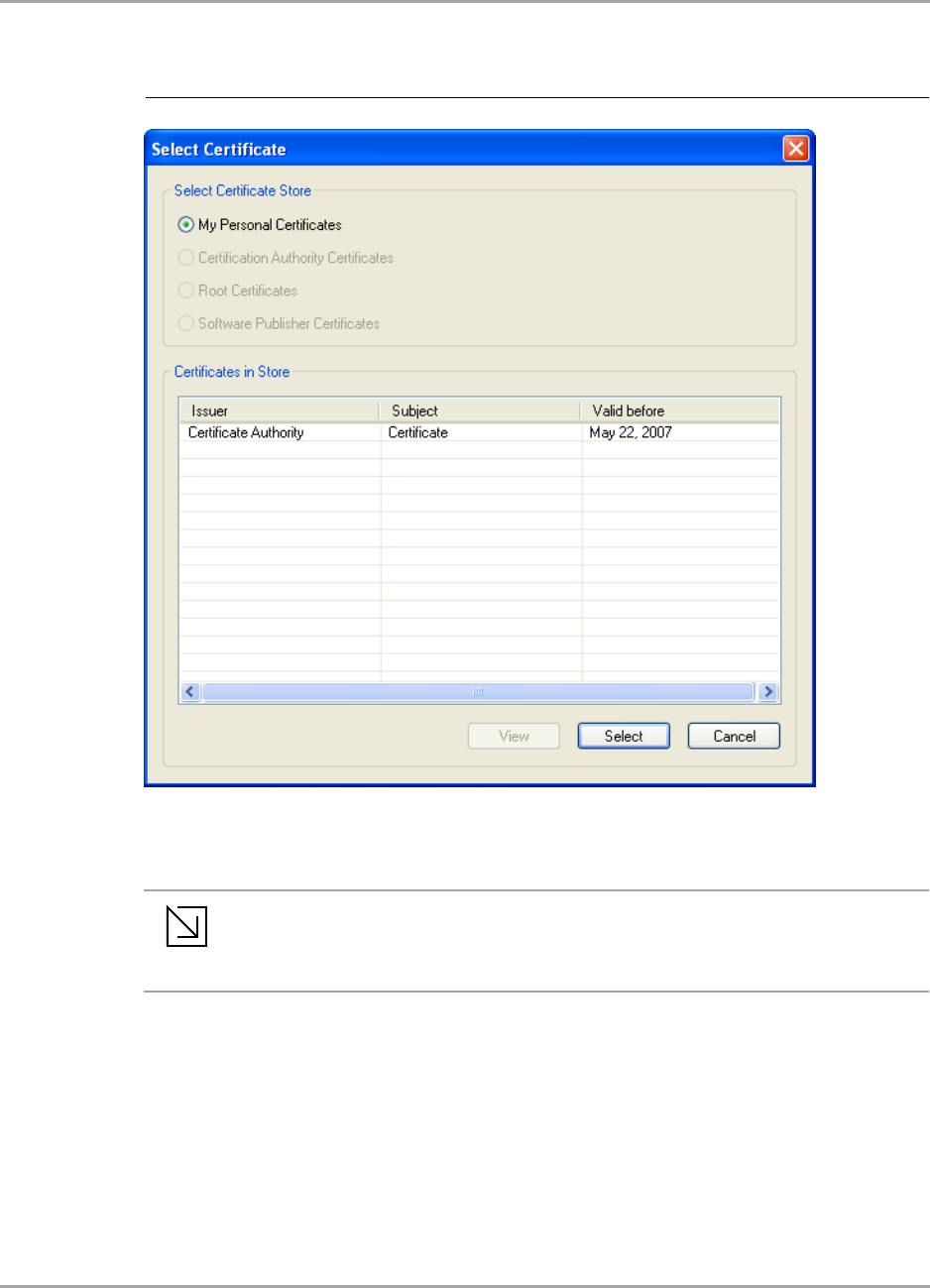
5. In the Certificates in Store list, click the personal certificate to be used for the client
authentication.
6. Click Select to confirm your selection and to return to the EAP/TLS (Use Certificate) window.
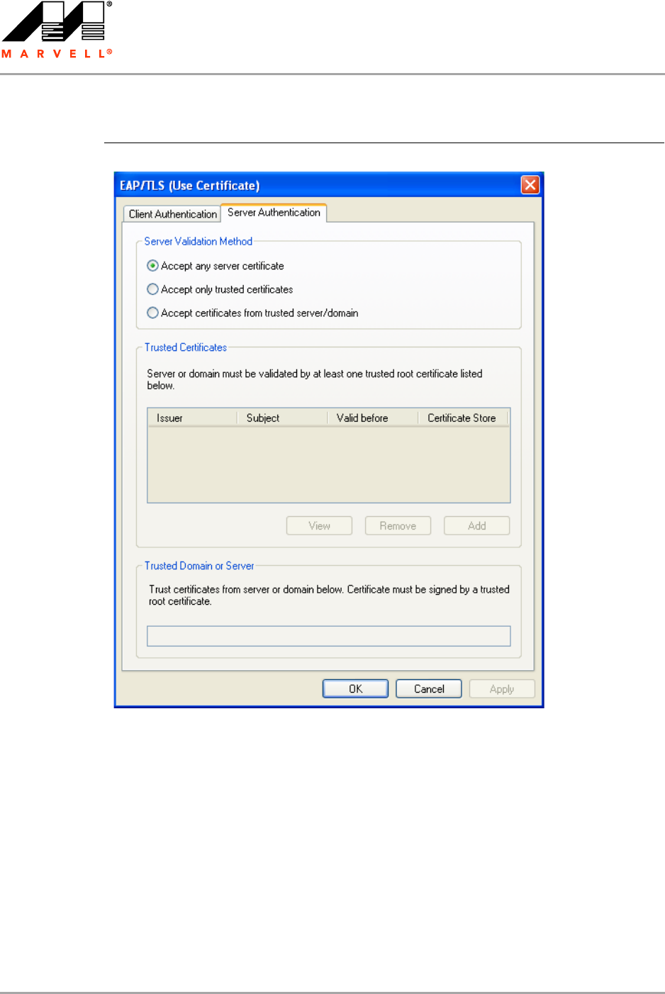
7. If you want to specify particular server certificates to be accepted (instead of accepting any
certificate sent by the server), click the Server Authentication tab. For a detailed description of
this window, see Table 8 on page 35.
Otherwise, continue with step 14.
Figure 22: Select Certificate Window (Client Certificates)
Note
If the required certificate is not yet installed on your system or if you do not know which
certificate to use, contact your network administrator.
CB-82/MB-82/EC-82/MC-82
User Guide
Doc. No. MV-S800473-00 Rev. B CONFIDENTIAL Copyright © 2007 Marvell
Page 32 Document Classification: Proprietary Information August 14, 2007, 2.00
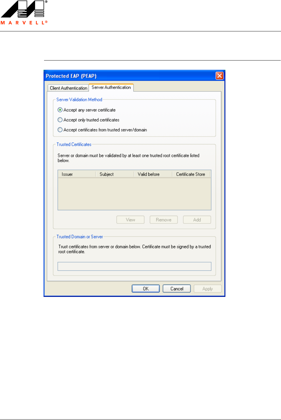
8. Select the required Server Validation Method.
9. For Accept only trusted certificates or Accept certificates from trusted server/domain,
click Add to select the appropriate certificate.
The Select Certificate window is displayed. For a detailed description of this window, see
Table 9 on page 35.
Figure 23: EAP/TLS Configuration Window—Server Authentication Tab

Marvell Wireless Configuration Utility User Interface
Profile Manager Tab
Copyright © 2007 Marvell CONFIDENTIAL Doc. No. MV-S800473-00 Rev. B
August 14, 2007, 2.00 Document Classification: Proprietary Information Page 33
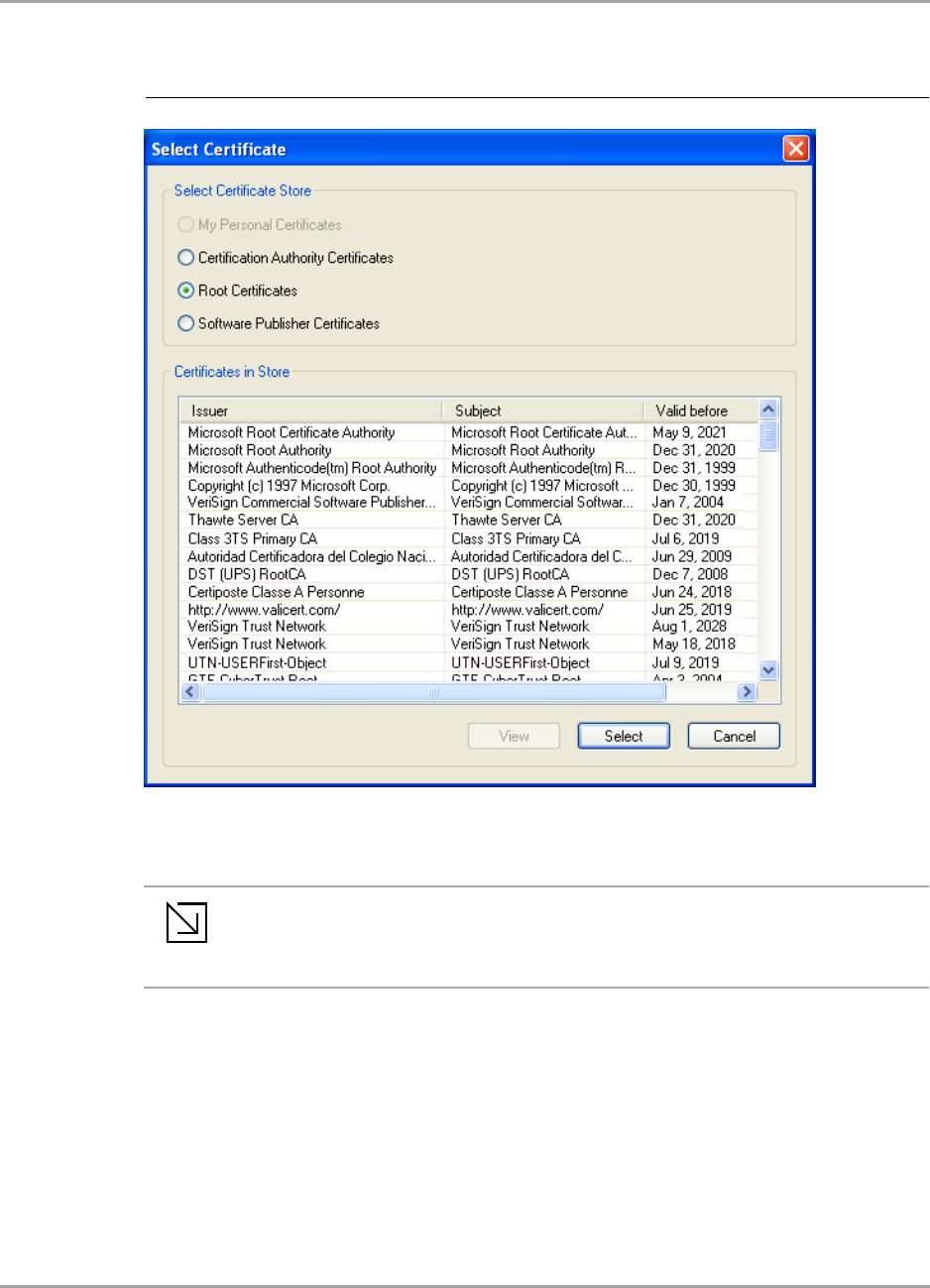
10. On the Select Certificate window, select the Certificate Store.
11. From the Certificates in Store list, click the certificate to be used for the server authentication.
12. Click Select to confirm your selection and to return to the EAP/TLS (Use Certificate) window.
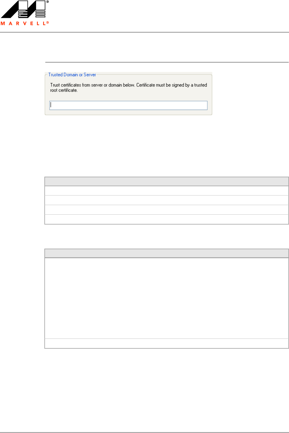
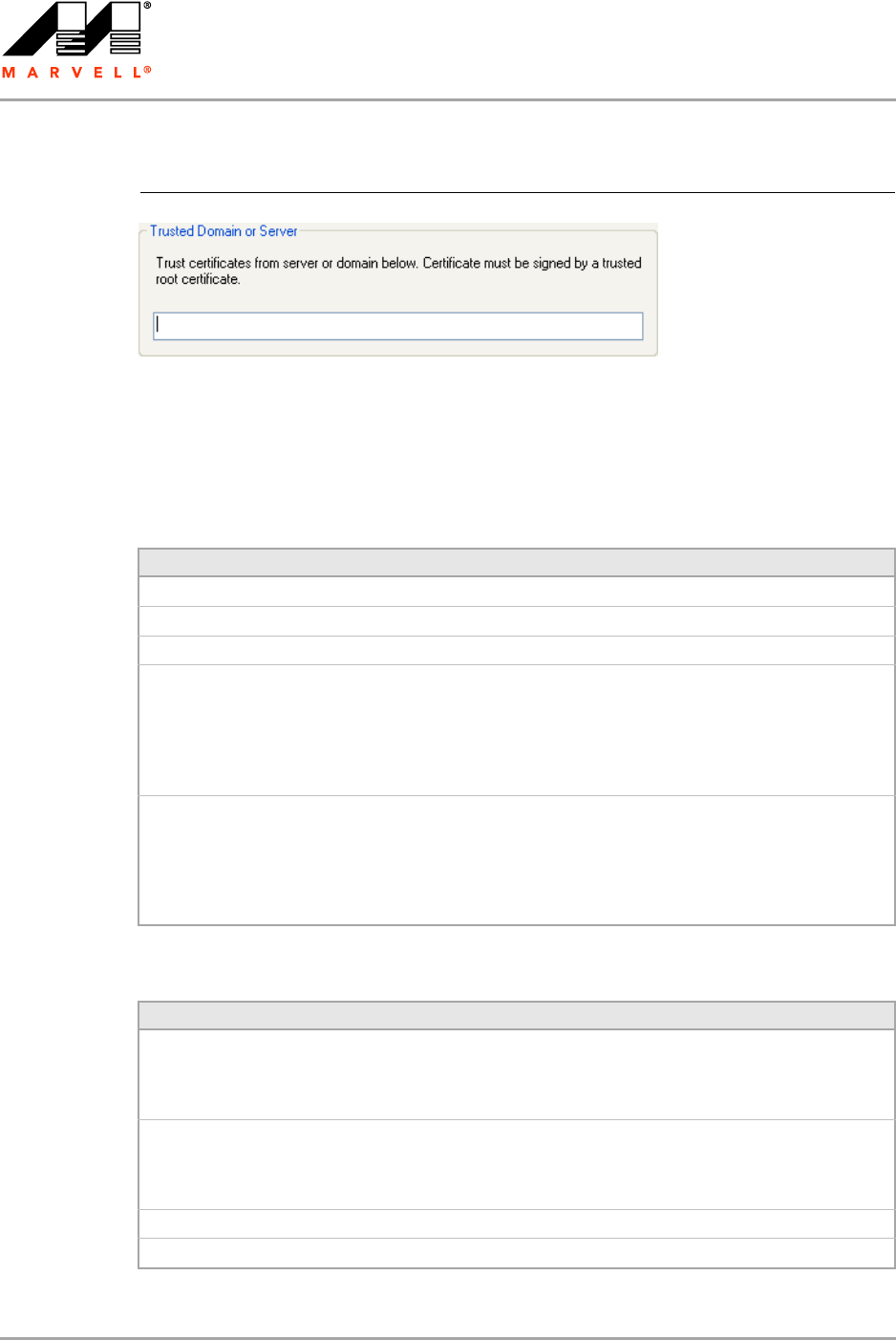
13. If you have selected Accept certificates from trusted server/domain, enter the appropriate
server name or domain name into the Trusted Domain or Server box.
Figure 24: Select Certificate Window (Server Certificates)
Note
If the required certificate is not yet installed on your system or if you do not know which
certificate to use, contact your network administrator.
CB-82/MB-82/EC-82/MC-82
User Guide
Doc. No. MV-S800473-00 Rev. B CONFIDENTIAL Copyright © 2007 Marvell
Page 34 Document Classification: Proprietary Information August 14, 2007, 2.00
14. Click OK to return to the Security tab of the Profile Settings.
15. If CCX compatibility is required, select the Enable Cisco Compatible Extensions (CCX) check
box.
16. Click Save to set the configuration.
Figure 25: Server Authentication—Trusted Domain or Server
Table 6: EAP/TLS Configuration Window Description—Client Authentication Tab
Field/Button Description
Login Name Login name to the authentication server
Certificate Certificate to be used for client authentication
View Shows the selected certificate
Browse Selects the certificate from the certificates store
Table 7: Select Certificate Window Description (Client Certificates)
Area Description
Select Certificate Store Certificate stores with certificates to be used for client authentication:
•My Personal Certificates
Contains personal certificates
•Certification Authority Certificates
Contains certificates issued by a Certification Authority (CA) (for
server authentication only)
•Root Certificates
Contains certificates issued by a CA who uses an own Trusted Root
CA certificate (for server authentication only)
•Software Publisher Certificates
Contains certificates issued by a software publisher (for server
authentication only)
Certificates in Store Lists the personal certificates installed on the client system
Marvell Wireless Configuration Utility User Interface
Profile Manager Tab
Copyright © 2007 Marvell CONFIDENTIAL Doc. No. MV-S800473-00 Rev. B
August 14, 2007, 2.00 Document Classification: Proprietary Information Page 35
Table 8: EAP/TLS Configuration Window Description—Server Authentication Tab
Area/Button Description
Server Validation Method Certificates to be accepted for server authentication:
•Accept any server certificate
•Accept only trusted certificates
•Accept certificates from trusted server/domain
Trusted Certificates Lists the trusted certificates installed on the client system
Required, when Accept only trusted certificates or Accept certificates
from trusted server/domain is selected. The appropriate root certificate
of the server/domain must also be installed on the client system.
View Shows the selected certificate
Remove Deletes the selected certificate from the Trusted Certificates list
Add Selects the certificate from the certificates store
Trusted Domain or Server Domain or server the certificate to be trusted is received from
Required, when Accept certificates from trusted server/domain is
selected
Table 9: Select Certificate Window Description (Server Certificates)
Area Description
Select Certificate Store Certificate stores with certificates to be used for server authentication:
•My Personal Certificates
Contains personal certificates (for client authentication only)
•Certification Authority Certificates
Contains certificates issued by a CA
•Root Certificates
Contains certificates issued by a CA who uses an own Trusted Root
CA certificate
•Software Publisher Certificates
Contains certificates issued by a software publisher
Certificates in Store Lists the certificates installed in the selected certificate store on the client
system
CB-82/MB-82/EC-82/MC-82
User Guide
Doc. No. MV-S800473-00 Rev. B CONFIDENTIAL Copyright © 2007 Marvell
Page 36 Document Classification: Proprietary Information August 14, 2007, 2.00
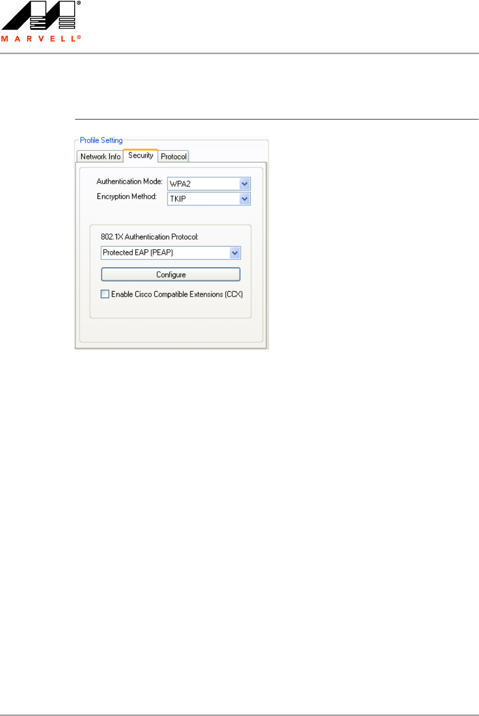
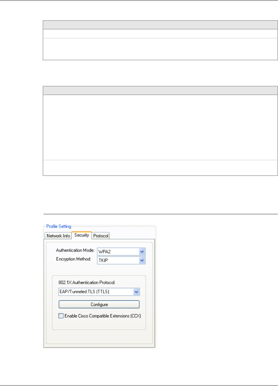
3.2.4.2 802.1X / WPA / WPA2 with PEAP
The definition of the PEAP authentication protocol for the authentication modes 802.1X, WPA, and
WPA2 is identical:
1. Select Protected EAP (PEAP) as 802.1X Authentication Protocol.
2. Click Configure.
The Protected EAP (PEAP) window is displayed. For a detailed description of this window, see
Table 10 on page 40.
Figure 26: Security Tab—WPA2 with PEAP
Marvell Wireless Configuration Utility User Interface
Profile Manager Tab
Copyright © 2007 Marvell CONFIDENTIAL Doc. No. MV-S800473-00 Rev. B
August 14, 2007, 2.00 Document Classification: Proprietary Information Page 37
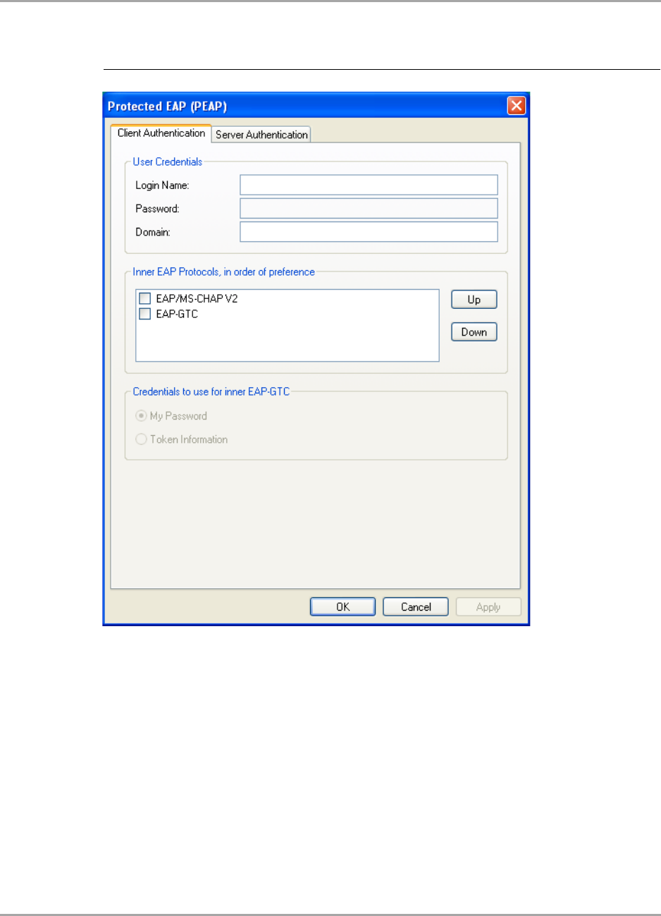
3. On the Client Authentication tab, enter your Login Name, Password, and Domain.
The domain information is optional.
4. From the Inner EAP Protocols list, select the EAP protocol to be used.
If required, change the order of preference.
5. If you have selected EAP-GTC, select the credentials to be used for login.
6. If you want to specify particular server certificates to be accepted (instead of accepting any
certificate sent by the server), click the Server Authentication tab. For a detailed description of
this window, see Table 11 on page 40.
Otherwise, continue with step 13.
Figure 27: PEAP Configuration Window—Client Authentication Tab
CB-82/MB-82/EC-82/MC-82
User Guide
Doc. No. MV-S800473-00 Rev. B CONFIDENTIAL Copyright © 2007 Marvell
Page 38 Document Classification: Proprietary Information August 14, 2007, 2.00
7. Select the required Server Validation Method.
8. For Accept only trusted certificates or Accept certificates from trusted server/domain,
click Add to select the appropriate certificate.
The Select Certificate window is displayed. For a detailed description of this window, see
Table 12 on page 41.
Figure 28: PEAP Configuration Window—Server Authentication Tab
Marvell Wireless Configuration Utility User Interface
Profile Manager Tab
Copyright © 2007 Marvell CONFIDENTIAL Doc. No. MV-S800473-00 Rev. B
August 14, 2007, 2.00 Document Classification: Proprietary Information Page 39
9. On the Select Certificate window, select the Certificate Store.
10. From the Certificates in Store list, click the certificate to be used for the server authentication.
11. Click Select to confirm your selection and to return to the Protected EAP (PEAP) window.
12. If you have selected Accept certificates from trusted server/domain, enter the server name
or the domain name into the Trusted Domain or Server box.
Figure 29: Select Certificate Window (Server Certificates)
Note
If the required certificate is not yet installed on your system or if you do not know which
certificate to use, contact your network administrator.
CB-82/MB-82/EC-82/MC-82
User Guide
Doc. No. MV-S800473-00 Rev. B CONFIDENTIAL Copyright © 2007 Marvell
Page 40 Document Classification: Proprietary Information August 14, 2007, 2.00
13. Click OK to return to the Security tab of the Profile Settings.
14. If CCX compatibility is required, select the Enable Cisco Compatible Extensions (CCX) check
box.
15. Click Save to set the configuration.
Figure 30: Server Authentication—Trusted Domain or Server
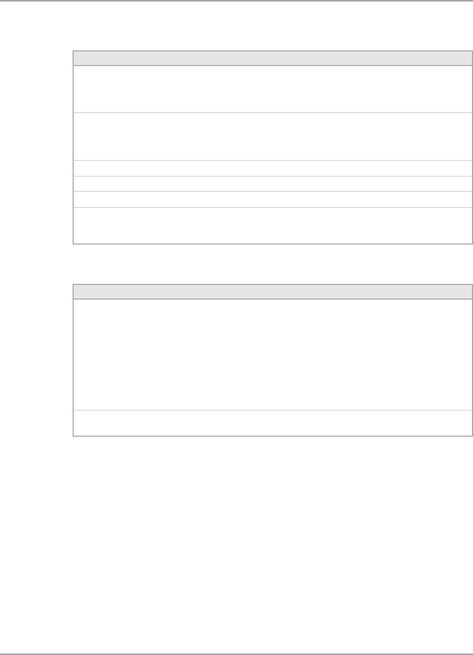
Table 10: PEAP Configuration Window Description—Client Authentication Tab
Area/Field Description
Login Name Login name to the authentication server
Password Password for login to the authentication server
Domain Domain name for login to the authentication server (optional)
Inner EAP Protocols EAP protocol to be used for inner (client) authentication:
•EAP/MS-CHAP V2
Uses Microsoft Challenge Handshake Authentication Protocol
(CHAP) v2 for authentication
•EAP-GTC
Uses Generic Token Card (GTC) for authentication
Credentials to use for
inner EAP-GTC
Credentials to be used for inner (client) authentication:
•My Password
Uses a user-specific password
•Token information
Uses a token that generates a one-time password
Required, when EAP-GTC is selected as Inner EAP Protocol
Table 11: PEAP Configuration Window Description—Server Authentication Tab
Area/Button Description
Server Validation Method Certificates to be accepted for server authentication:
•Accept any server certificate
•Accept only trusted certificates
•Accept certificates from trusted server/domain
Trusted Certificates Lists the trusted certificates installed on the client system
Required, when Accept only trusted certificates or Accept certificates
from trusted server/domain is selected. The appropriate root certificate
of the server/domain must also be installed on the client system.
View Shows the selected certificate
Remove Deletes the selected certificate from the Trusted Certificates list
Marvell Wireless Configuration Utility User Interface
Profile Manager Tab
Copyright © 2007 Marvell CONFIDENTIAL Doc. No. MV-S800473-00 Rev. B
August 14, 2007, 2.00 Document Classification: Proprietary Information Page 41
3.2.4.3 802.1X / WPA / WPA2 with EAP/TTLS
Add Selects the certificate from the certificates store
Trusted Domain or Server Domain or server the certificate to be trusted is received from
Required, when Accept certificates from trusted server/domain is
selected
Table 12: Select Certificate Window Description (Server Certificates)
Area Description
Select Certificate Store Certificate stores with certificates to be used for server authentication:
•My Personal Certificates
Contains personal certificates (for client authentication only)
•Certification Authority Certificates
Contains certificates issued by a CA
•Root Certificates
Contains certificates issued by a CA who uses an own Trusted Root
CA certificate
•Software Publisher Certificates
Contains certificates issued by a software publisher
Certificates in Store Lists the certificates installed in the selected certificate store on the client
system
Table 11: PEAP Configuration Window Description—Server Authentication Tab
Area/Button Description
Figure 31: Security Tab—WPA2 with EAP/TTLS
CB-82/MB-82/EC-82/MC-82
User Guide
Doc. No. MV-S800473-00 Rev. B CONFIDENTIAL Copyright © 2007 Marvell
Page 42 Document Classification: Proprietary Information August 14, 2007, 2.00
The definition of the EAP/TTLS authentication protocol for the authentication modes 802.1X, WPA,
and WPA2 is identical:
1. Select EAP/Tunneled TLS (TTLS) as 802.1X Authentication Protocol.
2. Click Configure.
The EAP/Tunneled TLS (TTLS) window is displayed. For a detailed description of this window,
see Table 13 on page 45.
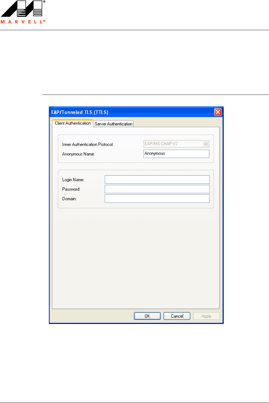
3. On the Client Authentication tab, enter your Anonymous Name, Login Name, Password,
and Domain.
The domain information is optional.
4. If you want to specify particular server certificates to be accepted (instead of accepting any
certificate sent by the server), click the Server Authentication tab. For a detailed description of
this window, see Table 14 on page 45.
Otherwise, continue with step 11.
Figure 32: EAP/TTLS Configuration Window—Client Authentication Tab
Marvell Wireless Configuration Utility User Interface
Profile Manager Tab
Copyright © 2007 Marvell CONFIDENTIAL Doc. No. MV-S800473-00 Rev. B
August 14, 2007, 2.00 Document Classification: Proprietary Information Page 43
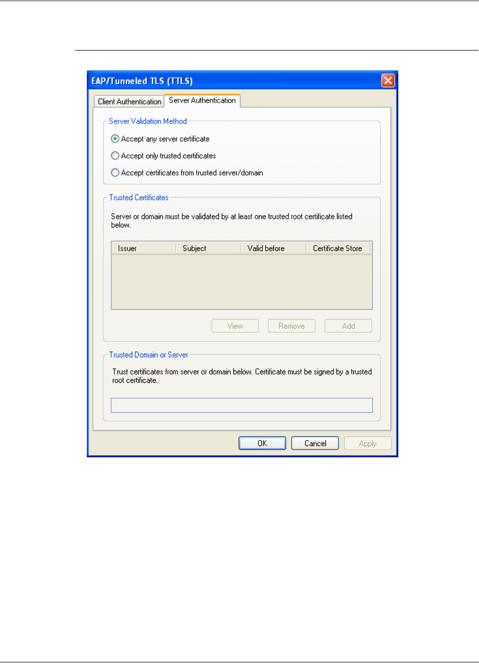
5. Select the required Server Validation Method.
6. For Accept only trusted certificates or Accept certificates from trusted server/domain,
click Add to select the appropriate certificate.
The Select Certificate window is displayed. For a detailed description of this window, see
Table 15 on page 46.
Figure 33: EAP/TTLS Configuration Window—Server Authentication Tab
CB-82/MB-82/EC-82/MC-82
User Guide
Doc. No. MV-S800473-00 Rev. B CONFIDENTIAL Copyright © 2007 Marvell
Page 44 Document Classification: Proprietary Information August 14, 2007, 2.00
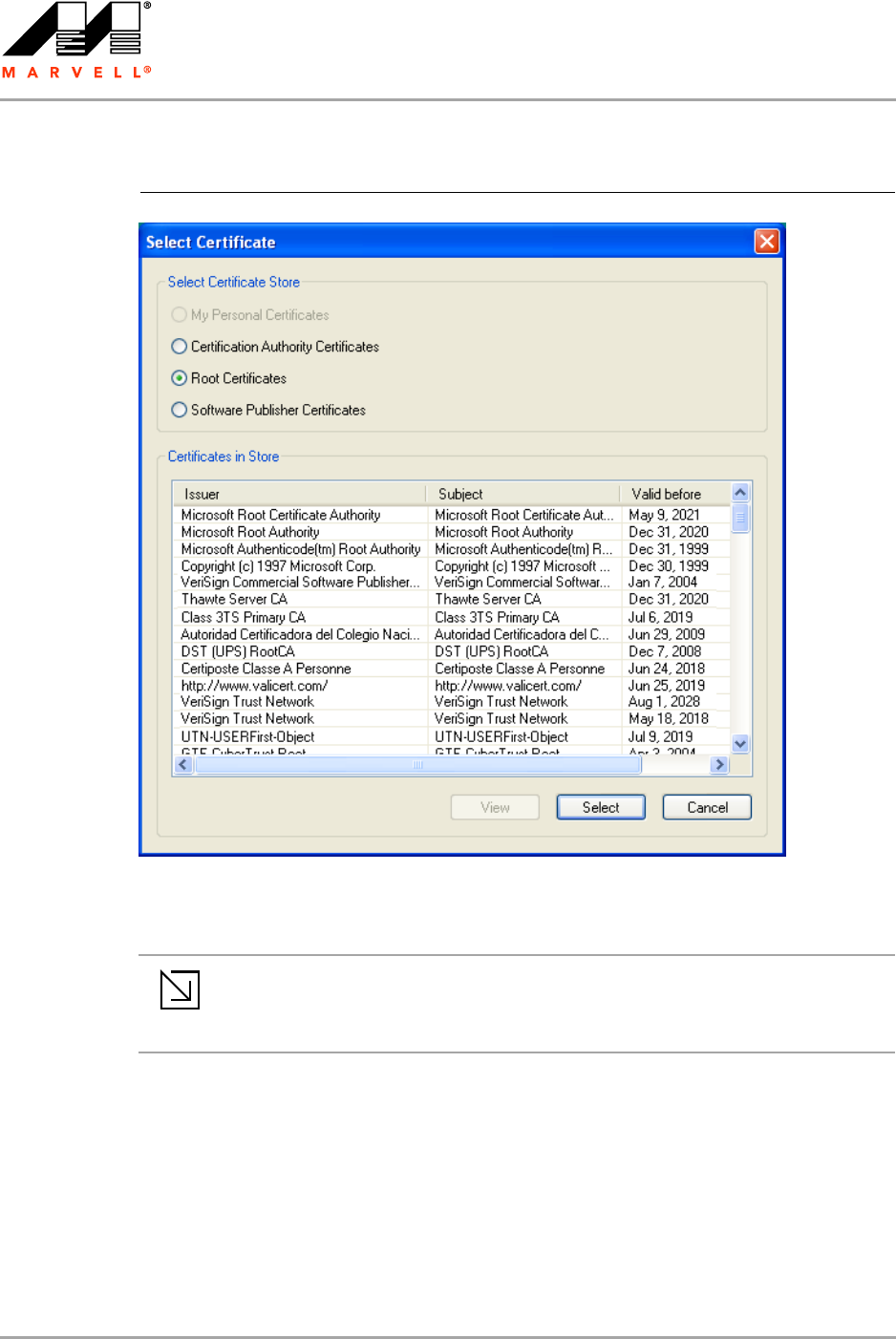
7. On the Select Certificate window, select the Certificate Store.
8. From the Certificates in Store list, click the certificate to be used for the server authentication.
9. Click Select to confirm your selection and to return to the EAP/Tunneled TLS (TTLS) window.
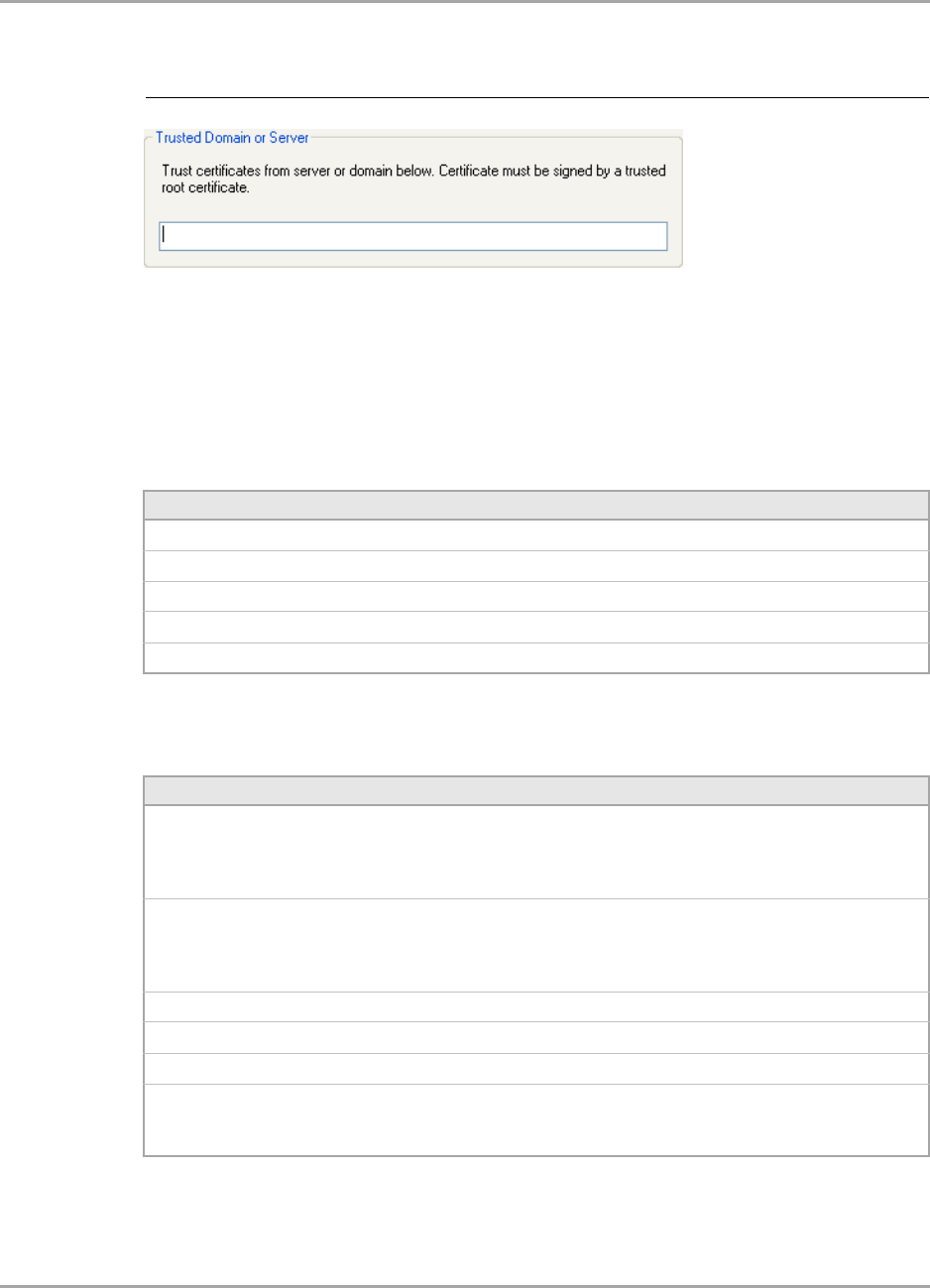
10. If you have selected Accept certificates from trusted server/domain, enter the server name
or the domain name into the Trusted Domain or Server box.
Figure 34: Select Certificate Window (Server Certificates)
Note
If the required certificate is not yet installed on your system or if you do not know which
certificate to use, contact your network administrator.
Marvell Wireless Configuration Utility User Interface
Profile Manager Tab
Copyright © 2007 Marvell CONFIDENTIAL Doc. No. MV-S800473-00 Rev. B
August 14, 2007, 2.00 Document Classification: Proprietary Information Page 45
11. Click OK to return to the Security tab of the Profile Settings.
12. If CCX compatibility is required, select the Enable Cisco Compatible Extensions (CCX) check
box.
13. Click Save to set the configuration.
Figure 35: Server Authentication—Trusted Domain or Server
Table 13: EAP/TTLS Configuration Window Description—Client Authentication
Tab
Field Description
Inner Authentication Protocol Protocol to be used for inner (client) authentication
Anonymous Name Anonymous login name to the authentication server
Login Name Login name to the authentication server
Password Password for login to the authentication server
Domain Domain name for login to the authentication server (optional)
Table 14: EAP/TTLS Configuration Window Description—Server Authentication
Tab
Area/Button Description
Server Validation Method Certificates to be accepted for server authentication:
•Accept any server certificate
•Accept only trusted certificates
•Accept certificates from trusted server/domain
Trusted Certificates Lists the trusted certificates installed on the client system
Required, when Accept only trusted certificates or Accept certificates
from trusted server/domain is selected. The appropriate root certificate
of the server/domain must also be installed on the client system.
View Shows the selected certificate
Remove Deletes the selected certificate from the Trusted Certificates list
Add Selects the certificate from the certificates store
Trusted Domain or Server Domain or server the certificate to be trusted is received from
Required, when Accept certificates from trusted server/domain is
selected
CB-82/MB-82/EC-82/MC-82
User Guide
Doc. No. MV-S800473-00 Rev. B CONFIDENTIAL Copyright © 2007 Marvell
Page 46 Document Classification: Proprietary Information August 14, 2007, 2.00
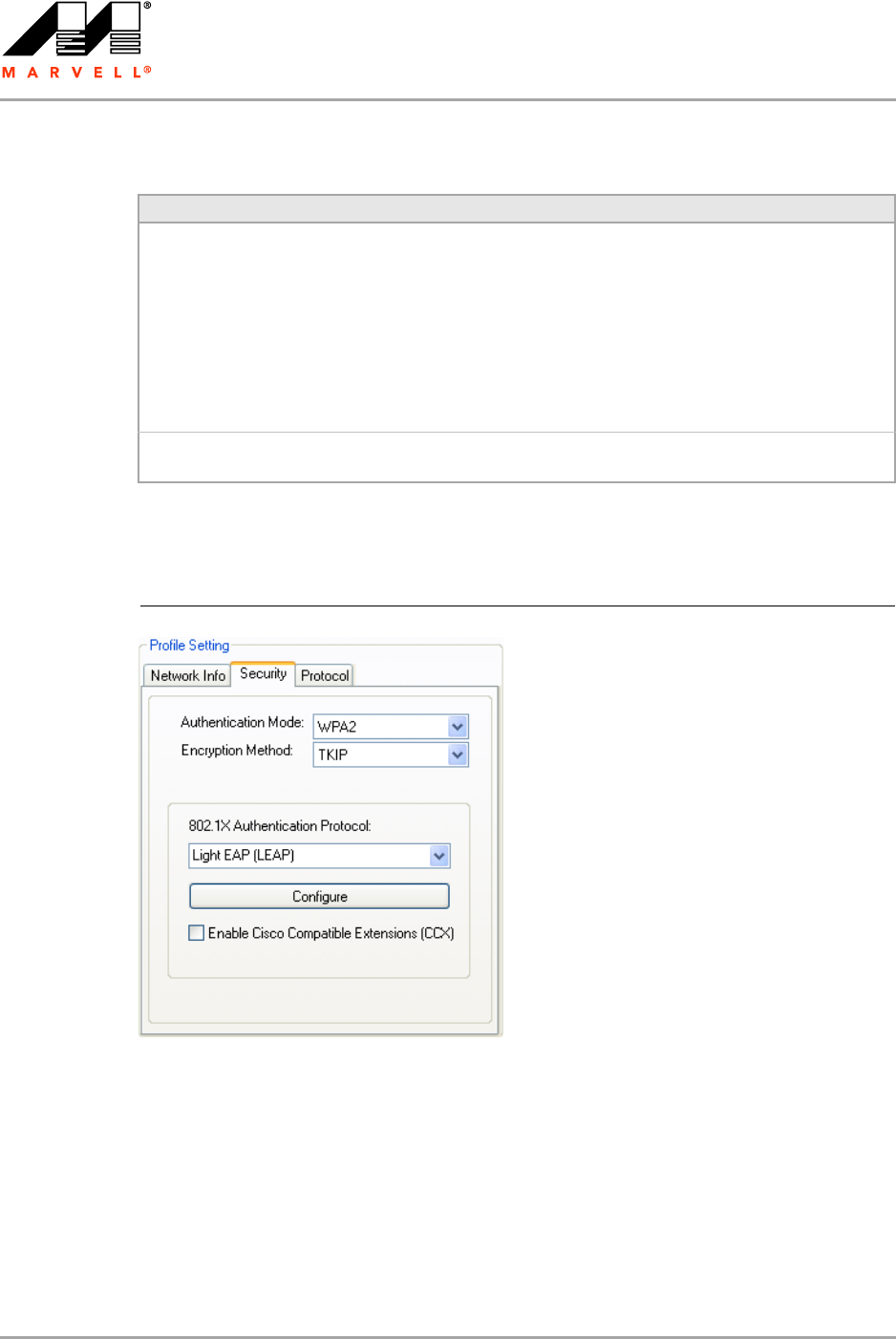
3.2.4.4 802.1X / WPA / WPA2 with LEAP
The definition of the LEAP authentication protocol for the authentication modes 802.1X, WPA, and
WPA2 is identical:
1. Select Light EAP (LEAP) as 802.1X Authentication Protocol.
2. Click Configure.
The LEAP Configuration window is displayed. For a detailed description of this window, see
Table 16 on page 48.
Table 15: Select Certificate Window Description (Server Certificates)
Area Description
Select Certificate Store Certificate stores with certificates to be used for server authentication:
•My Personal Certificates
Contains personal certificates (for client authentication only)
•Certification Authority Certificates
Contains certificates issued by a CA
•Root Certificates
Contains certificates issued by a CA who uses an own Trusted Root
CA certificate
•Software Publisher Certificates
Contains certificates issued by a software publisher
Certificates in Store Lists the certificates installed in the selected certificate store on the client
system
Figure 36: Security Tab—WPA2 with LEAP
Marvell Wireless Configuration Utility User Interface
Profile Manager Tab
Copyright © 2007 Marvell CONFIDENTIAL Doc. No. MV-S800473-00 Rev. B
August 14, 2007, 2.00 Document Classification: Proprietary Information Page 47
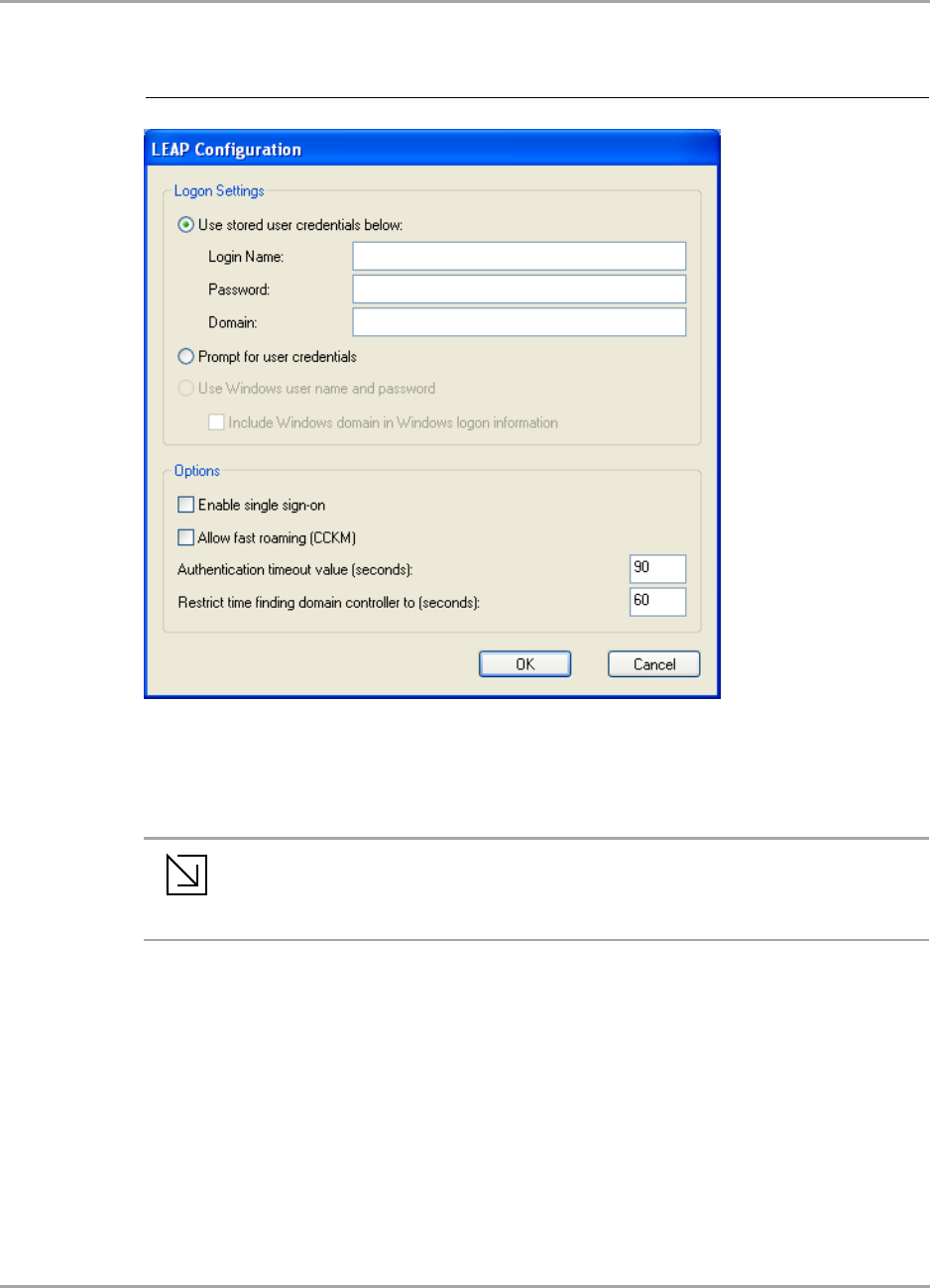
3. Under Logon Settings, select the user credentials (and, if required, Login Name, Password,
and Domain) to be used for the client authentication.
Use Windows user name and password is only available if Enable single sign-on is
selected.
4. If required, specify further settings under Options.
5. Click OK to return to the Security tab of the Profile Settings.
6. If CCX compatibility is required, select the Enable Cisco Compatible Extensions (CCX) check
box.
7. Click Save to set the configuration.
Figure 37: LEAP Configuration Window
Note
To enable single sign-on, administrator rights are required.
Using single sign-on authentication for the first time requires a restart of your
system after having saved the LEAP configuration.
CB-82/MB-82/EC-82/MC-82
User Guide
Doc. No. MV-S800473-00 Rev. B CONFIDENTIAL Copyright © 2007 Marvell
Page 48 Document Classification: Proprietary Information August 14, 2007, 2.00
Table 16: LEAP Configuration Window Description
Area/Field Description
Logon Settings Credentials to be used for login to the authentication server:
•Use stored user credentials below
•Login Name—Login name to the authentication server
•Password—Password for login to the authentication server
•Domain—Domain name for login to the authentication server (optional)
•Prompt for User Credentials
Credentials are to be entered during authentication (are not stored in the
profile).
•Use Windows user name and password (available only when Enable single
sign-on is selected)
Windows user name and password are used for login to the authentication
server. Additionally, Include Windows domain in Windows logon information
can be selected.
Options •Enable single sign-on
Windows user credentials are used for login to the authentication server (see
Logon Settings)
•Allow fast roaming (CCKM)
Enables Cisco Centralized Key Management (CCKM) which allows for fast
roaming without involving the authentication server
•Authentication timeout value (seconds)
Time to be waited before assuming the authentication failed. Default value is
90.
•Restrict time finding domain controller to (seconds)
Maximum time allowed to find the domain controller, included in the overall
authentication time. Default value is 60.
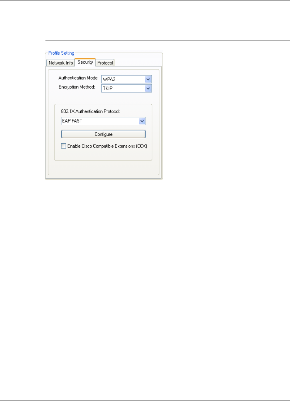
Marvell Wireless Configuration Utility User Interface
Profile Manager Tab
Copyright © 2007 Marvell CONFIDENTIAL Doc. No. MV-S800473-00 Rev. B
August 14, 2007, 2.00 Document Classification: Proprietary Information Page 49
3.2.4.5 802.1X / WPA / WPA2 with EAP-FAST
The definition of the EAP-FAST authentication protocol for the authentication modes 802.1X, WPA,
and WPA2 is identical:
1. Select EAP-FAST as 802.1X Authentication Protocol.
2. Click Configure.
The EAP-FAST Configuration window is displayed. For a detailed description of this window,
see Table 17 on page 51.
Figure 38: Security Tab—WPA2 with EAP-FAST
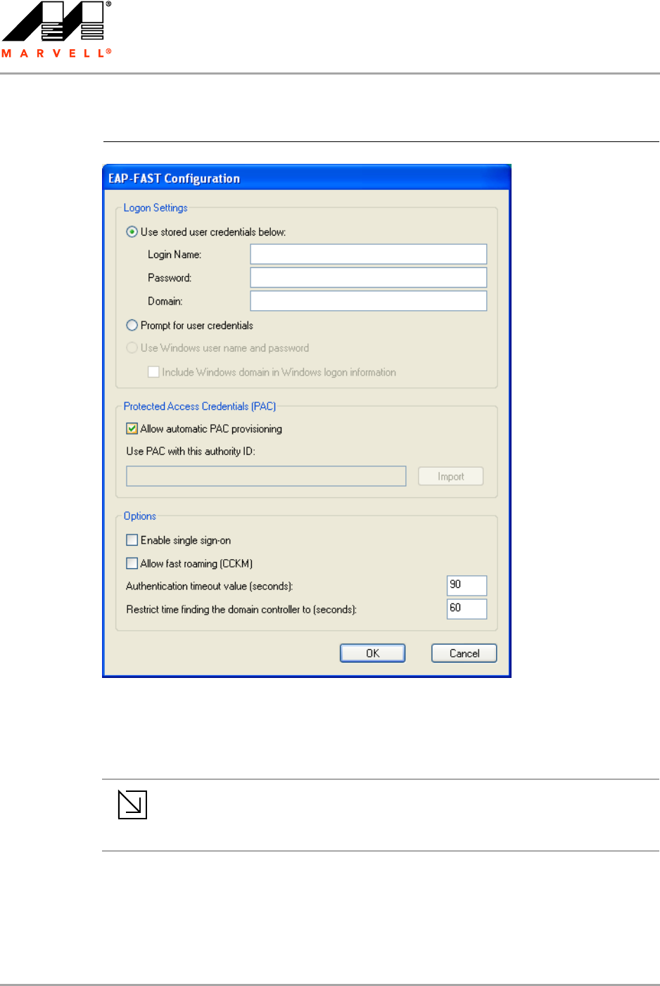
CB-82/MB-82/EC-82/MC-82
User Guide
Doc. No. MV-S800473-00 Rev. B CONFIDENTIAL Copyright © 2007 Marvell
Page 50 Document Classification: Proprietary Information August 14, 2007, 2.00
3. Under Logon Settings, select the user credentials (and, if required, Login Name, Password,
and Domain) to be used for the client authentication.
Use Windows user name and password is only available if Enable single-signon is
selected.
4. If automatic Protected Access Credentials (PAC) provisioning is required, select the Allow
Automatic PAC Provisioning check box, and enter the appropriate Authority ID.
5. If required, specific further settings under Options.
6. Click OK to return to the Security tab of the Profile Settings.
Figure 39: EAP-FAST Configuration Window
Note
To enable single sign-on, administrator rights are required.
Using single sign-on authentication for the first time requires a restart of your
system after having saved the EAP-FAST configuration.

Marvell Wireless Configuration Utility User Interface
Profile Manager Tab
Copyright © 2007 Marvell CONFIDENTIAL Doc. No. MV-S800473-00 Rev. B
August 14, 2007, 2.00 Document Classification: Proprietary Information Page 51
7. If CCX compatibility is required, select the Enable Cisco Compatible Extensions (CCX) check
box.
8. Click Save to set the configuration.
Table 17: EAP-FAST Configuration Window Description
Area/Button Description
Logon Settings Credentials to be used for login to the authentication server:
•Use stored user credentials below
•Login Name—Login name to the authentication server
•Password—Password for login to the authentication
server
•Domain—Domain name for login to the authentication
server (optional)
•Prompt for User Credentials
Credentials are to be entered during authentication (are not
stored in the profile).
•Use Windows user name and password (available only
when Enable single sign-on is selected)
Windows user name and password are used for login to the
authentication server. Additionally, Include Windows
domain in Windows logon information can be selected.
Protected Access Credentials
(PAC)
Allows automatic PAC provisioning
Import Selects authority ID of the authentication server
Options •Enable single sign-on
Windows user credentials are used for login to the
authentication server (see Logon Settings)
•Allow fast roaming (CCKM)
Enables Cisco Centralized Key Management (CCKM) which
allows for fast roaming without involving the authentication
server
•Authentication timeout value (seconds)
Time to be waited before assuming the authentication failed.
Default value is 90.
•Restrict time finding domain controller to (seconds)
Maximum time allowed to find the domain controller,
included in the overall authentication time. Default value
is 60.
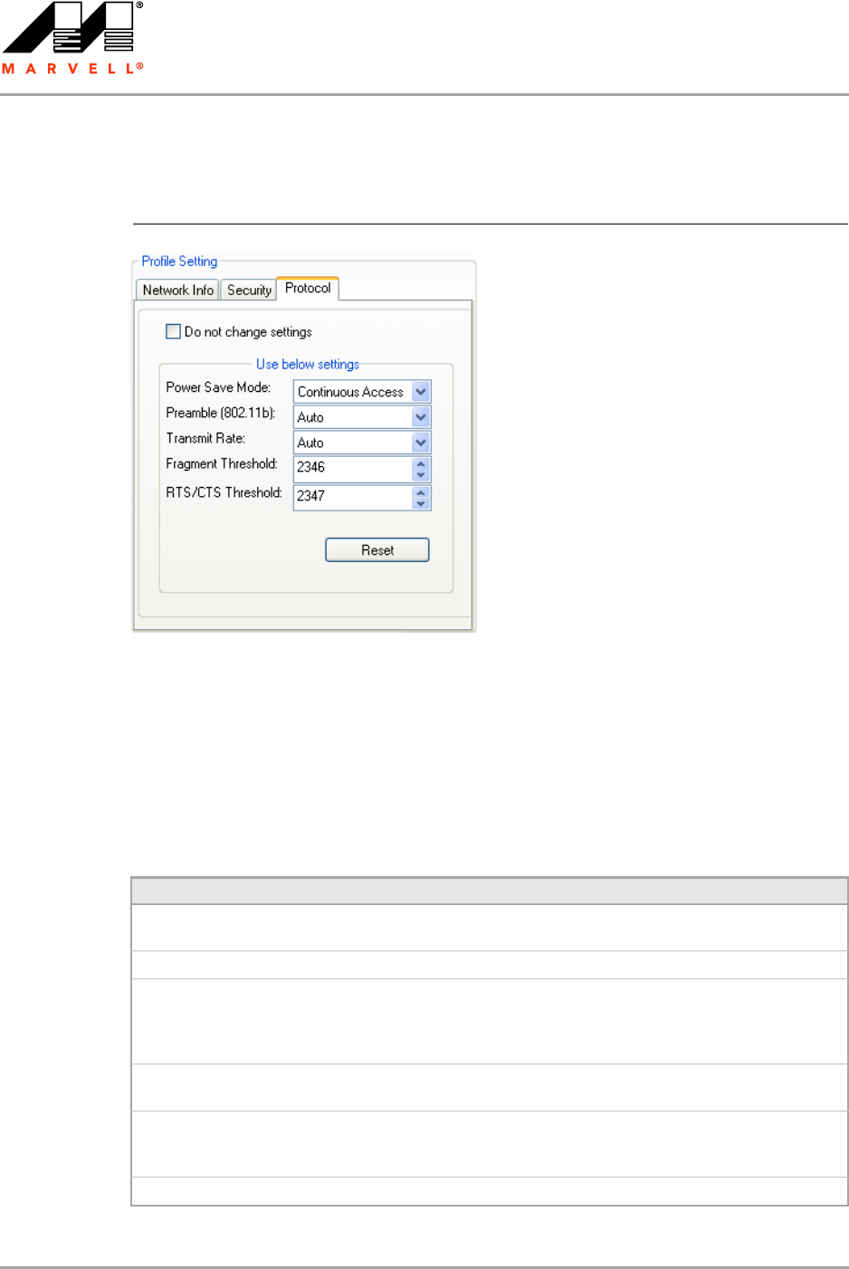
CB-82/MB-82/EC-82/MC-82
User Guide
Doc. No. MV-S800473-00 Rev. B CONFIDENTIAL Copyright © 2007 Marvell
Page 52 Document Classification: Proprietary Information August 14, 2007, 2.00
3.2.5 Profile Setting—Protocol Tab
The Protocol tab allows you to set or change the protocol information.
Do not change settings
If this check box is selected, the protocol setting is not changed when the profile is applied.
Use below settings
If the Do not change setting check box is not selected, the protocol settings include the following
parameters.
Figure 40: Protocol Tab
Table 18: Protocol Tab Description
Field Description
Power Save Mode Sets the power mode. Available options are Continuous Access or Max
Power Save. The default setting is Continuous Access.
Preamble (802.11b) Sets the Radio Preamble to Auto, Short or Long.
Transmit Rate The range of the data rate depends on the type of AP that the client card
is connected to. The default setting is Auto Select.
MCS index will be allowed to select when the 802.11n Network check
box in the Network Info tab is selected.
Fragment Threshold Sets the fragmentation threshold (the size that packets are fragmented
into for transmission). The default setting is 2346.
RTS/CTS Threshold Sets the packet size at which the AP issues a Request-To-Send (RTS) or
Clear-To-Send (CTS) frame before sending the packet. The default
setting is 2347.
Reset Resets the protocol settings to their default values
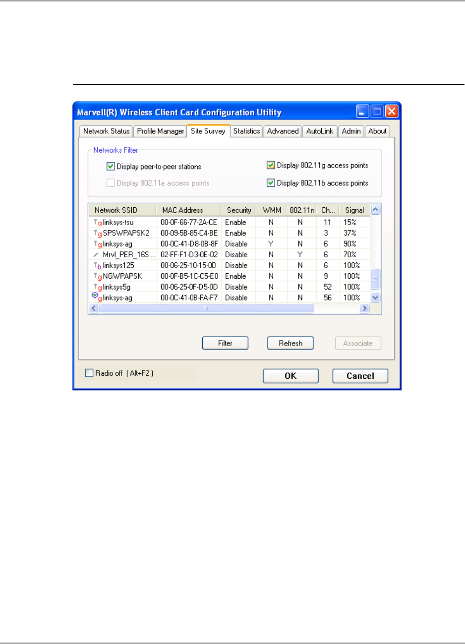
Marvell Wireless Configuration Utility User Interface
Site Survey Tab
Copyright © 2007 Marvell CONFIDENTIAL Doc. No. MV-S800473-00 Rev. B
August 14, 2007, 2.00 Document Classification: Proprietary Information Page 53
3.3 Site Survey Tab
The Site Survey tab displays a list of all peer-to-peer (Ad-Hoc) and AP stations within range of the
client card.
3.3.1 Site Survey—Networks Filter
This section lets you customize which sites are displayed in the Site Survey list:
Display Peer-To-Peer stations—selecting this check box displays all peer-to-peer (Ad-Hoc)
stations within range.
Display 802.11g Access Points—selecting this check box displays all 802.11g APs within
range.
Display 802.11b Access Points—selecting this check box displays all 802.11b APs within
range.
Figure 41: Site Survey Tab
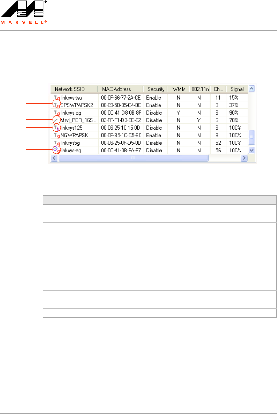
CB-82/MB-82/EC-82/MC-82
User Guide
Doc. No. MV-S800473-00 Rev. B CONFIDENTIAL Copyright © 2007 Marvell
Page 54 Document Classification: Proprietary Information August 14, 2007, 2.00
3.3.2 Site Survey—List of Detected Stations
This section reports information on the peer-to-peer (Ad-Hoc) stations or AP stations detected.
Figure 42: Site Survey—List of Detected Stations
802.11g AP Icon
802.11b AP Icon
Ad-Hoc Network
Circle means
connected
Table 19: List of Detected Stations Description
Field Description
Network SSID Network SSID label (i.e., the Network Name). The Network Name is a text string.
MAC Address MAC address, a hardware address that uniquely identifies each node of a network
Security Security enabled or disabled
CH Channel used by the detected device
Signal Signal strength of the detected device as a percentage
Icons The following icons may be displayed left of the Network SSID:
• An antenna icon with a subscript b indicates an 802.11b AP.
• An antenna icon with a subscript g indicates an 802.11g AP.
• A circle around the antenna icon means the client card is connected to this
network.
• A slash icon indicates an Ad-Hoc network.
WMM Wireless Multimedia Enhancements (WMM) supported by the detected device
EWC Draft-802.11n functionality supported by the detected device
Network Type Type of environment connected to: Ad-Hoc or Infrastructure
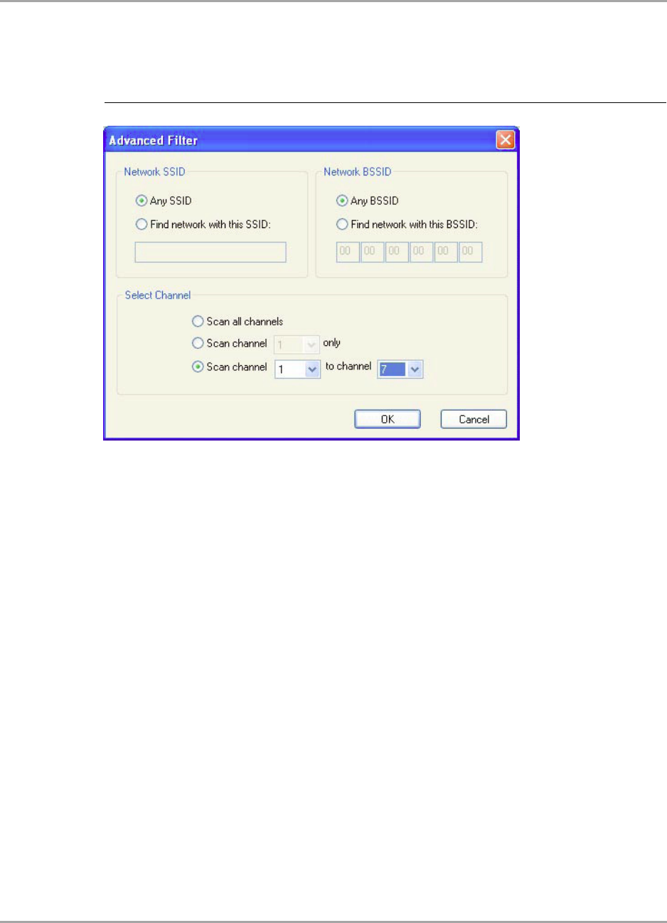
Marvell Wireless Configuration Utility User Interface
Site Survey Tab
Copyright © 2007 Marvell CONFIDENTIAL Doc. No. MV-S800473-00 Rev. B
August 14, 2007, 2.00 Document Classification: Proprietary Information Page 55
3.3.3 Site Survey—Filter Button
Clicking the Filter button displays the Advanced Filter window.
3.3.3.1 Network SSID
Any SSID—no specific SSID is used when scanning for available networks in the area.
Find network with this SSID—the utility searches for the specified SSID.
3.3.3.2 Network BSSID
Any BSSID—no specific BSSID is used when scanning for available networks in the area.
Find network with this BSSID—the utility searches for the specified BSSID.
3.3.3.3 Select Channel
Scan all channels—all channels are scanned when searching for available networks in the
area.
Scan channel Only—only the specified channel is scanned when searching for available
networks in the area.
Scan Channel to Channel—a range of channels are scanned when searching for available
networks in the area.
3.3.4 Site Survey—Refresh Button
To request a survey of the wireless networks in the area, click Refresh.
3.3.5 Site Survey—Associate Button
To establish a connection, select an available network, and then click Associate. Alternatively, the
connection can be established by double-clicking the selected network.
Figure 43: Site Survey—Advanced Filter Window
Note to US model owner: To comply with US FCC regulation, the country selection function has
been completely removed from all US models. The above function is for non-US models only.
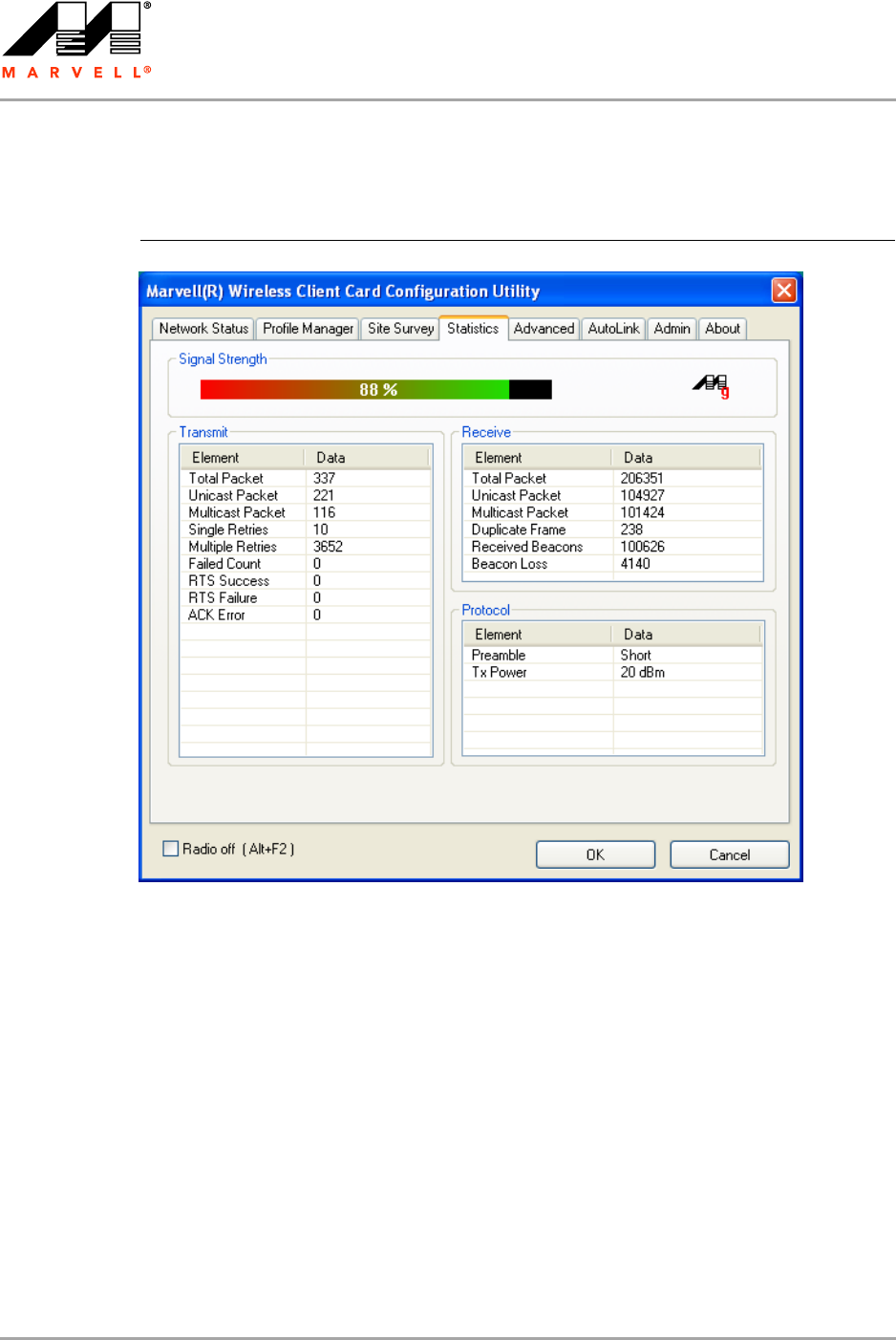
CB-82/MB-82/EC-82/MC-82
User Guide
Doc. No. MV-S800473-00 Rev. B CONFIDENTIAL Copyright © 2007 Marvell
Page 56 Document Classification: Proprietary Information August 14, 2007, 2.00
3.4 Statistics Tab
Clicking the Statistics tab displays the statistics of the current connect session.
3.4.1 Signal Strength
The color-coded Signal Strength bar displays the signal strength of the last packet received by the
client card. Signal strength is reported as a percentage. A signal in the red indicates a bad
connection. A signal in the green indicates a good connection.
Figure 44: Statistics Tab
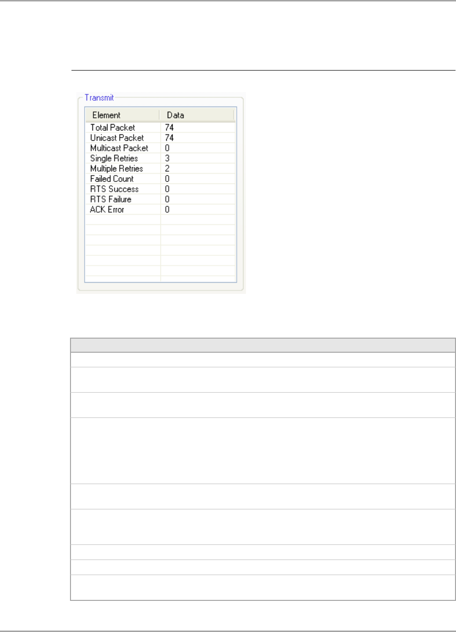
Marvell Wireless Configuration Utility User Interface
Statistics Tab
Copyright © 2007 Marvell CONFIDENTIAL Doc. No. MV-S800473-00 Rev. B
August 14, 2007, 2.00 Document Classification: Proprietary Information Page 57
3.4.2 Transmit Section
The Transmit section displays the information on the packets sent.
Figure 45: Transmit Section
Table 20: Transmit Section Description
Field Description
Total Packet Reports the total number of packets transmitted
Unicast Packet Reports the number of packets transmitted by the client card that were
destined for a single network node
Multicast Packet Reports the number of packets transmitted by the client card that were
destined for more than one network node
Single Retries Reports the number of packets that require one retry before the client card
received an acknowledgement.
NOTE: After the client card sends a packet, it waits for an acknowledge
from the receiving radio to confirm that the packet was
successfully received. If the acknowledge is not received within a
specified period of time, the client card retransmits the packet.
Multiple Retries Reports the number of packets that require more than one retry before the
client card received an acknowledgement
Failed Count Reports the number of packets that were not successfully transmitted
because the client card did not receive an acknowledge within the
specified period of time
RTS Success Reports the number of RTS attempts that were successful
RTS Failure Reports the number of RTS attempts that were not successful
ACK Error Reports the number of unicast transmit attempts for which no
acknowledgement was received
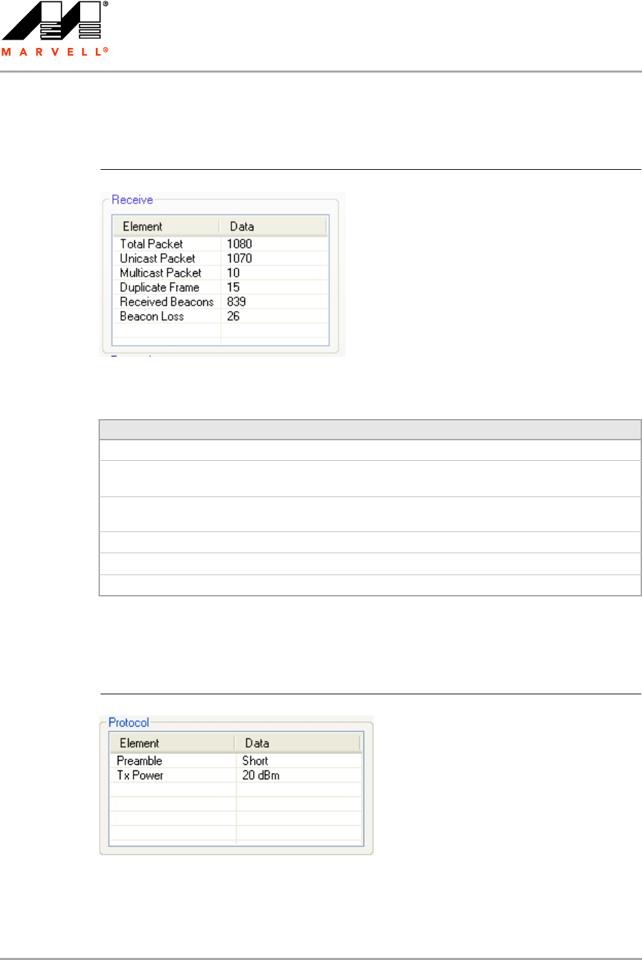
CB-82/MB-82/EC-82/MC-82
User Guide
Doc. No. MV-S800473-00 Rev. B CONFIDENTIAL Copyright © 2007 Marvell
Page 58 Document Classification: Proprietary Information August 14, 2007, 2.00
3.4.3 Receive Section
The Receive section displays the information on the packets received.
3.4.4 Protocol Section
The Protocol section displays the information on the protocol status.
Figure 46: Receive Section
Table 21: Receive Section Description
Field Description
Total Packet Reports the total number of packets received
Unicast Packet Reports the number of packets received by the client card that were
destined for a single network node
Multicast Packet Reports the number of packets received by the client card that were
destined for more than one network node
Duplicate Frame Reports the number of duplicate frames received
Received Beacons Reports the number of beacons received after association is established
Beacon Loss Reports the number of missing beacons after association is established
Figure 47: Protocol Section
18
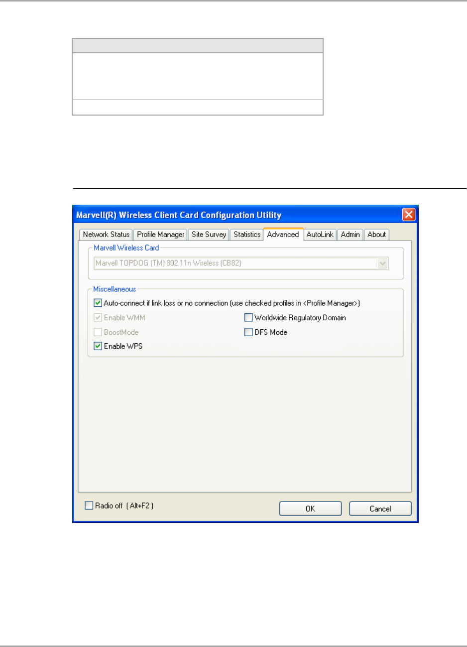
Marvell Wireless Configuration Utility User Interface
Advanced Tab
Copyright © 2007 Marvell CONFIDENTIAL Doc. No. MV-S800473-00 Rev. B
August 14, 2007, 2.00 Document Classification: Proprietary Information Page 59
3.5 Advanced Tab
The Advanced tab displays the advanced parameters available for the installed Marvell client cards.
3.5.1 Advanced Tab—Marvell Wireless Card
This section of the Advanced tab reports the type of Marvell client card installed.
Table 22: Protocol Section Description
Field Description
Preamble Displays radio preamble type:
•Auto
• Short
•Long
Tx Power Displays transmit power mode (in dBm)
Figure 48: Advanced Tab
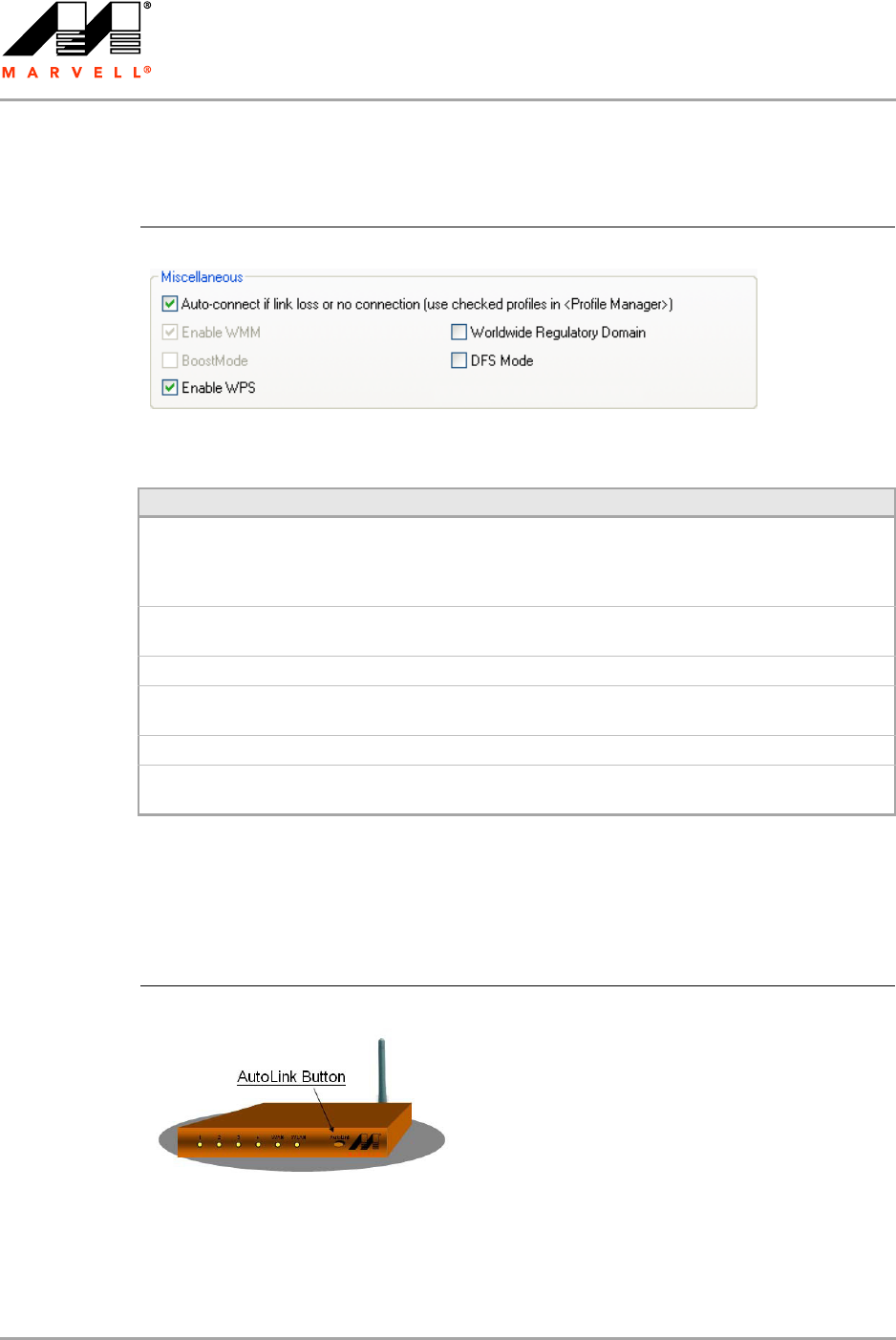
CB-82/MB-82/EC-82/MC-82
User Guide
Doc. No. MV-S800473-00 Rev. B CONFIDENTIAL Copyright © 2007 Marvell
Page 60 Document Classification: Proprietary Information August 14, 2007, 2.00
3.5.2 Advanced Tab—Miscellaneous
3.6 AutoLink Tab
To enable AutoLink mode, proceed as follows:
1. Toggle the AutoLink button on the Access Point to enable AutoLink mode.
Figure 49: Miscellaneous Section
Table 23: Advanced Tab Miscellaneous Section Description
Field Description
Auto connect if link loss or no
connection (use checked profiles in
<Profile Manager>)
Clear this check box to disable the auto-configuration feature.
Whenever there is a link loss, auto-configuration tries to
establish a connection to the checked profiles in the Profile
Manager window.
Enable WMM Select this check box to enable/disable the Wireless Multimedia
Enhancements (WMM) feature.
BoostMode Select this check box for performance enhancement.
Enable WPS Select this check box to enable Wireless Provisioning Services
(WPS).
Worldwide Regulatory Domain Select this check box to set the regulatory domain
DFS Mode Select this check box to enable Dynamic Frequency Selection
(DFS)
Figure 50: Access Point AutoLink Button
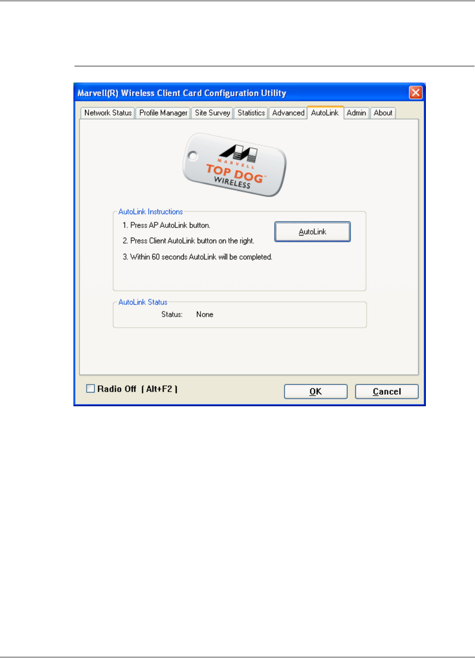
Marvell Wireless Configuration Utility User Interface
AutoLink Tab
Copyright © 2007 Marvell CONFIDENTIAL Doc. No. MV-S800473-00 Rev. B
August 14, 2007, 2.00 Document Classification: Proprietary Information Page 61
2. On the AutoLink tab, click AutoLink.
Within 60 seconds, the AutoLink will be completed.
Figure 51: AutoLink Tab
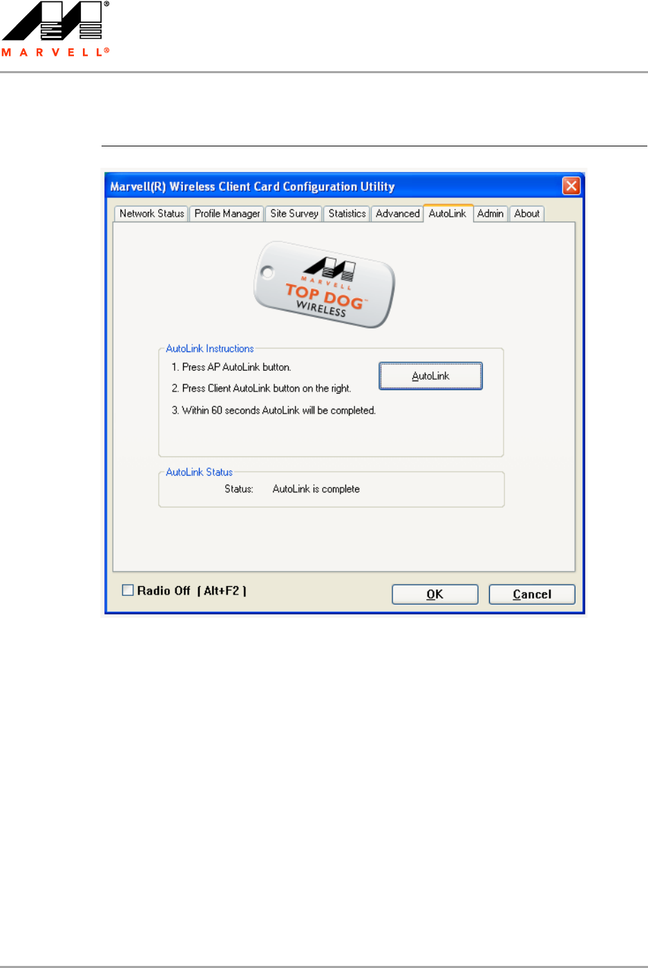
CB-82/MB-82/EC-82/MC-82
User Guide
Doc. No. MV-S800473-00 Rev. B CONFIDENTIAL Copyright © 2007 Marvell
Page 62 Document Classification: Proprietary Information August 14, 2007, 2.00
AutoLink is complete.
Figure 52: AutoLink Tab (AutoLink Complete)
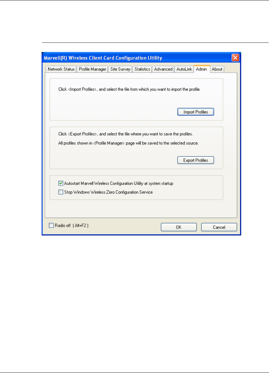
Marvell Wireless Configuration Utility User Interface
Admin Tab
Copyright © 2007 Marvell CONFIDENTIAL Doc. No. MV-S800473-00 Rev. B
August 14, 2007, 2.00 Document Classification: Proprietary Information Page 63
3.7 Admin Tab
The Admin tab allows you to import and export profiles.
3.7.1 Admin Tab—Import Profiles
To import a profile, proceed as follows:
1. Click Import Profiles.
2. Select the path and filename of the profile.
3. Click Open.
3.7.2 Admin Tab—Export Profiles
To export a profile, proceed as follows:
1. Click Export Profiles.
2. Select or enter the path and filename of the profile.
3. Click Save.
Figure 53: Admin Tab
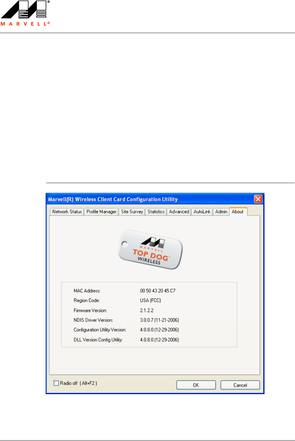
CB-82/MB-82/EC-82/MC-82
User Guide
Doc. No. MV-S800473-00 Rev. B CONFIDENTIAL Copyright © 2007 Marvell
Page 64 Document Classification: Proprietary Information August 14, 2007, 2.00
3.7.3 Admin Tab—Autostart Marvell Wireless Configuration
Utility
Select the Autostart Marvell Wireless Client Card Configuration Utility at System Startup check
box to automatically start the Marvell Wireless Configuration Utility at system startup
(recommended).
3.7.4 Admin Tab—Stop Windows Wireless Zero Configuration
Service
When using the Marvell Wireless Configuration Utility, Marvell recommends turning off the Windows
Wireless Zero Configuration Service, which is enabled by default. Both utilities should not be used at
the same time. To turn off the Windows Wireless Zero Configuration Service, select the Stop
Windows Wireless Zero Configuration Service check box.
3.8 About Tab
The About tab displays information about the Marvell Wireless Client Card Configuration Utility.
Figure 54: About Tab

Compliance Statements
Federal Communications Commission (FCC) Compliance
Copyright © 2007 Marvell CONFIDENTIAL Doc. No. MV-S800473-00 Rev. B
August 14, 2007, 2.00 Document Classification: Proprietary Information Page 65
A Compliance Statements
A.1 Federal Communications Commission (FCC)
Compliance
This equipment has been tested and found to comply with the limits for a Class B digital device,
pursuant to Part 15 of FCC Rules. These limits are designed to provide reasonable protection
against harmful interference in a residential installation. This equipment generates, uses, and can
radiate radio frequency energy. If not installed and used in accordance with the instructions, it may
cause harmful interference to radio communications. However, there is no guarantee that
interference will not occur in a particular installation.
If this equipment does cause harmful interference to radio or television reception, which can be
determined by tuning the equipment off and on, the user is encouraged to try and correct the
interference by one or more of the following measures:
Reorient or relocate the receiving antenna.
Increase the distance between the equipment and the receiver.
Connect the equipment to outlet on a circuit different from that to which the receiver is
connected.
Consult the dealer or an experienced radio/TV technician for help.
Modifications
Any changes or modifications not expressly approved by the party responsible for compliance could
void the user's authority to operate the equipment.
A.2 Industry Canada Notice
This device complies with Canadian RSS-210.
“This Class B digital apparatus complies with Canadian ICES-003”
Cet appareil numérique de la classe B est conforme à la norme NMB-003 du Canada
Operation is subject to the following two conditions: (1) this device may not cause interference, and
(2) this device must accept any interference, including interference that may cause undesired
operation of this device.”
L'utilisation de ce dispositif est autorisée seulement aux conditions suivantes : (1) il ne doit pas
produire de brouillage et (2) l'utilisateur du dispositif doit étre prêt à accepter tout brouillage
radioélectrique reçu, même si ce brouillage est susceptible de compromettre le fonctionnement du
dispositif.
The term “IC” before the equipment certification number only signifies that the Industry Canada
technical specifications were met.
To reduce potential radio interference to other users, the antenna type and its gain should be so
chosen that the equivalent isotropically radiated power (EIRP) is not more than that required for
successful communication.
To prevent radio interference to the licensed service, this device is intended to be operated indoors
and away from windows to provide maximum shielding. Equipment (or its transmit antenna) that is
installed outdoors is subject to licensing.
This equipment has been tested and found to comply with the limits for a Class B digital device, pursuant to Part
15 of the FCC Rules. These limits are designed to provide reasonable protection against harmful interference in a
residential installation. This equipment generates, uses and can radiate radio frequency energy and, if not
installed and used in accordance with the instructions, may cause harmful interference to radio communications.
However, there is no guarantee that interference will not occur in a particular installation. If this equipment does
cause harmful interference to radio or television reception, which can be determined by turning the equipment off
and on, the user is encouraged to try to correct the interference by one of the following measures:
- Reorient or relocate the receiving antenna.
- Increase the separation between the equipment and receiver.
- Connect the equipment into an outlet on a circuit different from that
to which the receiver is connected.
- Consult the dealer or an experienced radio/TV technician for help.
This device complies with Part 15 of the FCC Rules. Operation is subject to the following two conditions: (1) This
device may not cause harmful interference, and (2) this device must accept any interference received, including
interference that may cause undesired operation.
FCC Caution: Any changes or modifications not expressly approved by the party responsible for compliance could
void the user's authority to operate this equipment.
IMPORTANT NOTE:
FCC Radiation Exposure Statement:
This equipment complies with FCC radiation exposure limits set forth for an uncontrolled environment. This
equipment should be installed and operated with minimum distance 20cm between the radiator & your body.
This transmitter must not be co-located or operating in conjunction with any other antenna or transmitter.
IEEE 802.11b or 802.11g operation of this product in the U.S.A. is firmware-limited to channels 1 through 11.
This device is intended only for OEM integrators under the following conditions:
1) The antenna must be installed such that 20 cm is maintained between the antenna and users, and
2) The transmitter module may not be co-located with any other transmitter or antenna,
3) For all products market in US, OEM has to limit the operation channels in CH1 to CH11 for 2.4G band by
supplied firmware programming tool. OEM shall not supply any tool or info to the end-user regarding to Regulatory
Domain change.
As long as 3 conditions above are met, further transmitter test will not be required. However, the OEM integrator is
still responsible for testing their end-product for any additional compliance requirements required with this module
installed (for example, digital device emissions, PC peripheral requirements, etc.).
IMPORTANT NOTE: In the event that these conditions can not be met (for example certain laptop configurations
or co-location with another transmitter), then the FCC authorization is no longer considered valid and the FCC ID
can not be used on the final product. In these circumstances, the OEM integrator will be responsible for re-
evaluating the end product (including the transmitter) and obtaining a separate FCC authorization.
End Product Labeling
This transmitter module is authorized only for use in device where the antenna may be installed such that 20 cm
may be maintained between the antenna and users. The final end product must be labeled in a visible area with
the following: “Contains FCC ID: MCL74487504”.
Manual InformationTo the End User
The OEM integrator has to be aware not to provide information to the end user regarding how to install or remove
this RF module in the user's manual of the end product which integrates this module.
The end user manual shall include all required regulatory information/warning as show in this manual.
CB-82/MB-82/EC-82/MC-82
User Guide
Doc. No. MV-S800473-00 Rev. B CONFIDENTIAL Copyright © 2007 Marvell
Page 66 Document Classification: Proprietary Information August 14, 2007, 2.00
A.3 Europe—EU Declaration of Conformity and
Restrictions
Hereby, Marvell Semiconductor, Inc., declares that this telecommunication equipment complies with
all the provisions of the EC directives listed below and meets the relevant parts of the related
technical specifications:
Compliance with R&TTE (Radio & Telecommunications Terminal Equipment) Directive 99/5/EC,
Article 10.5
EN 300 328 v1.6.1 (2004-11) – Electromagnetic compatibility and Radio spectrum Matters
(ERM); Wideband Transmission Systems; Data transmission equipment operating in the
2,4GHz ISM band and using spread spectrum modulation techniques; Harmonized EN covering
essential requirements under article 3.2 of the R&TTE directive.
Compliance with Electromagnetic Compatibility (EMC) Directive 89/336/EEC
EN 301 489-17 v1.2.1 (2002-08) – Electromagnetic compatibility and Radio Spectrum Matters
(ERM); Electromagnetic Compatibility (EMC) standard for radio equipment and services;
Part 17: Specific conditions for wideband data and high performance RLAN (HIPERLAN)
equipment.
Compliance with Low Voltage Directive 73/23/EEC
EN 60950:2001 – Safety of Information Technology Equipment, including electrical business
equipment.
EN 50371:2002 – Generic standard to demonstrate the compliance of low power electronic and
electric apparatus with the basic restrictions related to human exposure to electromagnetic
fields.
EN 50385:2002 – Product standard to demonstrate the compliances of radio base stations and
fixed terminal stations for wireless telecommunication systems with the basic restrictions or the
reference levels related to human exposure to radio frequency electromagnetic fields.
This equipment is marked with the 0984 symbol and can be used throughout the
European community.
Marking by the symbol indicates that usage restrictions apply.
2.4 GHz for Metropolitan France
In all Metropolitan départements, wireless LAN frequencies can be used under the following
conditions, either for public or private use:
Indoor use: maximum power (EIRP) of 100 mW for the entire 2400 - 2483.5 MHz frequency
band
Outdoor use: maximum power (EIRP) of 100 mW for the 2400 - 2454 MHz band and with
maximum power (EIRP) of 10 mW for the 2454 - 2483 MHz band
Caution
Exposure to Radio Frequency Radiation
To comply with RF exposure compliance requirements, a separation distance of at least
20 cm must be maintained between the antenna of this device and all persons. This
device must not be co-located or operating in conjunction with any other antenna or
transmitter.
A.2

Compliance Statements
Taiwan DGT
Copyright © 2007 Marvell CONFIDENTIAL Doc. No. MV-S800473-00 Rev. B
August 14, 2007, 2.00 Document Classification: Proprietary Information Page 67
A.4 Taiwan DGT
2.4 GHz Band Products
NCC
「本產品內含射頻模組:XXXyyyLPDzzzz-x
A.3
A.4
Industry Canada Statement
This device complies with RSS-210 of the Industry Canada Rules. Operation is subject to the following two
conditions:
1) this device may not cause interference and
2) this device must accept any interference, including interference that may cause undesired operation of the
device
This device has been designed to operate with an antenna having a maximum gain of 1.51dBi.
Antenna having a higher gain is strictly prohibited per regulations of Industry Canada. The required antenna
impedance is 50 ohms.
To reduce potential radio interference to other users, the antenna type and its gain should be so chosen that the
EIRP is not more than required for successful communication.
IMPORTANT NOTE:
IC Radiation Exposure Statement:
This equipment complies with IC radiation exposure limits set forth for an uncontrolled environment. This
equipment should be installed and operated with minimum distance 20cm between the radiator & your body.
This device is intended only for OEM integrators under the following conditions:
1) The antenna must be installed such that 20 cm is maintained between the antenna and users, and
2) The transmitter module may not be co-located with any other transmitter or antenna,
3) For all products market in Canada, OEM has to limit the operation channels in CH1 to CH11 for 2.4G band by supplied
firmware programming tool. OEM shall not supply any tool or info to the end-user regarding to Regulatory Domain change.
As long as 3 conditions above are met, further transmitter test will not be required. However, the OEM integrator is still
responsible for testing their end-product for any additional compliance requirements required with this module installed (for
example, digital device emissions, PC peripheral requirements, etc.).
IMPORTANT NOTE: In the event that these conditions can not be met (for example certain laptop configurations or co-location
with another transmitter), then the IC authorization is no longer considered valid and the IC ID can not be used on the final
product. In these circumstances, the OEM integrator will be responsible for re-evaluating the end product (including the
transmitter) and obtaining a separate IC authorization.
End Product Labeling
This transmitter module is authorized only for use in device where the antenna may be installed such that 20 cm may be
maintained between the antenna and users. The final end product must be labeled in a visible area with the following: “Contains
IC: 2878D-74487504”.
Manual InformationTo the End User
The OEM integrator has to be aware not to provide information to the end user regarding how to install or remove this RF module
in the user's manual of the end product which integrates this module.
The end user manual shall include all required regulatory information/warning as show in this manual.
2.42