HON HAI PRECISION IND J20H076 802.11abgn wireless module User Manual
HON HAI Precision Ind. Co., Ltd. 802.11abgn wireless module
User Manual.pdf
1
1.Level1Environment‐relatedSubstancesshouldNEVERbeused.
2.Purchaseink,paint,wirerods,andmoldingresinsonlyfromthebusinesspartnersthat
SonyapprovesasGreenPartners.
3.RecycledResinandCoatedWireshouldbeprocuredfromGreenPartners
UserManual
IEEE802.11a/b/g/n2x2WiFiModule
ProjectNameQCA9375IEEE802.11a/b/g/n2x2WiFiModule
CustomerPartNo. 021430401
ApprovalSheetRev.1.0
FoxconnPartNo.J20H076.01
PreparedbyReviewedbyApprovedby
GallonG.R.TaoRobinXu Chang‐FuLin
HON HAI PRECISION IND. CO., LTD.
No.2, 2nd Dong Huan Road, 10th
YouSong lndustrial District, Longhua
Town, Baoan, ShenZhen
802.11abgn wireless module
802.11abgn wireless module

2
CONTENTS
1. REVISION HISTORY ..................................................................... 3
2 PRODUCT OVERVIEW ................................................................... 4
3 SIGNAL DESCRIPTION .................................................................. 5
3.1 SIGNAL DIAGRAM ........................................................................5
3.2 PINOUTS...............................................................................5
3.2.1 Connector Specification
.............................................................5
3.2.2 Pin definition
......................................................................5
4 ELECTRICAL SPECIFICATION............................................................ 6
4.1 ABSOLUTE MAXIMUM RATING ..............................................................6
4.2 RECOMMENDED OPERATING CONDITION .....................................................6
4.3 POWER CONSUMPTION ...................................................................6
4.4 POWER UP SEQUENCE ...................................................................6
4.5 WLAN RF SPECIFICATIONS ...............................................................7
4.5.1 WLAN RF Specification- 802.11b
.....................................................7
4.5.2 WLAN RF Specification- 802.11g
.....................................................8
4.5.3 WLAN RF Specification- 802.11n (2.4GHz) HT20
.......................................9
4.5.4 WLAN RF Specification- 802.11a
....................................................10
4.5.5 WLAN RF Specification- 802.11n (5GHz) HT20
.......................................11
4.5.6 WLAN RF Specification- 802.11n (5GHz) HT40
.......................................12
5 SCHEMATIC AND PCB LAYOUT ......................................................... 13
5.1 MODULE SCHEMATIC ....................................................................13
5.2 MODULE PCB LAYOUT ..................................................................15
5.2.1 PCB Stack-up
....................................................................15
5.2.2 Component Placement
.............................................................15
5.2.3 PCB Layout
......................................................................16
6 ANTENNA SPECIFICATIONS ............................................................ 18
6.1 PCB PRINTED ANTENNA PATTERN .........................................................18
6.2 ANTENNA RADIATION PERFORMANCE.......................................................18
7 MODULE MECHANICAL SPECIFICATIONS ............................................... 21
8 HANDLING NOTICE .................................................................... 22
9 RELIABILITY TEST PLAN ............................................................... 23
10 MARKING INFORMATION ............................................................... 25
11 PACKING INFORMATION ............................................................... 26

3
1. Revision History
DateDocumentrevisionChangeHistory
2013/5/241.0Initialrelease

!
5!
2 Product Overview
This documentation outlines the QCA9375 WiFi Module. It is 802.11a/b/g/n compatible, ARIB STD-T66
Compatible; the module Host I/F is USB 2.0.
IEEE 802.11 a/b/g and 802.11n payload data rates for Wireless Local Area Network (WLAN).
1.1 Operating Frequency: 2402~2483.5MHz, 5150MHz~5250MHz, 5250MHz~5350MHz,
5470MHz~5725MHz, 5725MHz~5845MHz
1.2 Modulation: DBPSK, DQPSK, CCK, BPSK, QPSK, 16QAM, 64QAM
1.3 Data Rates: 1/2/5.5/11Mbps (11b)
6/9/12/18/24/36/48/54 Mbps (11g)
MCS0~MCS15
1.4 Security: it supports WEP, TKIP, AES, WPA/WPA2 and WAPI
1.5 Full 802.11e QoS support including WMM.
1.6 Support Short Guard interval and Frame aggregation with A-MPDU
The module is designed with a WTB (Wire to Board) connector to connect to host. Dimension is 40.0mm
x37.5mm x 5.45mm (typical).
Below figure1 shows functional block diagram of the WLAN module.
Figure 1: Module Functional Block Diagram
!
6!
3 Signal Description
3.1 Signal Diagram
Below figure 2 shows its signal diagram.
Figure 2: Module Signal Diagram
3.2 Pinouts
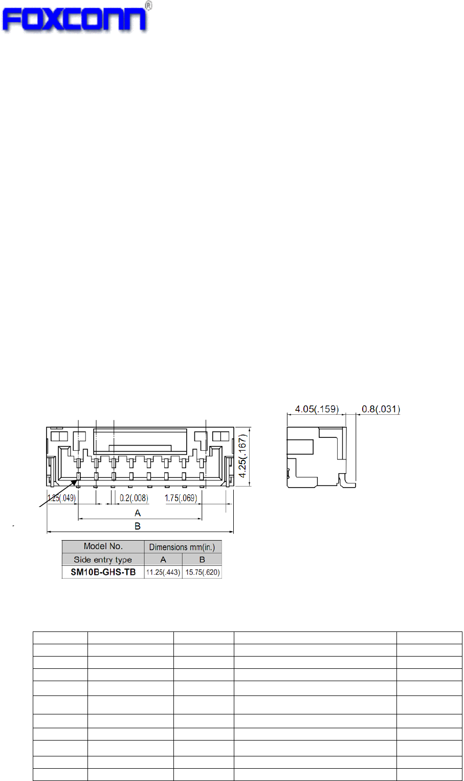
3.2.1 Connector Specification
JST WTB connector, Part Number: SM10B-GHS-TB(LF)!
3.2.2 Pin definition
Pin# Pin Name Pin Type Description Remark
1 GND - Ground
2 WoW O Wake-up on wireless LAN Active high
3 CHIP_PWD_L I Reset to module Active low
4 GND -
Ground
5 USB_DM I/O
USB differential signal negative
6 USB_DP I/O
USB differential signal positive
7 VCC_3.3V Power 3.3V power supply +/-5%
8 VCC_3.3V Power
3.3V power supply +/-5%
9 GND -
Ground
10 GND - Ground
Pin1
6
4 Electrical Specification
4.1 Absolute Maximum Rating
Symbol Condition Min. Typ. Max Unit
VCC_3.3V Respect to GND -0.3 3.3 3.6 V
CHIP_PWD_L Respect to GND -0.3 3.3 3.6 V
Max Ripple on Supplied Voltage 3.3V 165 mVpp
Operating Temperature -- -10 25 75 ℃
Storage Temperature -- -40 25 85 ℃
4.2 Recommended Operating Condition
Symbol Condition Min. Typ. Max Unit
VCC_3.3V Respect to GND 3.14 3.3 3.46 V
CHIP_PWD_L Respect to GND -0.3 3.3 3.46 V
4.3 Power Consumption
Symbol Condition Min Typ. Max Unit
Supply voltage 3.0 3.3 3.6 V
Tx Current(1Mbps/16dBm,MIMO) -- 465 -- mA
Tx Current(11g: 54Mbps/14.5dBm,MIMO) -- 400 -- mA
Tx Current(11gn: MCS15/13dBm/HT20,MIMO) -- 380 -- mA
Tx Current(11a: 6Mbps/15dBm,MIMO) -- 630 -- mA
Tx Current(11a: 54Mbps/12dBm,MIMO) -- 490 -- mA
Tx Current(11an: MCS15/10dBm/HT40,MIMO) -- 425 -- mA
Rx Current: 2.4GHz -- 120 -- mA
3.3V
Rx Current: 5GHz -- 130 -- mA
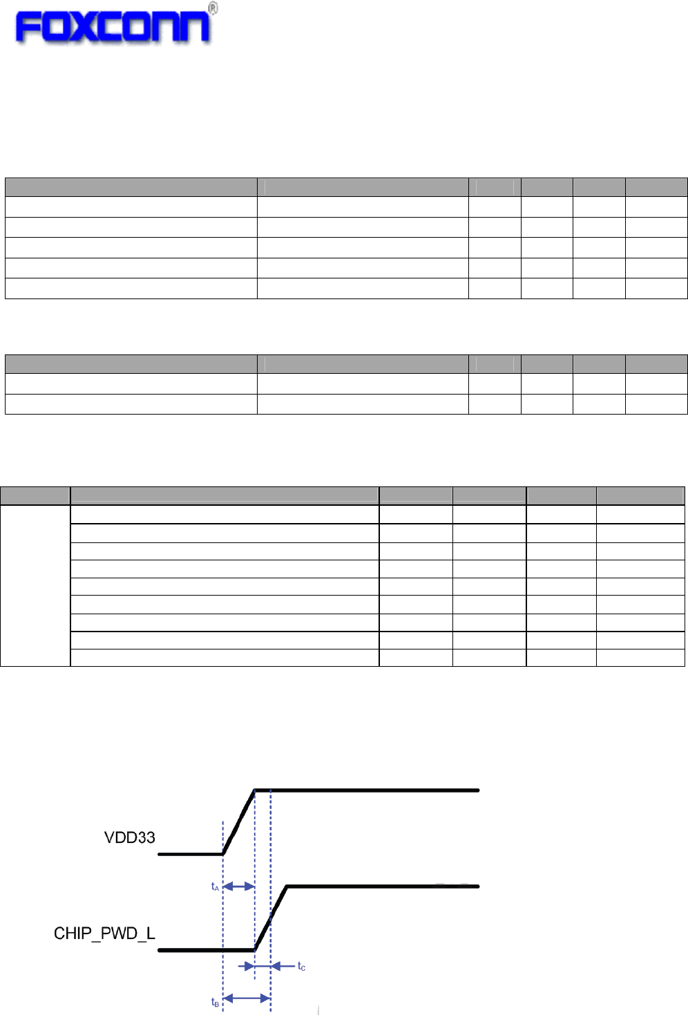
4.4 Power Up Sequence
Powerup(reset)timingisshownasbelow:
WhenhostprocessorcontrolstheCHIP_PWD_Lresetpin,thenallpowersuppliesshouldbe
stableforminimumof5μsbeforeCHIP_PWD_Lisde‐asserted.
7
ParameterDescriptionMinMaxUnit
tARisetimeofVDD3.3Vgoto90%of3.3V‐25ms
tCTimefromVDD3.3Vreaching90%of3.3Vtolevelof
CHIP_PWD_Lgoingabove50%ofVDD3.3V.
5‐ μs
tBThevalueistA+tC,duringthistime,thelevelof
CHIP_PWD_Lshouldstaybelow50%ofVDD3.3V.
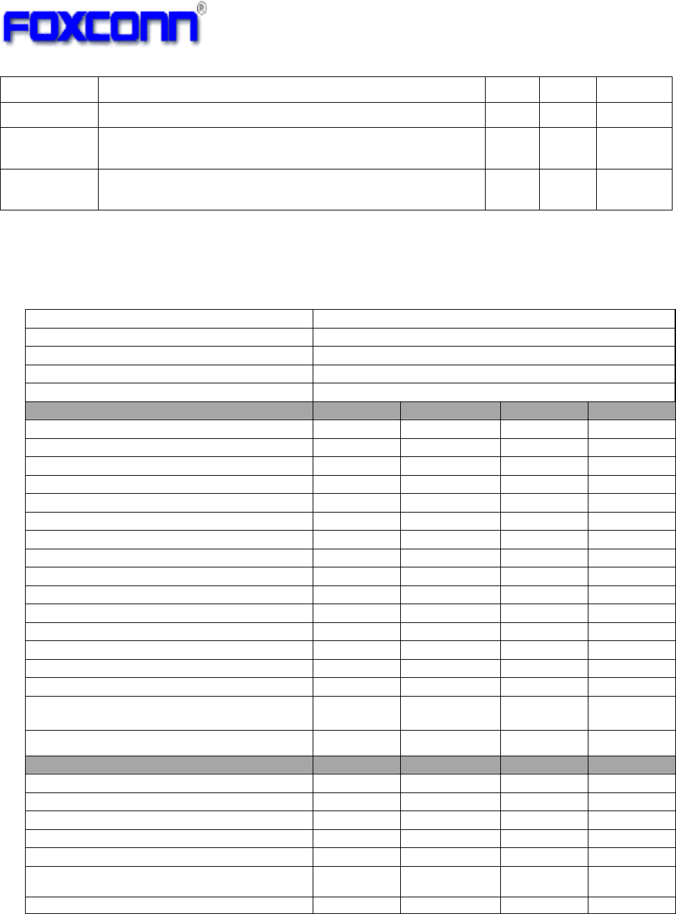
4.5 WLAN RF Specifications
4.5.1 WLAN RF Specification- 802.11b
Items Contents
Specification IEEE 802.11b
Mode DSSS / CCK
Channel CH1 to CH13
Data rate 1, 2, 5.5, 11Mbps
TX Characteristics Min. Typ. Max. Unit
1. Power Levels (per chain)
1) Target Power@1Mbps 14.5 16a 17.5 dBm
2) Target Power@2Mbps
14.5 16a 17.5 dBm
3) Target Power@5.5Mbps
14.5 16a 17.5 dBm
4) Target Power@11Mbps
14.5 16a 17.5 dBm
2. Spectrum Mask @ Target Power
1) fc-33MHz < f < fc-22MHz - - -50 dBr
2) fc-22MHz < f < fc-11MHz - - -30 dBr
3) fc+11MHz < f < fc+22MHz - - -30 dBr
4) fc+22MHz < f < fc+33MHz - - -50 dBr
3. Frequency Error -10 - +10 ppm
4. Modulation Accuracy(EVM)@ Target Power
1) 1Mbps - - -10 dB
2) 2Mbps - - -10 dB
3) 5.5Mbps - - -10 dB
4) 11Mbps - - -10 dB
5. Tx spurious emission - - -52 dBm
RX Characteristics Min. Typ. Max. Unit
6. Minimum Input Level Sensitivity
1) 1Mbps (FER≦8%) - -97 -92 dBm
2) 2Mbps (FER≦8%) - -94 -89 dBm
3) 5.5Mbps (FER≦8%) - -90 -85 dBm
4) 11Mbps (FER≦8%) - -87 -82 dBm
7. Maximum Input Level (FER≦8%) -10 0 - dBm
8. Rx spurious emission -65 dBm
a: 2412MHz target power reduced to 15dBm for FCC bandedge limit.

8
4.5.2 WLAN RF Specification- 802.11g
Items Contents
Specification IEEE 802.11g
Mode OFDM
Channel CH1 to CH13
Data rate 6, 9, 12, 18, 24, 36, 48, 54Mbps
TX Characteristics Min. Typ. Max. Unit
1. Power Levels (per chain)
1) Target Power@6Mbps
14.5 16b 17.5 dBm
2) Target Power@9Mbps
14.5 16b 17.5 dBm
3) Target Power@12Mbps
14.5 16b 17.5 dBm
4) Target Power@18Mbps
14.5 16b 17.5 dBm
5) Target Power@24Mbps
14.5 16b 17.5 dBm
6) Target Power@36Mbps
13.5 15b 16.5 dBm
7) Target Power@48Mbps
13.5 15b 16.5 dBm
8) Target Power@54Mbps
12.5 14b 15.5 dBm
2. Spectrum Mask @ Target Power
1) at fc +/- 11MHz - - -20 dBr
2) at fc +/- 20MHz - - -28 dBr
3) at fc > +/-30MHz - - -40 dBr
3. Modulation Accuracy(EVM)@ Target Power
1) 6Mbps - - -5 dB
2) 9Mbps - - -8 dB
3) 12Mbps - - -10 dB
4) 18Mbps - - -13 dB
5) 24Mbps - - -16 dB
6) 36Mbps - - -19 dB
7) 48Mbps - - -22 dB
8) 54Mbps - - -25 dB
4. Frequency Error -10 - +10 ppm
5. Tx spurious emission - - -54 dBm
RX Characteristics Min. Typ. Max. Unit
6. Minimum Input Level Sensitivity
1) 6Mbps (PER <10%) - -91 -84 dBm
2) 9Mbps (PER < 10%) - -89 -83 dBm
3) 12Mbps (PER < 10%) - -87 -81 dBm
4) 18Mbps (PER < 10%) - -84 -79 dBm
5) 24Mbps (PER < 10%) - -82 -76 dBm
6) 36Mbps (PER < 10%) - -80 -73 dBm
7) 48Mbps (PER < 10%) - -78 -70 dBm
8) 54Mbps (PER < 10%) - -76 -69 dBm
7. Maximum Input Level (PER < 10%) -20 - - dBm
8. Rx spurious emission - - -65 dBm
b: 2412MHz target power reduced to 11dBm, 2462MHz target power reduced to 12.5dBm for FCC bandedge limit.

9
4.5.3 WLAN RF Specification- 802.11n (2.4GHz) HT20
c: 2412MHz target power reduced to 10dBm, 2462MHz target power reduced to 11.5dBm for FCC bandedge limit.
Items Contents
Specification IEEE 802.11n HT20
Mode OFDM
Channel CH1 to CH13
Data rate (MCS index) MCS0/1/2/3/4/5/6/7
TX Characteristics Min. Typ. Max. Unit
1. Power Levels (per chain)
1) Target Power@MCS0
13.5 15c 16.5 dBm
2) Target Power@ MCS1
13.5 15c 16.5 dBm
3) Target Power@ MCS2
13.5 15c 16.5 dBm
4) Target Power@ MCS3
13.5 15c 16.5 dBm
5) Target Power@ MCS4
13.5 15c 16.5 dBm
6) Target Power@ MCS5
12.5 14c 15.5 dBm
7) Target Power@ MCS6
12.5 14c 15.5 dBm
8) Target Power@ MCS7
11.5 13c 14.5 dBm
2. Spectrum Mask @Target Power
1) at fc +/- 11MHz - - -20 dBr
2) at fc +/- 20MHz - - -28 dBr
3) at fc > +/-30MHz - - -45 dBr
3. Modulation Accuracy(EVM)@Target Power
1) MCS0 - - -5 dB
2) MCS1 - - -10 dB
3) MCS2 - - -13 dB
4) MCS3 - - -16 dB
5) MCS4 - - -19 dB
6) MCS5 - - -22 dB
7) MCS6 - - -25 dB
8) MCS7 - - -27 dB
4. Frequency Error -10 - +10 ppm
5. Tx spurious emission - - -54 dBm
RX Characteristics Min. Typ. Max. Unit
6. Minimum Input Level Sensitivity
1) MCS0 (PER < 10%) - -89 -83 dBm
2) MCS1 (PER < 10%) - -87 -81 dBm
3) MCS2 (PER < 10%) - -85 -79 dBm
4) MCS3 (PER < 10%) - -82 -76 dBm
5) MCS4 (PER < 10%) - -79 -73 dBm
6) MCS5 (PER < 10%) - -77 -69 dBm
7) MCS6 (PER < 10%) - -75 -67 dBm
8) MCS7 (PER < 10%) - -73 -66 dBm
7. Maximum Input Level (PER < 10%) -20 - - dBm
8. Rx spurious emission - - -65 dBm

10
4.5.4 WLAN RF Specification- 802.11a
Items Contents
Specification IEEE 802.11a
Mode OFDM
Channel 5150MHz~5250MHz, 5250MHz~5350MHz,
5470MHz~5725MHz, 5725MHz~5845MHz
Data rate 6, 9, 12, 18, 24, 36, 48, 54Mbps
TX Characteristics Min. Typ. Max. Unit
1. Power Levels (per chain)
1) Target Power@6Mbps
13 14.5d,e,f 16 dBm
2) Target Power@9Mbps
13 14.5d,e,f 16 dBm
3) Target Power@12Mbps
13 14.5d,e,f 16 dBm
4) Target Power@18Mbps
13 14.5d,e,f 16 dBm
5) Target Power@24Mbps
13 14.5d,e,f 16 dBm
6) Target Power@36Mbps
12 13.5d 15 dBm
7) Target Power@48Mbps
11 12.5d 14 dBm
8) Target Power@54Mbps
10 11.5 13 dBm
2. Spectrum Mask @ Target Power
1) at fc +/- 11MHz - - -20 dBr
2) at fc +/- 20MHz - - -28 dBr
3) at fc > +/-30MHz - - -40 dBr
3. Modulation Accuracy(EVM)@ Target Power
1) 6Mbps - - -5 dB
2) 9Mbps - - -8 dB
3) 12Mbps - - -10 dB
4) 18Mbps - - -13 dB
5) 24Mbps - - -16 dB
6) 36Mbps - - -19 dB
7) 48Mbps - - -22 dB
8) 54Mbps - - -25 dB
4. Frequency Error -10 - +10 ppm
5. Tx spurious emission - - -52 dBm
RX Characteristics Min. Typ. Max. Unit
6. Minimum Input Level Sensitivity
1) 6Mbps (PER <10%) - -90 -84 dBm
2) 9Mbps (PER < 10%) - -89 -83 dBm
3) 12Mbps (PER < 10%) - -87 -81 dBm
4) 18Mbps (PER < 10%) - -85 -79 dBm
5) 24Mbps (PER < 10%) - -82 -76 dBm
6) 36Mbps (PER < 10%) - -79 -73 dBm
7) 48Mbps (PER < 10%) - -75 -70 dBm
8) 54Mbps (PER < 10%) - -74 -69 dBm
7. Maximum Input Level (PER < 10%) -30 - - dBm
8. Rx spurious emission - - -58 dBm
d: 5180MHz~5240MHz, 6Mbps~48Mbps target power reduced to 12dBm for FCC power density limit.
e: 5700MHz, 6Mbps~24Mbps target power reduced to 13.5dBm for FCC bandedge limit.
f: 5180MHz, 6Mbps~24Mbps target power reduced to 12.5dBm for TELEC adjacent channel power limit
5200MHz~5320MHz, 6Mbps~24Mbps target power reduced to 14dBm for TELEC adjacent channel power limit.

11
4.5.5 WLAN RF Specification- 802.11n (5GHz) HT20
g: 5180MHz~5240MHz, MCS0~MCS5 target power reduced to 12dBm for FCC power density limit.
h: 5700MHz, MCS0~MCS4 target power reduced to 12.5dBm for FCC bandedge limit.
i: 5180MHz, MCS0~MCS5 target power reduced to 12.5dBm for TELEC adjacent channel power limit
Items Contents
Specification IEEE 802.11a/n HT20
Mode OFDM
Channel 5150MHz~5250MHz, 5250MHz~5350MHz,
5470MHz~5725MHz, 5725MHz~5845MHz
Data rate (MCS index) MCS0/1/2/3/4/5/6/7
TX Characteristics Min. Typ. Max. Unit
1. Power Levels (per chain)
1) Target Power@MCS0
12 13.5g,h,i 15 dBm
2) Target Power@ MCS1
12 13.5g,h,i 15 dBm
3) Target Power@ MCS2
12 13.5g,h,i 15 dBm
4) Target Power@ MCS3
12 13.5g,h,i 15 dBm
5) Target Power@ MCS4
12 13.5g,h,i 15 dBm
6) Target Power@ MCS5
11 12.5 g,i 14 dBm
7) Target Power@ MCS6
10 11.5 13 dBm
8) Target Power@ MCS7
9 10.5 12 dBm
2. Spectrum Mask @ Target Power
1) at fc +/- 11MHz - - -20 dBr
2) at fc +/- 20MHz - - -28 dBr
3) at fc > +/-30MHz - - -45 dBr
3. Modulation Accuracy(EVM)@ Target Power
1) MCS0 - - -5 dB
2) MCS1 - - -10 dB
3) MCS2 - - -13 dB
4) MCS3 - - -16 dB
5) MCS4 - - -19 dB
6) MCS5 - - -22 dB
7) MCS6 - - -25 dB
8) MCS7 - - -27 dB
4. Frequency Error -10 - +10 ppm
5. Tx spurious emission - - -54 dBm
RX Characteristics Min. Typ. Max. Unit
6. Minimum Input Level Sensitivity
1) MCS0 (PER < 10%) - -88 -83 dBm
2) MCS1 (PER < 10%) - -86 -81 dBm
3) MCS2 (PER < 10%) - -84 -79 dBm
4) MCS3 (PER < 10%) - -80 -76 dBm
5) MCS4 (PER < 10%) - -77 -73 dBm
6) MCS5 (PER < 10%) - -74 -69 dBm
7) MCS6 (PER < 10%) - -72 -67 dBm
8) MCS7 (PER < 10%) - -71 -66 dBm
7. Maximum Input Level (PER < 10%) -30 - - dBm
8. Rx spurious emission - - -58 dBm

12
4.5.6 WLAN RF Specification- 802.11n (5GHz) HT40
j: 5180MHz, MCS0~MCS6 target power reduced to 10dBm for FCC bandedge limit;
5320MHz, MCS0~MCS6 target power reduced to 9.5dBm for FCC bandedge limit
k: 5510MHz, MCS0~MCS5 target power reduced to 10.5dBm for FCC bandedge limit.
Items Contents
Specification IEEE 802.11a/n HT40
Mode OFDM
Channel 5150MHz~5250MHz, 5250MHz~5350MHz,
5470MHz~5725MHz, 5725MHz~5845MHz
Data rate (MCS index) MCS0/1/2/3/4/5/6/7
TX Characteristics Min. Typ. Max. Unit
1. Power Levels (per chain)
1) Target Power@MCS0
11 12.5j,k 14 dBm
2) Target Power@ MCS1
11 12.5j,k 14 dBm
3) Target Power@ MCS2
11 12.5j,k 14 dBm
4) Target Power@ MCS3
11 12.5j,k 14 dBm
5) Target Power@ MCS4
11 12.5j,k 14 dBm
6) Target Power@ MCS5
10 11.5j,k 13 dBm
7) Target Power@ MCS6
9 10.5j 12 dBm
8) Target Power@ MCS7
8 9.5 11 dBm
2. Spectrum Mask @Target Power
1) at fc +/- 11MHz - - -20 dBr
2) at fc +/- 20MHz - - -28 dBr
3) at fc > +/-30MHz - - -45 dBr
3. Modulation Accuracy(EVM)@Target Power
1) MCS0 - - -5 dB
2) MCS1 - - -10 dB
3) MCS2 - - -13 dB
4) MCS3 - - -16 dB
5) MCS4 - - -19 dB
6) MCS5 - - -22 dB
7) MCS6 - - -25 dB
8) MCS7 - - -28 dB
4. Frequency Error -10 - +10 ppm
5. Tx spurious emission - - -52 dBm
RX Characteristics Min. Typ. Max. Unit
6. Minimum Input Level Sensitivity
1) MCS0 (PER < 10%) - -85 -80 dBm
2) MCS1 (PER < 10%) - -82 -78 dBm
3) MCS2 (PER < 10%) - -79 -76 dBm
4) MCS3 (PER < 10%) - -76 -73 dBm
5) MCS4 (PER < 10%) - -73 -70 dBm
6) MCS5 (PER < 10%) - -71 -66 dBm
7) MCS6 (PER < 10%) - -69 -64 dBm
8) MCS7 (PER < 10%) - -68 -63 dBm
7. Maximum Input Level (PER < 10%) -30 - - dBm
8. Rx spurious emission - - -58 dBm
18
6 Antenna Specifications
6.1 PCB Printed Antenna Pattern
Ant 0 and Ant 1 pattern are horizontal mirror
Ant 0 Ant 1
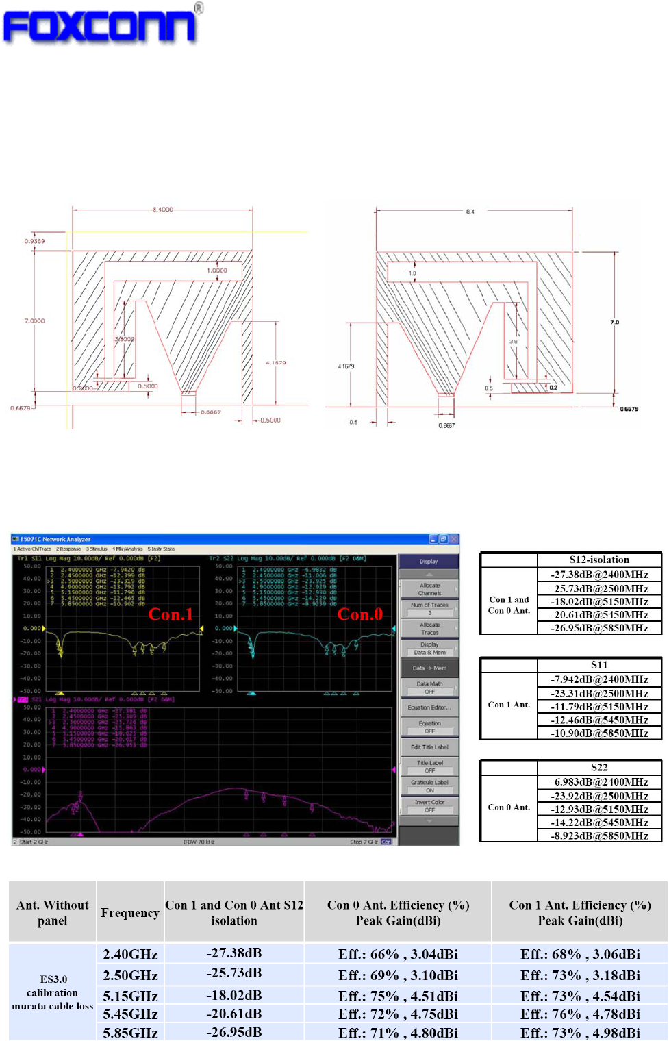
6.2 Antenna Radiation Performance
Antenna VSWR and Isolation
Antenna Peak gain and Efficiency
19
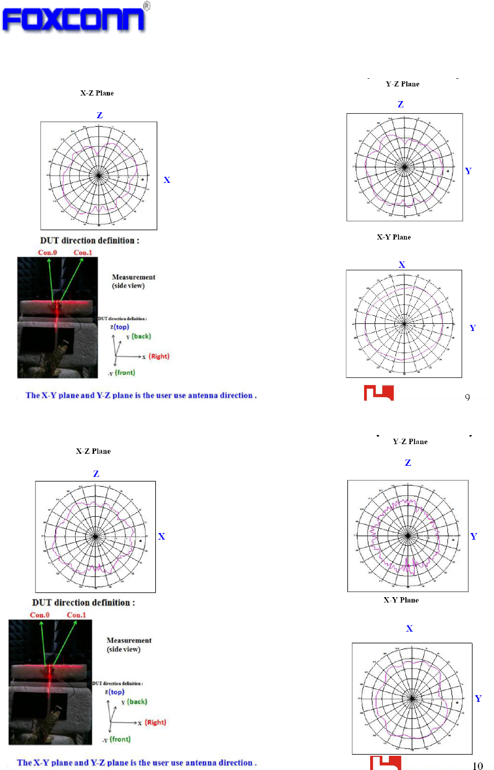
Antenna 0 2.4GHz radiation pattern
Antenna 0 5GHz radiation pattern
20
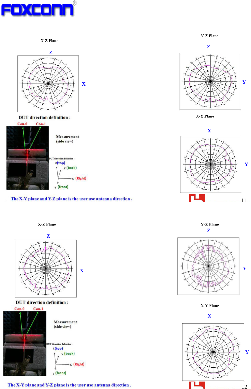
Antenna 1 2.4GHz radiation pattern
Antenna 1 5GHz radiation pattern
21
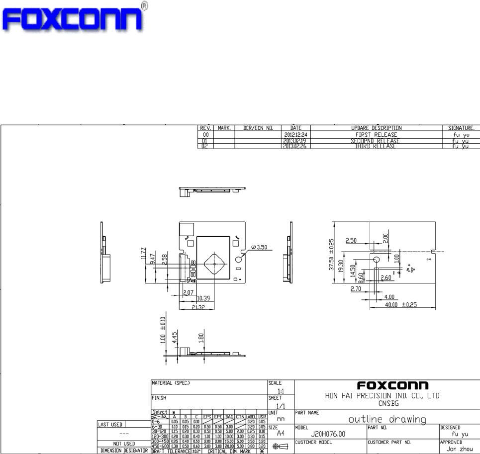
7 Module Mechanical Specifications
Dimension (W x L x H ):
40.0mmx37.5mmx5.45mm

22
8 Handling Notice
ESD
There are semiconductors on the module, please handle the module under ESD protected and
well-controlled environment (<100V).
Storage and Usage Condition
1. Moisture barrier bag must be stored under 40 ℃, humidity under 90% RH, when the moisture barrier
bag is sealed by Foxconn.
2. The calculated shelf life for the dry packed product shall be a 12 months from the bag seal date.
3. If Moisture barrier bag is open, the component must be stored in an environment of <25±5℃
/10%RH
4. Please keep the module at 30℃/70% RH.
23
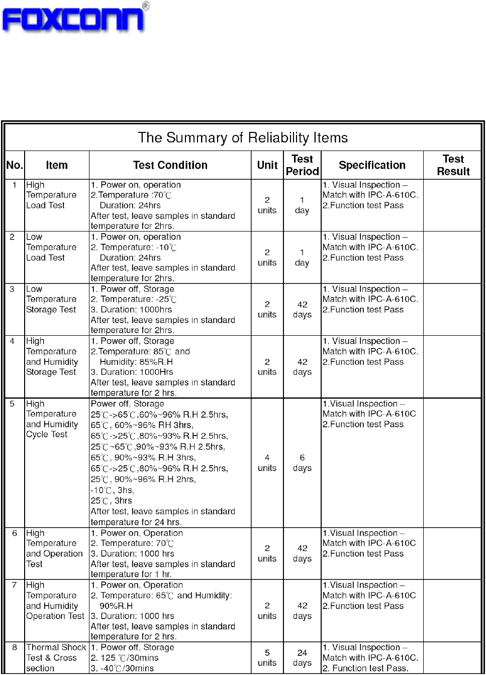
9 Reliability Test Plan
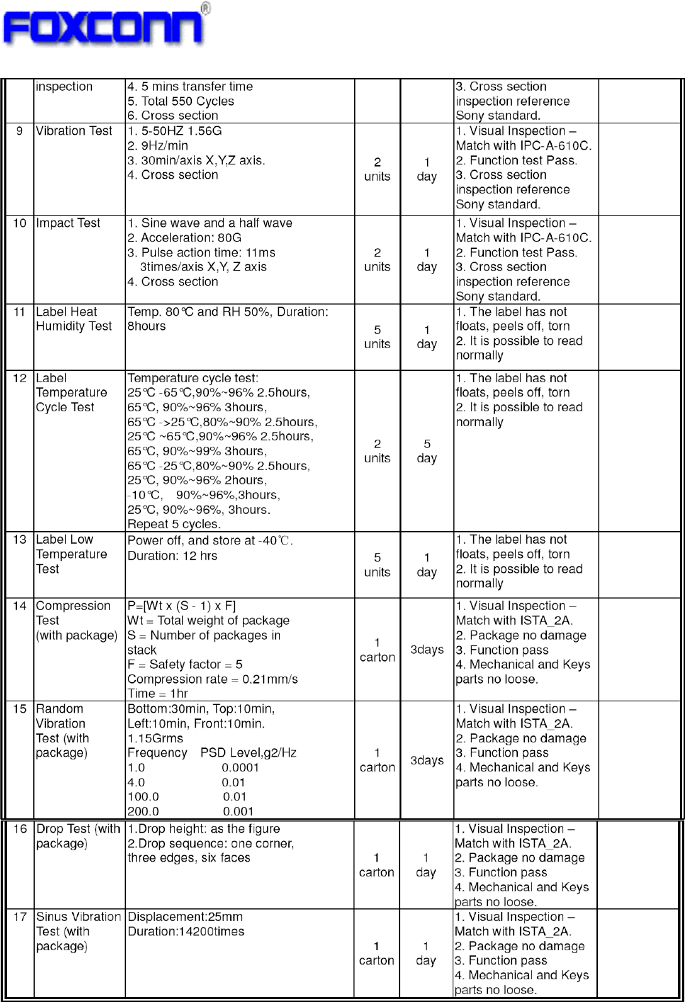
24
25
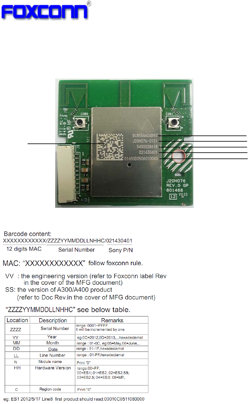
10 Marking Information
Please refer to below for the laser marking details.
1: 2D barcode, content is total 37 digits, include MAC ID, Customer data, and SONY Part Number
2: MAC address
3: Foxconn model name – Label version
4: Foxconn manufacture order
5: SONY Part Number
6: Serial number + Customer data
1
2
3
4
6
5
26
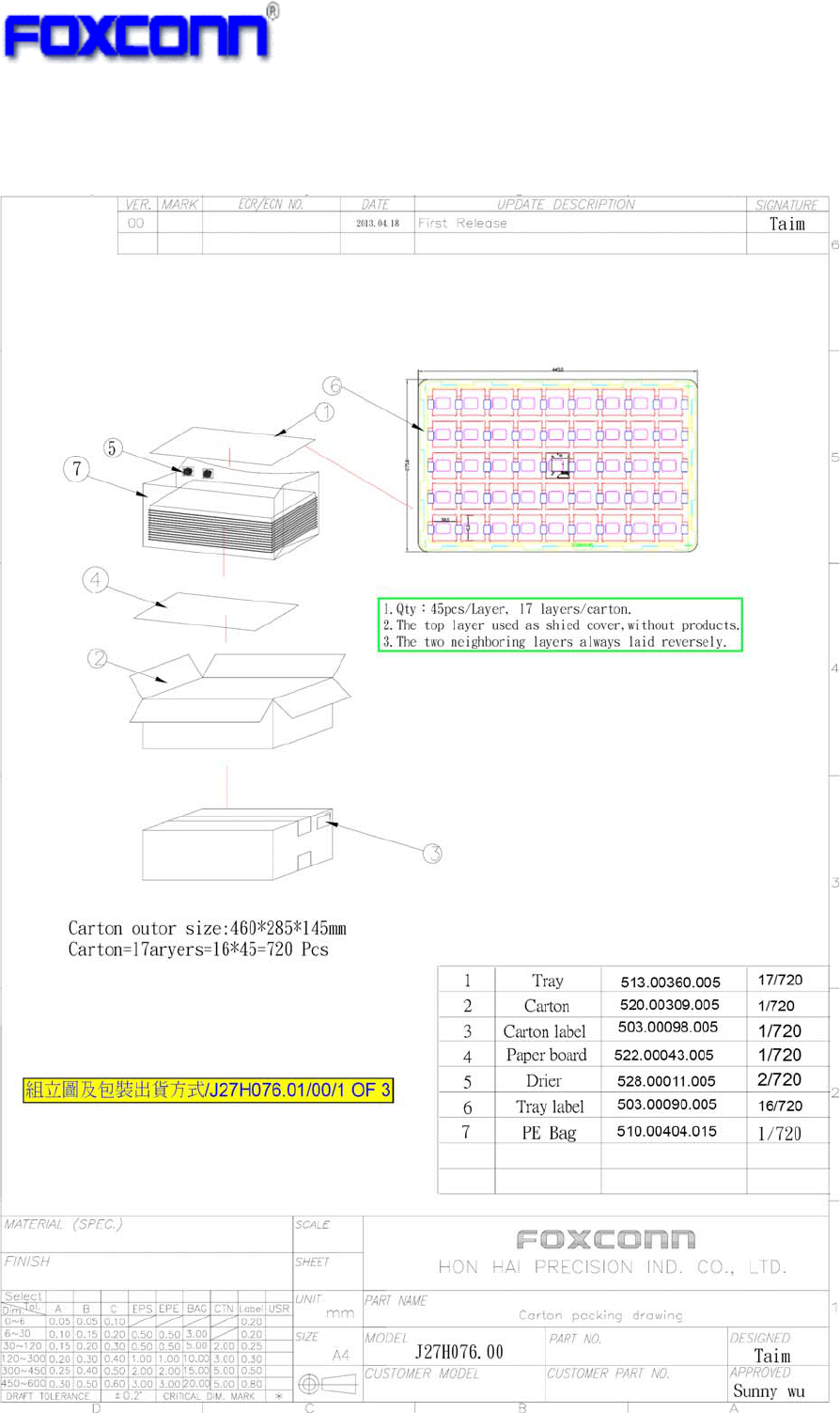
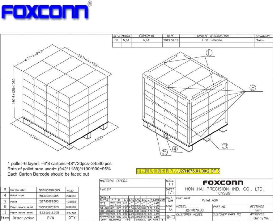
11 Packing Information
27
Federal Communication Commission Interference Statement
This device complies with Part 15 of the FCC Rules. Operation is subject to the
following two conditions: (1) This device may not cause harmful interference, and (2)
this device must accept any interference received, including interference that may
cause undesired operation.
This equipment has been tested and found to comply with the limits for a Class B
digital device, pursuant to Part 15 of the FCC Rules. These limits are designed to
provide reasonable protection against harmful interference in a residential installation.
This equipment generates, uses and can radiate radio frequency energy and, if not
installed and used in accordance with the instructions, may cause harmful interference
to radio communications. However, there is no guarantee that interference will not
occur in a particular installation. If this equipment does cause harmful interference to
radio or television reception, which can be determined by turning the equipment off
and on, the user is encouraged to try to correct the interference by one of the following
measures:
- Reorient or relocate the receiving antenna.
- Increase the separation between the equipment and receiver.
- Connect the equipment into an outlet on a circuit different from that
to which the receiver is connected.
- Consult the dealer or an experienced radio/TV technician for help.
FCC Caution: Any changes or modifications not expressly approved by the party
responsible for compliance could void the user's authority to operate this equipment.
This transmitter must not be co-located or operating in conjunction with any other
antenna or transmitter.
Operations in the 5.15-5.25GHz band are restricted to indoor usage only.
Radiation Exposure Statement:
This equipment complies with FCC radiation exposure limits set forth for an
uncontrolled environment. This equipment should be installed and operated with
minimum distance 20cm between the radiator & your body.

This device is intended only for OEM integrators under the following conditions:
1) The antenna must be installed such that 20 cm is maintained between the
antenna and users, and
2) The transmitter module may not be co-located with any other transmitter or
antenna.
As long as 2 conditions above are met, further transmitter test will not be required.
However, the OEM integrator is still responsible for testing their end-product for any
additional compliance requirements required with this module installed
IMPORTANT NOTE: In the event that these conditions can not be met (for example
certain laptop configurations or co-location with another transmitter), then the FCC
authorization is no longer considered valid and the FCC ID can not be used on the
final product. In these circumstances, the OEM integrator will be responsible for
re-evaluating the end product (including the transmitter) and obtaining a separate FCC
authorization.
End Product Labeling
This transmitter module is authorized only for use in device where the antenna may be
installed such that 20 cm may be maintained between the antenna and users. The final
end product must be labeled in a visible area with the following: “Contains FCC ID:
MCLJ20H076”. The grantee's FCC ID can be used only when all FCC compliance
requirements are met.
Manual Information To the End User
The OEM integrator has to be aware not to provide information to the end user regarding
how to install or remove this RF module in the user’s manual of the end product which
integrates this module.
The end user manual shall include all required regulatory information/warning as show in
this manual.
Industry Canada statement:
This device complies with RSS-210 of the Industry Canada Rules. Operation is subject to the following
two conditions: (1) This device may not cause harmful interference, and (2) this device must accept any
interference received, including interference that may cause undesired operation.
Ce dispositif est conforme à la norme CNR-210 d'Industrie Canada applicable aux appareils radio
exempts de licence. Son fonctionnement est sujet aux deux conditions suivantes: (1) le dispositif ne doit
pas produire de brouillage préjudiciable, et (2) ce dispositif doit accepter tout brouillage reçu, y compris
un brouillage susceptible de provoquer un fonctionnement indésirable.
Radiation Exposure Statement:
This equipment complies with IC radiation exposure limits set forth for an uncontrolled environment. This
equipment should be installed and operated with minimum distance 20cm between the radiator & your
body.
Déclaration d'exposition aux radiations:
Cet équipement est conforme aux limites d'exposition aux rayonnements IC établies pour un
environnement non contrôlé. Cet équipement doit être installé et utilisé avec un minimum de 20 cm de
distance entre la source de rayonnement et votre corps.
This device is intended only for OEM integrators under the following conditions: (For module device use)
1) The antenna must be installed such that 20 cm is maintained between the antenna and users, and
2) The transmitter module may not be co-located with any other transmitter or antenna.
As long as 2 conditions above are met, further transmitter test will not be required. However, the OEM
integrator is still responsible for testing their end-product for any additional compliance requirements
required with this module installed.
Cet appareil est conçu uniquement pour les intégrateurs OEM dans les conditions suivantes:
(Pour utilisation de dispositif module)
1) L'antenne doit être installée de telle sorte qu'une distance de 20 cm est respectée entre l'antenne et
les utilisateurs, et
2) Le module émetteur peut ne pas être coïmplanté avec un autre émetteur ou antenne.
Tant que les 2 conditions ci-dessus sont remplies, des essais supplémentaires sur l'émetteur ne seront
pas nécessaires. Toutefois, l'intégrateur OEM est toujours responsable des essais sur son produit final
pour toutes exigences de conformité supplémentaires requis pour ce module installé.
IMPORTANT NOTE:
In the event that these conditions can not be met (for example certain laptop configurations or co-location
with another transmitter), then the Canada authorization is no longer considered valid and the IC ID can
not be used on the final product. In these circumstances, the OEM integrator will be responsible for
re-evaluating the end product (including the transmitter) and obtaining a separate Canada authorization.
NOTE IMPORTANTE:
Dans le cas où ces conditions ne peuvent être satisfaites (par exemple pour certaines configurations
d'ordinateur portable ou de certaines co-localisation avec un autre émetteur), l'autorisation du Canada
n'est plus considéré comme valide et l'ID IC ne peut pas être utilisé sur le produit final. Dans ces
circonstances, l'intégrateur OEM sera chargé de réévaluer le produit final (y compris l'émetteur) et
l'obtention d'une autorisation distincte au Canada.
End Product Labeling
This transmitter module is authorized only for use in device where the antenna may be installed such that
20 cm may be maintained between the antenna and users. The final end product must be labeled in a
visible area with the following: “Contains IC: 2878D-J20H076”.
Plaque signalétique du produit final
Ce module émetteur est autorisé uniquement pour une utilisation dans un dispositif où l'antenne peut
être installée de telle sorte qu'une distance de 20cm peut être maintenue entre l'antenne et les
utilisateurs. Le produit final doit être étiqueté dans un endroit visible avec l'inscription suivante: "Contient
des IC: 2878D-J20H076".
Manual Information To the End User
The OEM integrator has to be aware not to provide information to the end user regarding how to install or
remove this RF module in the user’s manual of the end product which integrates this module.
The end user manual shall include all required regulatory information/warning as show in this manual.
Manuel d'information à l'utilisateur final
L'intégrateur OEM doit être conscient de ne pas fournir des informations à l'utilisateur final quant à la
façon d'installer ou de supprimer ce module RF dans le manuel de l'utilisateur du produit final qui intègre
ce module.
Le manuel de l'utilisateur final doit inclure toutes les informations réglementaires requises et
avertissements comme indiqué dans ce manuel.
Caution :
(i) the device for operation in the band 5150-5250 MHz is only for indoor use to reduce the potential for
harmful interference to co-channel mobile satellite systems;
(ii) the maximum antenna gain permitted for devices in the bands 5250-5350 MHz and 5470-5725 MHz
shall comply with the e.i.r.p. limit; and
(iii) the maximum antenna gain permitted for devices in the band 5725-5825 MHz shall comply with the
e.i.r.p. limits specified for point-to-point and non point-to-point operation as appropriate.
(iv) Users should also be advised that high-power radars are allocated as primary users (i.e. priority
users) of the bands 5250-5350 MHz and 5650-5850 MHz and that these radars could cause interference
and/or damage to LE-LAN devices.
Avertissement:
Le guide d’utilisation des dispositifs pour réseaux locaux doit inclure des instructions précises sur les
restrictions susmentionnées, notamment :
(i) les dispositifs fonctionnant dans la bande 5 150-5 250 MHz sont réservés uniquement pour une
utilisation à l’intérieur afin de réduire les risques de brouillage préjudiciable aux systèmes de satellites
mobiles utilisant les mêmes canaux;
(ii) le gain maximal d’antenne permis pour les dispositifs utilisant les bandes 5 250-5 350 MHz et 5 470-5
725 MHz doit se conformer à la limite de p.i.r.e.;
(iii) le gain maximal d’antenne permis (pour les dispositifs utilisant la bande 5 725-5 825 MHz) doit se
conformer à la limite de p.i.r.e. spécifiée pour l’exploitation point à point et non point à point, selon le cas.
(iv) De plus, les utilisateurs devraient aussi être avisés que les utilisateurs de radars de haute puissance

sont désignés utilisateurs principaux (c.-à-d., qu’ils ont la priorité) pour les bandes 5 250-5 350 MHz et 5
650-5 850 MHz et que ces radars pourraient causer du brouillage et/ou des dommages aux dispositifs
LAN-EL.
For Taiwan:低功率電波輻射性電機管理辦法
第十二條 經型式認證合格之低功率射頻電機,非經許可,公司、商號或使用者均不得擅自變更頻率、加大
功率或變更原設計之特性及功能。
第十四條 低功率射頻電機之使用不得影響飛航安全及干擾合法通信;經發現有干擾現象時,應立即停用,
並改善至無干擾時方得繼續使用。
前項合法通信,指依電信法規定作業之無線電通信。
低功率射頻電機須忍受合法通信或工業、科學及醫療用電波輻射性電機設備之干擾。
在5.25-5.35 秭赫頻帶內操作之無線資訊傳輸設備,限於室內使用。
1. 本模組於取得認證後將依規定於模組本體標示審驗合格標籤。
2. 系統廠商應於平台上標示「本產品內含射頻模組: XXXyyyLPDzzzz-x」字樣。