HON HAI PRECISION IND T60M665 Bluetooth Wireless Card in Notebook PC User Manual Cover
HON HAI Precision Ind. Co., Ltd. Bluetooth Wireless Card in Notebook PC Cover
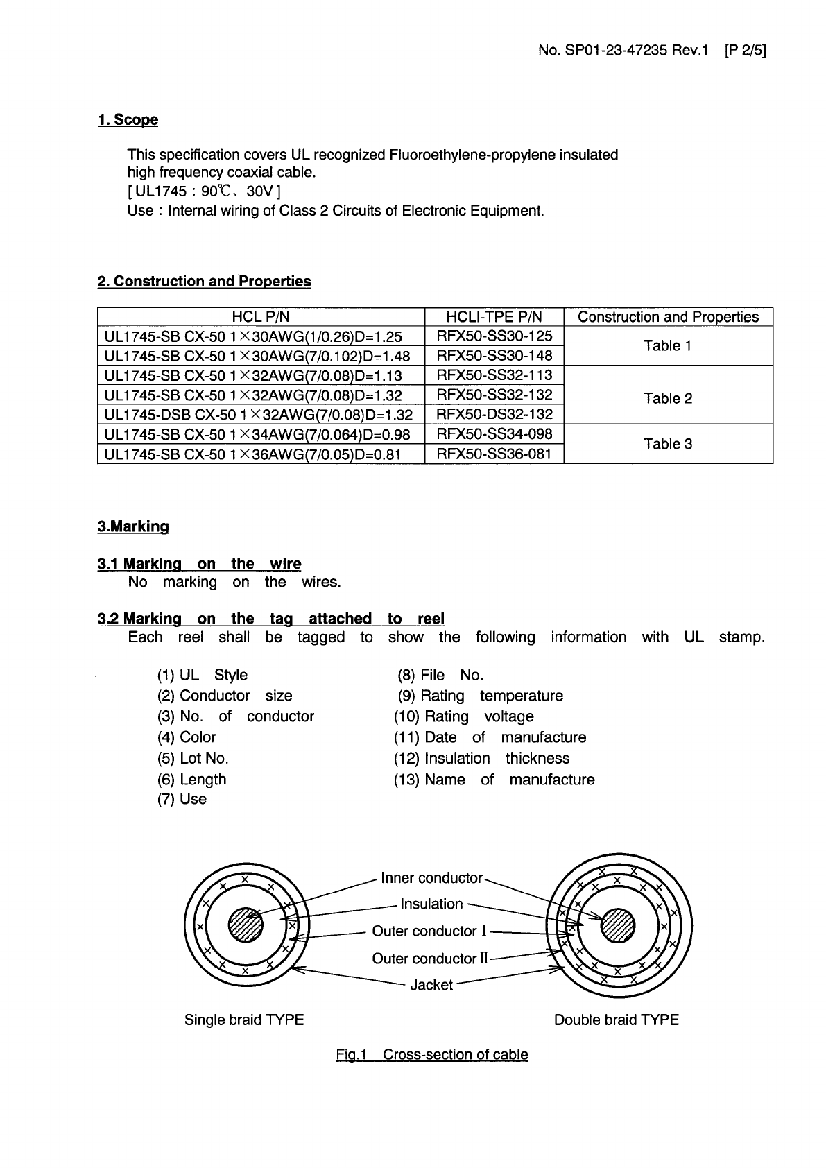
Contents
- 1. users manual
- 2. Antenna Specification
Antenna Specification
承認書
APPROVAL SHEET
客戶名稱
Customer :
客戶料號
Customer P/N : 25.90143.001
適用機種
Model No. : GANNET
送件日期
Submitted Date:
承認日期
Approved Date :
瀚宇料號
HannStar P/N :
品 名
Description :
APPROVED 承認編號
承認人簽章
瀚宇電子股份有限公司
HannStar Electronics Corp.
台北縣 242 新莊市化成路 211 巷5號
No. 5, Lane 211, Hua Cheng Rd., Hsin Chuang Taipei
Hsien, Taiwan, R.O.C.
Tel: 886-2-22779377 Fax: 886-2-2994-4240
http://www.elc.hannstar.com.tw
Wistron Corporation
September. 05,
200
3
W
A00
101
BLUETOOTH for GANNET system

Prepared: Leo Chong Checked: Angel Lee Approved: Allen Lin Date: May/13’ 03
瀚宇電子股份有限公司
HannStar Electronics Corp.
承認書索引
Index
Customer P/N: 25.90143.001
Model: GANNET
HSE P/N: WA00101
1. Introduction
2. Revision History
3. Product Spec.
4. Environment Performance Test
5. Package
6. FAI Test
7. VSWR CPK
8. Cable Spec.
9. Connector Spec.
10. PCB
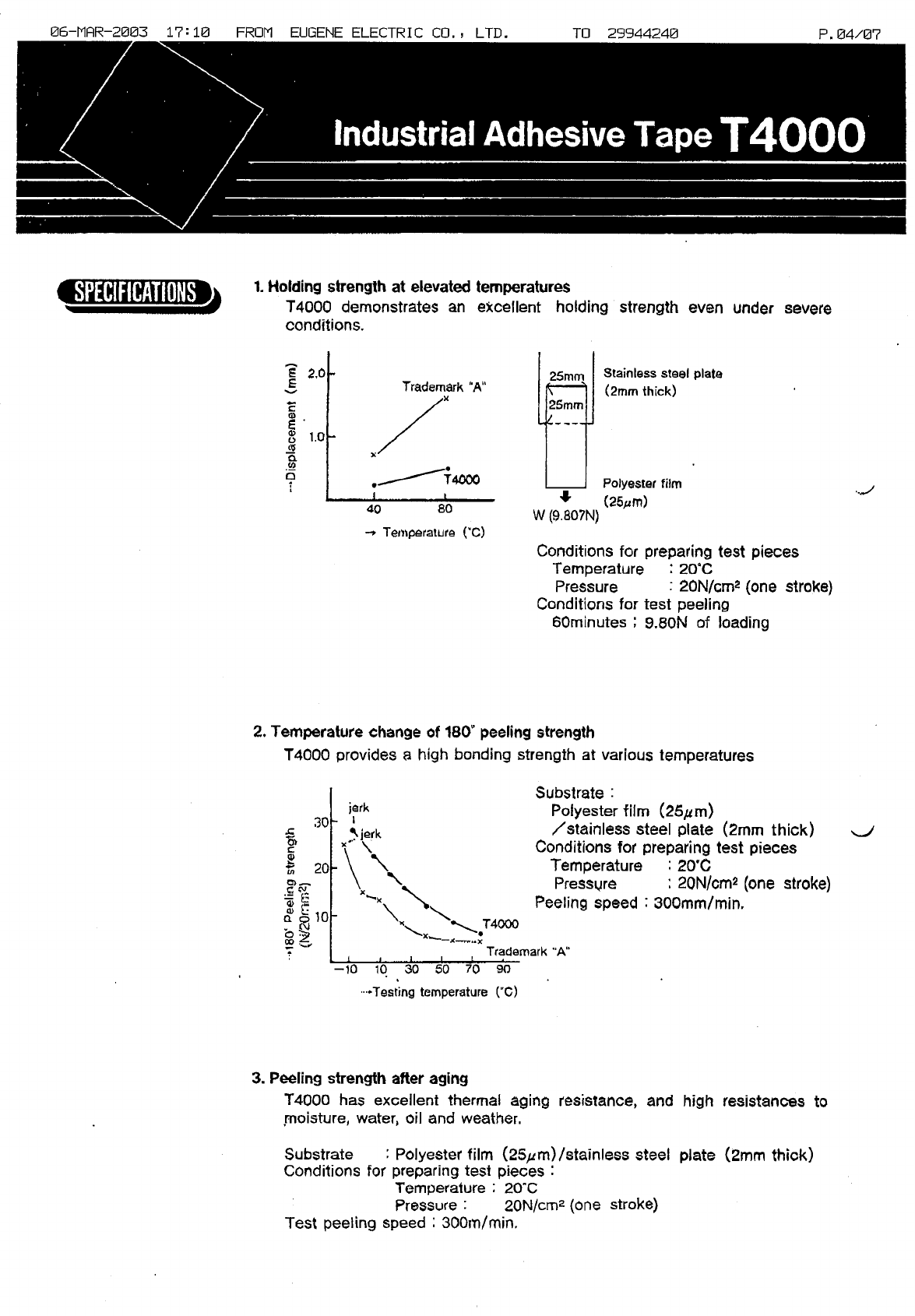
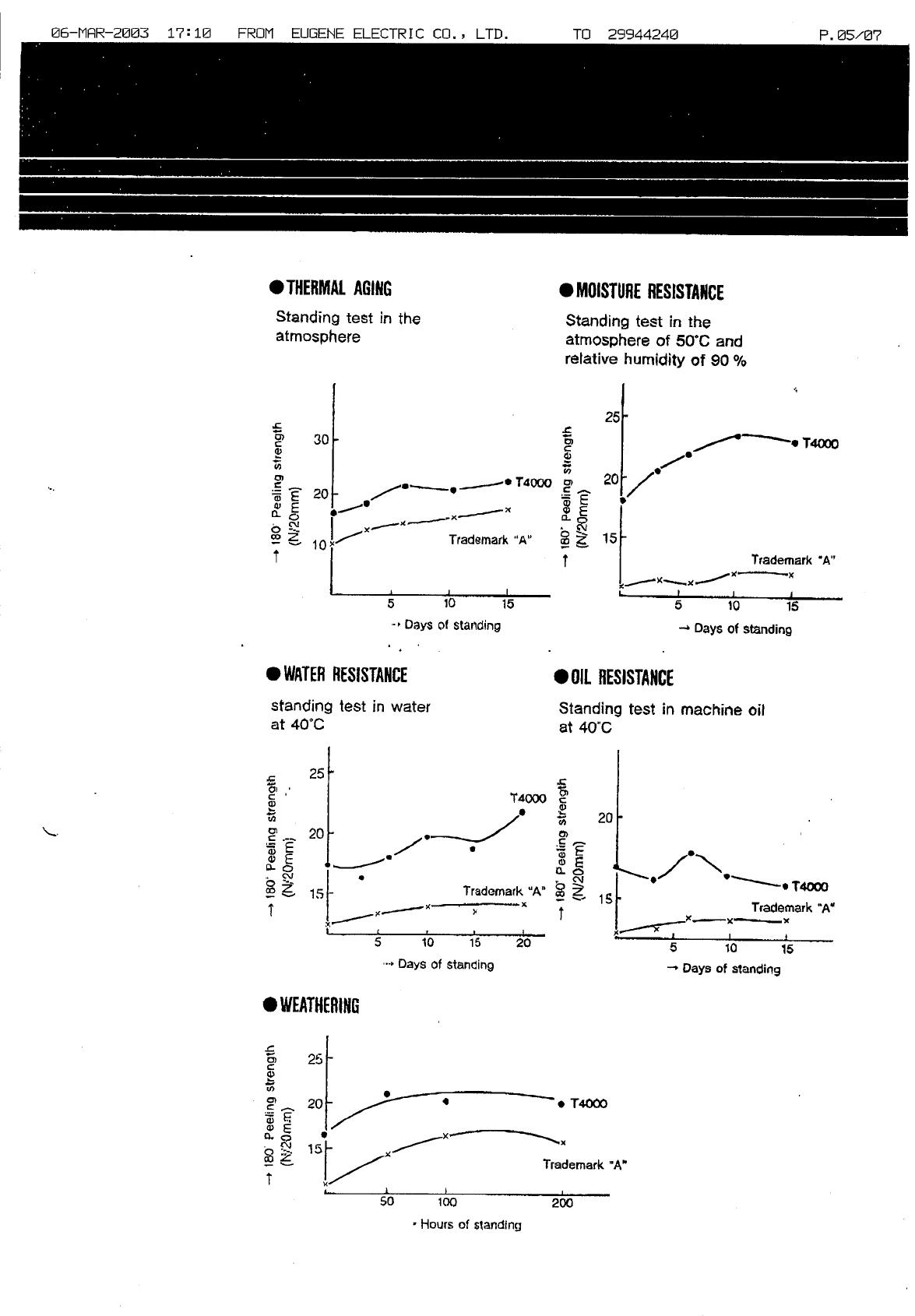
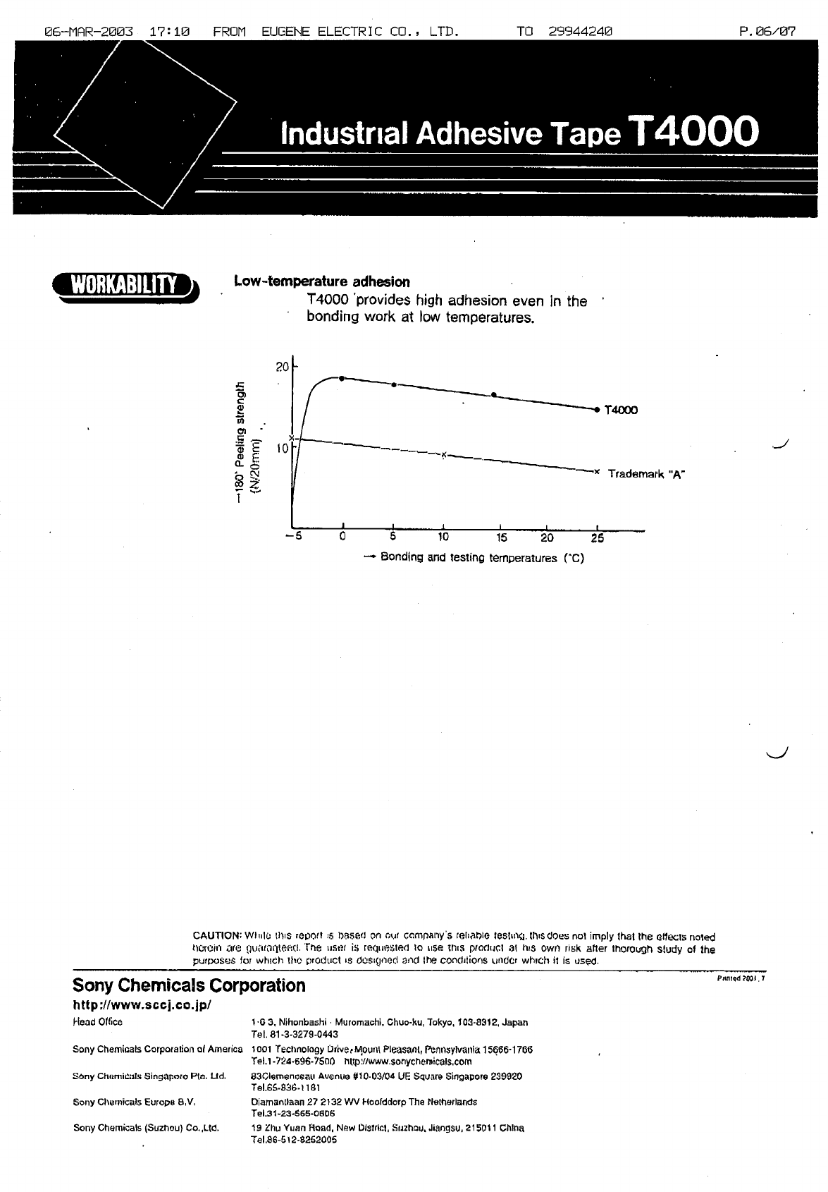
11. SONY T4000
HannStar Electronics Corp.
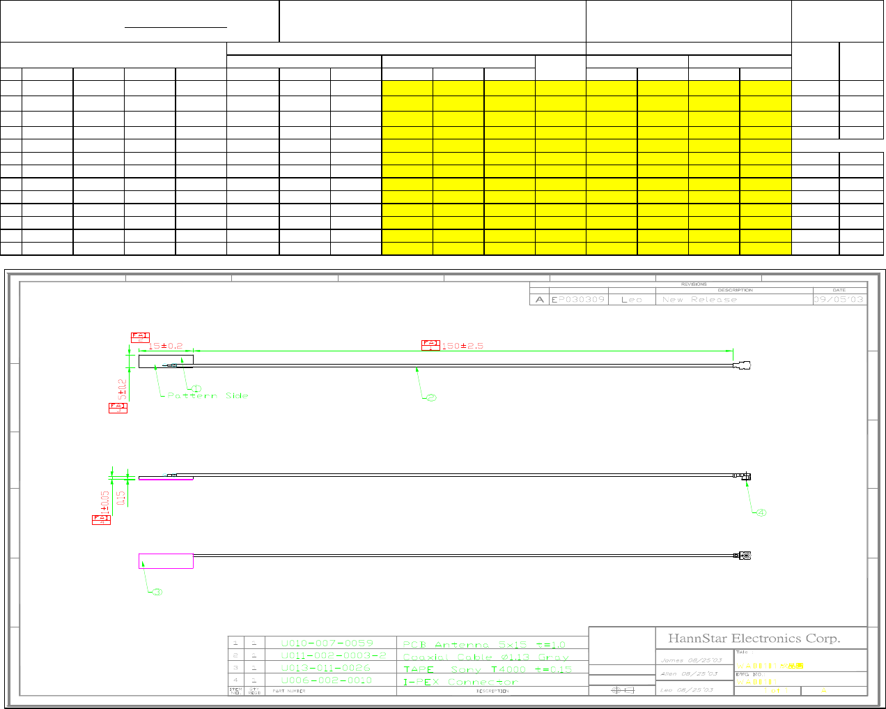
1. Introduction
Antennas for Bluetooth system
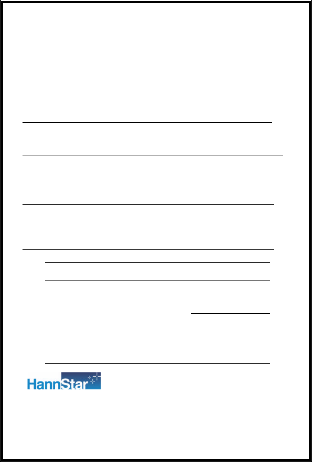
Bluetooth Antenna (PCB type)
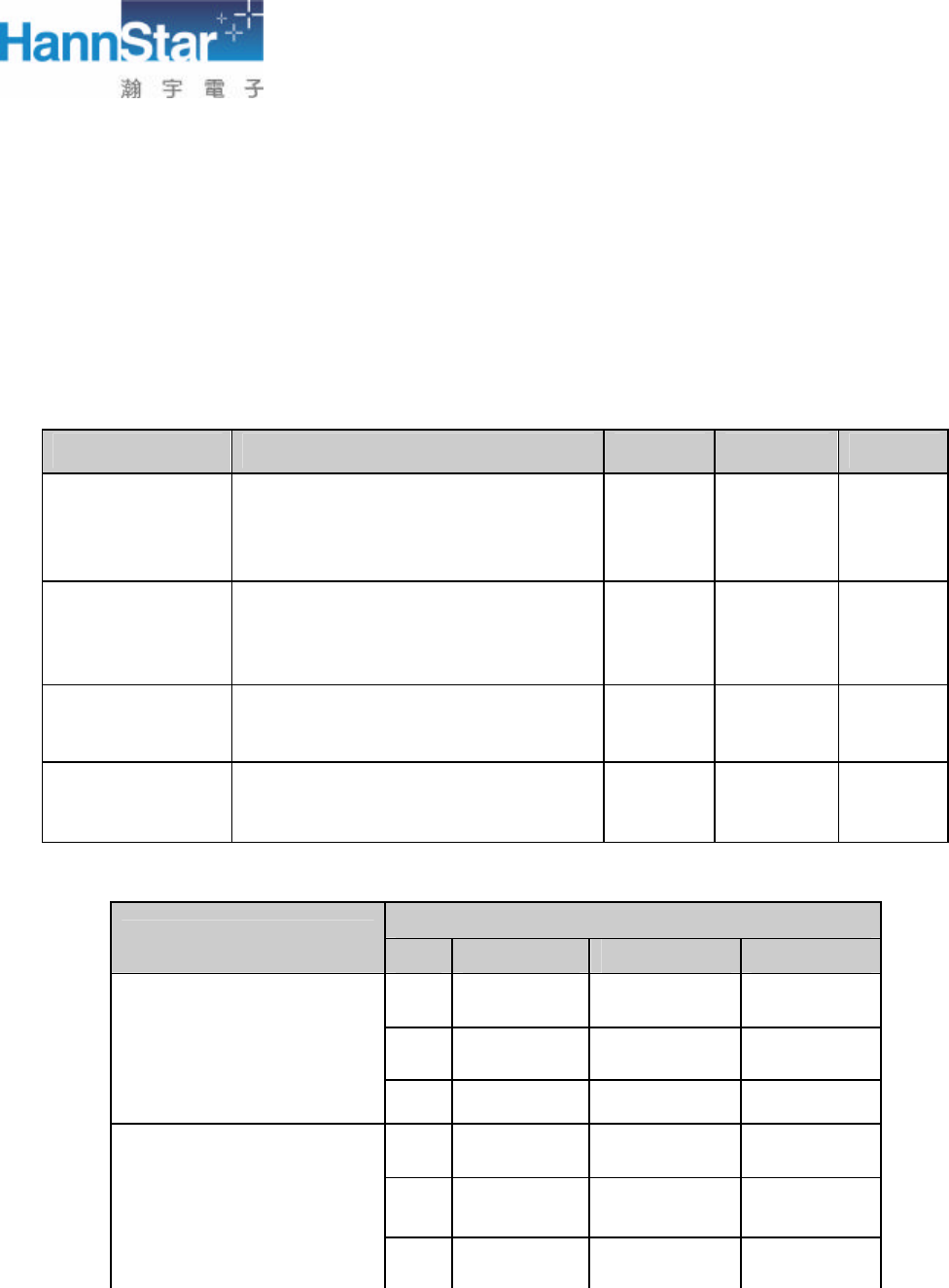
1. Application: Left side in motherboard location
2. Cable length: 150mm, White
(IPEX connector with φ1.13mm RF cable)
2. Revision History
Date Version Change Description
09/05/2003 A New Release
3. Product Spec.
3.1 Antenna Design Specification
Measure environment LCD angle 110 degree
3.1.1 VSWR
2G4 ISM (2.40GHz-2.483GHz)
VSWR 2.40GHz
2.45GHz
2.50GHz
Bluetooth antenna ≦2
3.1.2 Average gain
2G4 ISM (2.40GHz-2.483GHz)
Average Gain 2.40GHz
2.45GHz
2.50GHz
Bluetooth Antenna ≧-5
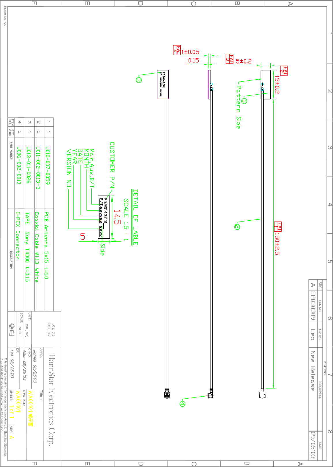
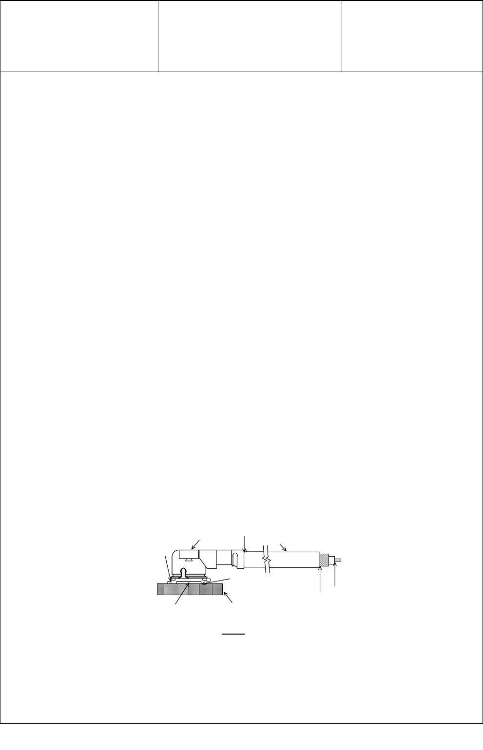
3.2 Mechanical Spec.
See the attached drawing
Bluetooth Antenna
HannStar Electronics Corp.
3.3 Antenna BOM structure
3.4 Antenna Test Results
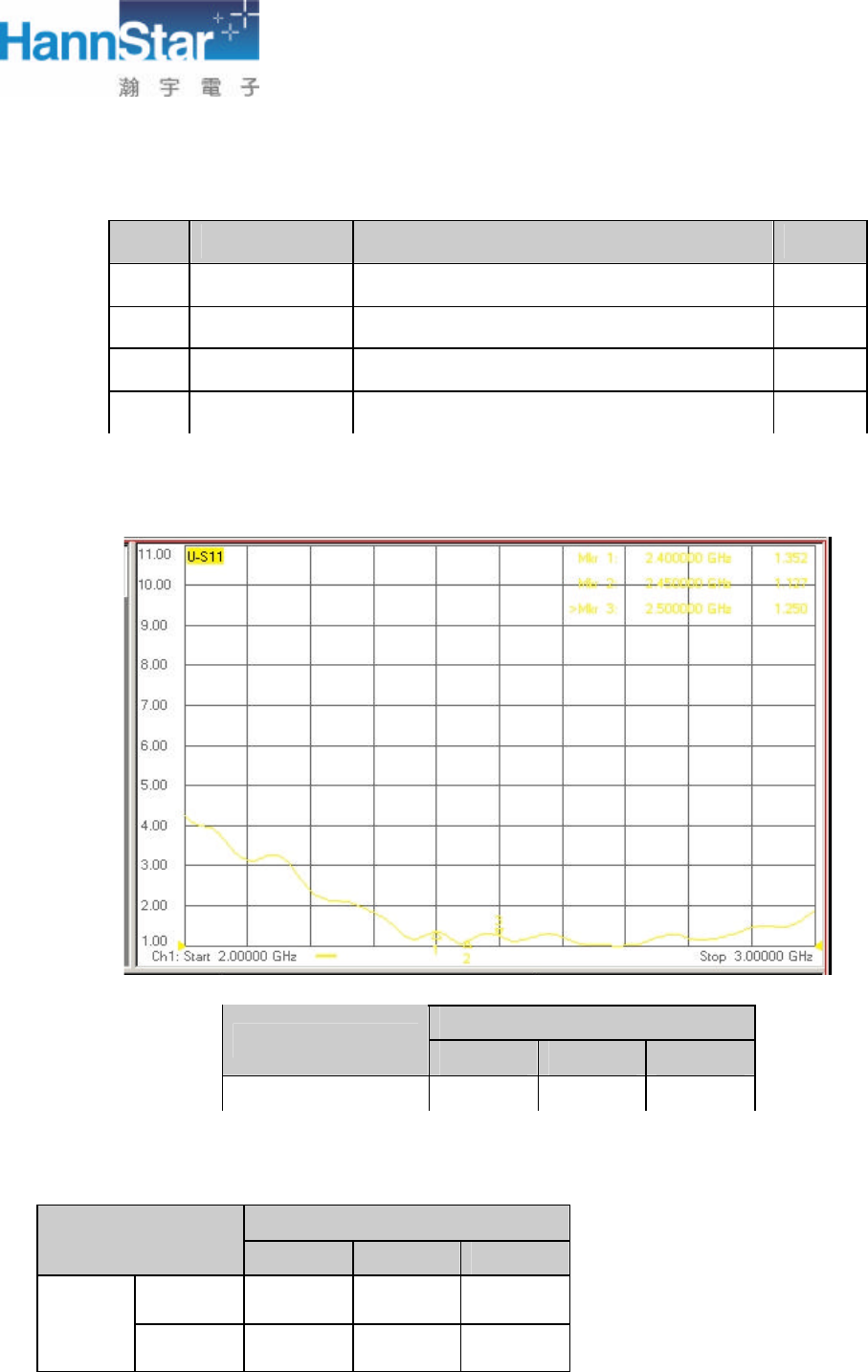
3.4.1 VSWR
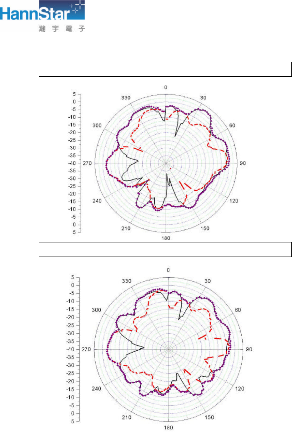
3.4.2 Radiation Pattern
2G4 ISM (2.40GHz-2.483GHz)
Gain(dBi) 2.40GHz
2.45GHz
2.50GHz
Peak 1.23 -0.49 0.15
Bluetooth
Antenna Average
-4.08 -4.19 -4.47
NO. Part NO. Description Q’ty
1 U011-002-0013-2
Hitachi Cable O1.13 White 150mm 1
2 U010-007-0059 PCB 5x15mm 1
3 U006-002-0010 I-PEX Connector 1
4 U013-011-0026 Type SONY T4000 1
2G4 ISM (2.40GHz-2.483GHz)
VSWR 2.40GHz
2.45GHz
2.50GHz
Bluetooth Antenna 1.1218 1.1227 1.1244
HannStar Electronics Corp.
Bluetooth Antenna @- 2.40 GHz
Bluetooth Antenna @- 2.45 GHz
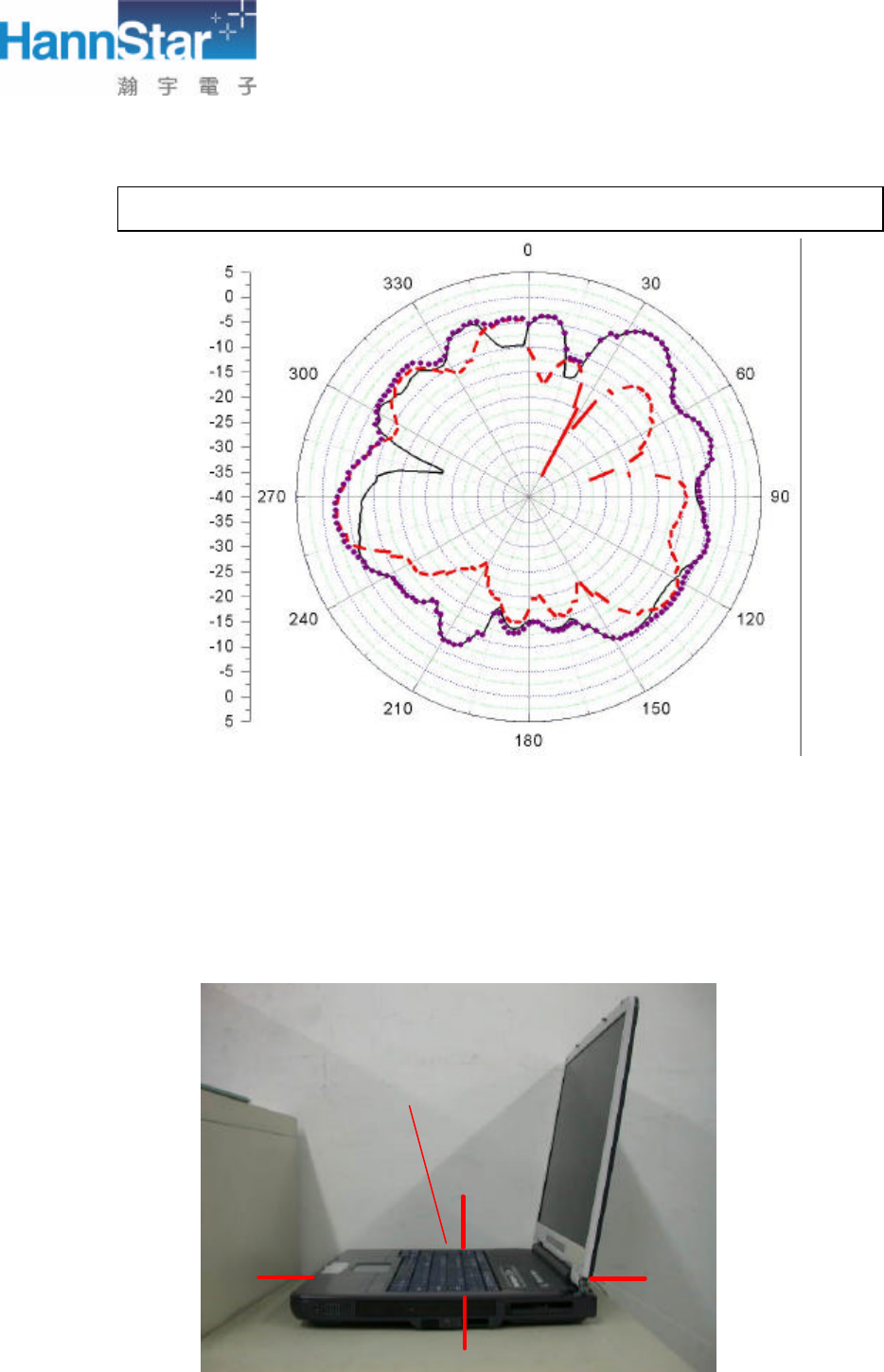
HannStar Electronics Corp.
Bluetooth Antenna @- 2.483 GHz
0°
90°
180°
Bluetooth Antenna
HannStar Electronics Corp.
4. Environment Performance Test
4.1 Introduction
This EQT (Environment Qualification Test) report is used to describe the final status of PCB type
Antenna about the EQT test results.
4.2 Test Items and Results
4.2.1 the following table is used to show the final status of PCB type Antenna.
Test Item Specification Test Result
Tested By Remark
Thermal Shock
Temperature range:-20℃~80℃
Hold Time:30 min
Total cycle:20 cycles
Pass HSE
Vibration
(Need NB)
Frequency 5 to 500Hz
Overall rms level : 0.6G P-P~2.0G P-P
Duration of test : 1 Hr/cycle
Number of axes : X,Y,Z 1 cycle/axis
Pass HSE
Salt Spray Chamber temperature : 35℃
Salt : 5%
Hold time : 48 Hr Pass HSE
Contact Engagement
& Separation Forces
Speed : 22 mm/mint
Inspection Item : Soldering Pull strength
Soldering pull strength > 1 kgw
Pass HSE
2G4 ISM (2.40GHz-2.483GHz)
VSWR S/N
2.40GHz 2.45GHz 2.50GHz
01 1.1218 1.1227 1.1244
02 1.1352 1.1312 1.1364
Before Thermal Shock Test
03 1.3122 1.1532 1.2123
01 1.5623 1.4313 1.6325
02 1.5325 1.3256 1.5421
After Thermal Shock Test
03 1.4562 1.4121 1.5213
270°
HannStar Electronics Corp.
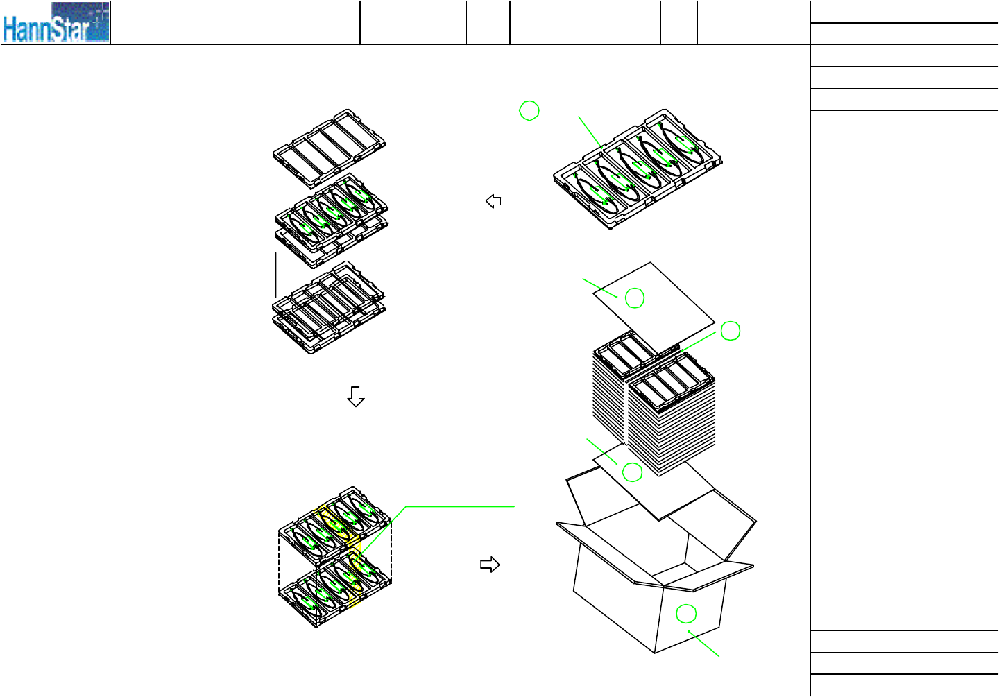
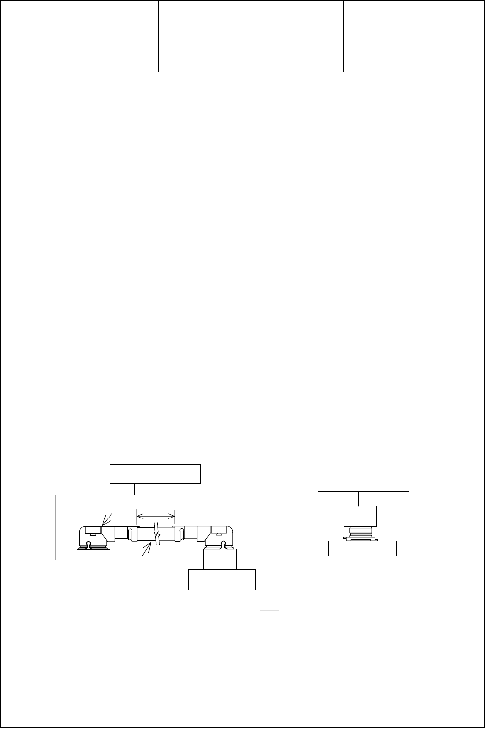
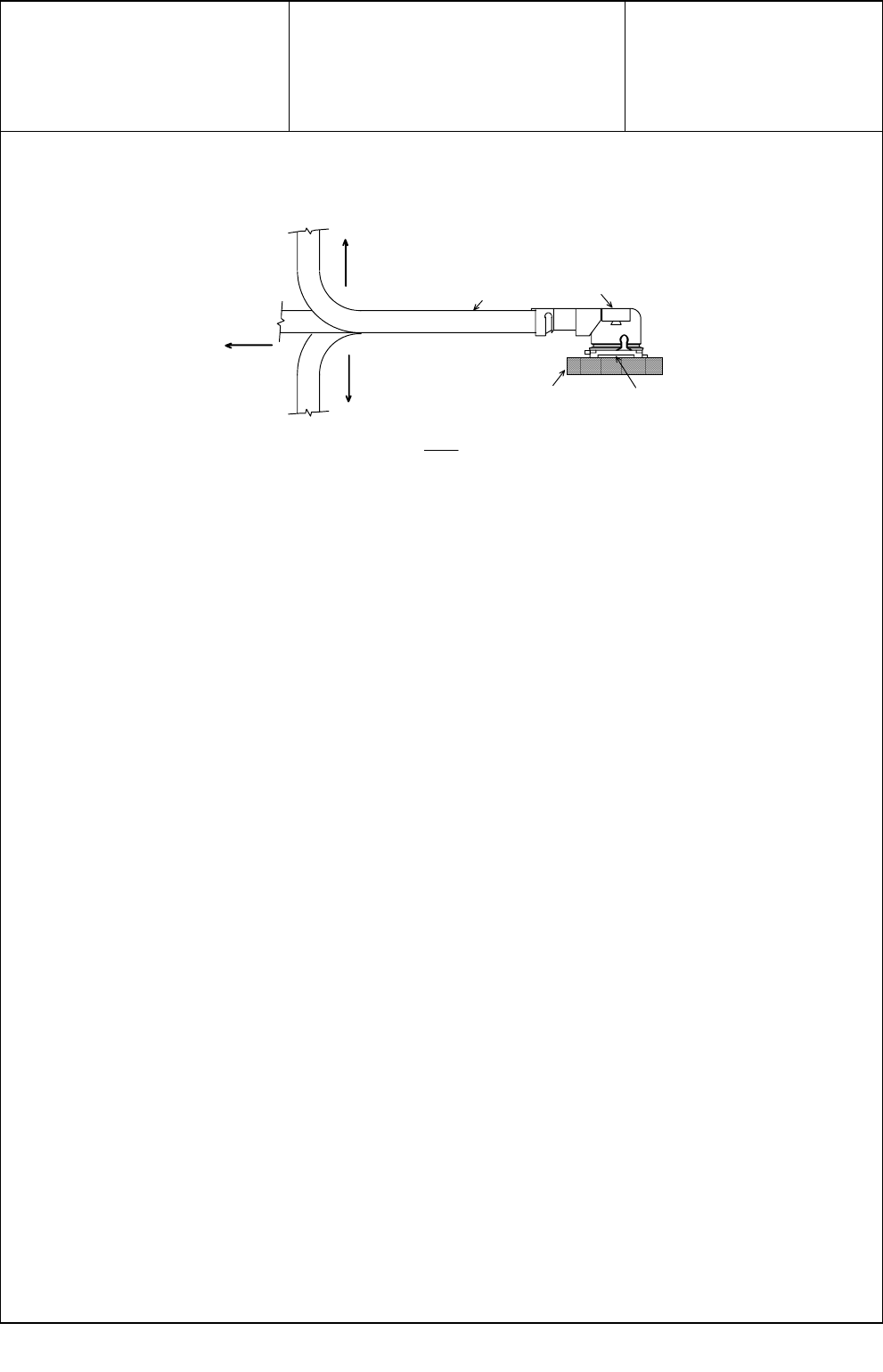
5. Package
See the attached drawing.
Bluetooth Antenna
2G4 ISM (2.40GHz-2.483GHz)
VSWR
S/N
2.40GHz
2.45GHz
2.50GHz
01 1.21 1.23 1.22
02 1.25 1.26 1.28 Before Vibration Test
03 1.13 1.11 1.16
01 1.46 1.35 1.50
02 1.48 1.45 1.55
After Vibration Test
03 1.54 1.50 1.61
Bluetooth Antenna (Right)
2G4 ISM (2.40GHz-2.483GHz)
VSWR
S/N
2.40GHz
2.45GHz
2.50GHz
01 1.25 1.23 1.26
02 1.16 1.12 1.13 Before Salt Spray Test
03 1.19 1.17 1.18
01 1.50 1.44 1.48
02 1.45 1.46 1.42
After Salt Spray Test
03 1.50 1.49 1.53
Main Antenna (Right)
Number 1 2 3 Max Min Avg
Soldering Pull strength
(Unit:kg) 3.985 3.957 3.967 3.985 3.957 3.696
適用客戶類別
二.紙箱包裝方式:
一.成品包裝方式:
包裝作業說明:
包裝作業標準 適用
產品
核 定:
制 定:
覆 核:
編 號:
包裝
類別 Tray 盤
版 次:
修訂日期:
頁 次:
制定日期:
備註: 01
00
紙箱
1
Wireless Lan
蔡麗文
圖 一
Tray盤
4
20個TRAY盤
上蓋
圖 二
用膠帶纏繞一圈
裝入紙箱
注意事項:
1.包裝前請確認成品無夾帶
綿絮或污染物.
2.包裝時不得有毀損以及污
染成品之情形發生.
3.包裝時必須注意成品與包
材之方向性,不得有方向
錯誤之情形發生.
4.TRAY是否有變形
破裂情況發生.
5.TRAY和TRAY結合是否有
過緊或鬆脫情況發生.
隔板
2
國內一般客戶 90.07.10
P899-T007
隔板
每個TRAY盤共裝15PCS
成品,每小格放3PCS,
方向如圖(一)所示.
每疊20個TRAY盤,最上
層用一個空TRAY做上蓋
再用膠帶將TRAY
纏繞一圈,以防
圖(三)所示.
片隔板.蓋上箱子用膠帶封
面貼上標籤紙一張
箱部分,出貨
物填滿.
如圖
盤小邊
脫落,如
裝箱前,先放一片隔板在
圖 三
時須以
每疊成品300PCS,
中間
須以隔板分開,如圖示(四)
所示,完成後封箱前再放一
緩衝
旋轉堆疊
圖 四
隔板
(二)所示.
箱底,放入成品二疊
合,在側
如有零
3
2
25.90117.001
HSE
Date:
Yuhina Antenna Leo Manufacturing Site:HSE
Gauge#/Unit:
游標卡尺 (mm)
AAllen Lin
Gauge/Unit:
尺(mm)
Inspection Precision
ITEM
LOCATION
NOMINAL
+TOL
-TOL
1
2
3
1
2
3
Mean
UPPER
LOWER
HIGH
LOW
Method of Gauge
1150.0 2.5 2.5 151.0 150.0 149.0 -0.05 0.05 0150.00 40% 40% 尺1mm
215.0 0.2 0.2 15.1 14.9 15.100 -0.1 0-0.02 15.03 50% 50% 游標卡尺 0.01mm
35.0 0.2 0.2 5.12 5.11 4.99 -1 1 1 5.07 60% 5% 游標卡尺 0.01mm
4
1.0
0.05
0.05
0.97
0.98
0.98
0.01
-0.02
-0.05
1.0
0%
60%
游標卡尺
0.01mm
Drawing
DRAWING SPECIFICATIONS
INSPECTION RESULTS
INSPECTION ANALYSIS
Sample Number Deviation from Nominal % Tolerance Acc/Rej
Production Line:
FAI DATA SHEET
Drawing Number: Supplier :
2003/5/16
Revision: Approved by:
Part Description: Inspected by:
ECN NO. ECN BY.
REV.
876
A
B
541 2 3
A
C
D
F
.X ±
APPD:
DR:
NONE
CHKD:UNIT:
SCALE:
mm (inch)
.XX ±
REV:SHEET:
This drawing contains information that is proprietary to HannStar Electronics
Corp. And should not be used without written permisson.
E
C
D
F
ED001-980729
E
B
0.3
0.2
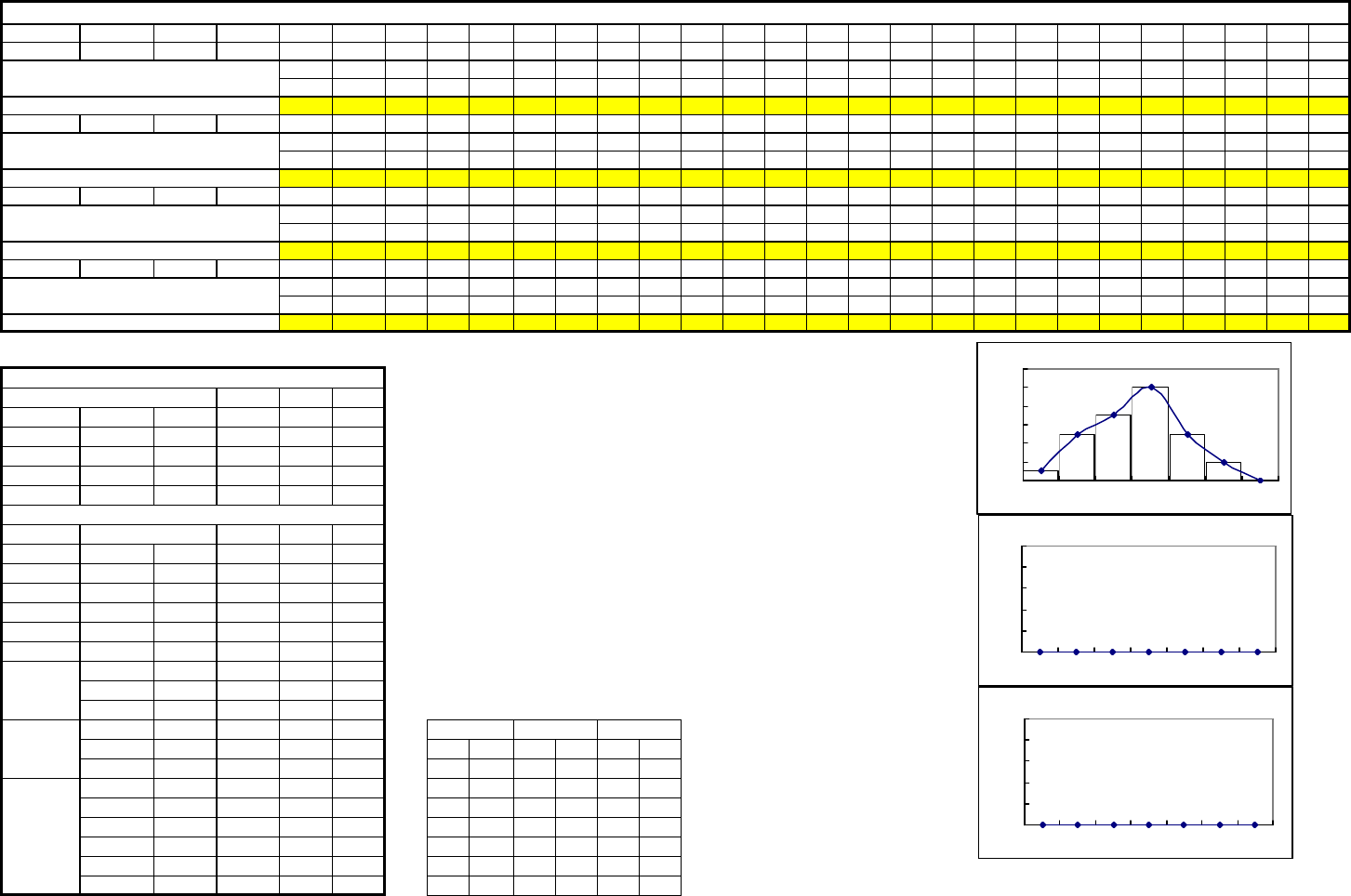
7. VSWR CPK Cpk of Antenna
Part Number:25.90019.001
Measurement Value
Item Spec. Torance + Torance - 1 2 3 4 5 6 7 8 9 10 11 12 13 14 15 16 17 18 19 20 21 22 23 24 25
VSWR (b) 2.00 0 0 1.32 1.42 1.36 1.52 1.42 1.48 1.36 1.54 1.63 1.57 1.36 1.29 1.38 1.54 1.27 1.43 1.55 1.38 1.37 1.25 1.31 1.45 1.46 1.43 1.45
26 27 28 29 30 31 32 33 34 35
1.49 1.39 1.33 1.48 1.47
組界 51.25 1.33 1.40 1.48 1.55 1.63 1.71
26 27 28 29 30 31 32 33 34 35
組界
26 27 28 29 30 31 32 33 34 35
組界
組界
Engineering Specification
工程尺寸
VSWR (b)
工程規格 Product spec 1.5000 1.7500 VSWR (b )
正公差 Tolerence 0.5000 0.7500
負公差 Tolerence 0.5000 0.7500
工程上限 USL 22.5
工程下限 LSL 1 1
Actual Data
量測尺寸
VSWR (b)
平均數 X bar 1.4233
標準差 Sigma 0.0940
中間值 Median 1.4250 VSWR (a)
眾數 Mode 1.3600
最大值 Max 1.6300
最小值 Min 1.2500
1 Sigma 1.5173
UCL 2 Sigma 1.6113
3個標準差 3 Sigma 1.7052
1 Sigma 1.3294
LCL 2 Sigma 1.2354 組別 次數 組別 次數 組別 次數 Remark:
3個標準差 3 Sigma 1.1414 1.29 1###### 0 ##### 0 Gauge: Dimension C
雙邊CP 1.77 1.36 5###### 0 ##### 0
單邊CPL 1.50 1.44 7###### 0 ##### 0
單邊CPU 2.05 1.52 10 ###### 0 ##### 0
製程能力 單邊CP 1.50 1.59 5###### 0 ##### 0
Ca 0.00 1.67 2###### 0 ##### 0
Cpk 1.77 1.74 0###### 0 ##### 0
VSWR B C
0
2
4
6
8
10
12
1.29 1.36 1.44 1.52 1.59 1.67 1.74
0
0
0
1
1
1
0.00 0.00 0.00 0.00 0.00 0.00 0.00
0
0
0
1
1
1
0.00 0.00 0.00 0.00 0.00 0.00 0.00
第 1 頁

z Cable – Hitachi

z I-PEX Connector
I-PEX CO.,LTD sheet 1 of 9
PRODUCT SPECIFICATION
製 品 規 格
No. PRS-1180
MHF series micro coaxial connector
(at 6GHz)
Qualification Test Report No. TR-1037
2 S2031 K.O May/17/’02 K.K Prepared by Reviewed by Approved by
1 S1063 K.O Dec/25/’01 K.K
0 S1055 K.O Nov/16/’01
REV. ECN BY DATE APP.
REVISION RECORD
K.Ohbayashi
Nov/16/’01
E.Kawabe
Nov/20/’01
K.Katabuchi
Nov/21/’01
Form Rev. 0
I-PEX CO.,LTD sheet 2 of 9
DOCUMENT CLASSIFICATION TITLE No.
Product Specification MHF series micro coaxial PRS-1180
製品規格 connector
1. Scope / 序言
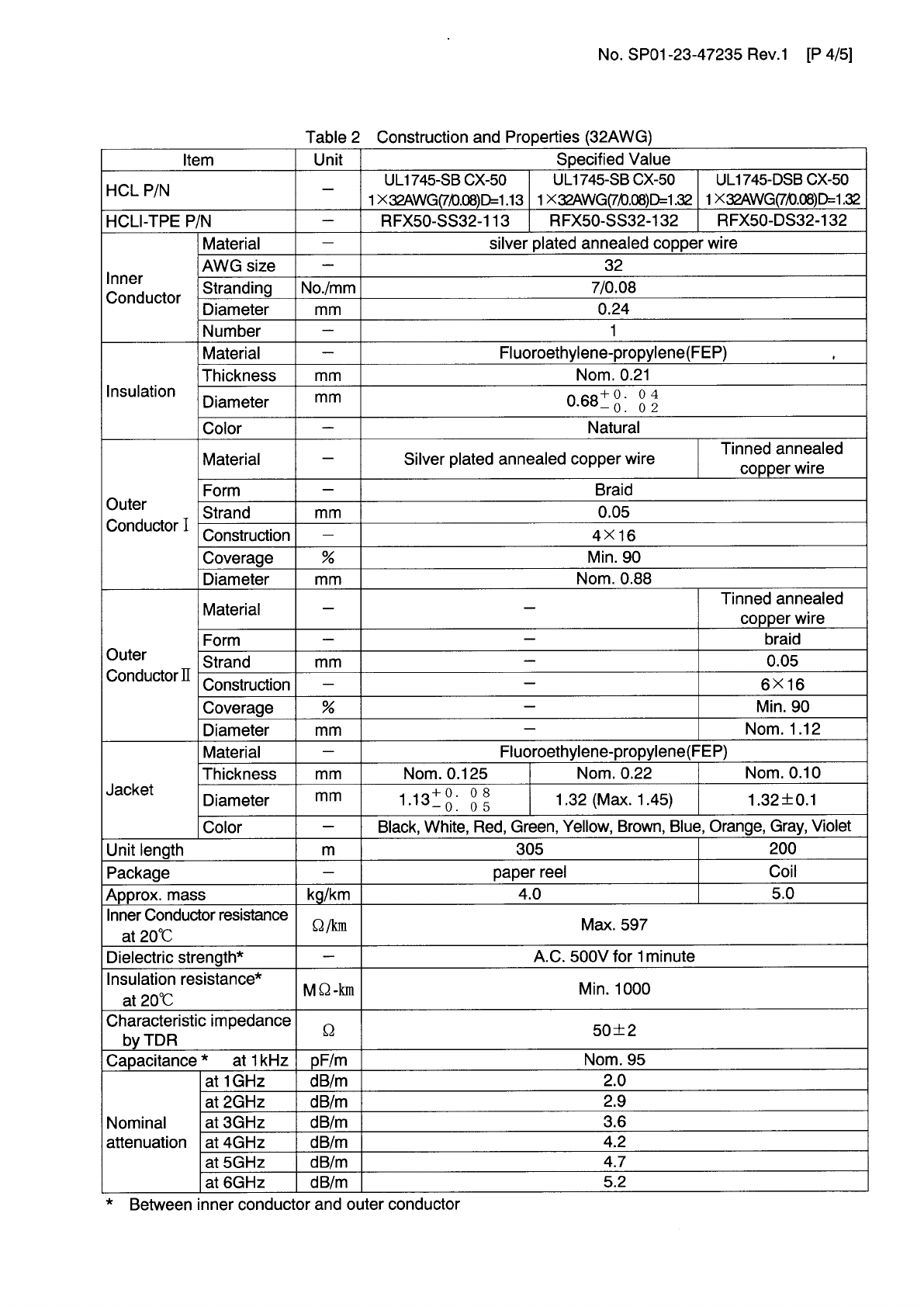
MHF series micro coaxial connector is a wire to board connector for AWG#32 coaxial cable .
MHF series micro coaxial connector は、AWG#32同軸ケーブルの基板対ワイヤーコネクタで
ある。
2. Objectives / 目的
This specification covers the requirements for product performance and test methods of MHF
series microcoaxial connector
本規格は、MHF series micro coaxial connector の性能と試験条件について規定する。
3. Part No. , construction , material and finish / 構成、材料及び仕上げ
(1) Part No. Plug : 20278-101R-13, 20278-111R-13 Receptacle : 20279-001E-01
(2) Construction, material and finish of the connector are covered as each drawings.
構成、材料及び仕上げは、各図面に指定されている通りとする。
4. Applicable cable / 適合ケーブル
4-1 Part No. 20278-101R-13, 20278-111R-13
(1) Description
Inner conductor : AWG#32(7/0.08)
Silver plating annealed copper wire or silver plating tin-copper alloy
Dielectric core : Fluoro-plastics , diameter 0.68(+0.04,-0.02)mm , nominal thickness 0.22mm
Outer conductor : 16/4/0.05 , nominal diameter 0.93mm , silver plating annealed copper wire
Jacket : Fluoro-plastics , diameter 1.13(+0.08,-0.05)mm , nominal thickness 0.1mm
(2) Requirements
Characteristic impedance : 50(+2,-2)ohm by TDR method (raise time 40ps)
Nominal capacitance: 97 pF/m
Conductor resistance of inner conductor at 293K (20℃) : 520 ohm/km MAX.
Insulation resistance : 1500 mega-ohm.km MIN.
Dielectric withstand voltage : no breakdown at AC1000V for 1 minutes.
(1) 構成
中心導体 : AWG#32(7/0.08),銀メッキ軟銅線または銀メッキすず入り銅線
誘電体 : フッ素樹脂,外径0.68(+0.04,-0.02),標準厚さ0.22mm
外部導体 : 16/4/0.05,標準外径0.93mm, 銀メッキ軟銅線
ジャケット : フッ素樹脂,外径1.13(+0.08,-0.05)mm, 標準厚さ0.1mm
(2) 仕様
特性インピーダンス : 50±2Ω (TDR,ライズタイム40ps)
標準静電容量 : 97pF/m
293K(20℃)時の中心導体導体抵抗 : 520Ω /km以下
絶縁抵抗 : 1500MΩ ・km以上
耐電圧 : AC1000V・1分間にて絶縁破壊の無い事
5. Ratings / 定格
(1) Rated voltage / 電圧 : AC60Vrms
(2) Nominal characteristic impedance/公称特性インピーダンス : 50Ω
(3) Frequency / 周波数 : DC~6GHz
(4) VSWR :
1.3 MAX.DC~3GHz, 1.5 MAX.3~6GHz
(5) Service Temperature / 使用温度範囲 : 233~363K(-40~+90℃)
Form.Rev.0
I-PEX CO.,LTD sheet 3 of 9
DOCUMENT CLASSIFICATION TITLE No.
Product Specification MHF series micro coaxial PRS-1180
製品規格 connector
6. Test methods and performance / 試験及び性能
6-1 Test condition / 試験条件
Unless otherwise specified, all tests and measurements shall be performed under the following
conditions in accordance with MIL-STD-202
全ての測定と試験は、MIL-STD-202 に基づき以下の条件で行う。.
Temperature / 温度 : 288~308K (15~35℃)
Humidity / 湿度 : 45~75%RH
6-2 Sample quantity / 試料数
(1) Insulation resistance / 絶縁抵抗 : 10pcs.
(2) Dielectric withstanding voltage / 耐電圧 : 10pcs.
(3) VSWR : 5pcs.
(4) Unmating force / 抜去力 : 10pcs
(5) Durability / 耐久性 : 10pcs.
(6) Cable retention force / ケーブル保持力 : 10pcs.
(7) Vibration / 振動 : 10pcs.
(8) Shock / 衝撃 : 10pcs.
(9) Thermal shock / 温度サイクル : 10pcs.
(10) Humidity / 湿度 : 10pcs.
(11) Salt water spray / 塩水噴霧 : 10pcs.
(12) Solderability / 半田付け性 : 10pcs.
(13) Reflow soldering heat resistance / 半田耐熱性 : 10pcs.
6-3-1 Electrical / 電気的性能
(1) Contact Resistance / 接触抵抗
A.Testing:Solder the receptacle connector to the test board and mate the plug connector together,
then measure the contact resistance as shown in Fig.1 by the four terminal method.
Apply the low level condition in accordance with MIL-STD-202, Method 307.
Open circuit voltage : 20mV MAX
Circuit current : 10mA MAX. (DC or AC1kHz)
Contact resistance of inner contact : <resistance of A-E> - <resistance of B-E>
Contact resistance of ground contact : <resistance of A-D> - <resistance of B-D>
PCB
Plug
Receptacle
Cable
C
A
B
DE
Fig.1
B.Requirements :
Contact resistance of inner contact initial 20 milli-ohm MAX. after testing 25milli-ohm MAX.
Contact resistance of ground contact initial 10 milli-ohm MAX. after testing 15milli-ohm MAX.
Form.Rev.0
I-PEX CO.,LTD sheet 4 of 9
DOCUMENT CLASSIFICATION TITLE No.
Product Specification MHF series micro coaxial PRS-1180
製品規格 connector
A.試験法:テスト基板にリセプタクルコネクタを半田付けし、プラグコネクタと嵌合させ、Fig.1のように4端子法
にて下記の条件で測定する。 MIL-STD-202 試験法 307 に準拠。
開回路電圧: 20mV以下
試験電流 : 10mA(DCもしくはAC1kHz)
中心導体 : <A-E間の電気抵抗>-<B-E間の電気抵抗>
外部導体 : <A-D間の電気抵抗>-<B-D間の電気抵抗>
B.必要条件: 中心導体 初期 20mΩ 以下, 試験後 25mΩ 以下
外部導体 初期 10mΩ 以下, 試験後 15mΩ 以下
(2) Insulation resistance / 絶縁抵抗
A. Testing : Mate the plug and receptacle connector together, then apply DC 100 V between the
inner contact and the ground contact in accordance with MIL-STD-202, Method 302.
B.Requirements : Initial 500 Mohm MIN. after testing 100 Mohm MIN.
A.試験法: リセプタクル及びプラグコネクタを互いに嵌合させ、中心導体と外部導体の間に DC 100Vを印加し、
測定する。MIL-STD-202 試験法 302 に準拠。
B.必要条件: 初期 500MΩ 以上 試験後 100MΩ 以上
(3) Dielectric withstanding voltage / 耐電圧
A. Testing : Mate the receptacle and plug connector together, then apply AC 200 Vrms between the
inner contact and the ground contact for a minute in accordance with MIL-STD-202,
Method 301.
B.Requirements : No creeping discharge, flashover, nor insulator breakdown shall occur.
A.試験法: リセプタクル及びプラグコネクタを互いに嵌合させ、中心導体と外部導体の間にAC200V(実効値)
を一分間印加する。 MIL-STD-202 試験法 301 に準拠。
B.必要条件: 沿面放電、空中放電、絶縁破壊等の異常のないこと。
(4) VSWR
A. Testing : Measure the VSWR as shown in Fig.3 by the network analyzer.
Frequency :100M~6GHz
Plug
Cable
Fig.3
L=100mm
Network analyzer
SMA
adaptor
Plug
Termination
Network analyzer
Receptacle
Termination
SMA
adaptor
SMA
adaptor
B.Requirements : Plug1.3 MAX at 0.1~3GHz, . 1.5 MAX at 3~6GHz
Receptacle 1.3 MAX at 0.1~3GHz, . 1.4 MAX at 3~6GHz
A.試験法: ネットワークアナライザーにて Fig.3 のようにVSWRを測定する。
周波数 : 100M~6GHz
B.必要条件: Plug 1.3以下 0.1~3GHz 1.5以下 3~6GHz
Receptacle 1.3以下 0.1~3GHz 1.4以下 3~6GHz
Form.Rev.0
I-PEX CO.,LTD sheet 5 of 9
DOCUMENT CLASSIFICATION TITLE No.
Product Specification MHF series micro coaxial PRS-1180
製品規格 connector
(5) Insertion loss / インサーションロス
A. Testing : Measure the insertion loss as shown in Fig.5 by the network analyzer.
Frequency :100M~6GHz
Plug
Cable
L
Network analyzer
SMA
adaptor
SMA
adaptor
Fig.5
B.Requirements At 0.1~3GHz L=100mm : –1.0dB MIN. L=200mm : –1.4dB MIN.
L=300mm : –1.8dB MIN. L=400mm : –2.1 dB MIN. L=500mm : –2.4 dB MIN.
At 3~6GHz L=100mm : –1.6dB MIN. L=200mm : –2.1dB MIN.
L=300mm : –2.6dB MIN. L=400mm : –3.0 dB MIN. L=500mm : –3.4 dB MIN.
A.試験法: ネットワークアナライザーにて Fig.5のようにインサーションロスを測定する。
周波数 : 100M~6GHz
B.必要条件: 周波数100M~3GHz L=100mm : –1.0dB MIN. L=200mm : –1.4dB MIN.
L=300mm : –1.8dB MIN. L=400mm : –2.1 dB MIN. L=500mm : –2.4 dB MIN.
周波数3~6GHz L=100mm : –1.6dB MIN. L=200mm : –2.1dB MIN.
L=300mm : –2.6dB MIN. L=400mm : –3.0 dB MIN. L=500mm : –3.4 dB MIN.
6-3-2 Mechanical
/ 機械的性能
(1)Unmating force / 挿抜力
A. Testing : Unmate the receptacle connector ( soldered to the test board) and plug at a speed
25±3mm/minutes along the mating by the push-on/pull-off machine .
B.Requirements :
Total unmating force : Initial 5N MIN. after 30 cycles 3N MIN.
Unmating force of inner contact : Initial 0.15N MIN. after 30 cycles 0.1N MIN
A.試験法:挿抜試験機を用いて、基板に半田付けしたリセプタクルとプラグを嵌合軸と平行に毎分25±3mm
の速度で挿抜する。
B.必要条件:
初回抜去力: 5N以上 ,30回後抜去力 3N以上
中心導体 :初回抜去力 0.15N以上 ,30回後抜去力 0.1N以上
(2) Durability / 耐久性
A. Testing : Mate and umate the receptacle connector ( soldered to the test board) and plug 30 cycles
at a speed 25±3mm/minutes along the mating by the push-on/pull-off machine .
B.Requirements :
Contact resistance of inner contact initial 20 milli-ohm MAX. after testing 25milli-ohm MAX.
Contact resistance of ground contact initial 10 milli-ohm MAX. after testing 15milli-ohm MAX.
A.試験法:挿抜試験機を用いて、基板に半田付けしたリセプタクルとプラグを嵌合軸と平行に毎分25±3mmの
速度で30回挿抜する。
B.必要条件 中心導体接触抵抗 : 初期 20mΩ 以下, 試験後 25mΩ 以下
外部導体接触抵抗 : 初期 10mΩ 以下, 試験後 15mΩ 以下
Form.Rev.0
I-PEX CO.,LTD sheet 6 of 9
DOCUMENT CLASSIFICATION TITLE No.
Product Specification MHF series micro coaxial PRS-1180
製品規格 connector
(3) Cable retention force / ケーブル保持力
A. Testing : Apply force on the cable as shown in Fig.2.
During the testing, run 100mA DC to check electrical discontinuity
4N
Fig.2
PCB
Plug
Receptacle
Cable
2N
2N
B.Requirements
Appearance : Looseness between the parts, chipping, breakage or other abnormality shall not occur.
Electrical discontinuity : No electrical discontinuity grater than 1 micro-sec. shall occur.
Contact resistance of inner contact initial 20 milli-ohm MAX. after testing 25milli-ohm MAX.
Contact resistance of ground contact initial 10 milli-ohm MAX. after testing 15milli-ohm MAX.
A.試験法:Fig.2のようにケーブルに力を加える。尚、試験中にDC100mAの電流を流して電気的瞬断を確認
する。
B.必要条件 外観 : 部品のゆるみ、欠け、割れ、その他外観上の異常の無いこと。
電流瞬断 : 試験中、1マイクロ秒を超える電気的瞬断の無いこと。
中心導体接触抵抗 : 初期 20mΩ 以下, 試験後 25mΩ 以下
外部導体接触抵抗 : 初期 10mΩ 以下
, 試験後 15mΩ 以下
(4) Vibration / 振動
A. Testing : Apply the following vibration to the mating connector .
During the testing, run 100mA DC to check electrical discontinuity.
Frequency : 10Hz → 100Hz → 10Hz / approx 15 minutes.
Half amplitude ,Peak value of acceleration: 1.5mm or 59m/s2 (6G)
Directions , cycle : 3 mutually perpendicular direction ,
5 cycles(approx 75min )about each direction
B.Requirements
Appearance : Looseness between the parts, chipping, breakage or other abnormality shall not occur.
Electrical discontinuity : No electrical discontinuity grater than 1micro-sec. shall occur.
Contact resistance of inner contact initial 20 milli-ohm MAX. after testing 25milli-ohm MAX.
Contact resistance of ground contact initial 10 milli-ohm MAX. after testing 15milli-ohm MAX.
A.試験法:嵌合状態のコネクタを、下記の振動を加える。尚、試験中にDC100mAの電流を流して電気的瞬断
を確認する。
周波数 :10Hz→100Hz→10Hz / 約15分間
片振幅,加速度:1.5mm or 59m/s2 (6G)
方向,サイクル:3つの互いに直角な方向について各5サイクル(約75分)実施
B.必要条件 外観 : 部品のゆるみ、欠け、割れ、その他外観上の異常の無いこと。
電流瞬断 : 試験中、1マイクロ秒を超える電気的瞬断の無いこと。
中心導体接触抵抗 : 初期 20mΩ 以下, 試験後 25mΩ 以下
外部導体接触抵抗 : 初期 10mΩ 以下, 試験後 15mΩ 以下
Form.Rev.0

I-PEX CO.,LTD sheet 7 of 9
DOCUMENT CLASSIFICATION TITLE No.
Product Specification MHF series micro coaxial PRS-1180
製品規格 connector
(5) Shock / 衝撃
A. Testing : Apply the following vibration to the mating connector in accordance with MIL-STD-202,
Method 213, Condition B. During the testing, run 100mA DC to check electrical
discontinuity.
Peak value of acceleration: 735m/s2 (75G)
Duration : 11msec
Wave Form : half sinusoidal
Directions , cycle : 6 mutually perpendicular direction , 3 cycles about each direction
B.Requirements
Appearance : Looseness between the parts, chipping, breakage or other abnormality shall not occur.
Electrical discontinuity : No electrical discontinuity grater than 1 micro-sec. shall occur.
Contact resistance of inner contact initial 20 milli-ohm MAX. after testing 25milli-ohm MAX.
Contact resistance of ground contact initial 10 milli-ohm MAX. after testing 15milli-ohm MAX.
A.試験法:嵌合状態のコネクタを、衝撃試験機に取り付け、下記の衝撃を加える。尚、試験中にDC100mAの
電流を流して電気的瞬断を確認する。MIN-STD-202 試験法 213 試験条件 Bに準拠。
最大加速度:735m/s2(75G)
標準持続時間:11msec.
波形: 半波正弦波
方向:直交する6方向、各3回
B.必要条件 外観 : 部品のゆるみ、欠け、割れ、その他外観上の異常の無いこと。
電流瞬断 : 試験中、1マイクロ秒を超える電気的瞬断の無いこと。
中心導体接触抵抗 : 初期 20mΩ 以下, 試験後 25mΩ 以下
外部導体接触抵抗 : 初期 10mΩ 以下, 試験後 15mΩ 以下
6-3-3 Environmental / 耐環境性
(1) Thermal shock/ 温度サイクル
A. Testing : Apply the following environment to the mating connector .
Temperature ,duration
:233K/30minutes→278~308K/5minutes MAX.→363K/30minutes→278~308K/5minutes MAX.
(-40℃) (5~35
℃) (90
℃) (5~35
℃)
No. of cycles : 5 cycles
B.Requirements
Appearance : Looseness between the parts, chipping, breakage or other abnormality shall not occur.
Contact resistance of inner contact initial 20 milli-ohm MAX. after testing 25milli-ohm MAX.
Contact resistance of ground contact initial 10 milli-ohm MAX. after testing 15milli-ohm MAX.
Insulation resistance : initial 500 mega-ohm MIN. after testing 100 mega-ohm MIN.
A.試験法:嵌合状態のコネクタを、下記の雰囲気に放置する。
1サイクルの条件
:233K/30分→278~308K/5分以下→363K/30分→278~308K/5分以下
(-40℃) (5~35℃) (90℃) (5~35℃)
実施サイクル :5サイクル
B.必要条件 外観 : 部品のゆるみ、欠け、割れ、その他外観上の異常の無いこと。
中心導体接触抵抗 : 初期 20mΩ 以下, 試験後 25mΩ 以下
外部導体接触抵抗 : 初期 10mΩ 以下, 試験後 15mΩ 以下
絶縁抵抗 : 初期 500MΩ 以上 試験後 100MΩ 以上
Form.Rev.0
I-PEX CO.,LTD sheet 8 of 9
DOCUMENT CLASSIFICATION TITLE No.
Product Specification MHF series micro coaxial PRS-1180
製品規格 connector
(2) Humidity / 湿度
A. Testing : Apply the following environment to the mating connector in accordance with MIL-STD-202,
Method 103, Condition B .
Temperature : 313±2 K (40±2℃)
Humidity : 90~95%RH
Duration : 96 hours
B.Requirements
Appearance : Looseness between the parts, chipping, breakage or other abnormality shall not occur.
Contact resistance of inner contact initial 20 milli-ohm MAX. after testing 25milli-ohm MAX.
Contact resistance of ground contact initial 10 milli-ohm MAX. after testing 15milli-ohm MAX.
Insulation resistance : initial 500 mega-ohm MIN. after testing 100 mega-ohm MIN.
A.試験法:嵌合状態のコネクタを、下記の雰囲気に放置する。MIL-STD-202 試験法 103 条件 Bに準拠。
温度:313±2K (40±2℃)
湿度:90~95%RH
時間:96時間
B.必要条件 外観 : 部品のゆるみ、欠け、割れ、その他外観上の異常の無いこと。
中心導体接触抵抗 : 初期 20mΩ 以下, 試験後 25mΩ 以下
外部導体接触抵抗 : 初期 10mΩ 以下, 試験後 15mΩ 以下
絶縁抵抗 : 初期 500MΩ 以上 試験後 100MΩ 以上
(3) Salt water spray / 塩水噴霧
A. Testing : Apply the following environment to the mating connector in accordance with MIL-STD-202,
Method 101, Condition B.
Temperature : 308±2 K (35±2℃)
Salt water density by weight : 5±1%
Duration : 48 hours
B.Requirements : Appearance no abnormality adversely affecting the performance shall occur.
A.試験法:嵌合状態のコネクタを、下記の雰囲気に放置する。
温度 :308±2K (35±2℃)
塩水濃度:5±1%(重量比)
時間 :48時間
B.必要条件 : 外観 著しい腐食の無い事。
6-3-4 Solder / 半田付け関連
(1) Solderability / 半田付け性
A. Testing : Dip the solder tine of the contact in the solder bath at 518±5(245±5℃) for 5±0.5 sec.
After immersing the tine in the flux of RMA or R type for 5 to 10 seconds in accordance
with MIL-STD-202, Method 208.
B.Requirements : More than 95% of the dipped surface shall be evenly wet.
A.試験法:コンタクトの半田付け部を518±5K(245±5℃)の半田漕内に5±0.5秒浸す。フラックスは、RMA
又は R型を使用し 5~10 秒間浸すものとする。MIL-STD-202, 試験法 208 に準拠。
B.必要条件:浸した面積の 95%以上に半田がむらなく付着すること。
(2) Reflow soldering heat resistance / 半田耐熱性
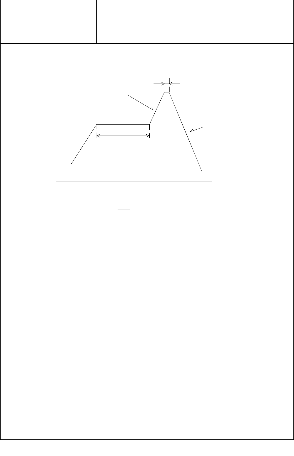
A. Testing : Put on the receptacle connector to PCB , apply the heat 2 cycles as shown in Fig. 4
B.Requirements : Appearance no abnormality adversely affecting the performance shall occur.
A.試験法:基板にリセプタクルコネクタを置き、Fig.4の条件で2回リフローを行う。
B.必要条件:機能を損なう変形及び欠陥の無い事。
Form.Rev.0
I-PEX CO.,LTD sheet 9 of 9
DOCUMENT CLASSIFICATION TITLE No.
Product Specification MHF series micro coaxial PRS-1180
製品規格 connector
433~473K
(160~200
℃
)
1~2 minutes
533(260
℃
)
10±0.5 sec.
Fig.4
Temp.
Time
Gradient
1 ~ 4 K/sec.
Gradient
-3 ~ - 6 K/sec.
Form.Rev.0

z PCB

z Sony T4000