HP 9085mfp (English) System Administrator Guide C00064673
User Manual: HP HP 9085mfp - (English) System Administrator Guide
Open the PDF directly: View PDF ![]() .
.
Page Count: 360 [warning: Documents this large are best viewed by clicking the View PDF Link!]
- Front Cover
- Copyright
- Introduction
- Contents
- Section 1: Safety Information
- Section 2: Machine Information
- Section 3: Copying Operations
- Section 4: Job Memory & Help Mode
- Section 5: Troubleshooting
- Section 6: Machine Specifications
- Section 7: Advanced Information
- Section 8: Special Original
- Section 9: Applications
- Section 10: Image Store Function
- Section 11: Paper and Original Information
- Section 12: Maintenance & Supplies
- Section 13: Key Operator Mode
- Index
- Features of the hp 9085mfp
- Basic Cover
- Section 1: Safety Information
- Section 2: Machine Information
- Section 3: Copying Operations
- Positioning Originals
- Setting Print Quantity
- Setting Job During Warm-up
- To Stop Scanning/Printing
- Selecting Paper Size
- Selecting Magnification Ratio (Lens Mode)
- Selecting Density Level
- Making Double-Sided Copies (1-2, 2-2)
- Making Single-Sided Copies from Double-Sided Originals (2-1)
- Copying Using Special Paper (Multi-Sheet Bypass Tray)
- Copying Using Memory
- Output Mode for Machine without Finisher
- Output Mode for Machine with Finisher
- Selecting Binding Mode
- Recalling Previous Job Settings
- Checking Feature Selections and Proof Copying
- Interrupt Copying
- Section 4: Job Memory & Help Mode
- Section 5: Troubleshooting
- When “Call for Service” Message Is Displayed
- Preventive Maintenance
- Clearing Mishandled Paper
- When “JAM” Appears on Folder Key (Or Arrow Key Flashes)
- When “ADD PAPER” Appears on Folder Key (Or Arrow Key Flashes)
- When “Memory Full” Message Is Displayed (Memory Overflow)
- When Power OFF/ON Screen Is Displayed
- Troubleshooting Tips
- Section 6: Machine Specifications
- Advanced Cover
- Section 7: Advanced Information
- Section 8: Special Original
- Section 9: Applications
- To Display Application Selection Screen
- Inserting Sheets and Covers (Sheet/Cover Insertion)
- Locating Title Pages on the Right Side (Chapter)
- Lay Out Several Pages onto One Sheet (Combination)
- Making a Multiple Page Signature Booklet (Booklet)
- Copying onto Transparent Films (OHP Interleave)
- Inserting Images into Printed Sets (Image Insert)
- Dividing an Image into Right and Left Pages (Dual Page)
- Programming Different Settings for an Output Job (Program Job)
- Erasing Outside of the Original (Non-Image Area Erase)
- Reversing Colour in Black and White Image (Reverse Image)
- Repeating Selected Image Area (Repeat: Vert./Horiz. Mode)
- Repeating Automatically or Selecting Repeating Times (Repeat: AUTO/ Repeat Mode)
- Eliminating Black Copy Marks Along Borders (Frame/Fold Erasure)
- Copying Image in the Centre of Copy Paper (AUTO Layout)
- Printing Images Fully to the Edges (Full-Image Area)
- Adjusting Position of Copy Image (Image Shift)
- Reducing Images to Create Binding Margin (Reduce&Shift)
- Printing Stamp, Page, Date/Time onto Copies (Stamp)
- Printing Watermark onto Copies (Stamp)
- Overlaying an Image onto Each Page Copied in the Job (Overlay)
- Storing an Overlay Image in HDD / Overlaying Image Stored in HDD (Overlay Memory)
- Section 10: Image Store Function
- Section 11: Paper and Original Information
- Section 12: Maintenance & Supplies
- Section 13: Key Operator Mode
- How to Access the Key Operator Mode
- [1] System Initial Setting
- [2] mfp Initial Setting
- [3] User Setting Mode
- [4] E.K.C. (Electronic Key Counter) Function Setting
- [5] Lock/Delete Job Memory
- [6] Paper Type / Special Size Set
- [7] Panel Contrast / Key Sound Adjustment
- [8] Key Operator Data Setting
- [9] Weekly Timer
- [10] Control Panel Adjustment
- [11] Tray Auto Select Setting
- [12] Power Save Setting
- [13] Memory Switch Setting
- [14] Machine Management List Print
- [15] Call Remote Centre
- [16] Side 2 Lens Adjustment
- [17] Finisher Adjustment
- [18] HDD Management Setting
- [19] Scan Transmission Setting
- [20] Non-Image Area Erase Setting
- [21] Timing Adjustment
- [22] Centring Adjustment
- Index
- Back Cover
System
administrator
hp 9085mfp
guide
Copyright and License
© 2003 Copyright Hewlett-Packard Development Company, L.P.
Reproduction, adaptation, or translation without prior written permission
is prohibited, except as allowed under the copyright laws.
The information contained herein is subject to change without notice.
The only warranties for HP products and services are set forth in the
express warranty statements accompanying such products and services.
Nothing herein should be construed as constituting an additional
warranty. HP shall not be liable for technical or editorial errors or
omissions contained herein.
Edition 1: 10/ 2003
FCC Regulations
This equipment has been tested and found to comply with the limits for a
Class A digital device, pursuant to Part 15 of the FCC rules. These limits
are designed to provide reasonable protection against harmful
interference in a residential installation. This equipment generates, uses,
and can radiate radio frequency energy. If this equipment is not installed
and used in accordance with the instructions, it may cause harmful
interference to radio communications. However, there is no guarantee
that interference will not occur in a particular installation. If this
equipment does cause harmful interference to radio or television
reception, which can be determined by turning the equipment off and
on, the user is encouraged to try to correct the interference by one or
more of the following measures:
Reorient or relocate the receiving antenna. Increase separation between
equipment and receiver.
Connect equipment to an outlet on a circuit different from that to which
the receiver is located.
Consult your dealer or an experienced radio/TV technician.
Any changes or modifications to the printer that are not expressly
approved by HP could void the user's authority to operate this
equipment. Use of a shielded interface cable is required to comply with
the Class A limits of Part 15 of FCC rules. For more regulatory
information, see the hp 9085mfp user's guide. Hewlett-Packard shall not
be liable for any direct, indirect, incidental, consequential, or other
damage alleged in connection with the furnishing or use of this
information.
Trademark Credits
PostScript® is a trademark of Adobe Systems Incorporated.
Windows® is a U.S. registered trademark of Microsoft Corporation.
Part number: Q3218-90901

This Manual deals with making copies, correct handling of the machine, and
precautions for safety. Please read before copying.
In order to maintain a satisfactory copying performance, please keep this
Manual readily available for reference in the rear pocket of the machine.
ENERGY STAR® Program
Auto Low Power
This function conserves energy by lowering the set temperature of the fixing
unit. In the standard setting, Auto Low Power operates automatically when 15
in the ready to copy state during that time.
The time period for the Auto Low Power function can be set for 5 minutes, 10
minutes, 15 minutes, 30 minutes, 60 minutes, 90 minutes, 120 minutes, or 240
minutes. See p. 2-20 for details.
Automatic Shut-Off
This function achieves further energy conservation by partially turning OFF the
power supply, thereby reducing energy consumption to 20W or less. In the
standard setting, Automatic Shut-Off follows Auto Low Power, operating
automatically when 90 minutes have elapsed after completion of the last copy,
The time period for the Automatic Shut-Off function can be set for 30 minutes,
60 minutes, 90 minutes, 120 minutes or 240 minutes. See p. 2-20 for details.
Automatic Duplex Copying
To reduce paper consumption, use this function to make double-sided (duplex)
copies, automatically.
We recommend that you utilize the Auto Low Power function, the Automatic
Shut-Off function, and the Automatic Duplex Copying function.
Thank you very much for your purchase of the hp 9085mfp.
The ENERGY STAR Program has been established
to encourage the widespread and voluntary use of
energy-efficient technologies that reduce energy
consumption and prevent pollution. As an ENERGY
STAR Partner, Hewlett-Packard Corporation, Inc. has
determined that this product meets the ENERGY
STAR guidelines for energy efficiency grounding it on
the following features.
minutes have elapsed after completion of the last copy, with the mfp remaining
with the mfp remaining in the ready to copy state during that time.
blank page

i
2
1
3
4
5
6
7
8
9
10
11
13
12
Safety
Information
Machine
Information
Copying
Operations
Job Memory
&Help Mode
Trouble-
shooting
Machine
Specifications
Advanced
Information
Applications
Maintenance
& Supplies
Paper &
Original Info
Function
Key Operator
Mode
Special
Original
Contents
Contents
Basic
Section 1: Safety Information
Caution Labels and Indicators ............................................................................1-2
Machine Configuration ........................................................................................ 2-2
Control Panel Layout .............................................................................................2-16
Turning On the Power Switch ...........................................................................2-17
To Turn On the Power ............................................................................................2-17
To Turn Off the Power ............................................................................................2-19
Reducing the Power in Standby Mode (Auto Low Power) .....................................2-20
Shutting Off Automatically (Auto Shut-Off) ............................................................2-20
Shutting Off / Reducing the Power Manually .........................................................2-21
Loading Paper...................................................................................................2-23
Loading Paper in Multi-Sheet Bypass Tray............................................................2-27
Loading Tabbed Sheets in Tray 1, 2, or 3 ..............................................................2-28
1
Safety
Information
2
Machine
Information
Features of the hp 9085mfp.
Section 2: Machine Information
Internal Machine Items.............................................................................................2-4
Standard/Optional Equipment..................................................................................2-5
8
Q3221A Post Insertion Unit......................................................................................2-
Q3224A Trimmer Unit ............................................................................................2-10
Q3222A/Q5684A Hole Punching Unit ....................................................................2-12
Basic Screen..........................................................................................................2-14
Q322·3A/Q5685A Hole Punching/Z-Folding Unit....................................................2-13
Loading Paper in Tray 1, 2, and 3..........................................................................2-23
Loading Tabbed Sheets in Multi-Sheet Bypass Tray .............................................2-30
Q3637A/Q3638A Tray 4 /HCI...................................................................................2-9
Image Store
Loading Tabbed Sheets in HCI (Q3637A/Q3638A)................................................2-29
Q3219A/Q3220A Finishers.......................................................................................2-6
Entering an ECM Password (ECM)........................................................................2-22
Loading Paper in HCI (Q3637A/Q3638A)...............................................................2-25
Requirements for Safe Use.................................................................................1-6
Environment.............................................................................................................1-7
External Machine Items ...........................................................................................2-2
Power Source ..........................................................................................................1-6
Precautions for Routine Handling ..........................................................................1-10

Contents (continued)
ii
Section 3: Copying Operations
Positioning Originals ...........................................................................................3-2
Setting Print Quantity ..........................................................................................3-7
To Set Print Quantity ................................................................................................3-7
To Change Print Quantity.........................................................................................3-7
Setting Job During Warm-up...............................................................................3-8
To Stop Scanning/Printing.................................................................................3-10
Selecting Paper Size......................................................................................... 3-11
To Select Paper Size Automatically (APS).............................................................3-11
To Specify Desired Paper Size (AMS) ...................................................................3-13
Selecting Magnification Ratio (Lens Mode) ......................................................3-15
To Copy in Fixed Magnification Mode (RE)............................................................3-16
To Copy in Zoom Mode..........................................................................................3-17
Selecting Density Level.....................................................................................3-18
To Select Copy Density..........................................................................................3-18
Density Shift...........................................................................................................3-20
Using Platen Glass ................................................................................................3-24
Copying Using Special Paper (Multi-Sheet Bypass Tray).................................3-29
Copying Using Memory.....................................................................................3-32
To Scan Originals into Memory (Store Mode) ........................................................3-32
To Set Next Copying Job (Reserve).......................................................................3-34
To Check/Control Jobs in Progress (Job Status Screen).......................................3-37
Output Mode for Machine without Finisher .......................................................3-40
Output Mode for Machine with Finisher ............................................................3-43
Selecting Binding Mode ....................................................................................3-48
Recalling Previous Job Settings .......................................................................3-49
Checking Feature Selections and Proof Copying .............................................3-50
Interrupt Copying ..............................................................................................3-53
Section 4: Job Memory & Help Mode
Storing Job Conditions (Job Memory: Job Store) ...............................................4-2
Recalling Stored Job Settings (Job Memory: Job Recall)...................................4-5
Displaying Screen for Operation Guide (Help Mode)..........................................4-6
To Display Help Screen from Basic Screen .............................................................4-6
To Display Help Screen from Other Screens ...........................................................4-8
3
Copying
Operations
4
Job Memory
&Help Mode
Positioning Original on Platen Glass........................................................................3-6
Positioning Originals in RADF..................................................................................3-2
To Copy in 1.00 Magnification Mode......................................................................3-15
Making Double-Sided Copies (1u2, 2u2) ........................................................3-21
Making Single-Sided Copies from Double-Sided Originals (2u1) ....................3-27
Using RADF ...........................................................................................................3-21

Contents (continued)
iii
Section 5: Troubleshooting
When “Call for Service” Message Is Displayed...................................................5-2
Preventive Maintenance .....................................................................................5-4
To Check the PM Counter........................................................................................5-4
Clearing Mishandled Paper.................................................................................5-6
When “JAM” Appears on Folder Key (Or Arrow Key Flashes)............................5-8
When “ADD PAPER” Appears on Folder Key (Or Arrow Key Flashes) ............5-10
Memory Overflow in Reserve Job..........................................................................5-12
When Power OFF/ON Screen Is Displayed......................................................5-13
Section 6: Machine Specifications
Option Specifications ..........................................................................................6-3
Others ......................................................................................................................6-5
5
Trouble-
shooting
6
Machine
Specifications
2
1
3
4
5
6
7
8
9
10
11
13
12
Safety
Information
Machine
Information
Copying
Operations
Job Memory
&Help Mode
Trouble-
shooting
Machine
Specifications
Advanced
Information
Applications
Maintenance
& Supplies
Paper &
Original Info
Function
Key Operator
Mode
Special
Original
Q3224A Trimmer Unit ..............................................................................................6-3
Q3222A/Q5684A Punching Unit ..............................................................................6-4
Q3223A/Q5685A Punching/Z-Folding Unit...............................................................6-4
RADF (Q5682A)...................................................................................................... 6-3
Engine Specifications..........................................................................................6-2
Memory Unit.............................................................................................................6-5
Q3638A Tray 4 /HCI.................................................................................................6-4
Image Store
Limited Use of the mfp in Trouble ...........................................................................5-3
When “Memory Full” Message Is Displayed (Memory Overflow)....................... 5-11
Troubleshooting Tips.........................................................................................5-14
Memory Overflow in Current Job ............................................................................5-11
Engine......................................................................................................................6-2
Q3219A/Q3220A In-Bin Stapler Finisher .................................................................6-3
Q3637A Tray 4 /HCI.................................................................................................6-4
Q3221A Cover Sheet Feeder ...................................................................................6-3

Contents (continued)
iv
Advanced
Section 7: Advanced Information
Programmed Shut-Off (Weekly Timer)................................................................7-2
Rotation...............................................................................................................7-4
Vertical/Horizontal Zoom Mode...........................................................................7-5
Making Folded Booklet (Fold / Stitch&Fold)........................................................7-8
Punching File Holes in Copies (Punch) ............................................................ 7-11
Output Z-Folded Copies (Z-Fold)......................................................................7-14
Making Trimmed Booklet (Trimming) ................................................................7-16
Cover Sheet Feeding........................................................................................7-19
Using Finisher Manually....................................................................................7-22
To Stop Scanning/Printing......................................................................................7-28
Troubleshooting .....................................................................................................7-29
Section 8: Special Original
Section 9: Applications
To Display Application Selection Screen.............................................................9-2
Inserting Sheets and Covers (Sheet/Cover Insertion) ........................................9-3
Locating Title Pages on the Right Side (Chapter)...............................................9-7
Lay Out Several Pages onto One Sheet (Combination) ...................................9-10
Making a Multiple Page Signature Booklet (Booklet)........................................9-13
Copying onto Transparent Films (OHP Interleave) ...........................................9-16
Inserting Images into Printed Sets (Image Insert).............................................9-18
Dividing an Image into Right and Left Pages (Dual Page)................................9-21
Programming Different Settings for an Output Job (Program Job) ...................9-25
Erasing Outside of the Original (Non-Image Area Erase).................................9-27
Reversing Colour in Black and White Image (Reverse Image).........................9-29
Repeating Selected Image Area (Repeat: Vert./Horiz. Mode) ..........................9-31
Repeating Automatically or Selecting Repeating Times
(Repeat: AUTO/ Repeat Mode)...............9-34
7
Advanced
Information
8
Special
Original
9
Applications
Specifying Original Direction............................................................................... 8-2
Making Copy Quality Closer to Originals (Text/Photo Enhance).........................8-4
Copying Mixed Size Originals (Mixed Original)...................................................8-6
Copying Z-Folded Originals (Z-Folded Original) .................................................8-8
Copying Non-Standard Size Originals (Original Form) .....................................8-12
Feeding Single Original from RADF (SDF) .......................................................8-10
Using Two mfps in Tandem ...............................................................................7-25

Contents (continued)
v
Section 9: Applications (continued)
Eliminating Black Copy Marks Along Borders (Frame/Fold Erasure) ...............9-37
Copying Image in the Centre of Copy Paper (AUTO Layout) ...........................9-40
Printing Images Fully to the Edges (Full-Image Area) ......................................9-42
Adjusting Position of Copy Image (Image Shift) ...............................................9-44
Reducing Images to Create Binding Margin (Reduce&Shift)............................9-47
Printing Stamp, Page, Date/Time onto Copies (Stamp)....................................9-50
Printing Watermark onto Copies (Stamp) .........................................................9-56
Overlaying an Image onto Each Page Copied in the Job (Overlay) .................9-59
Storing an Overlay Image in HDD /
Overlaying Image Stored in HDD (Overlay Memory) ..........9-61
To Use Server Functions...................................................................................10-2
Section 11: Paper and Original Information
Paper Information ............................................................................................. 11-2
Paper Weight .........................................................................................................11-2
Tray/ Exit Tray Capacity.........................................................................................11-3
Paper Size .............................................................................................................11-5
Special Paper in Multi-Sheet Bypass Tray.............................................................11-7
To Store Copy Paper..............................................................................................11-7
Original Information........................................................................................... 11-8
10
Function
11
Paper &
Original Info
2
1
3
4
5
6
7
8
9
10
11
13
12
Safety
Information
Machine
Information
Copying
Operations
Job Memory
&Help Mode
Trouble-
shooting
Machine
Specifications
Advanced
Information
Applications
Maintenance
& Supplies
Paper &
Original Info
Function
Key Operator
Mode
Special
Original
Platen Glass Originals ...........................................................................................11-8
RADF Originals ......................................................................................................11-9
Storing/Deleting Image Data in HDD (Image Store/Delete)..............................10-4
To Store Image Data in HDD .................................................................................10-4
Section 10: Image Store Function
Recalling Image Data from HDD (Image Recall) ............................................10-14
Storing Image Data While Copying (Image Store & Output)...........................10-11
To Delete Image Data from HDD ...........................................................................10-8
Image Store
Image Store

Contents (continued)
vi
Section 12: Maintenance & Supplies
Cleaning the Document Glass .............................................................................12-13
Cleaning the Left Partition Glass .........................................................................12-13
Checking Copy Count .....................................................................................12-15
To Display the Counter List Screen......................................................................12-15
To Print the Counter List ......................................................................................12-16
Section 13: Key Operator Mode
How to Access the Key Operator Mode............................................................13-2
To Display the Key Operator Mode Screen............................................................13-2
[1] System Initial Setting ...................................................................................13-4
[1] Date & Time Setting ..........................................................................................13-4
[2] Language Select Setting...................................................................................13-6
[3] IP Address Setting ............................................................................................13-7
12
Maintenance
& Supplies
13
Key Operator
Mode
Adding Toner.....................................................................................................12-2
Empty Waste Basket of Q3222A/Q5684A/Q3223A/Q5685A
Hole Punching Z - Folding Unit .................................................................12-9
Empty Waste Basket of Q3224A Trimmer Unit ............................................... 12-11
Cleaning the RADF Platen Guide Cover..............................................................12-14
Cleaning Image Scanning Section..................................................................12-13
Inserting a New Staple Cartridge into Q3219A/Q3220A Finisher .....................12-5
[4] E-Mail Transmission Setting .............................................................................13-7
[3] User Setting Mode .....................................................................................13-10
[2] User Density Level 2 Setting...........................................................................13-11
[1] User Density Level 1 Setting...........................................................................13-10
[3] User Lens Mode Ratio Setting ........................................................................13-12
[5] Lock/Delete Job Memory ...........................................................................13-20
[6] Paper Type / Special Size Set ...................................................................13-21
[7] Panel Contrast / Key Sound Adjustment....................................................13-23
[8] Key Operator Data Setting.........................................................................13-24
[9] Weekly Timer .............................................................................................13-25
How to Access the Weekly Timer Setting Mode ..................................................13-26
[1] Weekly Timer On/Off Setting ..........................................................................13-27
[2] Timer Setting...................................................................................................13-28
[3] Timer Action On/Off Setting ............................................................................13-30
[4] Lunch Hour Off Setting ...................................................................................13-32
[5] Timer Interrupt Password Setting ...................................................................13-33
[10] Control Panel Adjustment ........................................................................13-34
[11] Tray Auto Select Setting........................................................................... 13-35
[12] Power Save Setting .................................................................................13-36
[13] Memory Switch Setting ............................................................................13-37
[4] E.C.M. (Electronic Key Counter) Function Setting ....................................13-13
How to Access the ECM Setting Mode................................................................13-14
[1] E.C.M. Data Edit.............................................................................................13-15
[2] E.C.M. All Count Reset...................................................................................13-18
[3] E.C.M. Function Setting..................................................................................13-19
[2] mfp Initial Setting.........................................................................................13-8

Contents (continued)
vii
Section 13: Key Operator Mode (continued)
Index
2
1
3
4
5
6
7
8
9
10
11
13
12
Safety
Information
Machine
Information
Copying
Operations
Job Memory
&Help Mode
Trouble-
shooting
Machine
Specifications
Advanced
Information
Applications
Maintenance
& Supplies
Paper &
Original Info
Function
Key Operator
Mode
Special
Original
Image Store
[14] Machine Management List Print ..............................................................13-43
[15] Call Remote Centre .................................................................................13-44
[16] Side 2 Lens Adjustment...........................................................................13-45
[17] Finisher Adjustment .................................................................................13-46
[18] HDD Management Setting.......................................................................13-48
[19] Scan Transmission Setting ......................................................................13-50
[20] Non-Image Area Erase Setting ................................................................ 13-52
[21] Timing Adjustment ...................................................................................13-53
[22] Centering Adjustment ..............................................................................13-55

viii
• AE - Automatic Exposure
Automatically adjusts exposure to compensate for quality of the original.
• AMS - Automatic Magnification Selection
Automatically selects an appropriate magnification ratio when Paper Size is selected
manually. Automatically selected when the AMS key is touched.
• APS - Automatic Paper Selection
Automatically selects copy paper size to match the original documents.
• ATS - Automatic Tray Switching
Automatically switches tray to allow copying to continue without interruption if the
selected tray empties while copying is in progress.
• Auto Layout
The original image on the platen glass or in the document feeder is copied and centred
on a sheet.
• Auto Low Power
• Auto Reset
• Auto Shut-Off
• Booklet
copy mode.
• Chapter
Starts chapter pages on the right side (front pages) of the finished document. Only
• Combination
Copies a fixed number (2, 4, or 8) of pages onto one sheet of copy paper to create a
draft copy of a multi-page report at the same time as saving paper.
• Copy Density
Manually selects up to 9 density levels.
• Copy Mode
• Counter List
Displays on the screen and prints the following data: total counter of the machine,
• Density Shift
Shifts each of nine density levels in four density modes (Auto, Text, Photo, Increase
Contrast) to three levels lighter or three levels darker.
Features of the hp 9085mfp
Creates a multiple page signature booklet copied on both sides of paper in 1u2 or 2u2
duplex mode (1u2) is compatible with this feature.
Selects the desired simplex mode (1u1 or 2u1); or duplex mode (1u2 or 2u2).
Automatically lowers the power after a specified period of mfp inactivity.
Automatically resets to auto mode defaults after a specified period of mfp inactivity.
Automatically shuts off the main power after a specified period of mfp inactivity.
mfp counter, print counter and the date when the counter started.

ix
• Dual Page
Copies both pages of an open book or A3/B4 size sheet separately onto two A4/B5 size
mode. You can use the Dual Page mode with the Front or Front/Back cover mode. The
cover page(s) will be scanned and copied normally before image division is performed
on the other pages.
• Frame/Fold Erasure
Erases border and/or fold image area using Frame (1 - 300mm), Fold (1 - 99mm), or
Frame & Fold.
• Full-Image Area
Makes copies printed completely to the edges of the paper to avoid image loss.
• Image Insert
Stores pages in memory from the platen glass, and inserts the pages into a document
copied from the document feeder.
• Image Shift
Creates or removes a binding margin at the top, bottom, right and left edges (shift
amount from 0 ~ 250mm, in 1mm increments); reduces image to prevent image loss
(reduce & shift amount from 0 ~ 250mm, in 1mm increments).
• Interrupt Copying
features for the interrupt job.
• Job Memory
Programs up to 30 jobs and recalls each job by job number, as needed. All compatible
platen glass functions can be programmed into Job Memory directly after they are
selected.
• Job Status
Displays the Job Status Screen to view the current machine status, changes the opera-
tion order of reserve jobs, deletes the unused reserve job, or displays the previous job
list.
• Lens Mode (RE, Zoom)
Selects fixed ratios, four reduction, four enlargement, and three user-set ratios.
Zoom ratios can be selected from 25% ~ 400% in 1% increments.
• Machine Status Confirmation
Displays the current machine status on LCD for confirmation.
• Manual Shut-off
panel.
• Mixed Original
Copies mixed size originals from the document feeder in APS or AMS mode. APS
automatically selects the paper size of each original. AMS mode allows you to select
one paper size for all originals.
Features of the hp 9085mfp (continued)
sheets in 1u1 mode or separately onto each side of one A4/B5 size sheet in 1u2
Interrupts copying-in-progress to perform an urgent copy, using any of the mfp
Shuts off the machine’s power when pressing [SLEEP ON/OFF] on the control

x
•
• Non-Image Area Erase
When copying from the platen glass when the document cover is open, copies only the
image area and not the exposed area of glass, which would otherwise copy as black.
• Non STD Size for Multi-Sheet Bypass Tray
Enters the special paper size to be loaded on the Multi-sheet bypass tray using the
touch screen keypad in order to avoid paper misfeed.
• Non STD Size for Original
• OHP Interleave
Copies onto transparent film and interleave blank or copied paper for each original
copied.
•
Non-Sort, Sort, Staple-Sort, and Group modes using the primary (main) tray
Non-Sort Face Down exit, Non-Sort Face Up exit, Group Face Down exit, and Group
Face Up exit modes using the secondary (sub) tray
Selects an output tray and output mode on the Output Mode popup menu.
• Output for Machine with no Finisher Installed:
Non-sort, Rotation sort, Group, and Rotation group modes are available in combina-
tion with Face down or Face up exit.
Selects an output mode on the Output Mode popup menu.
•
Cover Sheet mode
Manual Finishing mode
For details, see Section 7: Advanced Information.
• Overlay
Scans an original image and overlays it on the pages of another document. For
example, you may want to incorporate a page heading, graphic design or logo into the
pages of your document.
• Overlay Memory
Same as for “Overlay” except the overlay image is stored in memory.
Features of the hp 9085mfp (continued)
Identifies the special original size which the hp 9085mfp cannot detect, in order to
select theoptimal paper size for copying or printing.
Output Mode for Machine with Q3219A/Q3220A Finisher Installed:
Fold and Stitch & Fold modes using the booklet tray (Q3220A only)
Output for Q3219A/Q3220A Finisher with Q3221A Cover Sheet Feeder Installed:
Image Store Function
Store the scanned image data to the HDD.

xi
•
• Platen Memory
Scans documents into memory from the platen glass and/or the document feeder and
inserts the pages into another document copied from the document feeder. If an
incompatible function is selected in this mode, the latter function will not be selected,
and an Error message will be displayed.
•
inactivity, for optimal efficiency. Power is returned after a brief warm up period by
• Program Job
Scans documents into memory while designating different copy conditions for each
original, then prints all the documents collectively.
• Proof Copy
To ensure correct output before running multiple copies, run a proof copy by pressing
[PROOF COPY] on the control panel or touching PROOF COPY on the Check Screen.
•
Punches four holes in output copies.
• Repeat
Selects the horizontal image area across the page, and repeats it down the page as
many times as the repeat width setting (10 ~ 150mm) permits in manual or auto.
• Reserve
• Reverse Image
Reverses the image from black-on-white to white-on-black or vice versa.
•Rotation
Rotates the image before copying when the portrait/landscape orientation of the origi-
nal is different from the orientation of the copy paper.
• Rotation Exit (Rotation Sort / Rotation Group)
When no Finisher is installed, Rotation Exit alternately switches the horizontal and
vertical orientation of each sorted set as it outputs to the exit tray. Be sure to load both
A4 and A4R in separate trays (including the Multi-sheet bypass tray) before selecting
this feature.
• Server Function (option)
Features of the hp 9085mfp (continued)
Punch Mode for Q3219A/Q3220A Finisher with Q3222A/Q5684A Punching
Unit (Q3223A/Q5685A Punching/Z-Folding Unit) Installed:
Scans in subsequent copy jobs while the hp 9085mfp is busy printing or
copying.
Stores image data in the HDD for future printing.
Automatically turns off all but nominal power supply after a specified period of mfp
Multi-sheet bypass tray. By adding an optional HCI, the system total capacity increases
to 6,150 sheets.
Paper Capacity
Sleep
pressing [SLEEP ON/OFF] on the control panel.
Total 2,150 sheets, including two 500-sheet trays, a 1,000 sheet tray, and a 150-sheet

xii
• Sheet/Cover Insertion
Insert up to 30 blank or copied sheets from any tray including the Multi-sheet bypass
tray, or inserts blank or copied front and back covers from any tray including the Multi-
sheet bypass tray to enhance the presentation of multi-page documents.
•Stamp
Prints watermark, regular stamp, date/time, page number, and numbering onto the
output copies to enhance the presentation and usefulness of the copies.
•Staple
Selects the stapling position and number of staples.
• STD Size (Special)
Detects the standard paper sizes which cannot normally be detected when loaded in a
•Tab Paper
Copies onto tabbed sheets from tabbed originals, allowing the image on the tab part of
the original to be printed on the same part of the tabbed copy paper.
•
Works in tandem to distribute a large copying job in half the time of non-tandem mode.
• Text/Photo Enhance
Enhances photo image in Photo mode, regular image in Text/Photo mode, text image in
Text mode, lighter image in Increase Contrast mode.
•
Trim the end of folded or stapled&folded booklets.
• Userset Density (USERSET 1, USERSET 2)
Outputs up to 16 density samples on a total of 4 pages that display 4 samples per page,
then programs the desired density under USERSET 1 and/or USERSET 2.
• Weekly Timer
Off/On daily or weekly, during lunch time, on holidays, and also enables the Timer
Interrupt mode, which allows temporary use of the machine even when the machine is
in the daily, weekly, or holiday Off mode.
•Wide Size Paper
Copies onto paper slightly larger than the specified regular size.
• Z-Folded Original
•
Z-folds (A3) or double-folds (B4) output copies.
Features of the hp 9085mfp (continued)
Trimming Mode for Q3220A Finisher with Q3224A Trimmer Unit Installed:
Punching / Z-Folding Unit Installed:
This feature sets the RADF to accept Z-folded originals.
engine tray or Multi-sheet bypass tray.
Can be set according to the needs of each work environment. Turns engine power
Tandem Mode for Two mfps
Z-Fold Mode for Q3219A/Q3220A Finisher with Q3223A/Q5685A Hole

Basic
2
1
3
4
5
6
Safety
Information
Machine
Information
Copying
Operations
Job Memory
&Help Mode
Trouble-
shooting
Machine
Specifications
blank page

1
1
Safety
Information
Safety Information
Precautions for Installation and Use
Caution Labels and Indicators ................................................................ 1-2
Requirements for Safe Use ................................................................ 1-6
1-2
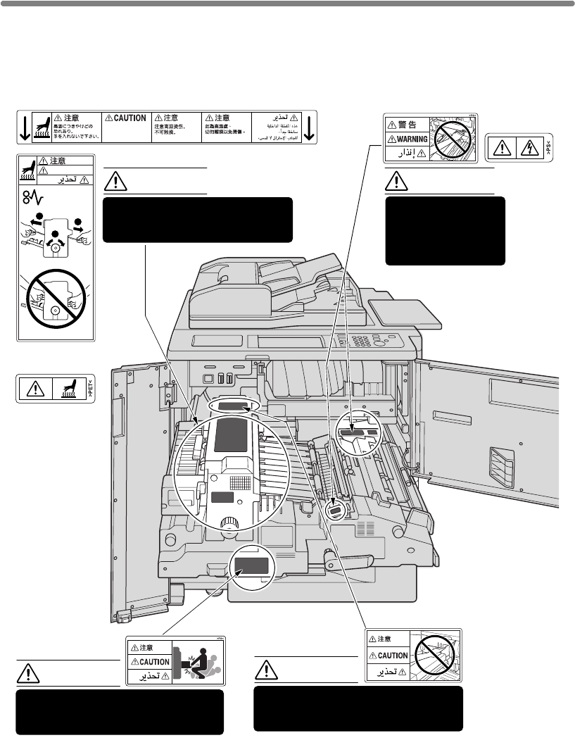
Caution Labels and Indicators
The caution labels and indicators are attached to the machine areas, as shown
below, where you are advised to pay special attention to avoid any dangerous
situations or serious injury.
(Both sides of the fixing unit)
(Front side
and Inside of
the fixing unit)
(Top surface of
the fixing unit)
WARNING
This area generates
high voltage. If
touched, electrical
shock may occur. DO
NOT TOUCH!
CAUTION
The fixing unit is very hot.
To avoid getting burned DO NOT
TOUCH.
CAUTION
DO NOT put your hand between the
unit; otherwise you may be injured.
CAUTION
The fixing conveyance unit is heavy.
Use care and draw it out gently;
otherwise you may be injured.
This internal area is very
hot. To avoid getting
burned, DO NOT TOUCH.
1
2
2
CAUTION
engine and fixing conveyance
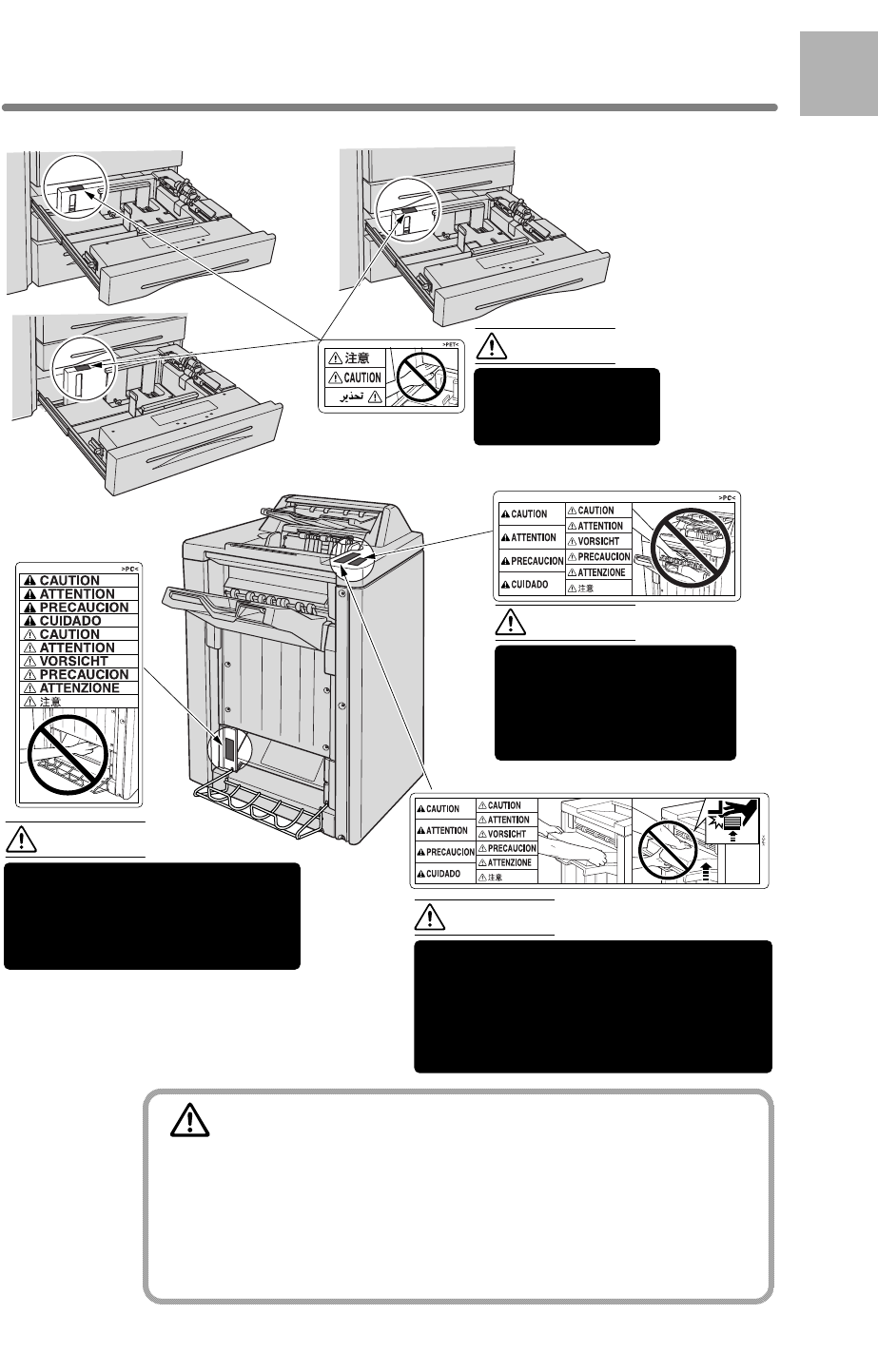
Caution Labels and Indicators (continued)
1-3
CAUTION
Burns or injury may occur from touching the areas detailed in
the caution labels and caution indicators. Do not remove
caution labels or indicators. If any caution label or caution
indicator is soiled, please clean to make legible. If you cannot
make them legible, or if the caution label or indicator is
damaged, please contact your service representative for
replacement labels.
Tray 1
Tray 3
Tray 2
CAUTION
DO NOT put your hand
and tray; otherwise you
may be injured.
Inside the lower paper exit outlet
is the roller drive unit.
DO NOT put your hands into the
paper exit outlet as you may be
injured.
CAUTION
Use care after opening the
paper exit outlet. DO NOT
put your hands into the
paper exit outlet as you
may be injured.
CAUTION
To avoid injury, DO NOT put your hand on
the top of the printed sheets. Be sure to hold
both sides of the printed sheets when
removing them, and DO NOT leave your
hand on the printed sheets while the primary
(main) tray goes up.
CAUTION
1
Safety
Information
Q3220A Finisher
(Q3219A/Q3220A)
(Q3219A/Q3220A)
(Q3220A only)
between the engine
Caution Labels and Indicators (continued)
1-4
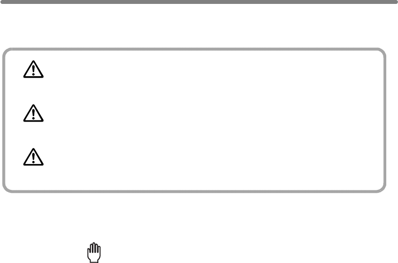
The following indicators are used on the caution labels or in this manual to categorize
the level of safety cautions.
DANGER:
Action highly liable to cause death or serious injury.
WARNING:
Action liable to cause death or serious injury.
CAUTION:
Action liable to cause minor injury, machine trouble or physical damage.
If you find any of these indicators when removing jammed paper, adding toner, or
reading the manual, be sure to follow the information.
Reminder!
If the safety cautions in the manual become illegible due to soilage, etc.,
please procure a new copy from your service representative.

1-5
1
Safety
Information
Regulations
FCC Regulations
Warning: The hp 9085mfp generates, uses, and can radiate radio frequency energy. If it is
not installed and used in accordance with the instruction manual, interference with radio
communications may result. This equipment has been tested and found to comply with the
limits for a Class A computing device, pursuant to Subpart B, Part 15, of FCC rules, which
are designed to provide reasonable protection against interference from such equipment
when it is operating in a commercial environment.
Users operating this equipment in a residential area are likely to cause interference, in
which case they may be required to correct the interference at their own expense.
Canadian Department of Communications Regulations
Le présent appareil n’émet pas de bruits radioélectriques dépassant les limites
applicables aux de Classe A prescrites dans le règlement sur la brouitlage radioélectrique
édicté par Le Ministère des Communications du Canada.
This equipment does not exceed the Class A limits for radio noise emissions as set out in
the radio interference regulations of the Canadian Department of Communications.
FDA Regulations
This Copier is certified as a “Class 1” laser product under the U.S.Department of Health
and Human Service (DHHS) Radiation Performance Standard according to the Radiation
Control for Health and Safety Act of 1968. Since radiation emitted inside this printer is
completely confined within protective housings and external covers, the laser beam cannot
escape during any phase of normal user operation.

1-6
Requirements for Safe Use
To ensure your safe use of the machine, the following describes the precautions you
are required to observe without fail for the power source of the machine and during
installation and routine handling. Be sure to read and observe them.
Power Source
CAUTION: Plug Socket
• A plug socket is limited in capacity. Use only a power source with the correct rating
for the machine; otherwise, hazardous situations such as smoking or overheating
may occur. See the following list to match the power supply and power
consumption:
a) 230V / 50Hz: More than 15A
b) 230V / 60Hz: More than 15A
• Avoid multiple connections in the same outlet. Do not use multiple outlet adaptors.
CAUTION: Power Plug and Cord
• Be sure to insert the power plug firmly into the power socket. Otherwise an
accident may occur as a result of smoking or overheating. If the inserted power
plug is loose in the socket, even after it has been positively inserted, disconnect the
plug and contact your electrical contractor.
• For plug cable equipment, the socket-outlet shall be installed near the equipment
and shall be easily accessible.
in any way, contact your service representative immediately. Do not attempt to
may result in overheating, a short circuit, or fire.
occur as a result of overheating or fire.
CAUTION:
Connecting Multiple Loads to One Socket Outlet Prohibited
Never connect multiple loads to one socket outlet using a multi-outlet extension cord or
branched socket. Otherwise an accident may occur as a result of overheating or fire.
CAUTION: Extension Cord
An extension cord must never be used with this machine.
• Do not bend or crush the power cord. If your mfp power cord is bent or damaged
repair it yourself, and do not continue to operate the mfp. A damaged power cord
• Do not bundle or coil the power cord of the mfp. Otherwise an accident may
1-7
1
Safety
Information
Requirements for Safe Use (continued)
Environment
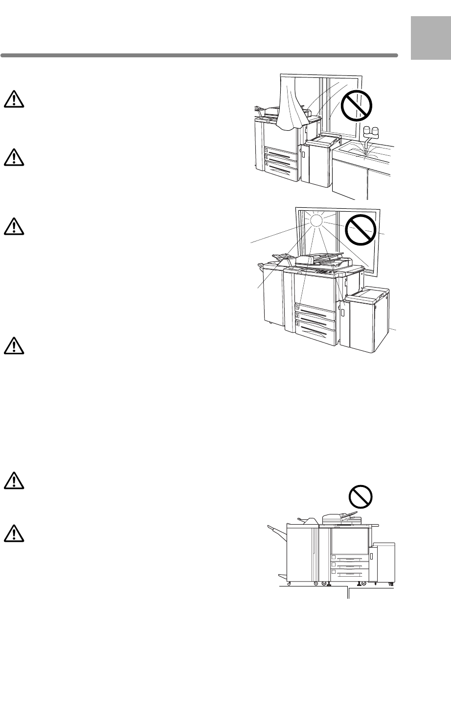
CAUTION: Prevention of Fire
Do not install near flammable materials, curtains and
volatile combustibles, that can catch or cause fire.
CAUTION: Prevention of Short Circuit
with rain water or water from a tap, to avoid a short
circuit.
CAUTION: Temperature and Humidity
• Keep away from direct sunlight, heat sources
such as stoves, cool air from an air conditioner
and hot air from a heater.
• Avoid any environment that is outside the range
shown below:
10 to 30°C in temperature
10 to 80% in humidity
CAUTION: Ventilation
• Maintain the installation place well-ventilated.
• Keep away from dust or corrosive gases. These materials may cause poor image
quality.
• During the use of machine, the machine generates ozone in an insufficient amount
to cause any hazard to the human body.
However, if the machine is used in a poorly ventilated room and many copies are
Ensure adequate ventilation for a comfortable working environment.
CAUTION: Vibration
Do not install on a floor which is subject to vibration or
is not level.
CAUTION: Transportation
Be sure to contact your service representative when
moving or transporting the machine. If you move the
machine with the Hard disk drive or Memory unit
installed, trouble may be caused by vibration.
Do not install the mfp where it could be splashed
made or more than one mfp is used at the same time, an odor may be detected.
1-8
Requirements for Safe Use (continued)
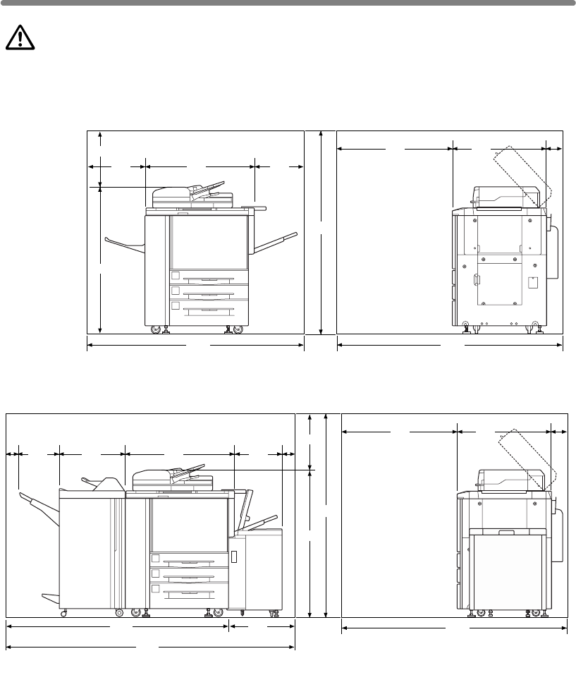
CAUTION: Installation Space
Allow sufficient space for facilitating copy operation, changing parts, and periodic
inspection. Leave an adequate space behind the machine to let hot air out from the
rear fan.
400
1160
1560
(Unit: mm)
400
475 887
1762 1845
775
950 120
2337
1807
546321
100 10 0
887
1160
386
530
400
1560
(Unit: mm)
1845
775
950 120
hp 9085mfp
hp 9085mfp + Finisher + High Capacity Input
1-9
1
Safety
Information
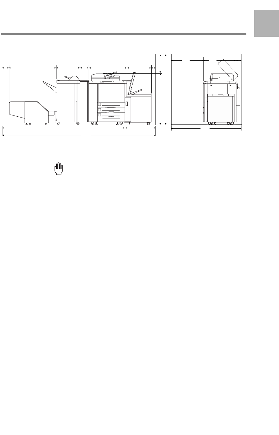
Requirements for Safe Use (continued)
3601
2831 770 1845
775
950
120
1160
400
1560
887
100
150 174
1118 546 626
(Unit: mm)
hp 9085mfp + Multifuntion Finisher + Trimmer unit + Hole Punch Unit + High Capacity Input
Finisher primary (main) tray of Q3219A/Q3220A Finisher gradually goes
interference may cause damage to the finisher.
down while printed materials output. DO NOT allow any object to interfere
Reminder!
with the operation of the tray on the left side of the finisher, as any
1-10
Requirements for Safe Use (continued)
Precautions for Routine Handling
WARNING: High Voltage
DO NOT TOUCH the high voltage parts indicated with WARNING label or described
in the manual.
CAUTION: Actions in Response to Troubles
anymore, stop the operation to prevent any unexpected accident. Write down the
disconnect from the power socket. Contact your service representative and inform
them of the report code.
• Do not touch the high temperature parts indicated with CAUTION labels or
described in the manual.
• Do not touch the inside of the machine for any other purpose than removing
jammed paper or adding toner.
• If machine repair is necessary, be sure to contact your service representative.
Never attempt to repair it by yourself.
• If any abnormal sound, smell or smoke comes from the machine, immediately stop
using it, turn off the power switch, disconnect the power plug and contact your ser-
vice representative.
• If the breaker trips or the fuse blows, turn off the power switch, reset the breaker or
the fuse, and turn on the machine. If the same situation occurs again, contact your
service representative.
• Ensure the replacement fuse conforms with the rating of the power source. Never
use a fuse with an incorrect rating.
CAUTION: Prevention of Fire
Do not use volatile combustibles, such as thinner or alcohol, near the machine.
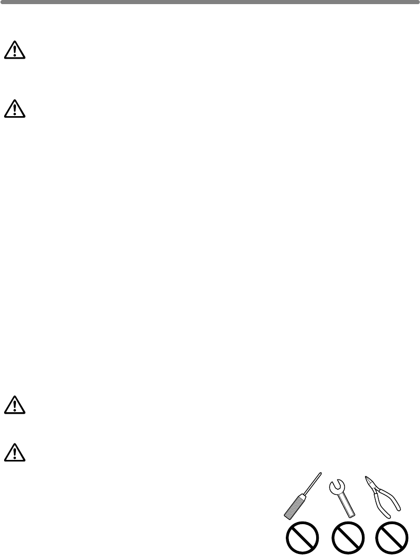
CAUTION: Prohibition of Machine Modification
Do not modify or remove any parts by yourself.
• If the Service Call screen is displayed and mfp operations cannot be continued
report code as stated on the 2nd line of the message, then switch off the mfp and
1-11
1
Safety
Information
Requirements for Safe Use (continued)
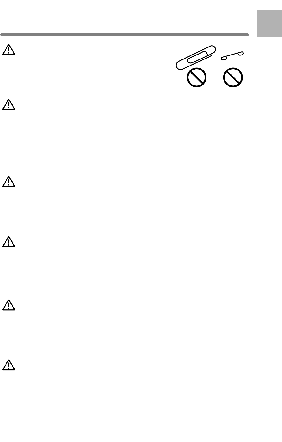
CAUTION: Prevention of Machine Troubles
• Do not drop small metallic objects, such as paper clips
or staples, inside the machine.
• Do not place any heavy or hard objects such as a vase,
books or ornaments on the machine.
CAUTION: Recommendation of Periodic Check
Be sure to periodically check the following points:
(1) The main cord or the power plug does not generate abnormal heat.
(2) The power plug is not inserted loosely or the cord is not cut or scratched.
(3) The grounding wire is correctly connected.
(4) The power plug or the power outlet is not covered with dust.
If you find anything abnormal in the above items, stop using the machine and contact
your service representative.
CAUTION: Toner
• Keep the toner cartridge away from children. The toner is nontoxic; however if you
inhale or it makes contact with eyes by accident, flush with water and seek medical
advice.
• Do not throw the empty toner cartridge into a fire. If it is thrown into a fire the toner
may ignite and cause a dangerous situation.
CAUTION: Paper
Check paper to be sure it conforms to the specifications outlined in Section 11.
• Do not use paper with staples or paper that conducts electricity (silver, carbon,
etc.), otherwise an accident may occur as a result of fire.
• To avoid machine trouble, do not use heat-sensitive paper, paper that conducts
electricity (silver, carbon, etc.), or colored OHP film.
power is still applied to certain areas of the machine. To avoid any unexpected
• When the Weekly Timer function is operating, turning power OFF will disable the
function.
CAUTION: Inside the Booklet Mode Outlet
Inside the Booklet mode outlet is the roller drive unit. DO NOT put your hand into it,
when removing the folded or stapled & folded sheet; otherwise you may be injured.
troubles turn the power OFF when not using the mfp for long periods of time.
CAUTION: Sleep and Weekly Timer
• In Sleep mode the mfp is still connected to the main power supply and

1-12
Requirements for Safe Use (continued)
CAUTION: Finisher Paper Exit Outlet
To avoid injury when stapling large size copies, DO NOT put your hand into the open
Paper Exit Outlet.
CAUTION: Fixing Unit
The internal fixing unit is very hot. To avoid getting burned, DO NOT TOUCH. Be
careful when withdrawing the fixing unit.
WARNING: Drum Unit
The internal drum unit generates a high voltage.
To avoid an electrical shock, DO NOT TOUCH.
arrange for its safe disposal.
If you change the place of installation, please contact your service representative.
CAUTION: Paper Capacity for the Exit Tray
The exit tray capacity is max. 150 sheets. If a copy run of more than 150 is required,
be sure to remove the copies from the exit tray before the maximum capacity is
Select an exit tray and output mode on the Output Mode popup menu.
When the total number of copies in the copy run exceeds the capacity stated in Sec-
When printed materials are removed from the primary (main) tray of the Finisher, the
tray goes up automatically. To avoid injury, DO NOT put your hand on top of the
printed sheets. Be sure to hold both sides of the printed sheets when removing them,
and DO NOT leave your hand on the printed sheets while the primary tray goes up.
CAUTION: Q3219A/Q3220A Finisher Paper Capacity
The Q3219A Finisher is equipped with two exit trays, and Q3220A Finisher is equipped
with three exit trays.
CAUTION: Q3219A/Q3220A Finisher Primary (Main) Tray
CAUTION: Disposal of mfp
Do not dispose of this mfp yourself. Contact your service representative, who can
reached. Failure to do so will cause the mfp to jam.
tion 11, be sure to unload the exit tray while the mfp is still copying. Failure to do so
To prevent paper misfeed, do not exceed the paper capacity of the Finisher.
will cause the mfp to jam.

2
Machine Information
Machine Configuration, Turning On the Power
and Loading Paper
Machine Configuration............................................................................ 2-2
Turning On the Power Switch ........................................................... 2-17
Loading Paper ...................................................................................... 2-23
2
Machine
Information
Machine
Configuration
Turn On/Off
the Power
Loading
Paper
2-2
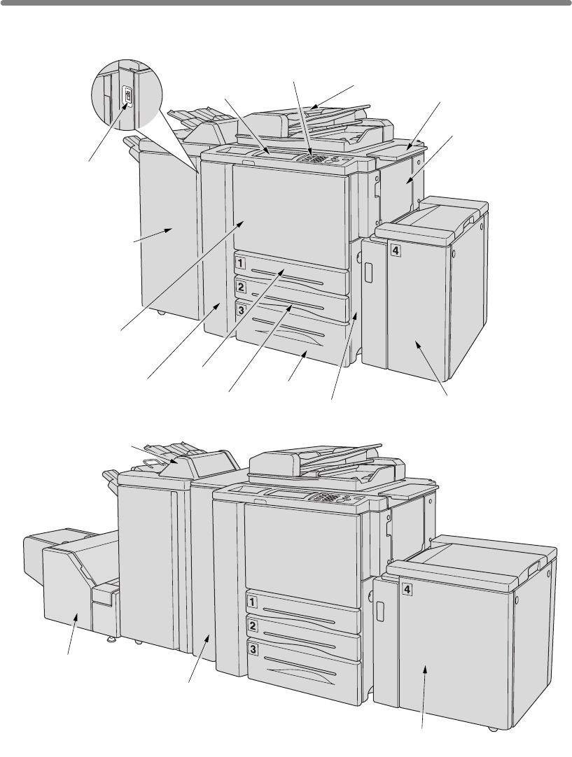
Machine Configuration
External Machine Items
16 LCD touch screen
17 Control panel
2 Work table
3
5 Right side door
(not shown)
6 Tray 3
7 Tray 2
8 Tray 1
9 Left door
10 Front door
12
11
15 Power switch
Q3219A/Q3220A
Finisher (option)
Q3637A (option)
Multi-sheet
bypass tray
14 Cover sheet feeder
Q3221A (option)
13 Q3224A Trimmer unit (option)
Q3222A/Q5684A Punching unit
or Q3223A/Q5685A Punching /
Z-Folding unit (option)
Q3638A (option)
1 RADF
4 Tray 4: tray 4 /HCI
4 Tray 4: tray 4 /HCI

Machine Configuration (continued)
2-3
1
originals one at a time to the platen glass for copying.
2 Work table provides a convenient workspace for documents both before and after
copying.
3 Multi-sheet bypass tray used for small quantity copying onto plain paper or
special paper.
4
5 Right side door opens to allow removal of mishandled paper.
6 Tray 3 (universal tray) is user-adjustable and holds 1,000 sheets.
7
8 Tray 1 (universal tray) is user-adjustable and holds 500 sheets.
9
10 Front door opens to allow removal of mishandled paper.
11
16 LCD Touch screen displays interactive operation screens.
2
Machine
Information
Machine
Configuration
Turn On/Off
the Power
Loading
Paper
and/or Z-folds the output copies.
Q3222A/Q5684A Hole Punching unit (option) punches file holes in the output
copies.
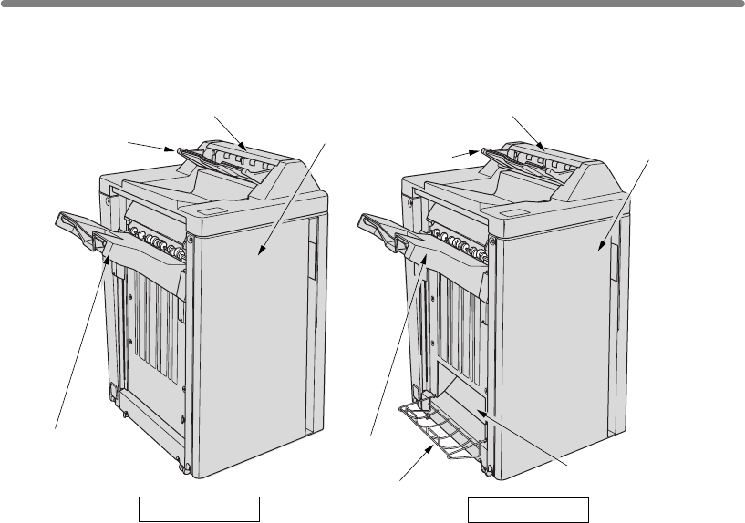
12 Q3219A/Q3220A Finisher (option) sorts, staple-sorts, and groups copies
into finished sets.
Left side door opens together with the front door to allow removal of mishandled
Q3220A also folds or staples & folds copies into booklet-styled sets.
Q3223A/Q5685A Hole Punching / Z-Folding unit (option) punches file holes
13 Q3224A Trimmer unit (option) trims the end of booklet.
14 Q3221A Cover sheet feeder (option) loads cover sheet paper and feeds the
sheetas cover.
15 Power switch turns mfp power On/Off when pressed.
17 Control panel controls mfp operations and displays messages as required.
HCI ( Tray 4 /HCI Q3637A/Q3638A) (option) holds 4,000 sheets.
RADF (Reversing Automatic Document Feeder) automatically feeds multiple
Tray 2 (universal tray) is user-adjustable and holds 500 sheets.
paper, and have access to optional EFI print controller.
Machine Configuration (continued)
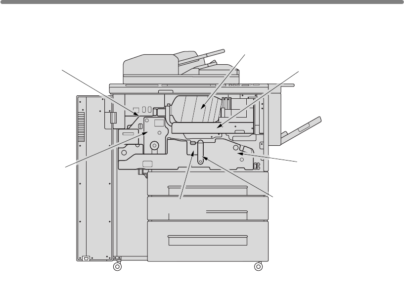
2-4
Internal Machine Items
1 Toner cartridge holds toner and is to be replaced when supplying toner.
2 Toner unit holds the toner supply.
3 Conveyance fixing unit passes the paper through the drum unit, and fuses the
toner onto the copy paper, and is to be withdrawn for removal of mishandled
paper.
4 Lever A can be moved to withdraw the conveyance fixing unit for removal of
mishandled paper.
5 Drum unit forms the copy image.
6 Fixing unit fuses the toner onto the copy paper.
7 Reset switch used only by service representative turns machine power on/off
when pressed.
1 Toner cartridge
2 Toner unit
3Conveyance fixing
unit
4 Lever A
5 Drum unit
6 Fixing unit
7 Reset switch
Machine Configuration (continued)
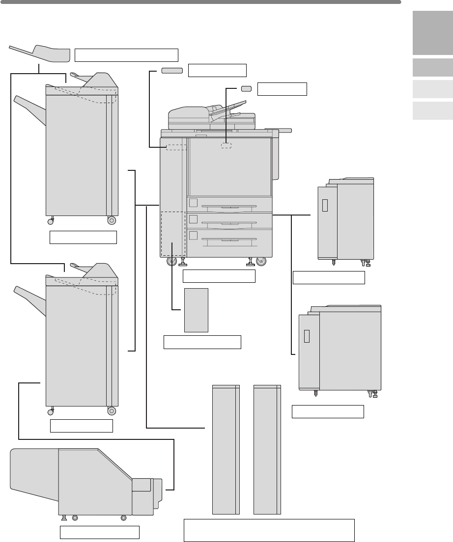
2-5
Standard/Optional Equipment
2
Machine
Information
Machine
Configuration
Turn On/Off
the Power
Loading
Paper
Q3221A Cover sheet feeder
Q3219A Finisher
Q3220A Finisher
Q3224A Trimmer unit Q3222A/Q5684A Hole Punching unit or
Q3223A/Q5685A Hole Punching / Z-Folding unit
Memory unit
Video interface
hp 9085mfp engine
Q3638A tray 4 /HCI
Q3637A tray 4 /HCI
EFI Print controller
Machine Configuration (continued)
2-6
1
Finisher door
opens to the internal Finisher to allow clearing mishandled paper
and replenishing staples.
2
3
4 Primary (Main) tray holds sets output in Non-sort mode, Sort mode (offset),
Staple-sort mode, or Group mode (offset).
5 Secondary (Sub) tray holds sets output in Non-sort mode or Group mode with
face down/up mode.
6 Secondary (Sub) tray cover opens to allow clearing mishandled paper.
1Finisher door
1Finisher door
6Secondary (Sub) tray cover6Secondary (Sub) tray cover
2Booklet mode outlet
3Booklet tray
4Primary
(Main) tray
4Primary
(Main) tray
5Secondary
(Sub) tray
5Secondary
(Sub) tray
Q3219A/Q3220A Finisher
Q3219A Finisher Q3220A Finisher
Booklet mode outlet (Q3220A Finisher only) outputs finished copied sets
when selecting Fold mode or Stitch & Fold mode.
Booklet tray (Q3220A Finisher only) holds sets output in Fold mode or Stitch
& Fold mode.
Machine Configuration (continued)
2-7
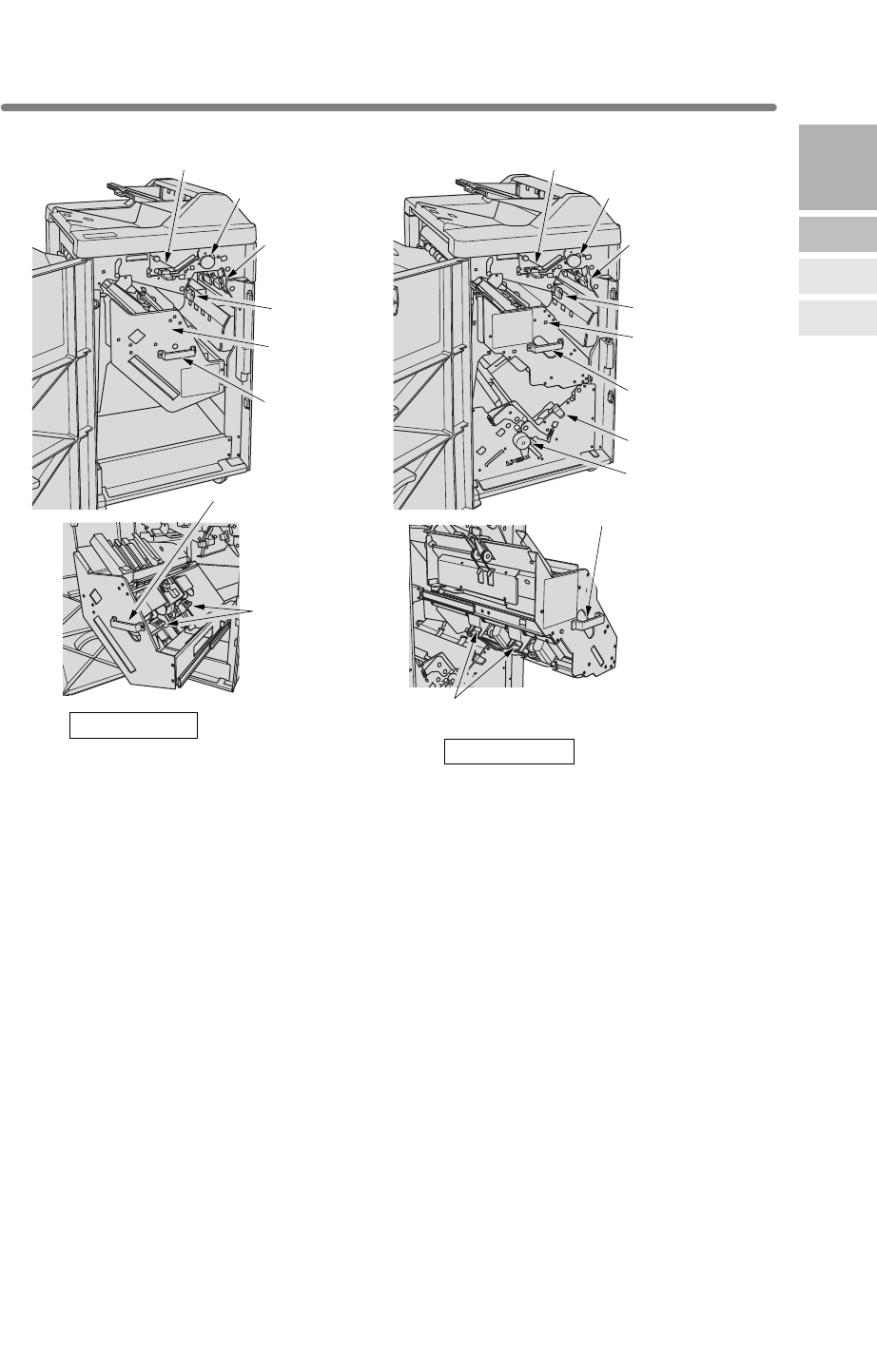
1 Upper lever opens upward to remove mishandled paper.
2 Upper knob can be turned to ease removal of mishandled paper.
3 Right lever opens to remove mishandled paper.
4 Left lever opens to remove mishandled paper.
5
6 Stacker unit handle withdraws unit to allow removal of mishandled paper and
replacement of staple cartridge.
7 Lower lever opens to remove mishandled paper.
8 Knob can be turned to ease removal of mishandled paper.
9 Cartridge housing holds staple cartridge and is to be replaced when supplying
staples.
3Right lever
4Left lever
5Stacker unit
6 Stacker unit
handle
6 Stacker unit handle
6 Stacker unit handle
9 Cartridge housing
2Upper knob
1Upper lever
3Right lever
4Left lever
5Stacker unit
6 Stacker unit
handle
9 Cartridge housing
2Upper knob
1Upper lever
8Knob
7Lower lever
2
Machine
Information
Machine
Configuration
Turn On/Off
the Power
Loading
Paper
Q3219A Finisher
Q3220A Finisher
Stacker unit holds stapler, and also holds the device to provide Fold and Stitch &
Fold mode in Q3220A.
Machine Configuration (continued)
2-8
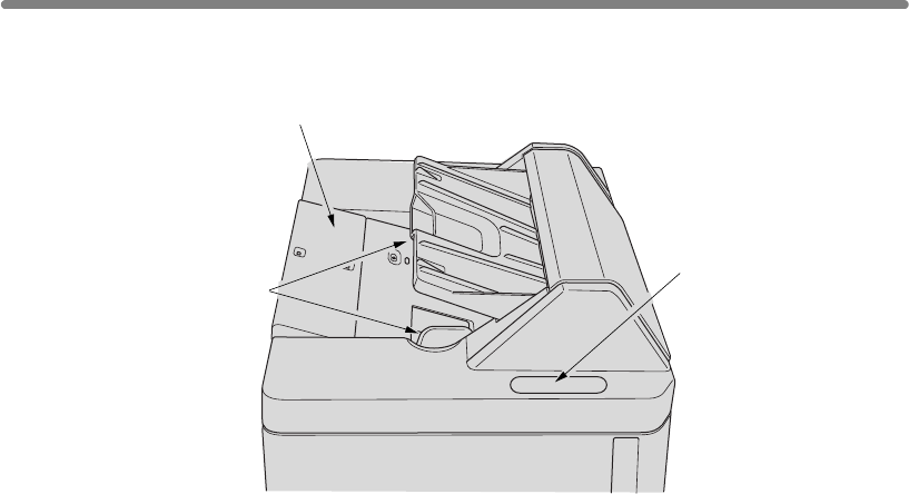
1 Manual finishing operation panel controls cover sheet feeder operations.
2 Cover sheet feeder holds cover sheets for use in cover sheet output mode.
3 Cover sheet feeder guide plates hold cover sheets to fix the position.
1Manual finishing
operation panel
2Cover sheet feeder
3Cover sheet feeder
guide plates
Q3221A Cover Sheet Feeder
Machine Configuration (continued)
2-9
1
2
3
4
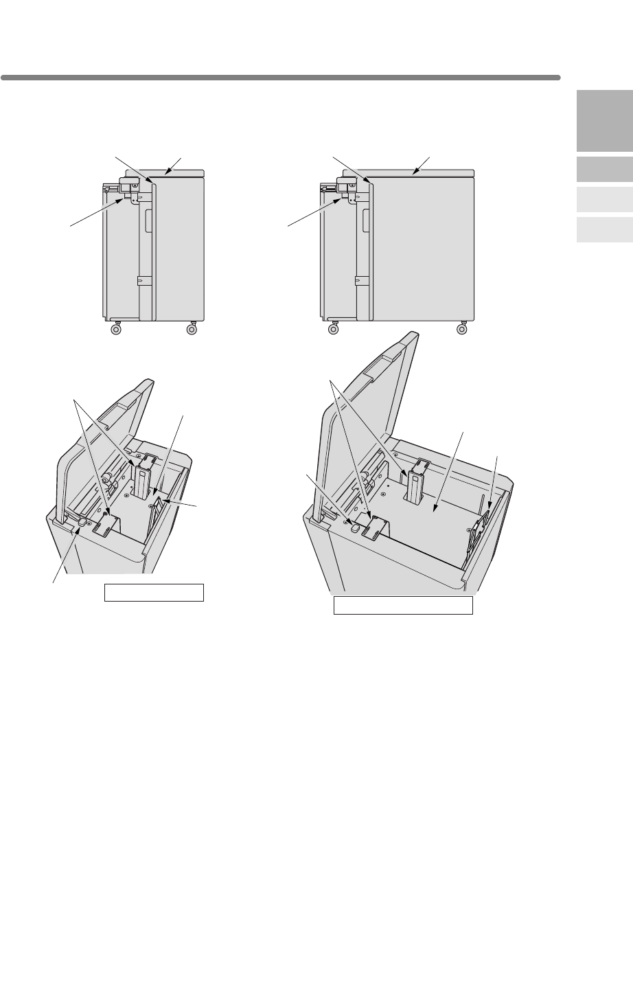
5 Paper loading button is pressed to lower the bottom plate to allow loading paper.
6
goes down when the paper loading button is pressed.
7 Rear stopper fixes the rear end of copy paper.
1
12
side door
2
side door
33
4
4
6
6
5Paper loading
button
5Paper loading
button
7Rear stopper
7Rear stopper
2
Machine
Information
Machine
Configuration
Turn On/Off
the Power
Loading
Paper
Q3637A tray 4 /HCI
Q3638A tray 4 /HCI
HCI top door
HCI left
HCI lever
HCI top door
HCI left
HCI lever
HCI paper guides
HCI paper guides
HCI bottom plate
HCI bottom plate
HCI top door opens to allow paper loading.
HCI left side door opens to allow removal of mishandled paper.
HCI lever can be moved downward to ease removal of mishandled paper.
HCI paper guides hold copy paper to fix the position.
HCI bottom plate goes up automatically when paper supply becomes low, and
Q3637A/Q3638A Tray 4 /HCI
Machine Configuration (continued)
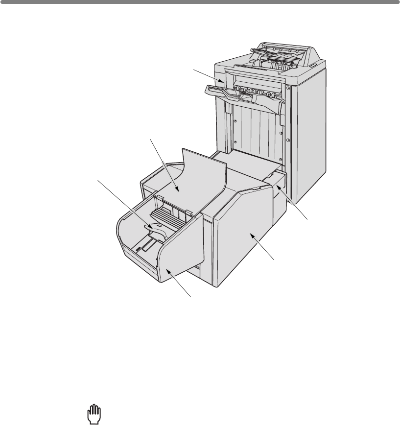
2-10
1 Front-right cover opens to allow removal of mishandled paper.
2 Front door opens to allow removal of mishandled paper or waste paper.
3 Trimmer stacker holds sets output in Trimming mode.
4 Trimmer unit tray slides to the left side each time a trimmed booklet is delivered.
5 Trimmer stacker cover opens to allow you to take out the finished sets.
Reminder!
DO NOT place heavy objects on the trimmer stacker or apply any weight
on it, and DO NOT use it for storage.
Excessive weight applied to the inside or outside of the trimmer stacker
will damage the equipment.
5Trimmer stacker cover
4Trimmer unit tray
2Front door
1Front-right cover
3Trimmer stacker
Q3224A Trimmer Unit
Q3220A Finisher
Machine Configuration (continued)
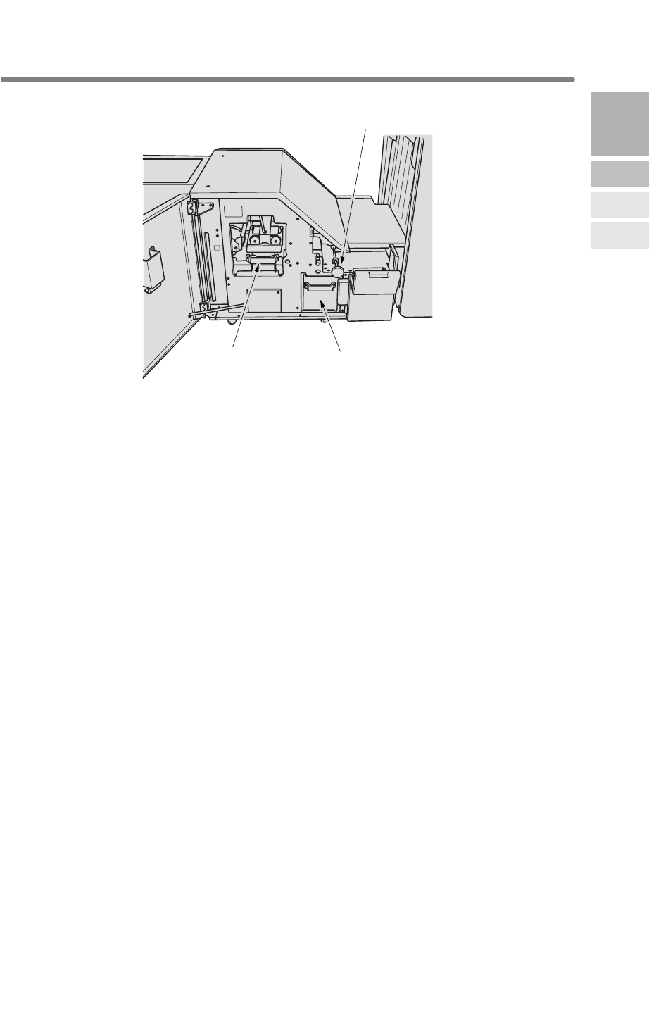
2-11
1 Trimmer unit knob can be turned to ease removal of mishandled paper.
2 Waste basket holds waste paper cut off from the booklets.
3 Trimmer pressure release lever opens to allow removal of mishandled paper.
2Waste basket
1Trimmer unit knob
3Trimmer pressure
release lever
2
Machine
Information
Machine
Configuration
Turn On/Off
the Power
Loading
Paper
Machine Configuration (continued)
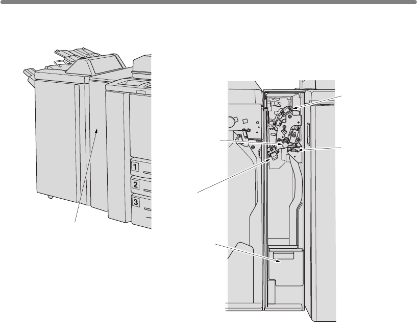
2-12
1
2 Right lever opens to allow removal of mishandled paper.
3 Upper lever opens to allow removal of mishandled paper.
4 Knob can be turned to ease removal of mishandled paper.
5 Left lever opens to allow removal of mishandled paper.
6 Waste basket holds waste paper punched out.
1Punching unit
front door
3Upper lever
2Right lever
4Knob
5Left lever
6Waste basket
Q3222A/Q5684A Hole Punching Unit
Hole Punching unit front door opens to allow removal of mishandled paper or
wastepaper.
Machine Configuration (continued)
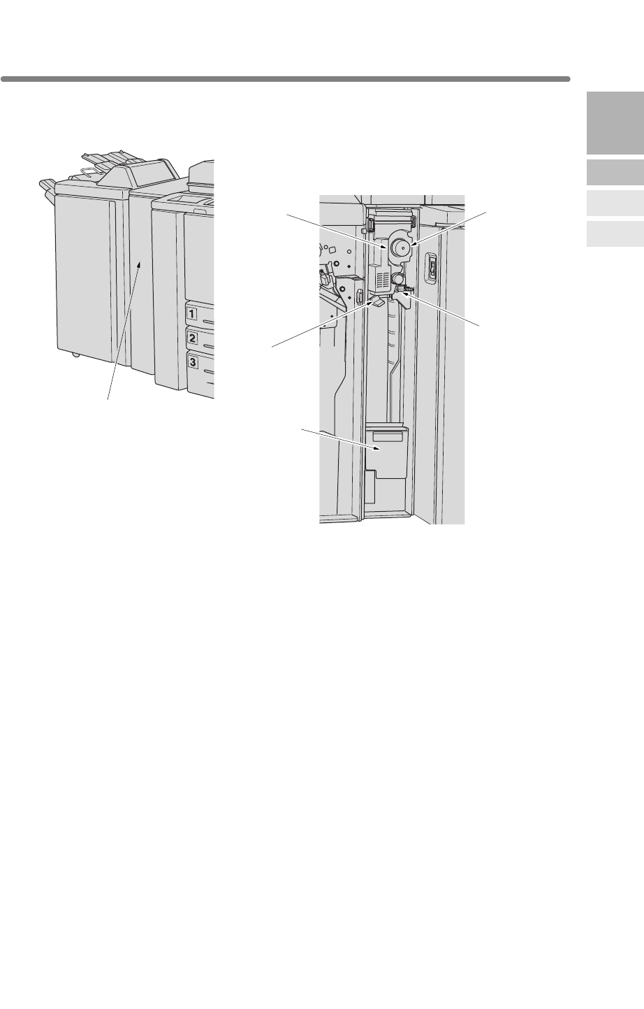
2-13
1
2 Right lever opens to allow removal of mishandled paper.
3 Knob can be turned to ease removal of mishandled paper.
4 Handle can be withdrawn to allow removal of mishandled paper.
5 Left lever opens to allow removal of mishandled paper.
6 Waste basket holds waste paper punched out.
1
3Knob
2Right lever
4Handle
5Left lever
6Waste basket
2
Machine
Information
Machine
Configuration
Turn On/Off
the Power
Loading
Paper
Q3223A/Q5685A Hole Punching / Z-Folding Unit
Hole Punching / Z-Folding
unit front door
Hole Punching / Z-Folding unit front door opens to allow removal of
mishandledpaper or waste paper.
Machine Configuration (continued)
2-14
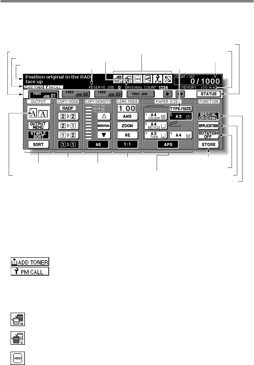
Basic Screen
The Basic Screen displays when copying operation becomes available after warm-
up.
1 Folder keys
FREE JOB is selected to specify a copy job conditions.
When scanning starts, FREE JOB changes to SCAN JOB, then changes to
PRINT JOB when the machine starts printing.
FREE JOB at the right side of SCAN JOB or PRINT JOB can be touched to
specify a reserve job conditions. Up to 10 reserve jobs can be set. The arrow keys
at the right side of folder keys are used to scroll.
2 Notice icons
: ADD TONER icon is displayed when toner supply becomes low.
: PM CALL icon is displayed when preventive maintenance is due.
3 Message area displays the machine status and procedure required at that time.
4 Reserve job counts the reserve jobs already specified.
5 Original count counts the original pages placed in the document feeder as they
are scanned.
6:Master icon is displayed when the TANDEM key is selected on the Output
Mode popup menu.
:HDD icon is displayed when using Image Store & Output mode of Server
function.
1 Folder keys 9 Memory indicator
10 STATUS key
2 Notice icons
6 Master/ Sub/ HDD/ Original
direction/ PM/ Rotation icons
8 Count/Set indicator
11 SPECIAL ORIGINAL key
14 STORE key
15 Paper size area
16 Lens mode area18 Copy mode area
17 Copy density area19 Output mode keys
20 Output icon area 12 APPLICATION key
13 ROTATION OFF key
3 Message area
5 Original count
4 Reserve job 7 TYPE/SIZE key
:Sub icon is displayed when the mfp operates in tandem with the primary
(master) mfp.

Machine Configuration (continued)
2-15
:Original direction icon indicates the original direction
specified on the Special Original popup menu.
:PM icon is displayed when preventive maintenance is due.
:Rotation icon is displayed when Rotation automatically functions.
7 TYPE/SIZE key is touched to specify the type and size of the paper loaded in the
Multi-sheet bypass tray.
8 Count/Set indicator indicates the print quantity entered from the control panel
keypad, and also indicates the print count on the left of the set count while
printing.
9 Memory indicator indicates the remaining memory available for the next
operation.
10 STATUS key is touched to view the current job status, to change the printing
order of reserve jobs, or to cancel printing a reserve job.
11 SPECIAL ORIGINAL key is touched to specify the condition of originals to be
scanned.
12 APPLICATION key is touched to select various application functions.
13 ROTATION OFF key is touched to release the Rotation function.
14 STORE key is touched to store scanned images into memory.
15 Paper size area is used to select the desired paper size or APS.
16 Lens mode area is used to select the desired magnification ratio.
17 Copy density area is used to specify the desired exposure level.
18 Copy mode area is used to select the copy mode (11, 12, 21, or 22).
19 Output mode keys are used to specify the desired output mode.
20 Output icon area displays the appropriate output icon according to the selected
output mode.
2
Machine
Information
Machine
Configuration
Turn On/Off
the Power
Loading
Paper
Machine Configuration (continued)
2-16
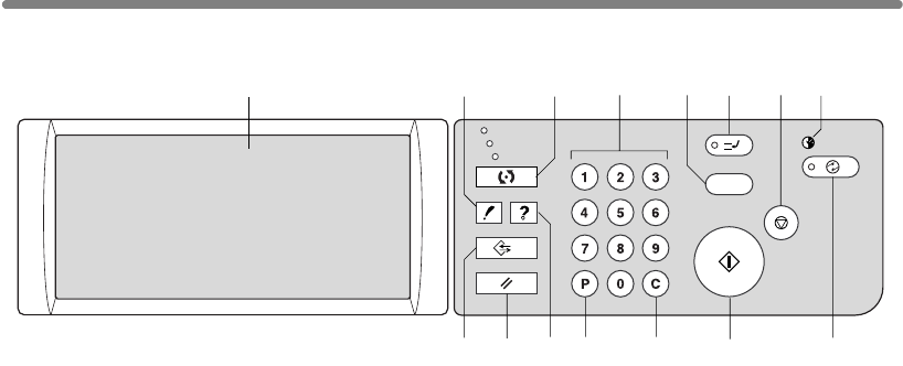
Control Panel Layout
1 LCD TOUCH SCREEN displays machine and copying status, help information,
interactive screens, and touch keys for selecting all functions.
2CHECK displays a screen showing all settings that are selected for the current job.
3MODE switches the machine operation mode to copy, scan/server, and print.
4 KEYPAD enters numeric values.
5 PROOF COPY outputs a single set of copies to confirm whether the current settings are
selected properly.
6 INTERRUPT stops copying in progress to allow copying from the platen glass.
7STOP stops the copying sequence; deletes the stored memory.
8TIMER lights when the timer function is set.
9
inactive, or activates Timer Interrupt mode when Weekly Timer function is active.
10 START activates copying or scanning.
11 [C] (CLEAR QTY.) allows resetting of print quantity.
12 [P] (COUNTER) displays the Counter Screen or accesses programming modes for
setting special functions.
13 HELP displays a screen with help for the currently selected function, or to access the
Key Operator Mode Screen.
14
15 JOB MEMORY displays screens for selecting job store/job recall functions.
CHECK
PRINT INTERRUPT
PROOF COPY
TIMER
STOP
START
JOB MEMORY
COUNTER
AUTO RESET
HELP
ON / OFF
1245678
910
3
1112131415
COPY
CLEAR QTY.
AUTO RESET restores mfp to automatic mode settings or to Key Operator settings.
SCAN
SLEEP
SLEEP ON/OFF
activates power-saving mode for times when the mfp is
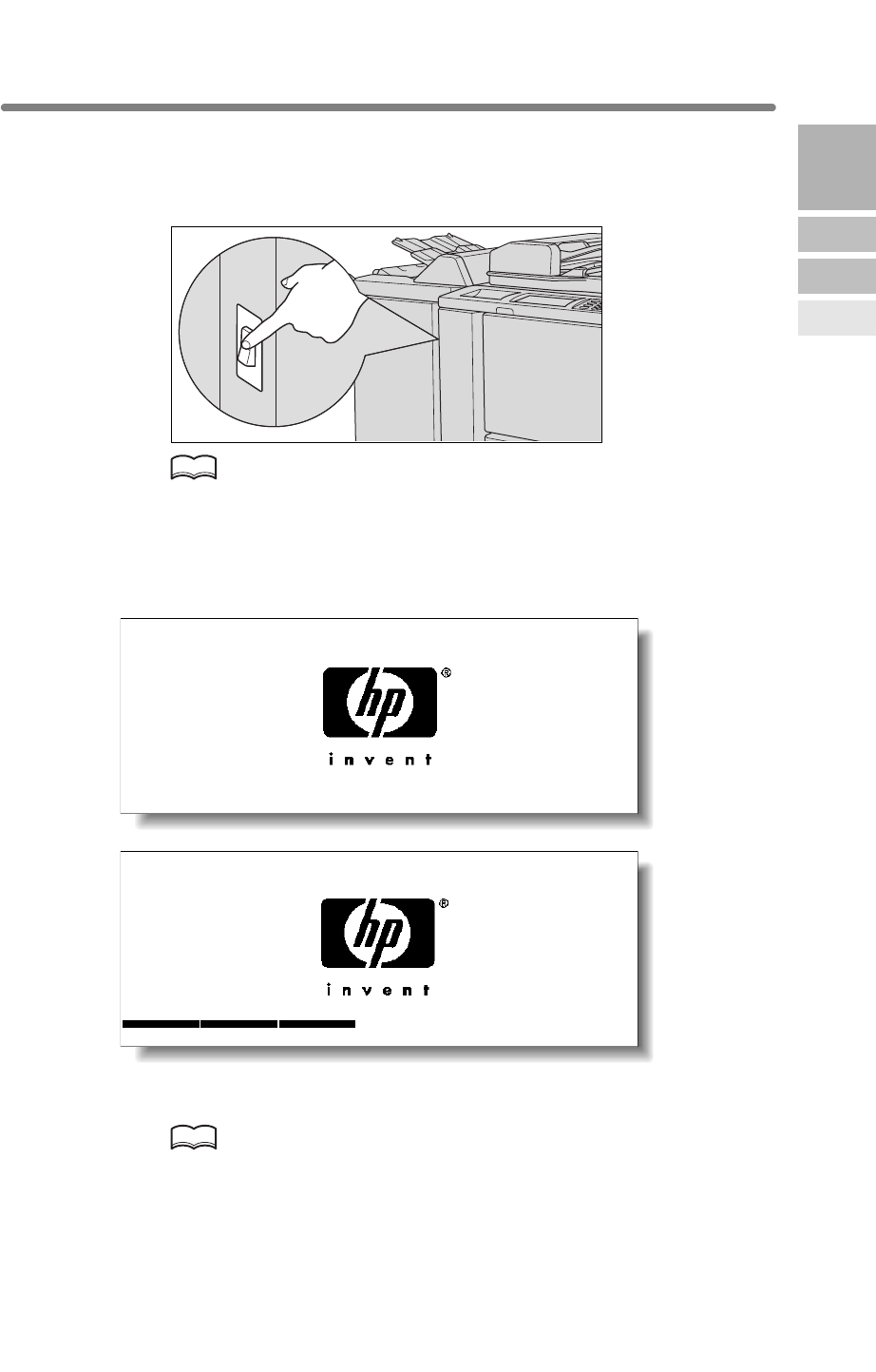
2-17
Turning On the Power Switch
To Turn On the Power
1. Turn ON the power switch.
HINT
2. The Wake-up Screen and Warm-up Screens will be displayed.
A few seconds after the Wake-up Screen appears in the LCD touch screen, seven
types of Warm-up Screens will be displayed in succession for approx. 6.0 minutes.
HINT
You can set reserve jobs while the machine is warming up. Touch the LCD
screen to change the Warm-up Screen to the Basic Screen, then check
that the message “Ready to copy reserve” is displayed on the Basic
Screen. See p. 3-8 to p. 3-9.
2
Machine
Information
Machine
Configuration
Turn On/Off
the Power
Loading
Paper
Be sure not to use the reset switch in normal operation.
The power switch is located on the left side of the engine.
If the mfp can not be turned on by the power switch, open the left door
ON. (See p. 2-4.)
of the engine, then check that the internal reset switch of the mfp is
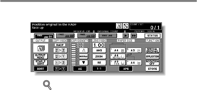
Turning On the Power Switch (continued)
2-18
3. The Basic Screen will be displayed.
The message on the Basic Screen will inform you that copying job is now available.
DETAILS
• When the initial settings are changed by the Key Operator, the modified
conditions will be displayed on the Basic Screen.
•
use the machine.
When “Enter E.C.M. password” is displayed, enter your password to
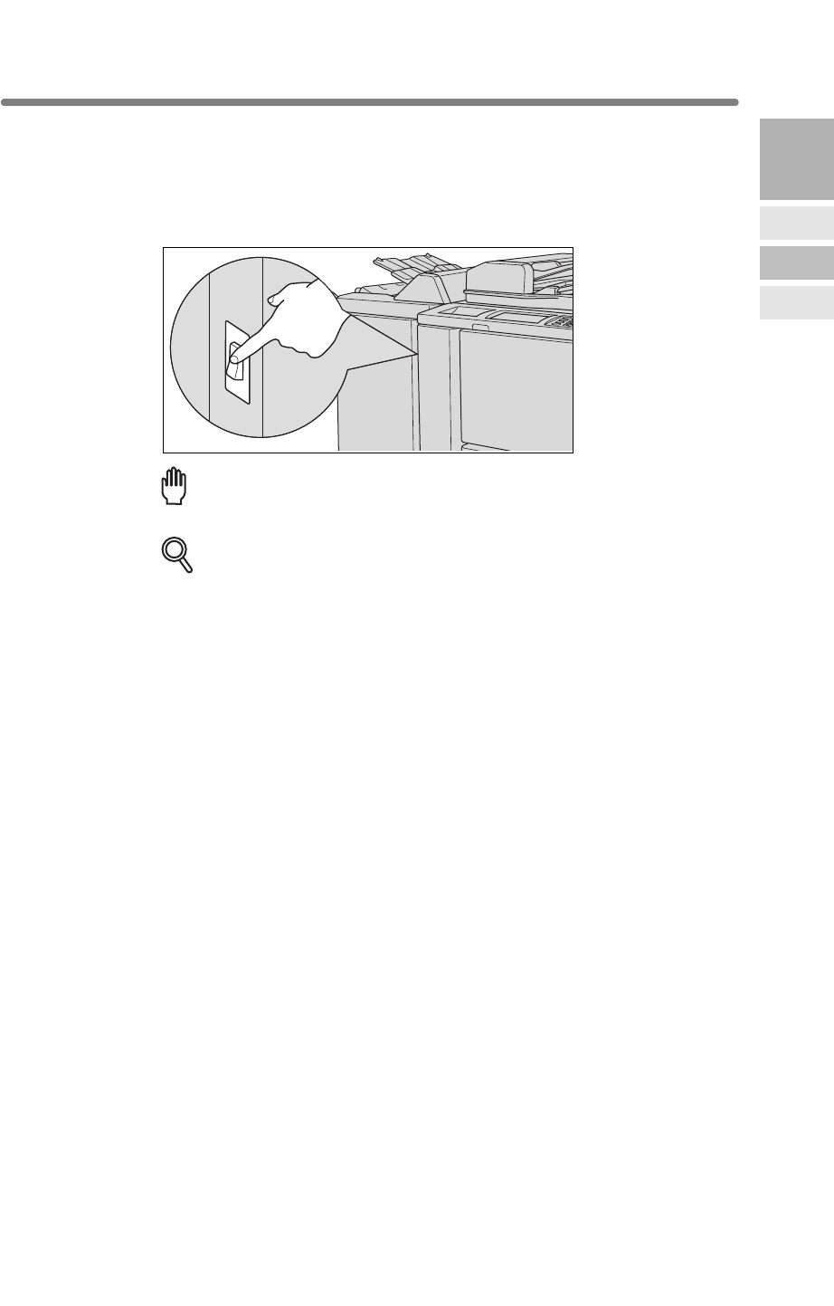
Turning On the Power Switch (continued)
2-19
To Turn Off the Power
1. Turn OFF the power switch.
The touch screen and all the LEDs on the control panel will go out.
Reminder!
DETAILS
When the machine is under control of the Weekly Timer function, turning
off the power switch will deactivate the function.
2
Machine
Information
Machine
Configuration
Turn On/Off
the Power
Loading
Paper
Be sure not to use the reset switch in normal operation.
The power switch is located on the left side of the engine.
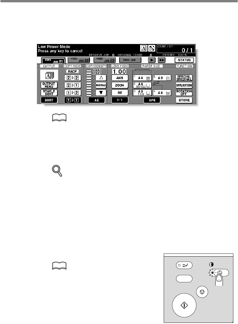
Turning On the Power Switch (continued)
2-20
Reducing the Power in Standby Mode (Auto Low Power)
This function automatically lowers the power after a specified period (initially 15
Power Mode / Press any key to cancel” displayed.
HINT
The Auto Low Power function can be set to 5 minutes/ 10 minutes/ 15
minutes/ 30 minutes/ 60 minutes/ 90 minutes/ 120 minutes/ 240 minutes
in the Key Operator mode. For the Key Operator setting, see p. 13-38.
To start a copying job, press any key on the control panel.
The Auto low power will be released and the LCD screen recovers usual brightness.
DETAILS
• If the Auto Shut-Off function activates at the same time, the power will
be turned off without the LCD screen becoming dark.
• The LCD screen will not be come dark during a duplex copying job or
when the Jam Position Screen is displayed.
Shutting Off Automatically (Auto Shut-Off)
This function automatically shuts off the power after a specified period (initially 90
The copying operation will become available.
HINTS
• The Auto shut-off can be set for 30
minutes/ 60 minutes/ 90 minutes/ 120
minutes/ 240 minutes in the Key Opera-
tor mode. For the Key Operator setting,
see p. 13-38.
• When “Timer interrupt mode / Enter
password” is displayed after pressing
and follow the procedure to continue.
INTERRUPT
PROOF COPY
TIMER
STOP
START
T
Y.
ON / OFF
minutes) of mfp inactivity. The LCD screen becomes dark with the message “Low
minutes) of mfp inactivity.
To start a copying job, press [SLEEP ON/OFF].
[SLEEP ON/OFF], see p. 7-2
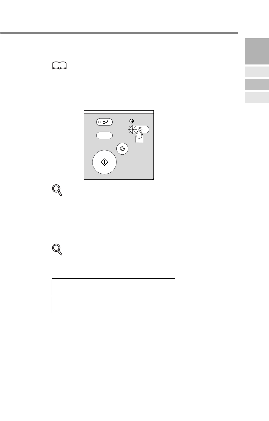
Turning On the Power Switch (continued)
2-21
Shutting Off / Reducing the Power Manually
Follow the procedure below to shut off the power manually.
HINT
The machine is initially set to activate the Manual Shut-Off function. The
Manual Low Power can be selected in the Key Operator setting. See p.
13-39 to p. 13-44.
1.
release it.
DETAILS
If Manual Low Power is selected in the Key Operator setting, the machine
2. The Shut-Off mode will be activated.
screen will be turned off.
DETAILS
otherwise the following message will be displayed and the Shut-Off (Low
Power) mode will not be activated.
then release it for shut off mode
than one second for low power mode
The machine will be available for copying operation.
INTERRUPT
PROOF COPY
TIMER
STOP
START
T
Y.
ON / OFF
2
Machine
Information
Machine
Configuration
Turn On/Off
the Power
Loading
Paper
Press [SLEEP ON/OFF] for one second or longer, then
automatically activates the Low Power mode before releasing [SLEEP
ON/OFF].
The [SLEEP ON/OFF] LED will be lit and all other LEDs and the LCD
Be sure to press [SLEEP ON/OFF] for one second or longer,
Press SLEEP more than one second,
Press SLEEP continuously more
To release the mode, press [SLEEP ON/OFF].
Turning On the Power Switch (continued)
2-22
the touch screen.
Copying will be available by following procedure:
HINT
1.
HINT
DETAILS
password.
2. Press [START].
Your current copy count and copy limit will be displayed for 3 sec.
Current count / limit
018888/025000
3. Start a copying job.
When the message changes to “Ready to copy”, copying job is available on the
machine.
DETAILS
When your copy count reaches the copy limit, the message “Copy limit
reached” will be displayed. In that case, contact the Key Operator to reset
your copy limit.
4. Press [C] while pressing [P].
displayed on the screen.
activated, a User Password is assigned, and “Enter E.C.M. password” is displayed on
Entering an ECM Password (ECM)
The Electronic Key Counter (ECM) allows the Key Operator to monitor all copying
accounts can be set.
activities by controlling ECM password accounts. Copy quantity limits for specific
The ECM is not factory-set. An ECM password is required only when the ECM is
For details of the ECM setting, see p. 13-15 to p. 13-21.
Enter ECM password.
For setting an ECM password, see p. 13-17 to p. 13-19.
If an invalid ECM password is entered, continue by entering the correct
Enter your 8-digit ECM password, using the keypad.
The initial state will be restored, with the message “Enter E.C.M. password”
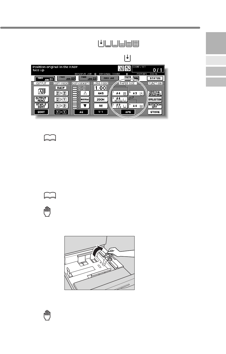
2-23
Loading Paper
A paper indicator is shown on each tray key of the Basic Screen to indicate the paper
level of the tray. (Six levels are provided: )
When paper in a tray becomes empty, the indicator “ ” appears on the tray key.
Follow the procedure below to supply the empty tray with copy paper.
HINT
When THICK or THIN is displayed on the tray key of the Basic Screen, be
sure to load the specified paper; otherwise mishandled paper may occur.
For details, see p. 13-23 to p. 13-24.
When TAB is displayed, see p. 2-28 for loading tabbed sheets.
Loading Paper in Tray 1 ,2, and 3
1. Withdraw tray 1, 2, or 3.
HINT
See p. 2-2 to check positions of each tray.
Reminder!
Do not withdraw the tray forcibly; otherwise you may be injured.
2. Open the paper feed roller.
3. Place paper on the tray with any curl turning up.
Load paper aligning it to the rear and right side of the tray.
Reminder!
Do not load above the tray hook level.
2
Machine
Information
Machine
Configuration
Turn On/Off
the Power
Loading
Paper
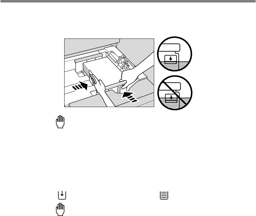
Loading Paper (continued)
2-24
4. Move the green levers (located at the front and the left side) to the
edge of the paper.
Release the release knob to lock the side guide plate.
Reminder!
• Be sure that the rear guide plate is securely aligned to the paper;
otherwise machine trouble may occur.
• Be sure that the green levers are securely aligned to the paper;
otherwise the machine cannot detect the correct paper size, or copies
may not be punched in position.
5. When paper is seated properly, close the paper feed roller.
6. Push in the tray until it locks into place.
The indicator “” on the tray key will change to “”.
Reminder!
be caused.
Do not bump the tray into the engine; otherwise machine trouble may
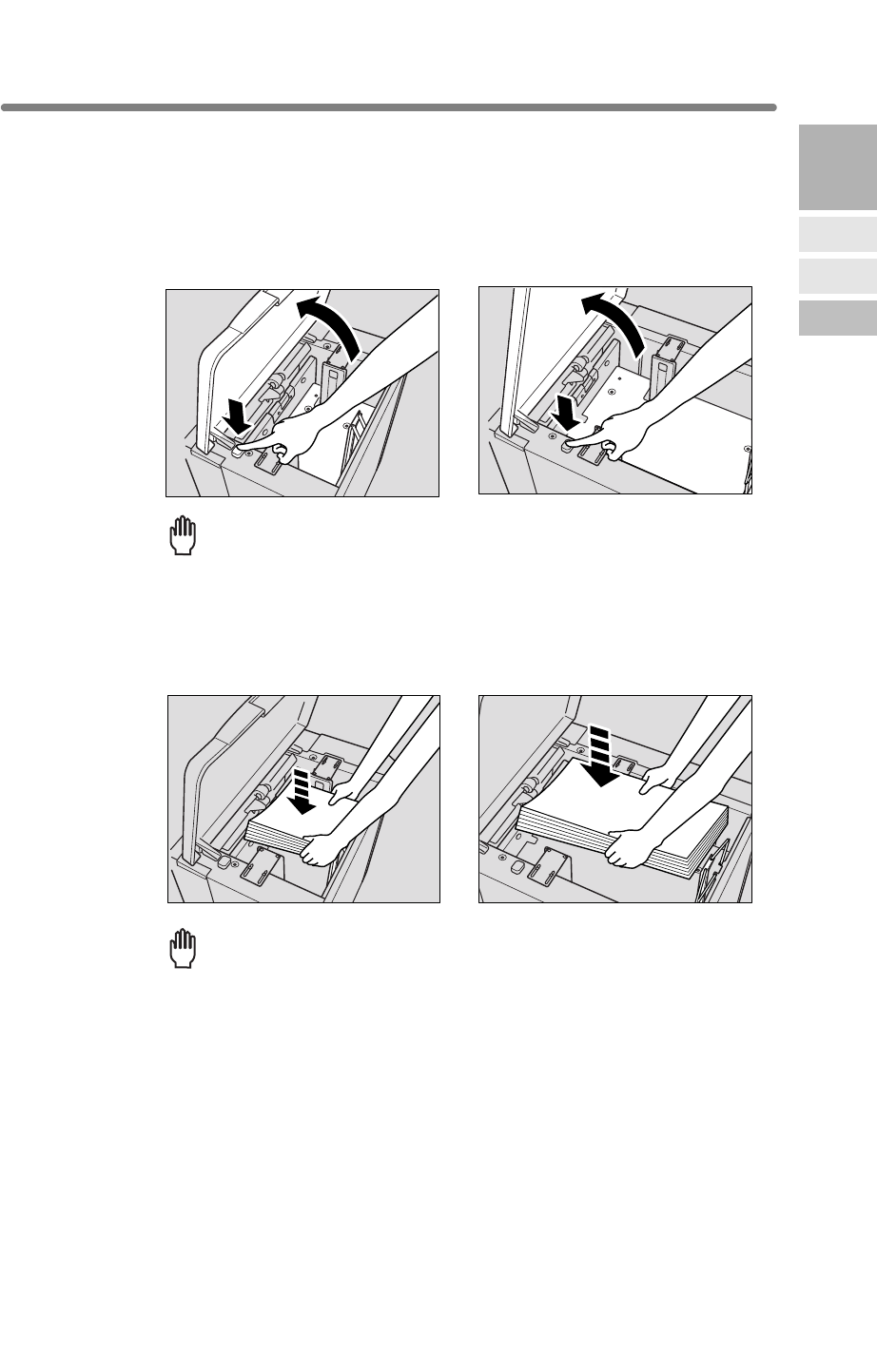
Loading Paper (continued)
2-25
1.
2.
Reminder!
Be sure that the power switch is turned on before loading paper in the
3.
making sure it is the same size as the tray has been set to.
Reminder!
2
Machine
Information
Machine
Configuration
Turn On/Off
the Power
Loading
Paper
Q3637A Q3638A
Q3637A Q3638A
Loading Paper in HCI (Q3637A/Q3638A)
Open the HCI top door.
Press the paper loading button to lower the HCI bottom plate.
Be sure to load only the paper size set for the HCI.
To change the paper size of the HCI, contact your service representative.
Load the paper into the HCI with the paper curl turning downward,
HCI. Without the power turned on, the HCI bottom plate will not function.
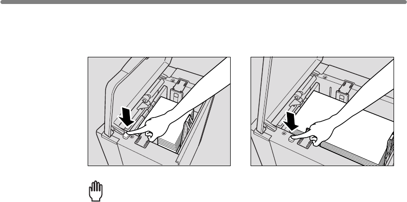
Loading Paper (continued)
2-26
4. Repeat the steps 2 and 3 until the bottom plate will not go down any
more.
Reminder!
• Do not load above the red line on the side guide plates.
• Be sure that the rear stopper is correctly positioned according to the
paper size to be loaded; otherwise machine trouble may occur.
5.
Q3637A Q3638A
Close the HCI top door.
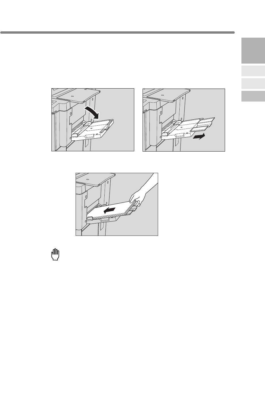
Loading Paper (continued)
2-27
Loading Paper in Multi-Sheet Bypass Tray
1. Open the Multi-sheet bypass tray located on the right side of the
When loading large paper, withdraw the right edge of the Multi-sheet bypass tray to
extend it.
2. Load copy paper, and adjust the paper guides to the paper size.
The loaded paper size will be indicated on the bypass tray key of the Basic Screen.
Reminder!
Load transparency film or thin/thick paper one sheet at a time, or stack
paper up to 150 sheets (80 g/m2 paper).
3. When copying is completed, close the Multi-sheet bypass tray.
2
Machine
Information
Machine
Configuration
Turn On/Off
the Power
Loading
Paper
mfp.
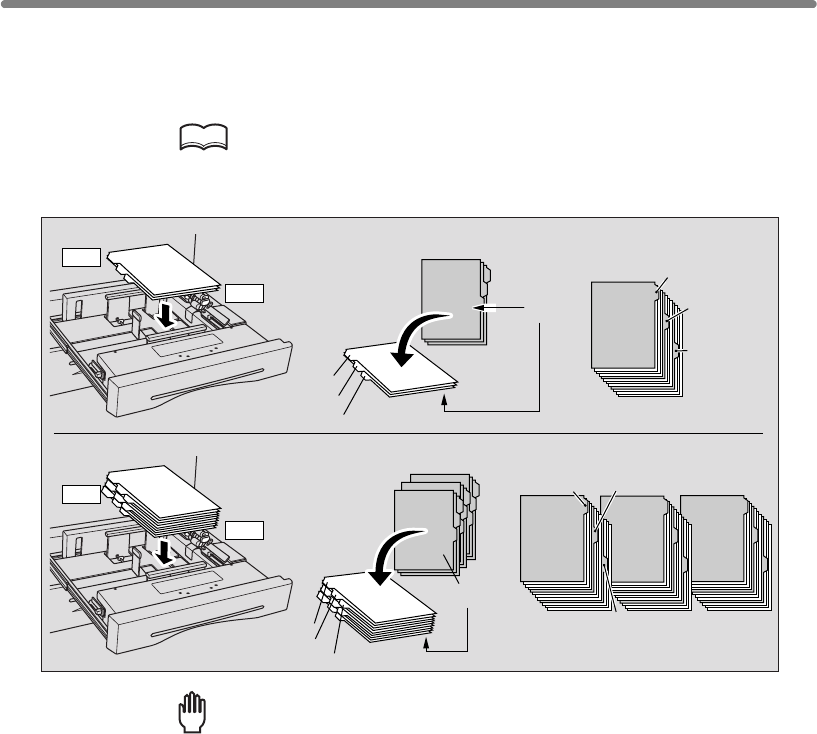
Loading Paper (continued)
2-28
Loading Tabbed Sheets in Tray 1, 2, or 3
When TAB is displayed on the tray key of the Basic Screen, follow the procedure
below to supply the tray with tabbed sheets.
HINT
The tray paper type can be specified in the Key Operator setting. For
details, see p. 13-23 to p. 13-24.
Reminder!
The tab extension width should be 12.5mm or less.
1. Withdraw tray 1, 2, or 3.
2. Open the paper feed roller.
3. Place the tabbed sheets on the tray as illustrated above.
4. Move the green levers (located at the front and the left side) to the
edge of the paper.
5. Close the paper feed roller, then push in the tray until it locks into
place.
3 FINISHED SETS
ONE FINISHED SET
Example: 9 Tabbed sheets loaded in position for 3 finished sets.
Example: 3 Tabbed sheets loaded in position for one finished set.
Section 3
Management
3rd TAB
2nd TAB
1st TAB
Printed
side
Section 1
Introduction
Section 1
Introduction
Section 1
Introduction
1st TAB 2nd TAB
3rd TAB
2nd TAB
3rd TAB
Section 1
Introduction
1st TAB
Rear
Front
Rear
Front
Section 3
Management
Section 3
Management
Section 3
Management
Printed
side
3rd TABS
2nd TABS
1st TABS
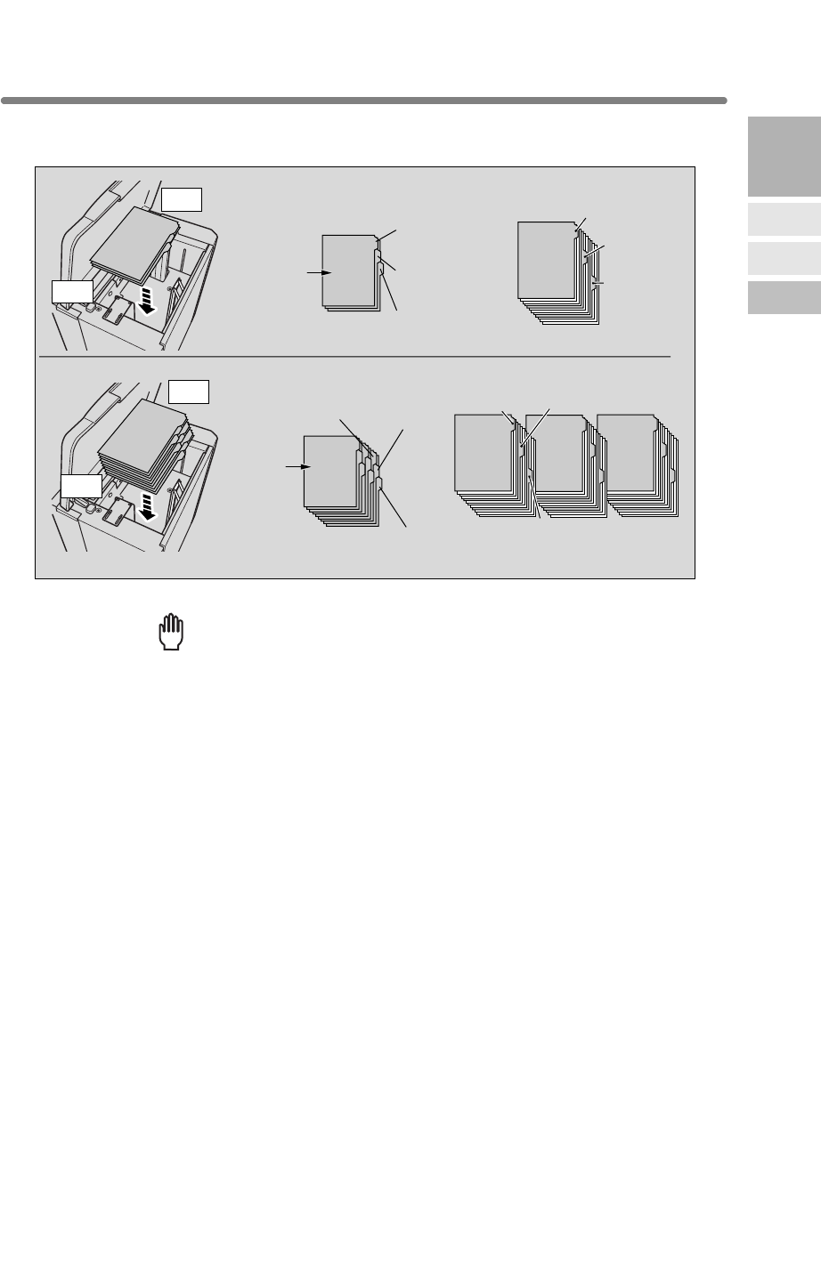
Loading Paper (continued)
2-29
2
Machine
Information
Machine
Configuration
Turn On/Off
the Power
Loading
Paper
Reminder!
• The tab extension width should be 12.5mm or less.
•
to position the rear stopper for the paper size to be loaded.
1.
2.
3.
4.
Section 1
Introduction
Section 1
Introduction
Section 1
Introduction
Section 1
Introduction
Section 1
Introduction
Section 1
Introduction
Section 1
Introduction
Section 1
Introduction
ONE FINISHED SET
THREE FINISHED SETS
Example: 3 Tabbed sheets loaded in position for one finished set.
Example: 9 Tabbed sheets loaded in position for 3 finished sets.
Printed
set
Printed
set
1st TAB
1st TAB
1st TAB
1st TAB
2nd TAB
2nd TAB
2nd TAB
2nd TAB
3rd TAB
3rd TAB
3rd TAB
3rd TAB
Rear
Front
Rear
Front
Loading Tabbed Sheets in HCI (Q3637A/Q3638A)
To load the tabbed sheets into HCI, contact your service representative
Press the paper loading button to lower the HCI bottom plate.
Load the tabbed sheets into the HCI as illustrated above.
Close the HCI top door.
Open the HCI top door.
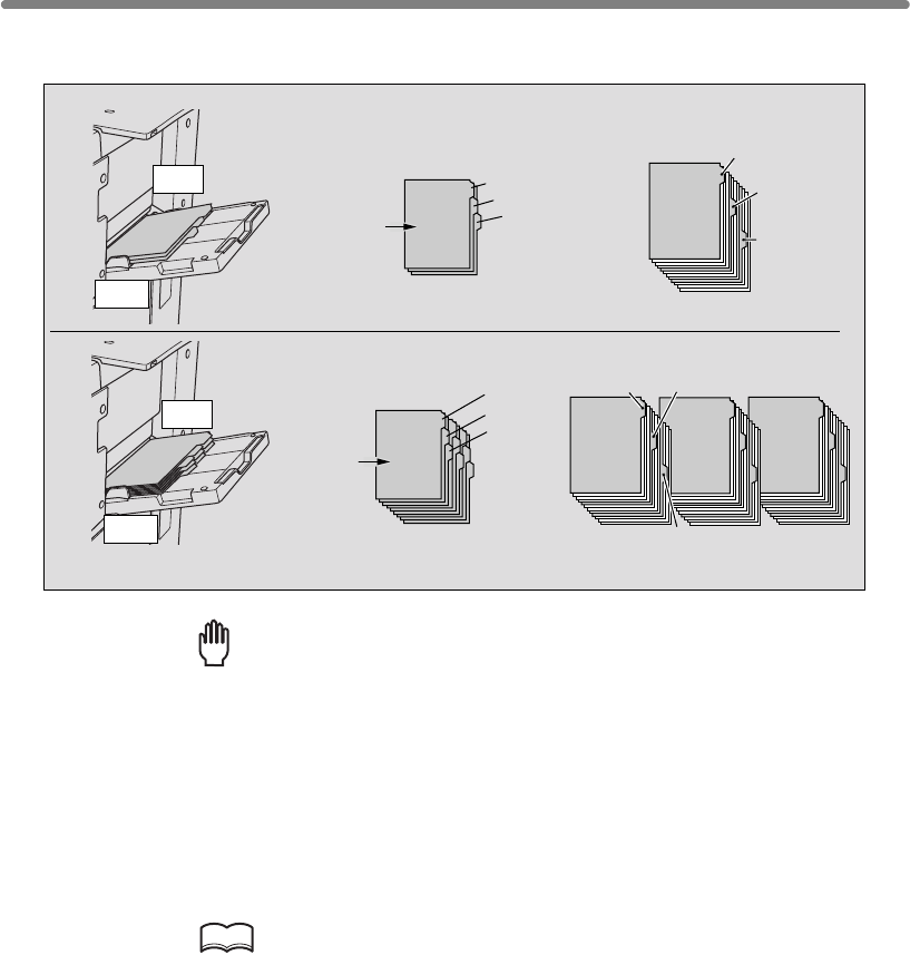
Loading Paper (continued)
2-30
Loading Tabbed Sheets in Multi-Sheet Bypass Tray
Reminder!
The tab extension width should be 12.5mm or less.
1. Open the Multi-sheet bypass tray located on the right side of the
2. Load tabbed sheets as illustrated above.
3. Adjust the paper guides to the paper size.
4. Specify the paper type as TAB for the Multi-sheet bypass tray.
HINT
See p. 3-29 to p. 3-31 for specifying the paper type of the Multi-sheet
bypass tray.
3 FINISHED SETS
ONE FINISHED SET
Example: 9 Tabbed sheets loaded in position for 3 finished sets.
Example: 3 Tabbed sheets loaded in position for one finished set.
Section 1
Introduction
3rd TAB
2nd TAB
1st TAB
Printed
side
Section 1
Introduction
Section 1
Introduction
Section 1
Introduction
1st TAB 2nd TAB
3rd TAB
2nd TAB
3rd TAB
Section 1
Introduction
1st TAB
Rear
Front
Rear
Front
Section 1
Introduction
Section 1
Introduction
Section 1
Introduction
3rd TABS
2nd TABS
1st TABS
Printed
side
mfp.

3
3
Copying
Operations
Positioning
Originals
Setting Print
Quantity
Set Job During
Warmup
Stop
Scan/Print
Paper Size
Lens Mode
Density
1-2, 2-2
2-1
Multi-Sheet
Bypass Tray
Using
Memory
Output without
Finisher
Binding
Mode
Recalling
Previous Job
Check Mode
& Proof Copy
Interrupt
Mode
Copying Operations
How to Make a Basic Copy
Positioning Originals ............................................................................... 3-2
Setting Print Quantity.......................................................................... 3-7
Setting Job During Warm-up................................................................... 3-8
To Stop Scanning/Printing ................................................................ 3-10
Selecting Paper Size..............................................................................3-11
Selecting Magnification Ratio (Lens Mode) ...................................... 3-15
Selecting Density Level......................................................................... 3-18
Copying Using Special Paper (Multi-Sheet Bypass Tray) ................ 3-29
Copying Using Memory ........................................................................ 3-32
Output Mode for Machine without Finisher....................................... 3-40
Output Mode for Machine with Finisher ................................................ 3-43
Selecting Binding Mode.................................................................... 3-48
Recalling Previous Job Settings ........................................................... 3-49
Checking Feature Selections and Proof Copying............................. 3-50
Interrupt Copying................................................................................... 3-53
Q3219A/Q3220A
Output Modes
Making Double-Sided Copies (1u2, 2u2)........................................ 3-21
Making Single-Sided Copies from Double-Sided Originals (2u1) ........ 3-27
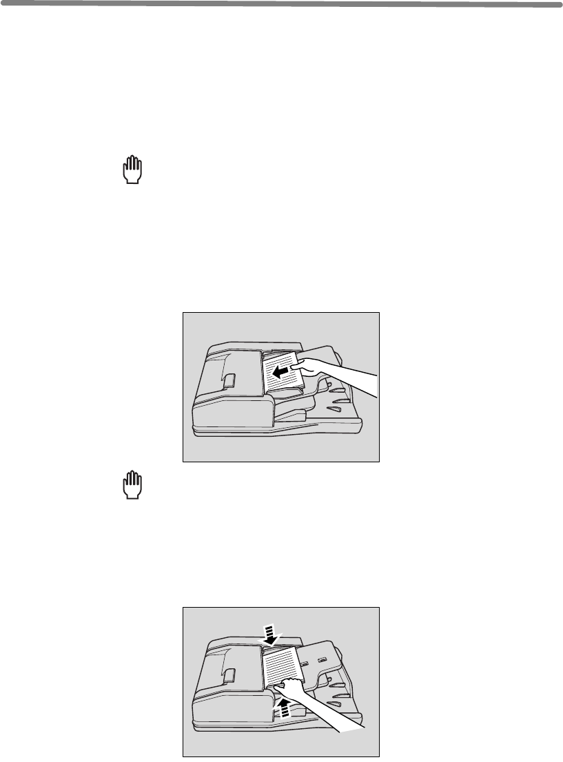
3-2
Positioning Originals
Positioning originals in Normal mode
1. Arrange originals in order.
Reminder!
• Before placing originals in the tray, be sure the document feeder is closed
selected copy conditions may be altered automatically.
•
2. Position original(s) FACE UP in the document feeder tray.
Place two-sided originals with page one FACE UP.
Up to 100 originals can be set at a time.
Reminder!
• Do not set more than 100 originals or over the red line indicated on the
paper guides; otherwise a paper misfeed will occur.
• If the number of originals exceeds 100, divide them into blocks not
exceeding 100 sheets, then load them from the block with the first page.
See p. 3-32 to p. 3-33.
3. Adjust paper guides.
smooth, flat originals.
fully. Once closed, do not open the document feeder, otherwise the
The document feeder (RADF) automatically feeds up to 100 originals directly to the
platen area, starting with the top sheet. The RADF should only be used for unstapled,
Be sure not to use unsuitable RADF originals. See p. 11-8 for details.
Positioning Originals in RADF
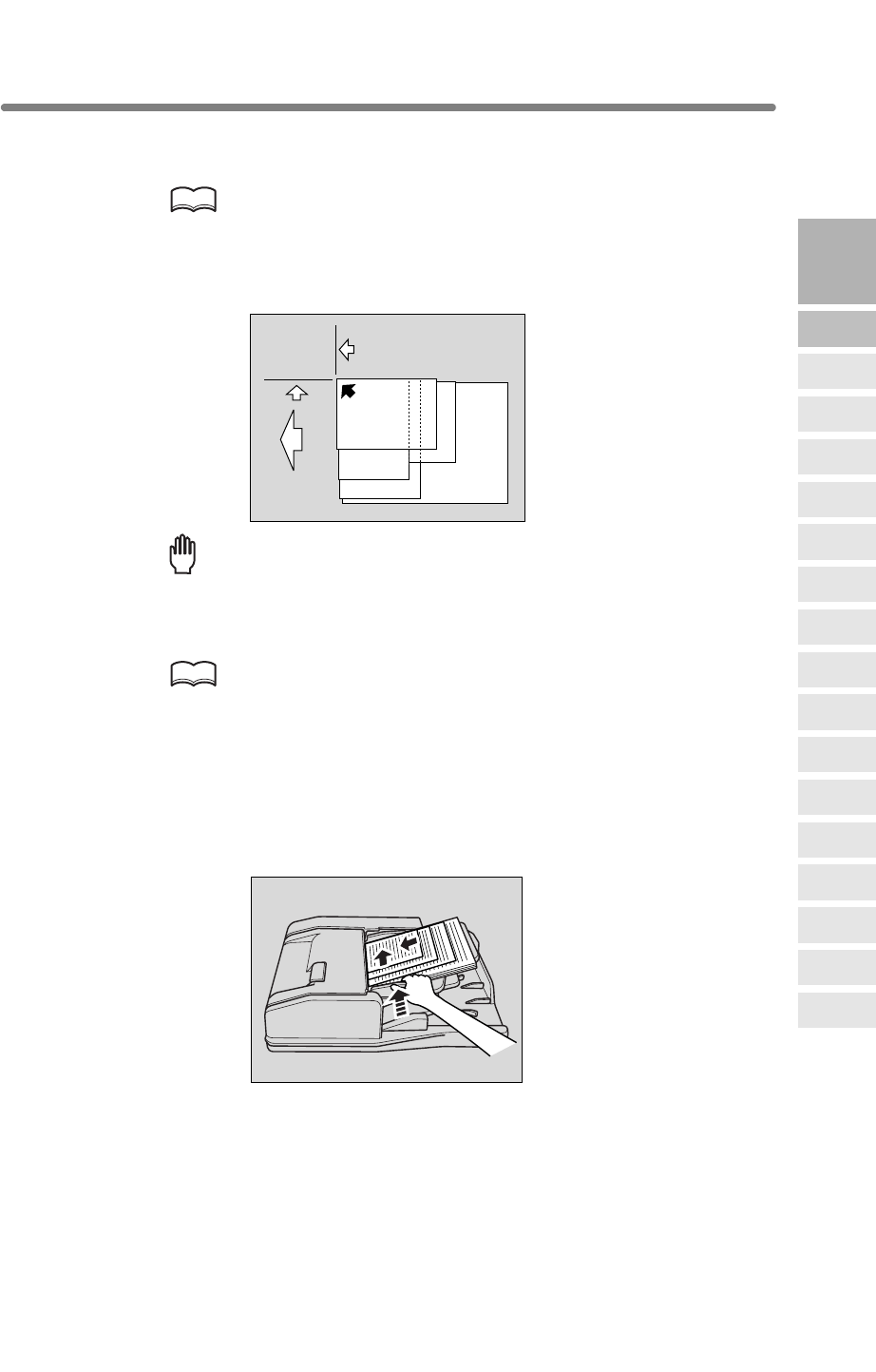
Positioning Originals (continued)
3-3
Positioning originals in Mixed original mode
Mixed size originals can be copied together from the document feeder.
HINT
To use the Mixed original mode, see procedure on p. 8-6 to p. 8-7.
1. Arrange originals in order.
Arrange the mixed size originals as illustrated below.
Reminder!
• Before placing originals in the tray, be sure the document feeder is closed
fully. Once closed, do not open the document feeder, otherwise the
selected copy conditions may be altered automatically.
•
HINT
See p. 11-9 for available combinations of mixed originals.
2. Position mixed originals FACE UP, aligned with the left rear side of the
document feeder tray.
Place two-sided originals with page one FACE UP.
Up to 100 originals can be set at a time.
3. Adjust paper guides.
Setting
direction
To the
depth
To the left
3
Copying
Operations
Positioning
Originals
Setting Print
Quantity
Set Job During
Warmup
Stop
Scan/Print
Paper Size
Lens Mode
Density
1-2, 2-2
2-1
Multi-Sheet
Bypass Tray
Using
Memory
Output without
Finisher
Binding
Mode
Recalling
Previous Job
Check Mode
& Proof Copy
Interrupt
Mode
Q3219A/Q3220A
Output Modes
Be sure not to use unsuitable RADF originals. See p. 11-8 for details.
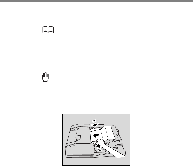
Positioning Originals (continued)
3-4
Positioning originals in Z-Folded original mode
HINT
To use the Z-Folded original mode, see procedure on p. 8-8 to p. 8-9.
1. Arrange originals in order.
2. Position original(s) FACE UP in the document feeder tray.
Place two-sided originals with page one FACE UP.
Up to 100 originals can be set at a time.
Reminder!
• Before placing originals in the tray, be sure the document feeder is closed
fully. Once closed, do not open the document feeder, otherwise the
•
3. Adjust paper guides.
Z-Folded original mode detects the folded original size without using the size detection
selected copy conditions may be altered automatically.
sensor of the RADF.
Be sure not to use unsuitable RADF originals. See p. 11-8 for details.
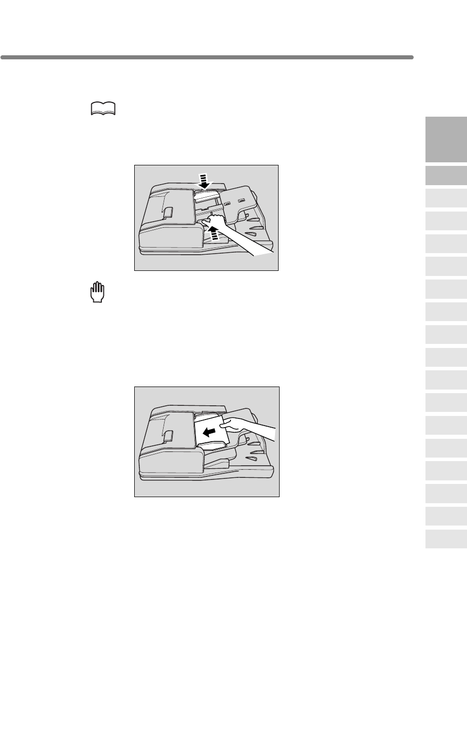
Positioning Originals (continued)
3-5
Positioning originals in SDF mode
HINT
• To use the SDF mode, see procedure on p. 8-10 to p. 8-11.
• For the SDF original specifications, see p. 11-10.
1. Adjust paper guides to the SDF original size.
Reminder!
• Before placing the SDF original in the tray, be sure the paper guides are
adjusted correctly; otherwise the SDF mode may not function properly.
•
2. Insert an original FACE UP in the document feeder tray.
Insert two-sided original with page one FACE UP.
The original will be fed and scanned automatically.
3
Copying
Operations
Positioning
Originals
Setting Print
Quantity
Set Job During
Warmup
Stop
Scan/Print
Paper Size
Lens Mode
Density
1-2, 2-2
2-1
Multi-Sheet
Bypass Tray
Using
Memory
Output without
Finisher
Binding
Mode
Recalling
Previous Job
Check Mode
& Proof Copy
Interrupt
Mode
Q3219A/Q3220A
Output Modes
In the SDF mode, one thick original can be fed through the RADF original tray.
Be sure not to use unsuitable RADF originals. See p. 11-8 for details.
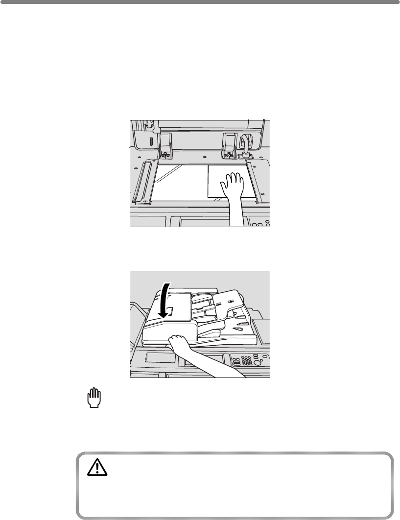
Positioning Originals (continued)
3-6
Positioning Original on Platen Glass
Use the platen glass when originals are not suitable for use with the document feeder,
e.g., when size is incompatible, or when originals are folded, stapled, torn, or in
generally poor condition.
1. Raise the document feeder.
Place original FACE DOWN in the right rear corner, aligning the edge with the right
measuring guide.
2.
Reminder!
CAUTION
Do not place too heavy originals, or do not press strongly when
thick original is placed and is under pressure of RADF;
otherwise the glass may be broken and you may be injured.
Gently close the document feeder to prevent the original from shifting
on the glass.
When selecting Dual Page, Non-Image Area Erase, AUTO mode in Repeat,
or AUTO Layout, DO NOT CLOSE the document feeder. For details on each
function, see Section 9.
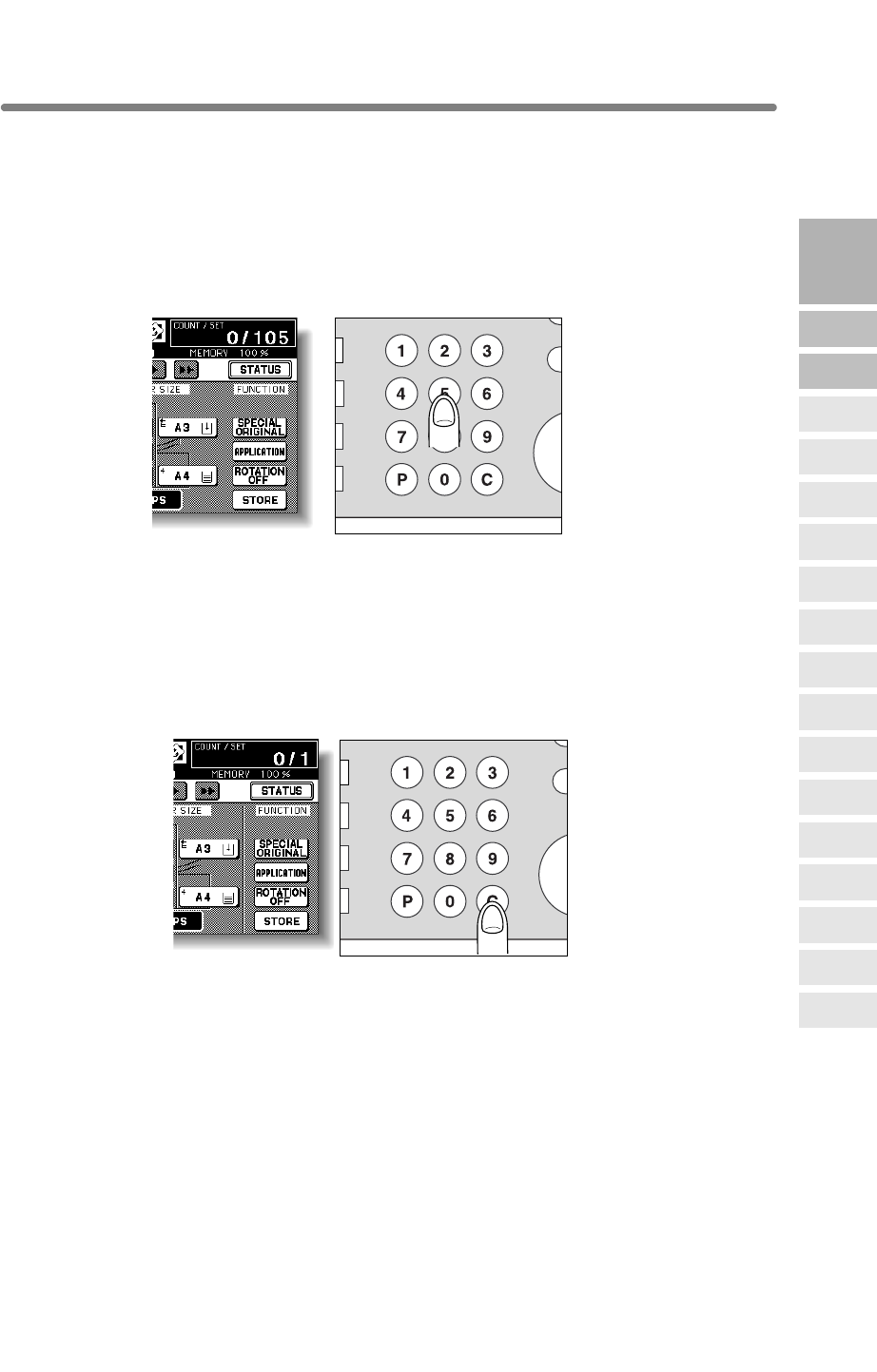
3-7
Setting Print Quantity
This section describes how to set or change print quantity.
To Set Print Quantity
quantity setting, then outputs sorted sets.
1. Enter the desired print quantity from the control panel keypad.
Entered quantity will be displayed on the touch panel.
To Change Print Quantity
Follow the procedure below to change the print quantity that has been already entered.
1. Press [C (CLEAR QTY.)].
The quantity displayed on the touch panel will return to 1.
2. Enter the correct quantity.
Entered quantity will be displayed on the touch panel.
IN
T
PR
O
S
Y
CLEAR QTY.
COUNTER
P
IN
T
PR
O
S
Y
CLEAR QTY.
COUNTER
P
3
Copying
Operations
Positioning
Originals
Setting Print
Quantity
Set Job During
Warmup
Stop
Scan/Print
Paper Size
Lens Mode
Density
1-2, 2-2
2-1
Multi-Sheet
Bypass Tray
Using
Memory
Output without
Finisher
Binding
Mode
Recalling
Previous Job
Check Mode
& Proof Copy
Interrupt
Mode
Q3219A/Q3220A
Output Modes
The mfp is initially set to copy the original set in amounts determined by the print
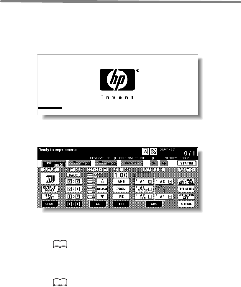
3-8
Setting Job During Warm-up
1. Turn on the power switch of the machine.
A few seconds after the Wake-up Screen appears in the LCD touch panel, seven types
of Warm-up Screen display in succession for approx. 6 minutes.
2. Touch the LCD panel to change the Warm-up Screen to the Basic
Screen.
Check that the message “Ready to copy reserve” is displayed on the Basic Screen.
3. Set the desired copying conditions, and enter the print quantity.
HINT
See p. 3-7 for details on setting print quantity.
4.
HINT
See p. 3-2 to p. 3-6 for details on positioning originals.
5. Press [START].
The original for the job will be scanned.
platen glass.
Position original(s) FACE UP in the RADF or FACE DOWN on the
While the mfp is warming up after power is turned on, select copy conditions and start
scanning so that the mfp may start printing immediately the mfp engine is ready.
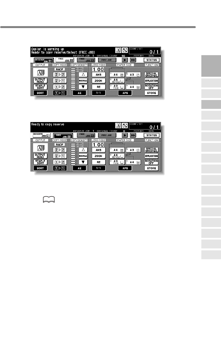
Setting Job During Warm-up (continued)
3-9
When scanning is completed, the highlighted FREE JOB folder key will change to
RESERVE JOB, and the next FREE JOB becomes active.
6. If setting more than one reserve job, touch the next FREE JOB to
highlight it.
Repeat step 3 to 5. Up to 10 reserve jobs can be prepared. If all four reserve job keys
are used, touch the arrow keys at the right side of the folder keys to scroll.
Copying on the reserve job will start automatically after completing the warm-up.
HINTS
• To stop printing, press [STOP]. See p. 3-10 for details.
• The Job Status Screen allows you to alter the output order of the reserve
jobs or to delete the reserve job. See p. 3-37 ~ p. 3-38.
3
Copying
Operations
Positioning
Originals
Setting Print
Quantity
Set Job During
Warmup
Stop
Scan/Print
Paper Size
Lens Mode
Density
1-2, 2-2
2-1
Multi-Sheet
Bypass Tray
Using
Memory
Output without
Finisher
Binding
Mode
Recalling
Previous Job
Check Mode
& Proof Copy
Interrupt
Mode
Q3219A/Q3220A
Output Modes
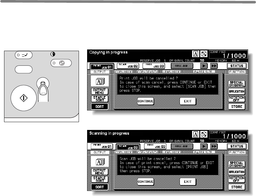
3-10
To Stop Scanning/Printing
Follow the procedure below to stop scanning or printing.
1. Touch to highlight SCAN JOB or PRINT JOB to be suspended.
2. Press [STOP].
The current machine operation of the selected job will be suspended, and the popup
menu will display on the Basic Screen to ask you to continue or cancel the job.
3. Touch EXIT to cancel the job and delete the data, or CONTINUE to
complete the job.
INTERRUPT
PROOF COPY
TIMER
STOP
START
ON / OFF
SLEEP
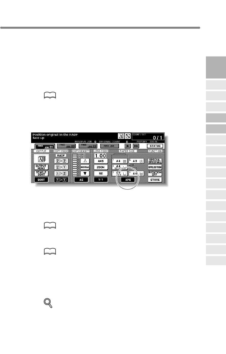
3-11
Selecting Paper Size
To select an appropriate paper size for getting your desired copy result, use APS
(Automatic Paper Selection), or select paper size manually on the touch screen, as
required.
To Select Paper Size Automatically (APS)
HINTS
• See the table on the following page for the relation of original size,
magnification ratio and copy paper size.
• The initial settings may have been altered by Key Operator. See p. 13-10
to p. 13-11.
1. Touch to highlight APS at lower right corner of the Basic Screen.
APS is already highlighted when the initial settings are restored.
2. Select additional copy conditions, as desired.
3. Enter the desired print quantity from the control panel keypad.
HINT
See p. 3-7 for details on setting print quantity.
4. Position original(s).
HINTS
•
the platen glass.
• See p. 3-2 to p. 3-6 for details on positioning originals.
•
the platen glass. See p. 13-39 to p. 13-44.
5. Press [START].
Scanned image will be printed on the paper size automatically selected.
DETAILS
• If the appropriate copy paper is not loaded in any tray, no copying will be
performed, and a message will prompt you to load the appropriate paper.
• Copy result may not be satisfactory due to the Rotation function. In this
case, turn the function OFF manually. See. p. 7-4.
3
Copying
Operations
Positioning
Originals
Setting Print
Quantity
Set Job During
Warmup
Stop
Scan/Print
Paper Size
Lens Mode
Density
1-2, 2-2
2-1
Multi-Sheet
Bypass Tray
Using
Memory
Output without
Finisher
Binding
Mode
Recalling
Previous Job
Check Mode
& Proof Copy
Interrupt
Mode
selects and feeds copy paper of the same size, or selects an appropriate size according
to the magnification ratio selected.
Q3219A/Q3220A
Output Modes
APS detects the size of originals placed on the RADF or platen glass and automatically
See p. 11-8 to p. 11-10 for paper sizes detectable from the RADF or on
Key Operator can deactivate APS when original is set in the RADF or on
Selecting Paper Size (continued)
3-12
See the table below for the relation of original size, magnification ratio and
copy paper size.
Original size
A3 B4 F4
F4
A4 B5A4R B5R A5 A5R
Paper size Paper size
B5R
A4R
B4
B4
A5R
A5R
B6R B6R
A3
B5R
A4R
B4
A3 A3
0.25 - 0.42
0.43 - 0.50
0.51 - 0.55
0.56 - 0.57
0.58 - 0.61
0.62 - 0.64
0.65 - 0.71
0.72 - 0.78
0.79 - 0.82
0.83 - 0.86
0.87 - 0.90
0.91 - 1.00
1.01 - 1.10
1.11 - 1.15
1.16 - 1.22
1.23 - 1.41
1.42 - 1.73
1.74 - 4.00
0.25 - 0.42
0.43 - 0.50
0.51 - 0.55
0.56 - 0.57
0.58 - 0.61
0.62 - 0.64
0.65 - 0.71
0.72 - 0.78
0.79 - 0.82
0.83 - 0.86
0.87 - 0.90
0.91 - 1.00
1.01 - 1.10
1.11 - 1.15
1.16 - 1.22
1.23 - 1.41
1.42 - 1.73
1.74 - 4.00
B6R
B6R
A5R
B5R
A4R
A5
A5
B6R
A4
A3
B5
B5
B6R
A5R
A4R
B5R
A4
A5R
B6R
B6R
B6R
A5R
B5R
A4R
B4
A3
A5
B5
A4
A3
B5R
A4R
B4
A3
A3
B4
A3
Magnification ratio
Magnification ratio
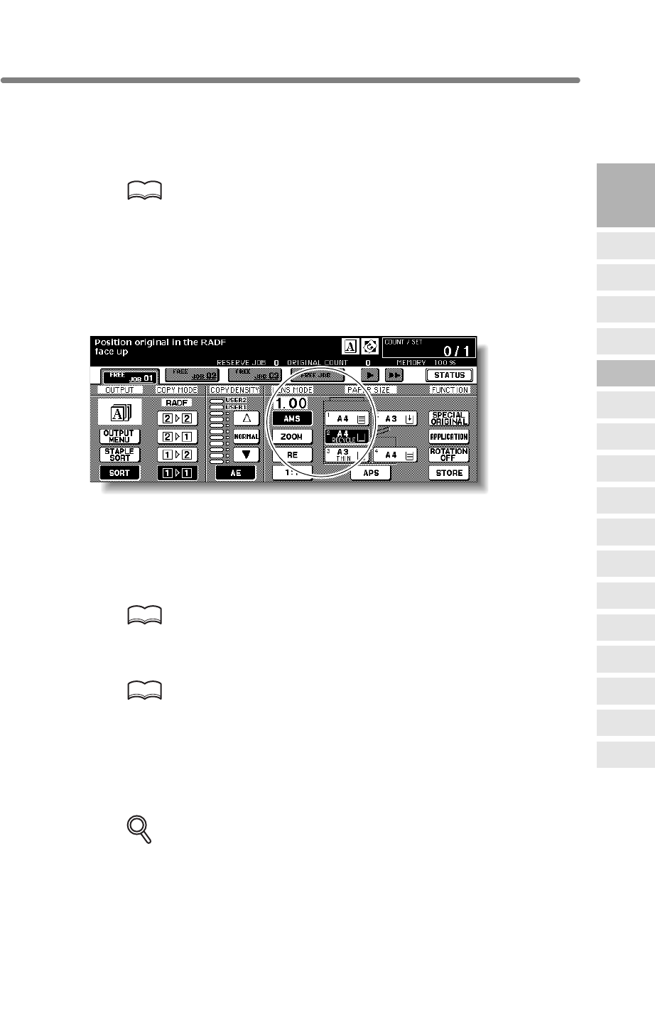
Selecting Paper Size (continued)
3-13
To Specify Desired Paper Size (AMS)
HINTS
• See the table on the following page for the relation of original size, copy
paper size, and magnification ratio automatically selected.
• Wide paper size can be specified when AMS is in use.
In this case, the same magnification ratio as that of the standard size will
be selected automatically.
• If copying in 1.00 (100%) magnification mode and specifying a paper
size, see p. 3-15.
1. Touch a tray key on the Basic Screen to select the desired paper size.
Selected tray key will be highlighted, and under the LENS MODE AMS indication will
also be highlighted.
2. Select additional copy conditions, as desired.
3. Enter the desired print quantity from the control panel keypad.
HINT
See p. 3-7 for details on setting print quantity.
4. Position original(s).
HINTS
•
the platen glass.
See p. 3-2 to p. 3-6 for details on positioning originals.
5. Press [START].
Scanned image will be printed on the specified paper size using an automatically
selected magnification ratio.
DETAILS
Copy result may not be satisfactory due to the Rotation function. In this
case, turn the function OFF manually. See. p. 7-4.
3
Copying
Operations
Positioning
Originals
Setting Print
Quantity
Set Job During
Warmup
Stop
Scan/Print
Paper Size
Lens Mode
Density
1-2, 2-2
2-1
Multi-Sheet
Bypass Tray
Using
Memory
Output without
Finisher
Binding
Mode
Recalling
Previous Job
Check Mode
& Proof Copy
Interrupt
Mode
•
When a paper size is specified on the touch screen, an appropriate reduction or
enlargement ratio will be selected automatically according to the original size detected
Q3219A/Q3220A
Output Modes
from the RADF or the platen glass.
See p. 11-8 to p. 11-10 for paper sizes detectable from the RADF or on
Selecting Paper Size (continued)
3-14
See the table below for the relation of original size, copy paper size, and
magnification ratio automatically selected.
A3
B4R
A4
A4R
B5
B5R
A5
A5R
A3 B4 F4 A4 A4R B5 B5R A5 A5R
1.00 1.15 1.27 1.00 1.41 1.15 1.63 1.41 2.00
0.86 1.00 1.10 0.86 1.22 1.00 1.41 1.22 1.73
0.50 0.58 0.64 1.00 0.71 1.15 0.82 1.41 1.00
0.71 0.82 0.90 0.71 1.00 0.82 1.15 1.00 1.41
0.43 0.50 0.55 0.86 0.61 1.00 0.71 1.22 0.86
0.61 0.71 0.78 0.61 0.86 0.71 1.00 0.86 1.22
0.35 0.41 0.45 0.71 0.50 0.81 0.58 1.00 0.71
0.50 0.58 0.64 0.50 0.71 0.58 0.81 0.71 1.00
Original size
Paper size
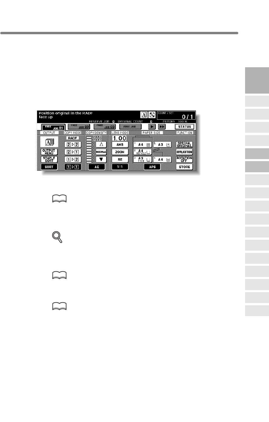
3-15
Selecting Magnification Ratio (Lens Mode)
on the Basic Screen.
Follow each procedure described in this section to select the desired magnification
ratio.
To Copy in 1.00 Magnification Mode
Follow this procedure to make a 100% copy of the original image.
1.
The initial settings are restored. Check that APS is highlighted to indicate that the 1.00
magnification is selected.
HINT
The initial settings may be altered by the Key Operator. See p. 13-10 to p.
13-11.
2. Select additional copy conditions, as desired.
DETAILS
Specifying paper size will release 1.00 magnification and set
AMS
automatically.
In this case, touch
1:1
to highlight it again.
3. Enter the desired print quantity from the control panel keypad.
HINT
See p. 3-7 for details on setting print quantity.
4. Position original(s).
HINT
See p. 3-2 to p. 3-6 for details on positioning originals.
5. Press [START].
3
Copying
Operations
Positioning
Originals
Setting Print
Quantity
Set Job During
Warmup
Stop
Scan/Print
Paper Size
Lens Mode
Density
1-2, 2-2
2-1
Multi-Sheet
Bypass Tray
Using
Memory
Output without
Finisher
Binding
Mode
Recalling
Previous Job
Check Mode
& Proof Copy
Interrupt
Mode
Q3219A/Q3220A
Output Modes
Close the RADF securely, then press [AUTO RESET].
When the mfp is turned ON, the magnification ratio is set to 1.00 (100%) automatically
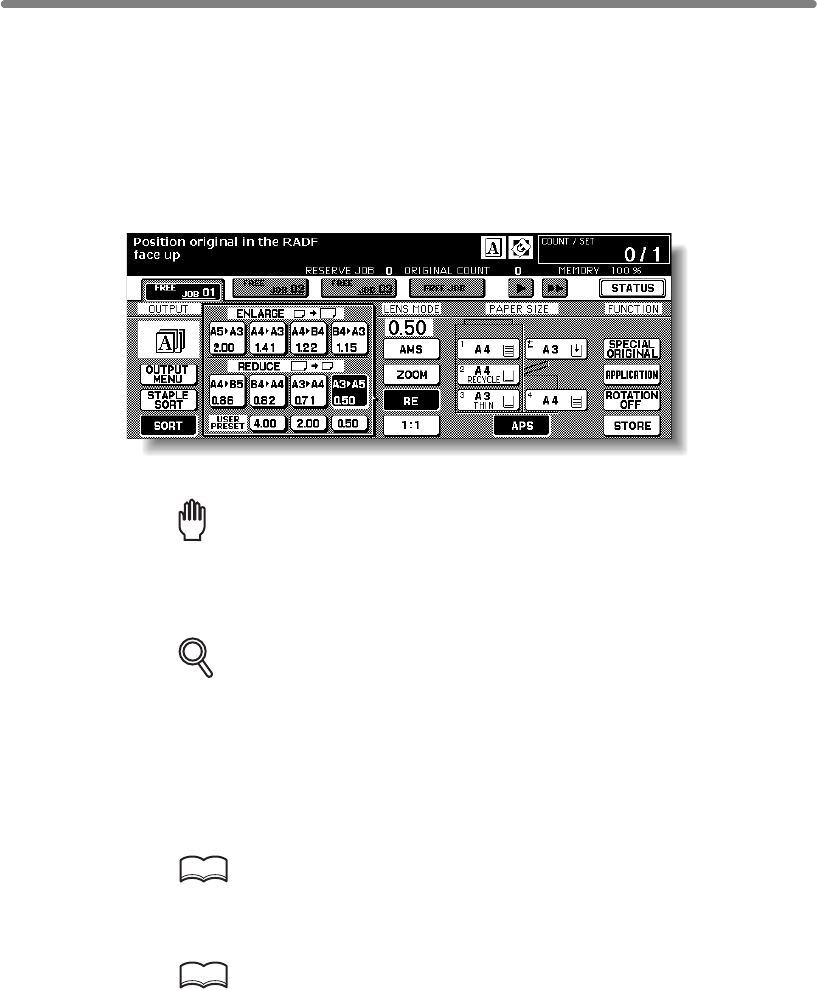
Selecting Magnification Ratio (Lens Mode) (continued)
3-16
To Copy in Fixed Magnification Mode (RE)
Use the 8 preset ratios (0.50, 0.71, 0.82, 0.86, 1.15, 1.22, 1.41, 2.00) and 3 user preset
ratios to increase or decrease magnification in fixed amounts.
>>> Specification for Fixed Magnification Mode <<<
Incompatible Conditions: AMS, Repeat mode in Repeat, Reduce & Shift in Image Shift
1. Touch RE on the Basic Screen.
The popup menu for selecting the desired preset/user preset ratio will be displayed.
Reminder!
press [AUTO RESET].
2. Select the desired magnification.
DETAILS
Touching any key on the popup menu will momentarily highlight that key,
then the popup menu will disappear automatically.
The selected ratio will be displayed on the Basic Screen.
Three user preset ratios are adjustable by the Key Operator. See p. 13-14.
3. Select additional copy conditions, as desired.
4. Enter the desired print quantity from the control panel keypad.
HINT
See p. 3-7 for details on setting print quantity.
5. Position original(s).
HINT
See p. 3-2 to p. 3-6 for details on positioning originals.
6. Press [START].
When starting a new copying job, be sure to close the RADF securely, then
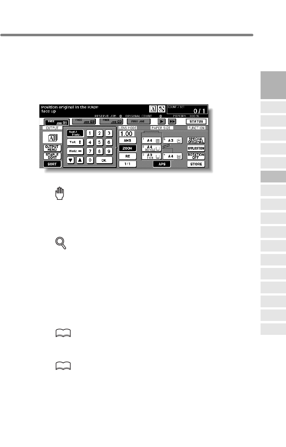
Selecting Magnification Ratio (Lens Mode) (continued)
3-17
To Copy in Zoom Mode
Use the Zoom mode to reduce or enlarge the copied original image in 1% increments.
>>> Specification for Zoom Mode <<<
Zoom range: 0.25 ~ 4.00
Incompatible Conditions: AMS, Repeat mode in Repeat, Reduce & Shift in Image Shift
1. Touch ZOOM on the Basic Screen.
The popup menu for setting a zoom ratio will be displayed.
Reminder!
press [AUTO RESET].
2. Touch Vert./Horiz. on the popup menu, if not highlighted, then set the
desired zoom ratio.
DETAILS
3. Touch OK.
The popup menu disappears automatically and the specified zoom ratio will be
4. Select additional copy conditions, as desired.
5. Enter the desired print quantity from the control panel keypad.
HINT
See p. 3-7 for details on setting print quantity.
6. Position original(s).
HINT
See p. 3-2 to p. 3-6 for details on positioning originals.
7. Press [START].
3
Copying
Operations
Positioning
Originals
Setting Print
Quantity
Set Job During
Warmup
Stop
Scan/Print
Paper Size
Lens Mode
Density
1-2, 2-2
2-1
Multi-Sheet
Bypass Tray
Using
Memory
Output without
Finisher
Binding
Mode
Recalling
Previous Job
Check Mode
& Proof Copy
Interrupt
Mode
Q3219AQ3220A
Output Modes
When starting a new copying job, be sure to close the RADF securely, then
If an incorrect ratio is entered, continue by entering the correct 3-digit ratio.
Use the keypad on the popup menu to enter the desired magnification ratio
displayed on the Basic Screen.
in 3 digits, or use arrows ( p/q ) to scroll to the desired ratio.
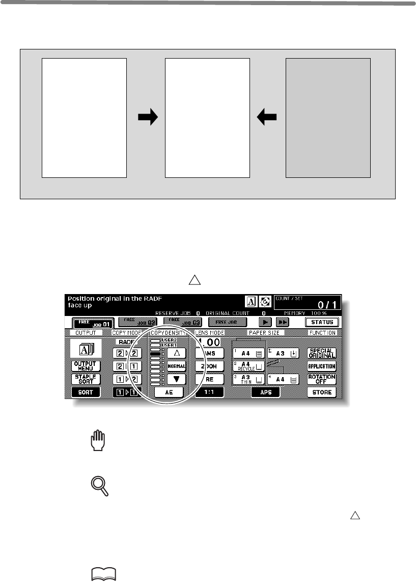
3-18
Selecting Density Level
Automatic Exposure (AE) operates with the default settings. It detects the density of the
original image and automatically selects the appropriate exposure for the copy.
To Select Copy Density
Select manual copy density to adjust exposure (density) when originals are too light or
too dark. Manual adjustments can be made in 9 levels on the Basic Screen.
1.
Highlight the desired exposure level indicator.
Reminder!
press [AUTO RESET].
DETAILS
• Touch NORMAL to select the middle density level.
• To select the user-set density (USER1 or USER2), touch to highlight
the desired indicator.
• When resuming AE, touch AE.
2. Select additional copy conditions, as desired.
HINT
See p. 13-12 to p. 13-13 to set the user-set density.
Light original Normal Dark original
ABCD
EFGH
IJKLM
NOPQ
RSTUV
WXYZ
ABCD
EFGH
IJKLM
NOPQ
RSTUV
WXYZ
ABCD
EFGH
IJKLM
NOPQ
RSTUV
WXYZ
When starting a new copying job, be sure to close the RADF securely, then
Touch q to darken, or touch to lighten the copy image.

Selecting Density Level (continued)
3-19
3. Enter the desired print quantity from the control panel keypad.
HINT
See p. 3-7 for details on setting print quantity.
4. Position original(s).
HINT
See p. 3-2 to p. 3-6 for details on positioning originals.
5. Press [START].
3
Copying
Operations
Positioning
Originals
Setting Print
Quantity
Set Job During
Warmup
Stop
Scan/Print
Paper Size
Lens Mode
Density
1-2, 2-2
2-1
Multi-Sheet
Bypass Tray
Using
Memory
Output without
Finisher
Binding
Mode
Recalling
Previous Job
Check Mode
& Proof Copy
Interrupt
Mode
Q3219A/Q3220A
Output Modes
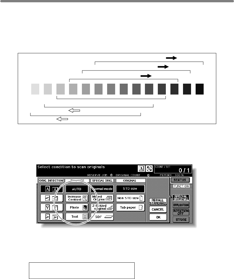
Selecting Density Level (continued)
3-20
Density Shift
Use this function to shift each of nine density levels to three levels lighter or three levels
darker.
This function can be set to use in combination with AUTO (Text/Photo), Text, Photo and
Increase Contrast modes and the general mode.
1. Touch SPECIAL ORIGINAL on the Basic Screen.
The Special Original popup menu will be displayed.
2. Select the desired mode.
(eg.) To set the Text mode, touch Text to highlight it.
3. Press [P (COUNTER)].
The following message will be displayed.
Density Shift (Text)
2 (0 ~ 5)
4. Press any key (from 0 to 5) using the keypad to determine the Density
shift.
Entering 6 or above will be ignored.
5. Touch OK on the Special Original popup menu.
Density shift in the selected enhance mode is determined.
Density shift 3
Density shift 2
Density shift 1
Density shift 0
Density shift 4
Density shift 5
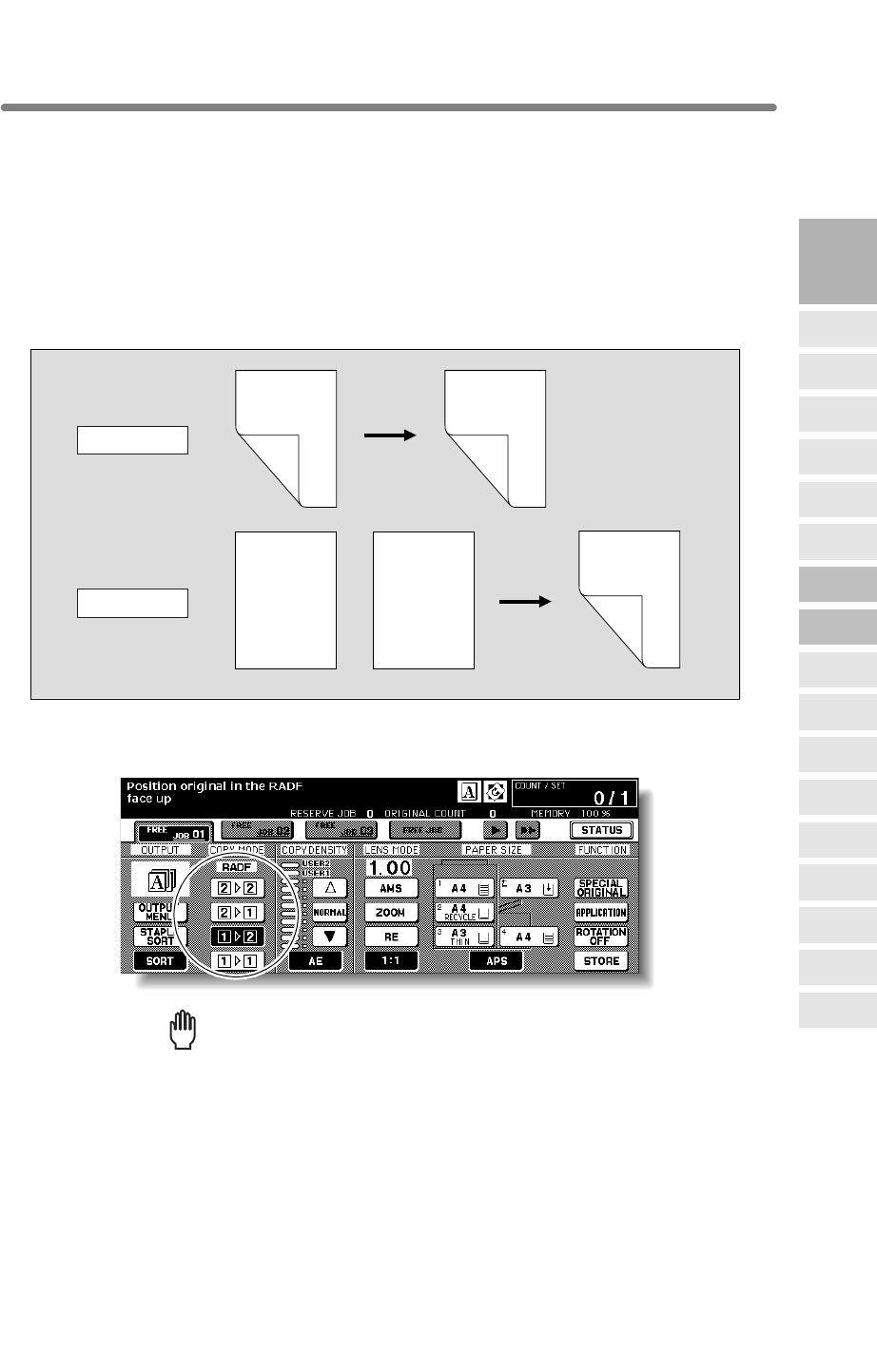
3-21
single-sided originals.
Follow the procedure below to make double-sided copies from the originals scanned
from the document feeder or from the platen glass.
Select the copy mode according to the original type (single-sided or double-sided).
1.
Reminder!
press [AUTO RESET].
Double-sided original Duplex copy
Duplex copy
Single-sided original
2-2 Copying
1-2 Copying
Front
Front
Front
Front
Front
Back
Back
Back
Back
Back
Front
Front
Front
Front
Front
Back
Back
Back
Front
Front
Front
Front
Front
Back
Back
Back
Front
Front
Front
Front
Front
Back
Back
Back
3
Copying
Operations
Positioning
Originals
Setting Print
Quantity
Set Job During
Warmup
Stop
Scan/Print
Paper Size
Lens Mode
Density
1-2, 2-2
2-1
Multi-Sheet
Bypass Tray
Using
Memory
Output without
Finisher
Binding
Mode
Recalling
Previous Job
Check Mode
& Proof Copy
Interrupt
Mode
Q3219A/Q3220A
Output Modes
Using RADF
When starting a new copying job, be sure to close the RADF securely, then
The Basic Screen is initially set to 1u1 copy mode to make single-sided copies from
Touch 1u2 or 2u2 on the Basic Screen to highlight it.
Making Double-Sided Copies (1u2, 2u2)
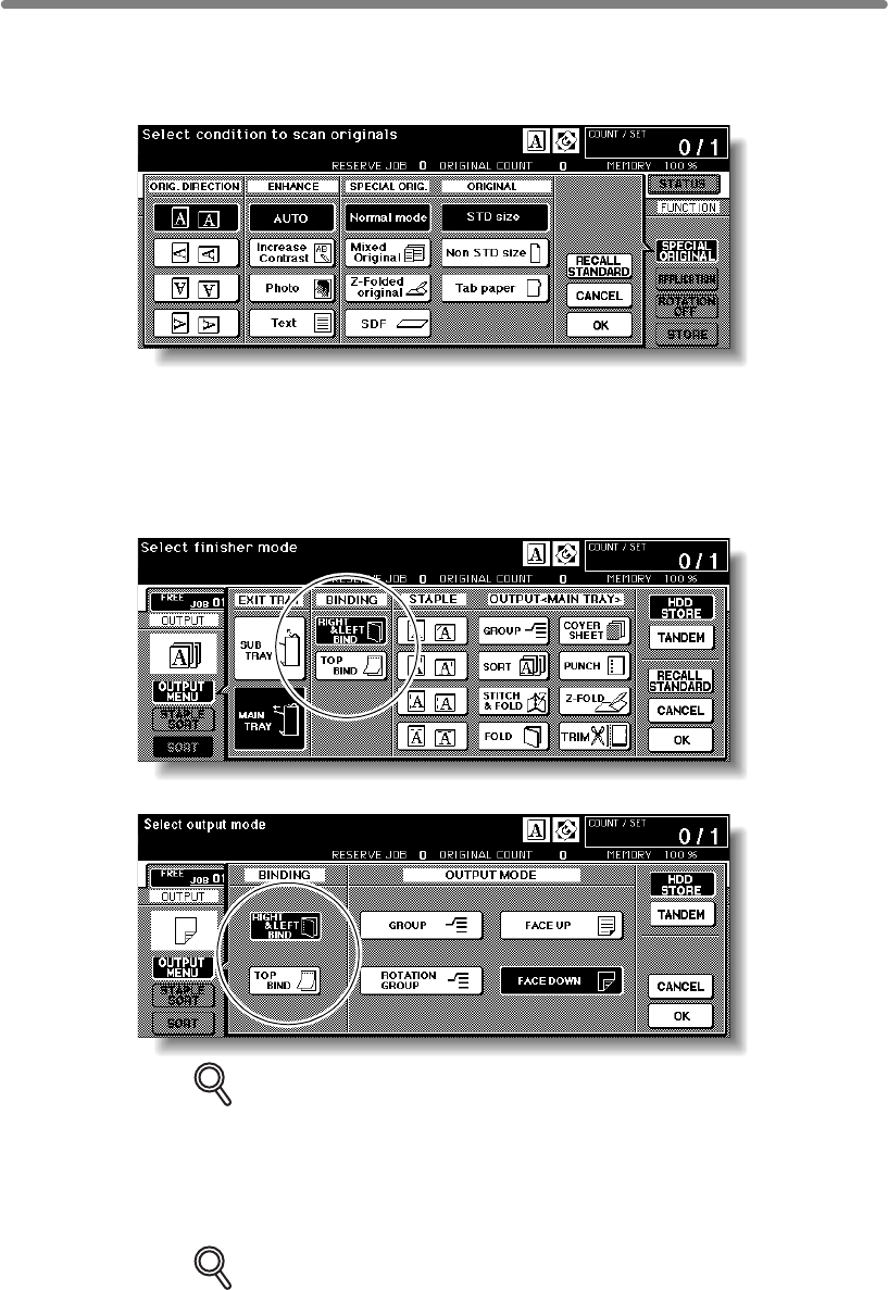
3-22
2. Select the original set direction.
Touch SPECIAL ORIGINAL on the Basic Screen to display the Special Original popup
menu, then touch the desired original direction key to highlight it.
Touch OK to return to the Basic Screen.
3. Select the binding mode.
Touch OUTPUT MENU on the Basic Screen to display the Output Mode popup menu,
then touch the desired binding mode key to highlight it.
DETAILS
Selecting TOP BIND will make copies upside down on the reverse side,
while RIGHT&LEFT BIND copies normally.
Touch OK to return to the Basic Screen.
4. Select additional copy conditions, as desired.
DETAILS
Some incompatible conditions may automatically release the selected copy
mode. In this case, arrange the settings so that they are compatible with the
selected copy mode.
Output Mode popup menu with Finisher
Output Mode popup menu without Finisher
Making Double-Sided Copies (1u2, 2u2) (continued)
3-23
5. Enter the desired print quantity from the control panel keypad.
HINT
See p. 3-7 for details on setting print quantity.
6. Position originals FACE UP in the document feeder according to the
original direction specified in step 2.
HINTS
• See p. 3-2 to p. 3-6 for details on positioning originals.
•
exceeds 100.
7. Press [START].
The machine starts to scan originals, then prints duplex copies when ready for output.
Press [STOP] to suspend the scanning or printing job.
CAUTION
When the finisher / trimmer unit / paper exit tray capacity is
exceeded due to the print quantity selected, remove the copied
sets as they exit; otherwise, mishandled paper will occur.
3
Copying
Operations
Positioning
Originals
Setting Print
Quantity
Set Job During
Warmup
Stop
Scan/Print
Paper Size
Lens Mode
Density
1-2, 2-2
2-1
Multi-Sheet
Bypass Tray
Using
Memory
Output without
Finisher
Binding
Mode
Recalling
Previous Job
Check Mode
& Proof Copy
Interrupt
Mode
Q3219A/Q3220A
Output Modes
Use RADF store mode (p. 3-32 to p. 3-33) when the original count
Making Double-Sided Copies (1u2, 2u2) (continued)
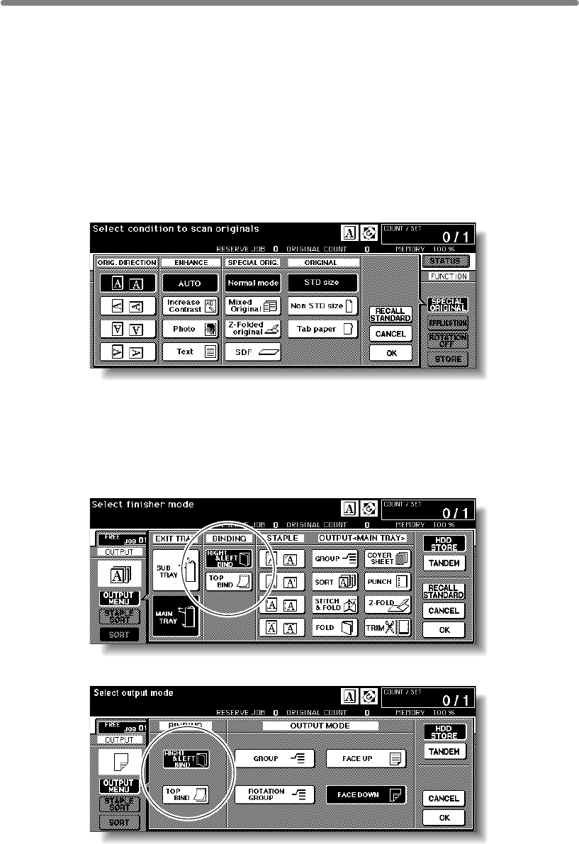
3-24
Using Platen Glass
Use the platen glass to scan originals unsuitable for the document feeder.
>>>Specification for Double-Sided Copying Using Platen Glass<<<
❒Use the Platen store mode.
OHP Interleave
1. Select the original set direction.
Touch SPECIAL ORIGINAL on the Basic Screen to display the Special Original popup
menu, then touch the desired original direction key to highlight it.
Touch OK to return to the Basic Screen.
2. Select the binding mode.
Touch OUTPUT MENU on the Basic Screen to display the Output Mode popup menu,
then touch the desired binding mode key to highlight it.
Output Mode popup menu with Finisher
Output Mode popup menu without Finisher
❒Incompatible Conditions: Face up exit using Secondary (sub) tray, Image Insert,
❒See p. 11-8 for the information on unsuitable RADF originals.
Making Double-Sided Copies (1u2, 2u2) (continued)
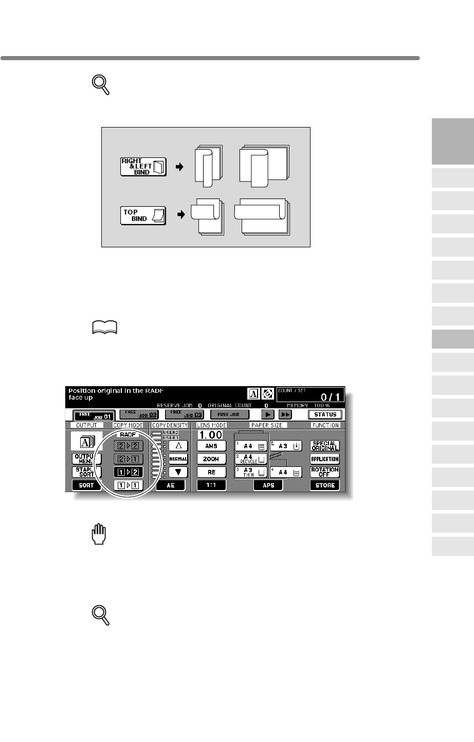
3-25
DETAILS
Selecting TOP BIND will make copies upside down on the reverse side,
while RIGHT&LEFT BIND copies normally.
Touch OK to return to the Basic Screen.
3. Position original FACE DOWN on the platen glass according to the
original direction specified in step 1.
Be sure to start from the first page.
HINTS
• See p. 11-8 for paper sizes detectable on the platen glass.
• See p. 3-6 for details on positioning originals.
4.
The STORE key will be automatically highlighted on the screen.
Reminder!
DO NOT press [AUTO RESET] at this point, otherwise the platen mode will
platen glass.
5. Select additional copy conditions, as desired.
DETAILS
Some incompatible conditions may automatically release the selected copy
mode. In this case, arrange the settings so that they are compatible with the
selected copy mode.
3
1
2
3
1
2
12
312
3
CopiesBinding mode
3
Copying
Operations
Positioning
Originals
Setting Print
Quantity
Set Job During
Warmup
Stop
Scan/Print
Paper Size
Lens Mode
Density
1-2, 2-2
2-1
Multi-Sheet
Bypass Tray
Using
Memory
Output without
Finisher
Binding
Mode
Recalling
Previous Job
Check Mode
& Proof Copy
Interrupt
Mode
Q3219A/Q3220A
Output Modes
Making Double-Sided Copies (1u2, 2u2) (continued)
Touch 1u2 on the Basic Screen to highlight it.
be released to disable the mfp from scanning the original placed on the
3-26
6. Enter the desired print quantity from the control panel keypad.
HINT
See p. 3-7 for details on setting print quantity.
7. Press [START] to scan.
The front side image of the double-sided copy will be scanned into memory.
8. Replace the original on the platen glass with the back side image
original, then press [START].
DETAILS
Repeat this step until all originals are scanned.
Memory indicator on the upper right of the Basic Screen allows you to check
the remaining memory.
To delete the scanned data without printing, press [STOP], then touch
CANCEL on the popup menu to be sure the data is deleted.
9. Touch STORE to exit the Store mode.
STORE will return to the normal display.
10. Press [START] to print.
All the data in memory will be output.
Press [STOP] to suspend the printing job.
CAUTION
When the finisher / trimmer unit / paper exit tray capacity is
exceeded due to the print quantity selected, remove the copied
sets as they exit; otherwise, mishandled paper will occur.
Making Double-Sided Copies (1u2, 2u2) (continued)
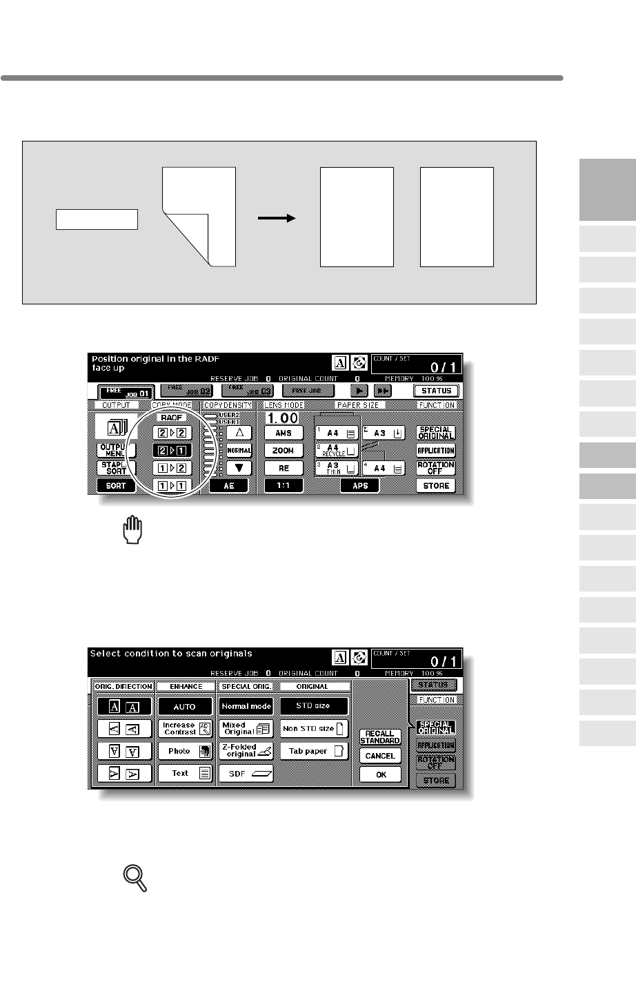
3-27
originals.
1.
Reminder!
press [AUTO RESET].
2. Select the original set direction.
Touch SPECIAL ORIGINAL on the Basic Screen to display the Special Original popup
menu, then touch the desired original direction key to highlight it.
Touch OK to return to the Basic Screen.
3. Select additional copy conditions, as desired.
DETAILS
Some incompatible conditions may automatically release the selected copy
mode. In this case, arrange the settings so that they are compatible with the
selected copy mode.
Double-sided original
Simplex copy
2-1 Copying
Front
Front
Front
Front
Front
Back
Back
Back
Back
Back
Front
Front
Front
Front
Front
Back
Back
Back
3
Copying
Operations
Positioning
Originals
Setting Print
Quantity
Set Job During
Warmup
Stop
Scan/Print
Paper Size
Lens Mode
Density
1-2, 2-2
2-1
Multi-Sheet
Bypass Tray
Using
Memory
Output without
Finisher
Binding
Mode
Recalling
Previous Job
Check Mode
& Proof Copy
Interrupt
Mode
Q3219A/Q3220A
Output Modes
When starting a new copying job, be sure to close the RADF securely, then
Making Single-Sided Copies from Double-Sided Originals (2u1)
Use RADF and select 2u1 copy mode to make single-sided copies from double-sided
Touch 2u1 on the Basic Screen to highlight it.
3-28
4. Enter the desired print quantity from the control panel keypad.
HINT
See p. 3-7 for details on setting print quantity.
5. Position originals FACE UP in the document feeder according to the
original direction specified in step 2.
HINTS
• See p. 3-2 to p. 3-6 for details on positioning originals.
•
exceeds 100.
6. Press [START].
The machine starts to scan originals, then prints simplex copies when ready for output.
Press [STOP] to suspend the scanning or printing job.
CAUTION
When the finisher / trimmer unit / paper exit tray capacity is
exceeded due to the print quantity selected, remove the copied
sets as they exit; otherwise, mishandled paper will occur.
Use RADF store mode (p. 3-32 to p. 3-33) when the original count
Making Single-Sided Copies from Double-Sided Originals (2u1)
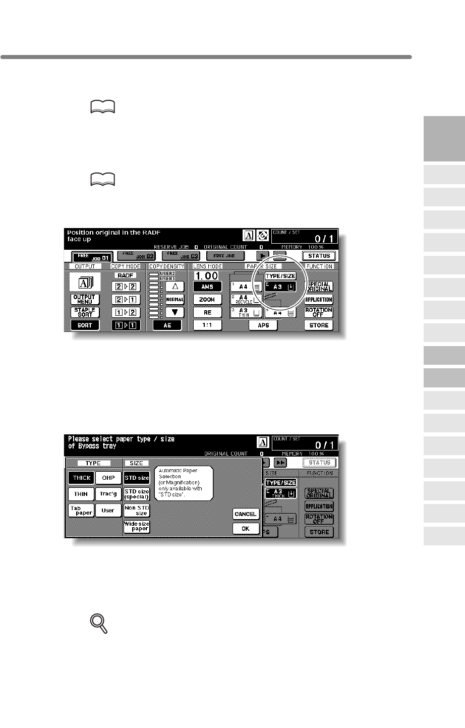
3-29
Copying Using Special Paper (Multi-Sheet Bypass Tray)
Use the Multi-sheet bypass tray to copy using special (non-standard) paper. Specify the
paper type and size to be loaded on the Multi-sheet bypass tray, as described below.
HINT
regular basis, the paper type and size should be specified in the Key
Operator setting. See p. 13-23 to p. 13-24.
1. Open the Multi-sheet bypass tray, and load the copy paper.
HINT
See p. 2-27 for further details.
2. Touch the Bypass key to highlight it.
The TYPE/SIZE key will appear above the Bypass key. APS will be deselected, and
AMS will be highlighted on the Basic Screen.
3. Touch TYPE/SIZE.
The Paper Type/Size popup menu will be displayed.
4. Touch the desired paper type key.
When THICK, THIN, Tab paper, OHP, Trac’g, or User is highlighted, a print job will
conform to the selected paper type.
If no paper type indication is needed, touch the highlighted key to clear the selection in
the TYPE area.
The selection will be reflected on the Basic Screen when restored.
DETAILS
When selecting Tab paper, AMS is automatically selected. The STD size
(special) and Non STD size cannot be selected, and the loaded copy paper
3
Copying
Operations
Positioning
Originals
Setting Print
Quantity
Set Job During
Warmup
Stop
Scan/Print
Paper Size
Lens Mode
Density
1-2, 2-2
2-1
Multi-Sheet
Bypass Tray
Using
Memory
Output without
Finisher
Binding
Mode
Recalling
Previous Job
Check Mode
& Proof Copy
Interrupt
Mode
Q3219A/Q3220A
Output Modes
cannot be fed in 1u2 or 2u2 copying.
When loading special paper in the engine tray or in the HCI to use on a
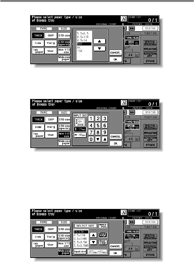
Copying Using Special Paper (Multi-Sheet Bypass Tray) (continued)
3-30
5. Specify the paper size.
When STD size (special) is highlighted, the popup menu will appear.
Use arrow keys to scroll to the desired size. In this case, both the paper size and type
selected will be indicated on the Basic Screen.
When Non STD size is highlighted, the popup menu will appear.
To set the vertical size, touch the vertical size key to highlight it, then use the keypad
on the popup menu to enter the vertical size, or use arrows to scroll to that number.
To set the horizontal size, touch the horizontal size key to highlight it, then use the
keypad on the popup menu to enter the horizontal size, or use arrows to scroll to that
number.
In this case, the Special indication and paper type selected will be displayed on the
Basic Screen, but the actual size information cannot be displayed.
When Wide paper is highlighted, the Select Size popup menu will appear.
Use arrow keys to scroll to the desired wide size, then specify the precise dimensions
of paper to be used according to the procedure as follows.
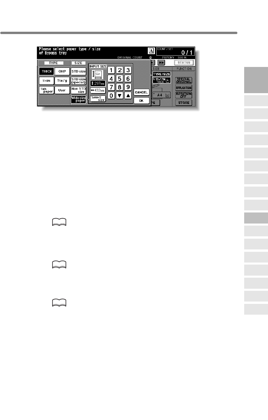
Copying Using Special Paper (Multi-Sheet Bypass Tray) (continued)
3-31
(1) Touch Input size. The Input Size popup menu will appear.
(2) Touch the vertical size key to highlight it. Use the keypad on the popup menu to
enter the vertical size, or use arrow keys to scroll to that number.
The entered number should fall within the range from the vertical size of the
standard size corresponding to the selected wide size, to a maximum of 314mm.
(3) Similarly, touch the horizontal size key to highlight it, then use the keypad on the
popup menu to enter the horizontal size, or use arrow keys to scroll that number.
The entered number should fall within the range from the horizontal size of the
standard size corresponding to the selected wide size, to a maximum of 459mm.
(4) Touch Select size to return to the Select Size popup menu.
Touch Lead edge or Rear edge to select the image starting position.
6. Touch OK to return to the Basic Screen.
7. Select additional copy conditions, as desired.
HINTS
• See p. 8-12 to p. 8-13 for details on copying non-standard size or tab
paper originals.
• See p. 9-16 to p. 9-17 for details on copying onto OHP films.
8. Enter the desired print quantity from the control panel keypad.
HINT
See p. 3-7 for details on setting print quantity.
9. Position original(s) FACE UP in the document feeder or FACE DOWN
on the platen glass.
HINT
See p. 3-2 to p. 3-6 for details on positioning originals.
10. Press [START].
3
Copying
Operations
Positioning
Originals
Setting Print
Quantity
Set Job During
Warmup
Stop
Scan/Print
Paper Size
Lens Mode
Density
1-2, 2-2
2-1
Multi-Sheet
Bypass Tray
Using
Memory
Output without
Finisher
Binding
Mode
Recalling
Previous Job
Check Mode
& Proof Copy
Interrupt
Mode
Q3219A/Q3220A
Output Modes
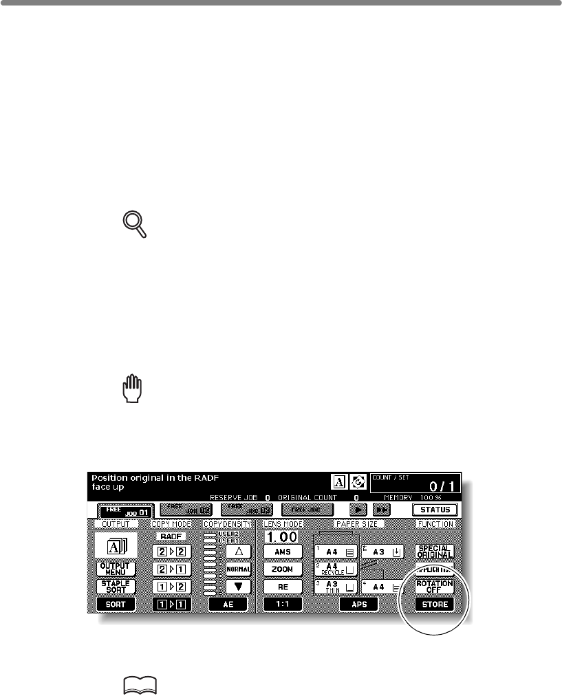
3-32
Copying Using Memory
This section describes various copying features available on this machine using built-in
memory.
To Scan Originals into Memory (Store Mode)
Store mode allows you to scan all the originals first, then to start a continuous printing
job.
Use Platen store mode for originals that cannot be fed through the document feeder
due to thickness, size or condition.
DETAILS
>>>Specification for Store Mode<<<
Overlay Memory
1. Make copying selections, as desired.
Reminder!
press [AUTO RESET].
2. Touch STORE on the Basic Screen to highlight it.
3. Enter the desired print quantity from the control panel keypad.
HINT
See p. 3-7 for details on setting print quantity.
❒Incompatible with Platen store mode: Storing image in Overlay Memory
Use RADF store mode to scan a large amount of originals.
RADF tray capacity is 100; however, more than 100 originals can be
❒Incompatible with RADF store mode: Image Insert, Dual Page, Storing image in
scanned into memory using RADF store mode.
When starting a new copying job, be sure to close the RADF securely, then
Copying Using Memory (continued)
3-33
4. Position original(s).
Using platen glass:
Place original FACE DOWN. Start scanning from the first page.
Reminder!
procedure.
Position originals FACE UP.
If the number of originals exceeds 100, divide them into blocks not exceeding 100
sheets and load them from the block with the first page.
HINT
See p. 3-2 to p. 3-6 for details on positioning originals.
5. Press [START] to scan.
DETAILS
Repeat steps 4 and 5 until all originals are scanned.
Memory indicator on the upper right of the Basic Screen allows you to check
the remaining memory.
To delete the scanned data without printing, press [STOP], then touch EXIT
on the confirmation screen to be sure the data is deleted.
HINT
Should memory overflow occur frequently, it is recommended that you
contact your service representative to extend the memory capacity in your
machine.
6. Touch STORE to exit the Store mode.
STORE will return to the normal display.
7. Press [START].
All the data in memory will be output.
Press [STOP] to suspend the printing job.
CAUTION
When the finisher / trimmer unit / paper exit tray capacity is
exceeded due to the print quantity selected, remove the copied
sets as they exit; otherwise, mishandled paper will occur.
3
Copying
Operations
Positioning
Originals
Setting Print
Quantity
Set Job During
Warmup
Stop
Scan/Print
Paper Size
Lens Mode
Density
1-2, 2-2
2-1
Multi-Sheet
Bypass Tray
Using
Memory
Output without
Finisher
Binding
Mode
Recalling
Previous Job
Check Mode
& Proof Copy
Interrupt
Mode
Q3219A/Q3220A
Output Modes
When Dual Page, Non-Image Area Erase, Auto detection mode of Repeat,
or AUTO Layout is selected, keep the RADF open throughout the scanning
Using RADF:
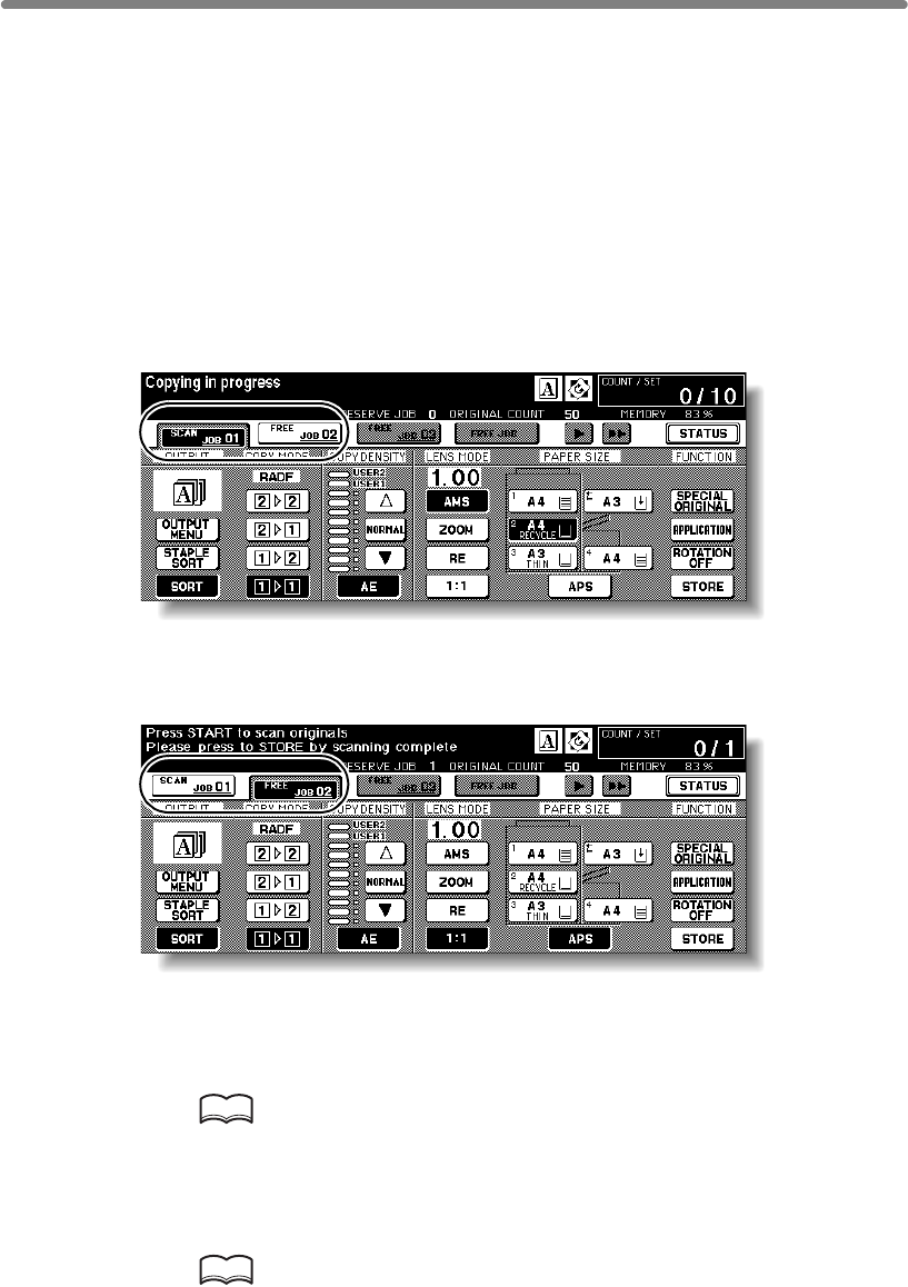
Copying Using Memory (continued)
3-34
To Set Next Copying Job (Reserve)
The Reserve function allows you to set up a new job while a current job is in process.
When the current job is finished, the Reserve job starts printing immediately.
>>>Specifications for Reserve<<<
❒Job settings: Max. 10 (current job plus 9 reserve jobs)
❒When the current job is in Store mode, Image Insert, or Dual Page, the reserve job
❒Incompatible Conditions: Interrupt copying, Scanning in Store mode, Proof copy,
Storing image in Overlay Memory
1. Press [START] to start scanning/printing for the current job.
FREE JOB
will become active to show that the reserve job setting is now available
.
2. Touch FREE JOB to highlight it.
The Reserve Job Setting Screen will be displayed.
On the Reserve Job Setting Screen, all keys on the LCD and control panel will function
for the reserve job.
3. Select copy conditions for the reserve job, as desired.
HINT
When trouble occurs while setting the reserve job, the PRINT or SCAN JOB
key on the Basic Screen will change to JAM or ADD PAPER key. See p. 5-8
to p. 5-10.
4. Position original(s) after completing the scan for the current job.
HINT
See p. 3-2 to p. 3-6 for details on positioning originals.
setting will be available after the mfp starts to print the current job.
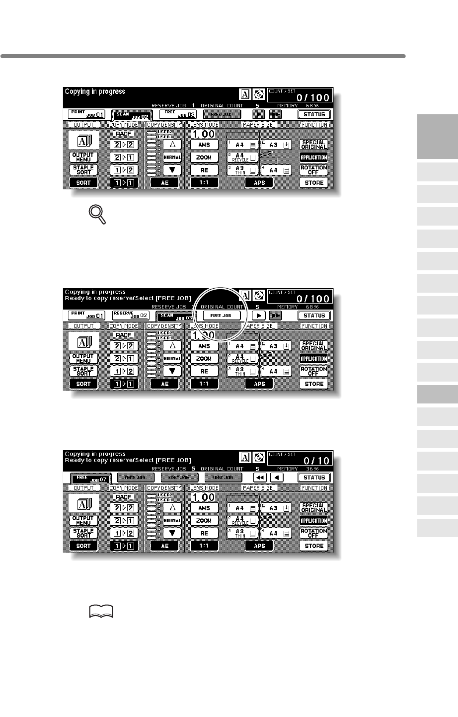
Copying Using Memory (continued)
3-35
5. Press [START] to start scanning for the reserve job.
DETAILS
When setting more than one reserve job, the next reserve job setting will be
When setting the fourth copying job, touch the active
FREE JOB
key at the far right to
scroll to the next reserve setting screen. Another three reserve job settings (04-06) will
be available.
When setting the seventh copying job, touch the active
FREE JOB
key at the far right to
scroll to the next reserve setting screen. Another four reserve job settings (07-10) will
be available.
When completed, the Basic Screen for the current printing job will be restored.
To scroll to the next/previous screen, touch the arrow keys displayed at the right side of
the folder keys.
HINT
When trouble occurs on a reserve job which is not currently displayed on the
screen, the arrow key to scroll to that job will blink. See p. 5-8 to p. 5-10.
3
Copying
Operations
Positioning
Originals
Setting Print
Quantity
Set Job During
Warmup
Stop
Scan/Print
Paper Size
Lens Mode
Density
1-2, 2-2
2-1
Multi-Sheet
Bypass Tray
Using
Memory
Output without
Finisher
Binding
Mode
Recalling
Previous Job
Check Mode
& Proof Copy
Interrupt
Mode
Q3219A/Q3220A
Output Modes
available after the mfp starts to scan for the previous reserve job.

Copying Using Memory (continued)
3-36
6. Copying of the reserve job will start automatically after completing the
current job.
CAUTION
When the finisher / trimmer unit / paper exit tray capacity is
exceeded due to the print quantity selected, remove the copied
sets as they exit; otherwise, mishandled paper will occur.
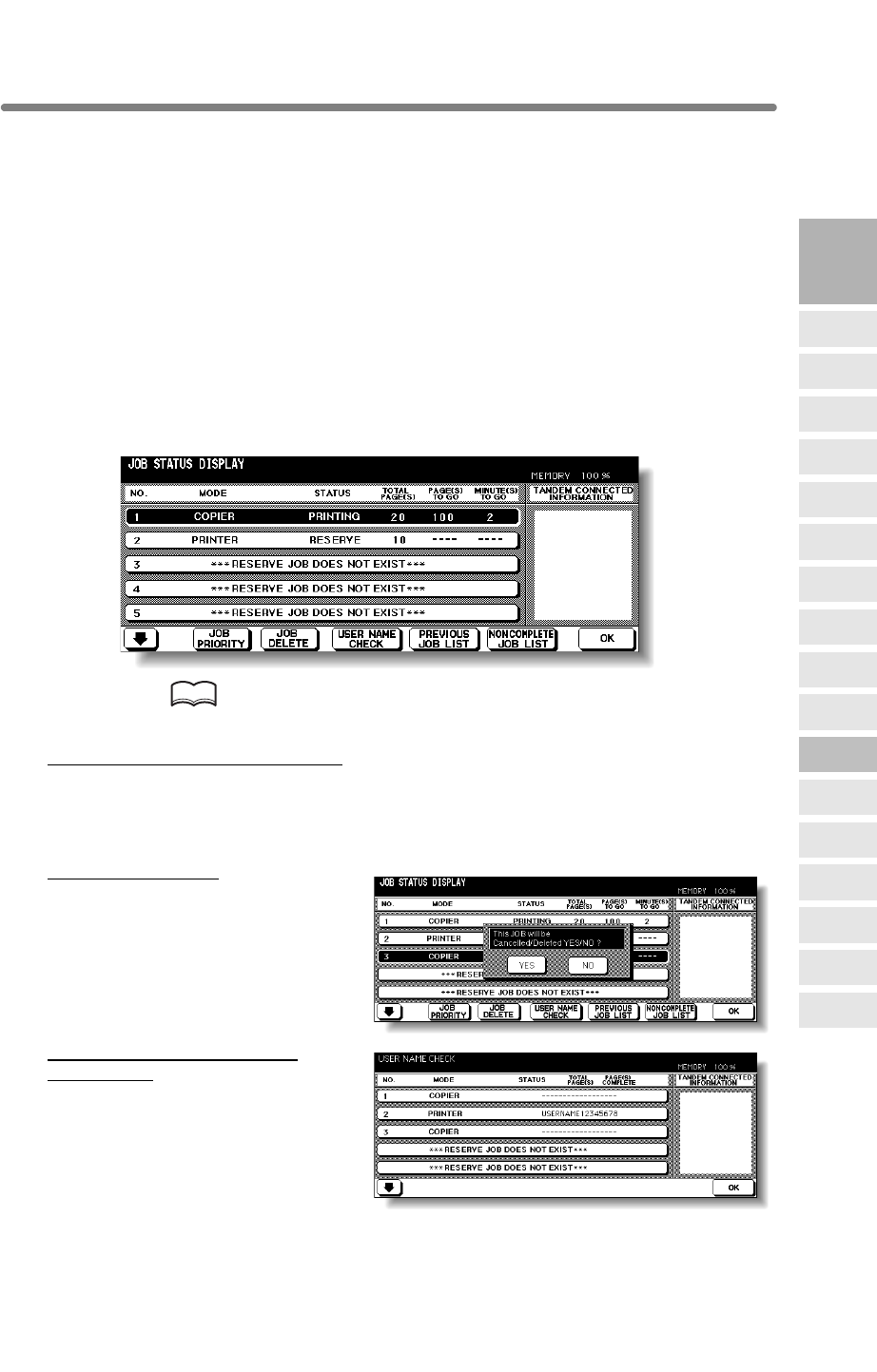
Copying Using Memory (continued)
3-37
To Check/Control Jobs in Progress (Job Status Screen)
The Job Status Screen allows you to perform the following functions.
• Confirm machine status • Change order of reserve job
• Delete reserve job • View previous job list
• View noncomplete job list
1. Touch STATUS on the Basic Screen.
The Job Status Screen will be displayed.
Check the current status of the machine.
2. Perform the desired setting on the screen.
If more than six jobs are entered, use the page down arrow key at the lower left corner
of the screen to scroll to the desired job.
HINT
See the next page for details of the screen.
To change the order of reserve job:
Touch to highlight the desired reserve job key, then touch JOB PRIORITY.
The highlighted reserve job is advanced by one in printing order unless the job
preceding the selected one is already in progress.
To clear reserve job:
Touch to highlight the desired reserve
job key, then touch
JOB CLEAR
.
Touch YES to clear the highlighted
reserve job, or NO to cancel.
information):
Touch USER NAME CHECK to
Screen.
Check the user name indicated on
the right side of the job number and
operatio mode.
Touch OK to return to the Job Status
Screen.
3
Copying
Operations
Positioning
Originals
Setting Print
Quantity
Set Job During
Warmup
Stop
Scan/Print
Paper Size
Lens Mode
Density
1-2, 2-2
2-1
Multi-Sheet
Bypass Tray
Using
Memory
Output without
Finisher
Binding
Mode
Recalling
Previous Job
Check Mode
& Proof Copy
Interrupt
Mode
Q3219A/Q3220A
Output Modes
display the User Name Check
To check user name (not mfp
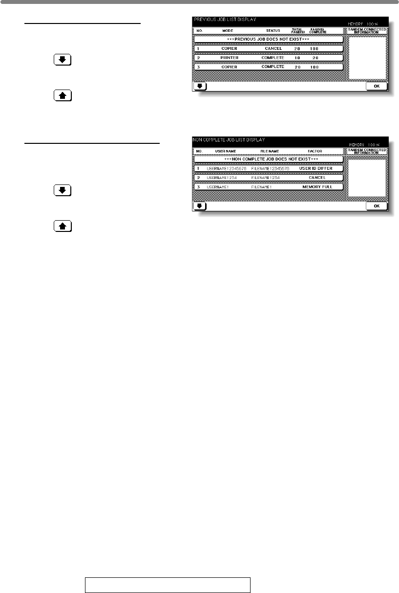
Copying Using Memory (continued)
3-38
To display previous job list:
Touch PREVIOUS JOB LIST to
display the Previous Job List Screen.
Touch to scroll to the next page.
Up to 16 previous jobs (4 pages) can
be displayed.
Touch to return to the previous
page.
Touch OK to return to the Job Status Screen.
To display noncomplete job list:
Touch NONCOMPLETE JOB LIST
to display the Noncomplete Job List
Screen.
Touch to scroll to the next page.
Up to 16 noncomplete jobs (4 pages)
can be displayed.
Touch to return to the previous
page.
Touch OK to return to the Job Status Screen.
3. Touch OK on the Job Status Screen.
The Basic Screen will be restored.
Contents of Job Status Screen
NO. : Displays the No. (01-99) for each job assigned to the machine.
MODE: Displays the machine’s current mode of operation. Three modes are listed below.
PRINTER
SCANNER
STATUS:
READY : Ready to use in each mode
INTERRUPT : Interrupting the previous job
ERROR : Error in each mode
PRINTING : Printing in each mode
NO PAPER : No paper in copy/print mode
STOP : Stop in each mode
RESERVE : Ready to reserve
JAM : Jam in each mode
TOTAL PAGE(s): Displays the number of scanned pages for each job. (0 to 9999)
PAGE(s) TO GO: Displays the remaining copy count of the job.
0 to 9999 (The number exceeding 9999 will be displayed as 9999^.)
Copy count
= No. of scanned pages x Print quantity
MINUTE(s) TO GO: Displays the time (in minutes) required for completing the job.
Exceeding 999 minutes: 999^
Shorter than 1 minute: <1
Other: The following message will be displayed on the bar when the reserved job does not exist.
RESERVED JOB DOES NOT EXIST
COPIER
Displays the current status of the machine for each job.
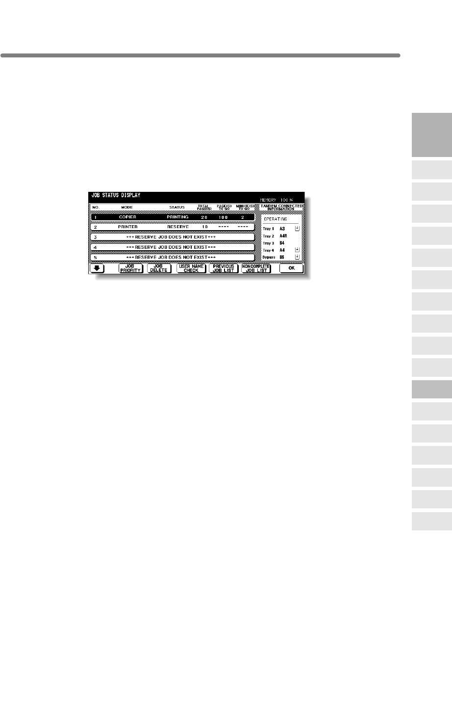
Copying Using Memory (continued)
3-39
TANDEM CONNECTED INFORMATION
Displays the tray information and current status of the other machine when
[Information]
Paper size loaded in each tray
Paper out indicator (when depleted in the tray)
Current status: OPERATING
STOP
PAPER SUPPLY
JAM
ERROR
3
Copying
Operations
Positioning
Originals
Setting Print
Quantity
Set Job During
Warmup
Stop
Scan/Print
Paper Size
Lens Mode
Density
1-2, 2-2
2-1
Multi-Sheet
Bypass Tray
Using
Memory
Output without
Finisher
Binding
Mode
Recalling
Previous Job
Check Mode
& Proof Copy
Interrupt
Mode
Q3219A/Q3220A
Output Modes
two mfp are connected and operate in tandem mode.
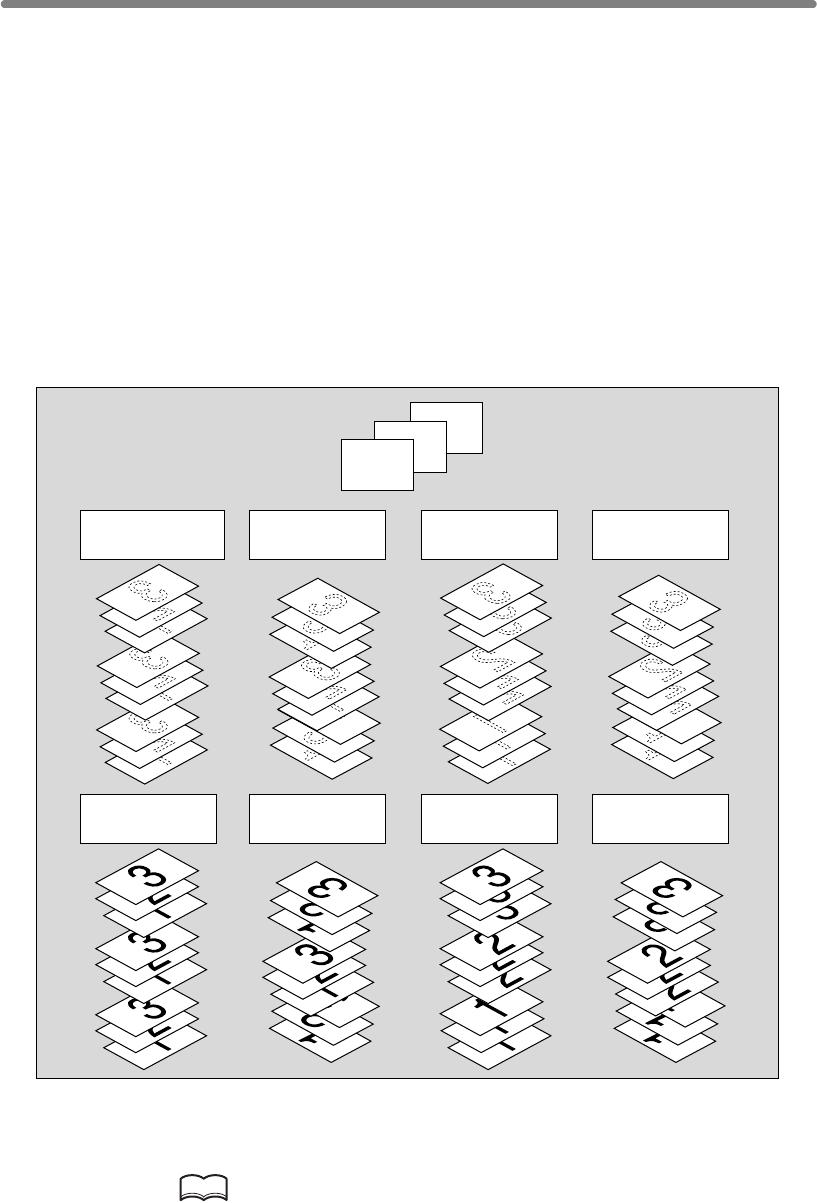
3-40
Output Mode for Machine without Finisher
The Non-sort mode is initially selected.
1Non-sort mode copies the original set in amounts determined by the print quantity
setting, then outputs sorted sets normally.
2
Rotation sort mode rotates every other sorted sets by 90° upon exit, provided the same
paper size is loaded in two trays, one tray with paper loaded in portrait orientation and
the other tray with paper loaded in landscape orientation, e.g., A4 and A4R.
3Group mode copies each original page in amounts determined by the print quantity
setting, then outputs grouped sets normally.
4
Rotation group mode rotates every other grouped set by 90° upon exit, provided the
same paper size is loaded in two trays, one tray with paper loaded in portrait orientation
and the other tray with paper loaded in landscape orientation, e.g., A4 and A4R.
Using Face Up mode in combination with the above four modes, simplex copies and
odd numbered duplex copies exit face up on the exit tray.
1. When using Rotation sort or Rotation group mode, load the same
paper size into two trays in different orientation.
HINT
Non-sort mode is initially selected. Key Operator can change the initial
output mode. See p. 13-10.
3
2
1
Originals
Face down
rotation sort
Face down
group
Face down
rotation group
Face down
non-sort (default)
Face up
rotation sort
Face up
group
Face up
rotation group
Face up
non-sort
Example:
3-set copies
This section describes the output modes for a mfp without the Finisher.
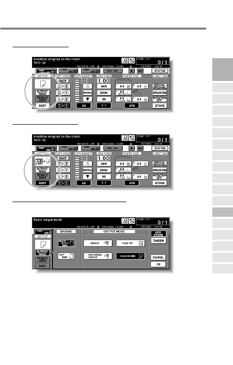
Output Mode for Machine without Finisher (continued)
3-41
2. Select the desired output mode.
To select Non-sort mode:
Confirm that
OUTPUT MENU
and
SORT
are not highlighted on the Basic Screen.
To select Rotation sort mode:
Confirm that
OUTPUT MENU
is not highlighted, then touch
SORT
to highlight it
.
To select Group, Rotation group, or Face up mode:
(1) Touch OUTPUT MENU on the Basic Screen. The Output Mode popup menu will
be displayed.
(2) Touch to highlight the desired mode key.
To use Face Up mode in combination, simply touch to highlight FACE UP instead
of FACE DOWN.
(3) Touch OK.
The Basic Screen will be restored, with OUTPUT MENU highlighted.
3. Select additional copy conditions, as desired.
3
Copying
Operations
Positioning
Originals
Setting Print
Quantity
Set Job During
Warmup
Stop
Scan/Print
Paper Size
Lens Mode
Density
1-2, 2-2
2-1
Multi-Sheet
Bypass Tray
Using
Memory
Output without
Finisher
Binding
Mode
Recalling
Previous Job
Check Mode
& Proof Copy
Interrupt
Mode
Q3219A/Q3220A
Output Modes
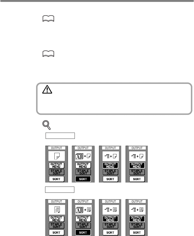
Output Mode for Machine without Finisher (continued)
3-42
4. Enter the desired print quantity from the control panel keypad.
HINTS
• See p. 11-3 to be sure that the exit tray capacity is not exceeded.
• See p. 3-7 for details on setting print quantity.
5. Position original(s) FACE UP in the document feeder or FACE DOWN
on the platen glass.
HINT
See p. 3-2 to p. 3-6 for details on positioning originals.
6. Press [START].
Press [STOP] to suspend the scanning or printing job.
CAUTION
When the paper exit tray capacity is exceeded due to the print
quantity selected, remove the copied sets as they exit;
otherwise, mishandled paper will occur.
DETAILS: Output Icons on the Basic Screen
Face Down
Non-sort Rotation sort Group Rotation group
Face Up
Non-sort Rotaion sort Group Rotation group
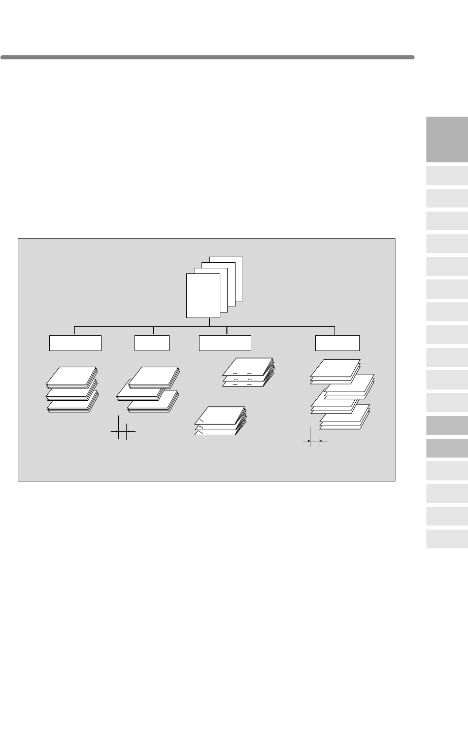
3-43
Output Mode for Machine with Finisher
Primay (Main) Tray:
1Non-sort mode simply means that the offset-stacker finisher modes are not selected.
Copies will be stacked upon exit without being offset by sorted sets.
2Sort mode outputs multiple copies of the original set, having each sorted set offset
by 30mm upon exit.
3Staple-sort mode offsets and staples each sorted set. Up to 50 sheets (or within
5mm thick) can be stapled.
4Group mode groups together multiple copies of each original and offsets the sets by
30mm upon exit.
4
123
4
3
2
1
4
3
2
1
4
3
2
1
4
3
2
1
4
3
2
1
4
3
2
1
1
1
1
2
2
2
4
4
4
3
3
3
4
3
2
14
3
2
1
4
3
2
1
4
3
2
14
3
2
1
4
3
2
1
Example:
Make 3 copied sets
from 4 original sheets
Offset by 30mm
1 oblique
staple
Offset by 30mm
2 staples
Group
Staple-sortSortNon-sort
3
Copying
Operations
Positioning
Originals
Setting Print
Quantity
Set Job During
Warmup
Stop
Scan/Print
Paper Size
Lens Mode
Density
1-2, 2-2
2-1
Multi-Sheet
Bypass Tray
Using
Memory
Output without
Finisher
Binding
Mode
Recalling
Previous Job
Check Mode
& Proof Copy
Interrupt
Mode
Finisher Q3219A/Q3220A is equipped with a primary (main) and a secondary
(sub) exit trays. Without using any optional equipment, each exit tray provides the
output modes as described below.
Q3219A/Q3220A
Output Modes
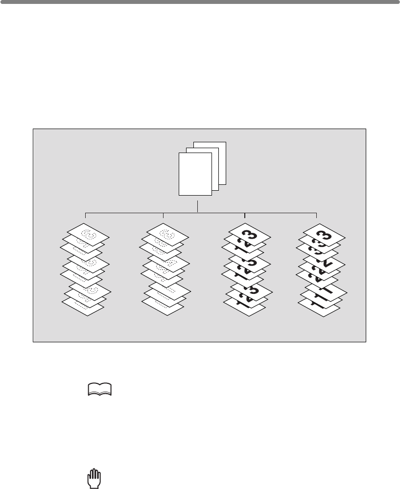
Output Mode for Machine with Finisher (continued)
3-44
Secondary (Sub) Tray:
1Face down non-sort exit outputs simplex copies and odd numbered duplex copies
face down, without offsetting the sorted sets.
2Face down group exit outputs multiple copies of each original face down, without
offsetting the grouped sets upon exit.
3Face up non-sort exit outputs simplex copies and odd numbered duplex copies face
up, without offsetting the sorted sets.
4Face up group exit outputs multiple copies of each original face up, without offsetting
the grouped sets upon exit.
HINT
>>>Specification for Output Modes with Finisher<<<
❒Incompatible with Sort mode: Using platen glass (unless Image Insert, Dual Page,
or Platen store mode is used), Fold, Stitch & Fold, OHP Interleave
❒Incompatible with Staple-sort mode: Using platen glass (unless Image Insert, Dual
Page, or Platen store mode is used), Fold, Stitch & Fold, OHP Interleave
Reminder!
Using excessively curled paper or some types of thin paper in Staple-sort
mode may cause poor results in arrangement of the stapled sets.
store mode is used), Proof Copy, Fold, Stitch & Fold, Sheet/Cover Insertion, Chapter,
Combination, Booklet, OHP Interleave, Image Insert, Repeat
glass (unless Platen store mode is used), Proof Copy, Fold, Stitch & Fold, Punch,
Cover sheet feeding, Sheet/Cover Insertion, Chapter, Combination, Booklet, OHP
Interleave, Image Insert, Repeat
Fold, Punch, Cover sheet feeding
Example:
Make 3 copied sets
Face down
non-sort
Face up
non-sort
Face up
group
Face down
group
123
❒
Incompatible with Group mode: 1u2 or 2u2 mode using platen glass (unless Platen
❒
Incompatible with Group using Secondary (sub) tray: 1u2 or 2u2 mode using platen
❒Incompatible with Face Up exit: 1u2 or 2u2 mode using platen glass, Fold, Stitch &
Follow the procedure on the next page to change the output mode, as desired.
See Section 7 for the output modes using Finisher options.
The mfp is initially set to output to Primary (main) tray in Sort mode.
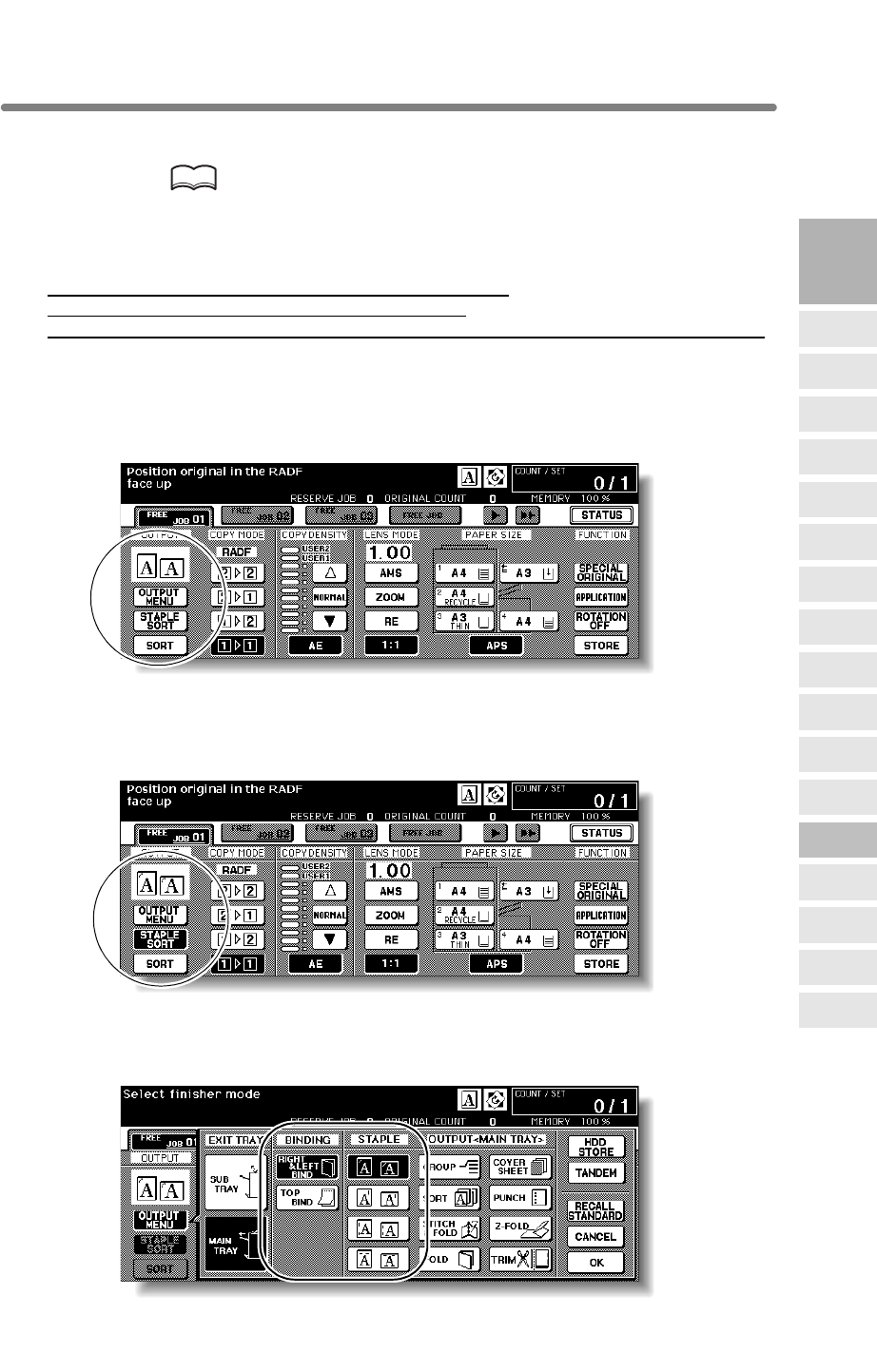
Output Mode for Machine with Finisher (continued)
3-45
1.
HINT
The Sort mode using Primay (main) tray is initially selected.
Key Operator can change the initial output mode. See p. 13-10.
2. Select the desired output mode.
To set Non-sort or Sort mode using Primary (main) tray: proceed to the next step.
To set Staple-sort mode using Primary (main) tray: proceed to step 4.
To set Group mode using Primary (main) tray or output to Secondary (sub) tray:
proceed to step 5.
3. To set Non-sort or Sort mode:
Check that SORT is already highlighted on the Basic Screen in initial condition.
To select Non-sort mode, touch SORT to deselect it.
Proceed to step 6.
4. To set Staple-sort mode:
(1) Touch STAPLE SORT on the Basic Screen to highlight it.
The staple position icon will be displayed in the output icon area.
(2) Touch OUTPUT MENU on the Basic Screen to display the Output Mode popup
menu.
3
Copying
Operations
Positioning
Originals
Setting Print
Quantity
Set Job During
Warmup
Stop
Scan/Print
Paper Size
Lens Mode
Density
1-2, 2-2
2-1
Multi-Sheet
Bypass Tray
Using
Memory
Output without
Finisher
Binding
Mode
Recalling
Previous Job
Check Mode
& Proof Copy
Interrupt
Mode
Q3219A/Q3220A
Output Modes
Close the RADF securely, then press [AUTO RESET].
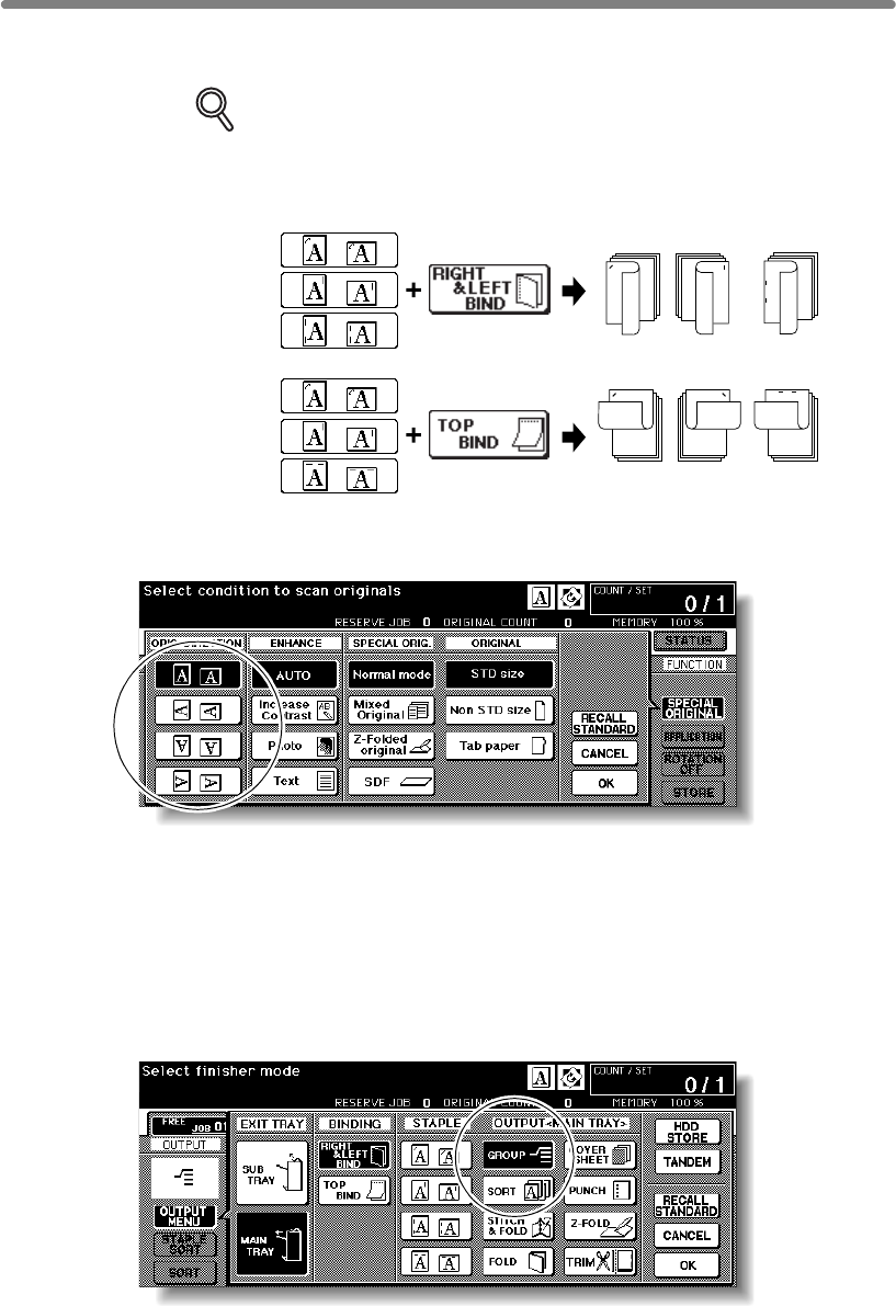
Output Mode for Machine with Finisher (continued)
3-46
(3) Touch the desired staple position key, then touch OK. The Basic Screen will be
restored, with the selected staple position icon displayed.
DETAILS
When making double-sided copies, select the desired binding mode on the
Output Mode popup menu. See p. 3-47 for detail.
(4) Touch SPECIAL ORIGINAL on the Basic Screen to display the Special Original
popup menu.
(5) Touch the desired original set direction key, then touch OK to return to the Basic
Screen.
Proceed to step 6.
5. To set Group mode or output to Secondary (sub) tray:
Touch OUTPUT MENU on the Basic Screen to display the Output Mode popup menu.
Select the desired output mode.
To set the Group mode, touch GROUP to highlight it.
3
1
2
3
12
3
1
2
123123
1
2
3
Staple position Binding mode
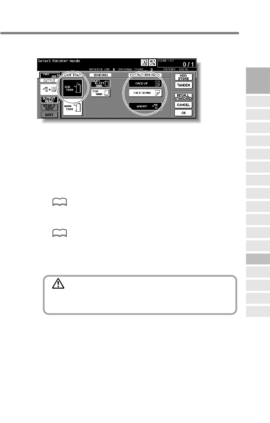
Output Mode for Machine with Finisher (continued)
3-47
To set the output to Secondary (sub) tray, touch SUB TRAY to display the popup
menu, then touch to highlight the desired key(s).
• Face down non-sort exit: FACE DOWN
• Face down group exit: FACE DOWN and GROUP
• Face up non-sort exit: FACE UP
• Face up group exit: FACE UP and GROUP
Touch OK to restore the Basic Screen. OUTPUT MENU will be highlighted, and the
output icon of the selected output mode will be displayed in the output icon area.
6. Select additional copy conditions, as desired.
7. Enter the desired print quantity from the control panel keypad.
HINT
See p. 11-3~p. 11-4 to be sure that the finisher capacity is not exceeded.
8. Position original(s).
HINT
See p. 3-2 to p. 3-6 for details on positioning originals.
9. Press [START].
Press [STOP] to suspend the scanning or printing job.
CAUTION
When the finisher exit tray capacity is exceeded due to the print
quantity selected, remove the copied sets as they exit;
otherwise, mishandled paper will occur.
3
Copying
Operations
Positioning
Originals
Setting Print
Quantity
Set Job During
Warmup
Stop
Scan/Print
Paper Size
Lens Mode
Density
1-2, 2-2
2-1
Multi-Sheet
Bypass Tray
Using
Memory
Output without
Finisher
Binding
Mode
Recalling
Previous Job
Check Mode
& Proof Copy
Interrupt
Mode
Q3219A/Q3220A
Output Modes
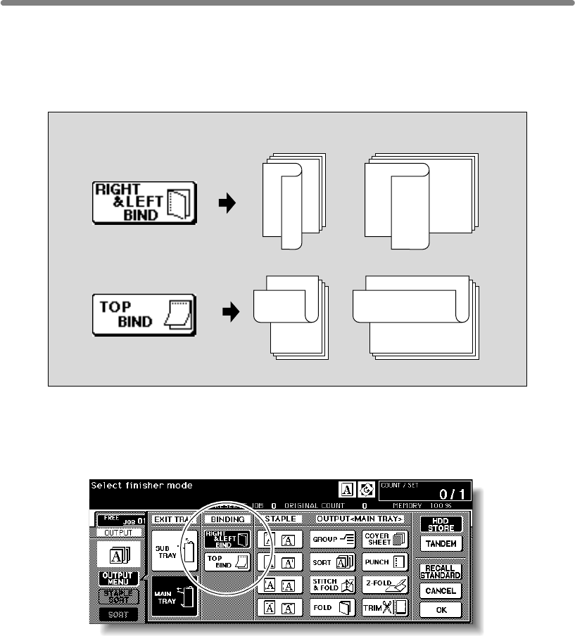
3-48
Selecting Binding Mode
popup menu to obtain the desired copy result.
Right & Left Bind: Normal duplex copies
Top Bind: Duplex copies arranged upside down on the reverse side
1. Touch OUTPUT MENU to display the Output Mode popup menu.
2. Touch to highlight the desired binding mode key.
3. Touch OK to return to the Basic Screen.
3
1
2
3
1
2
1
2
31
2
3
CopiesBinding mode
When copying in 1u2 or 2u2 mode, specify the binding mode on the Output Mode
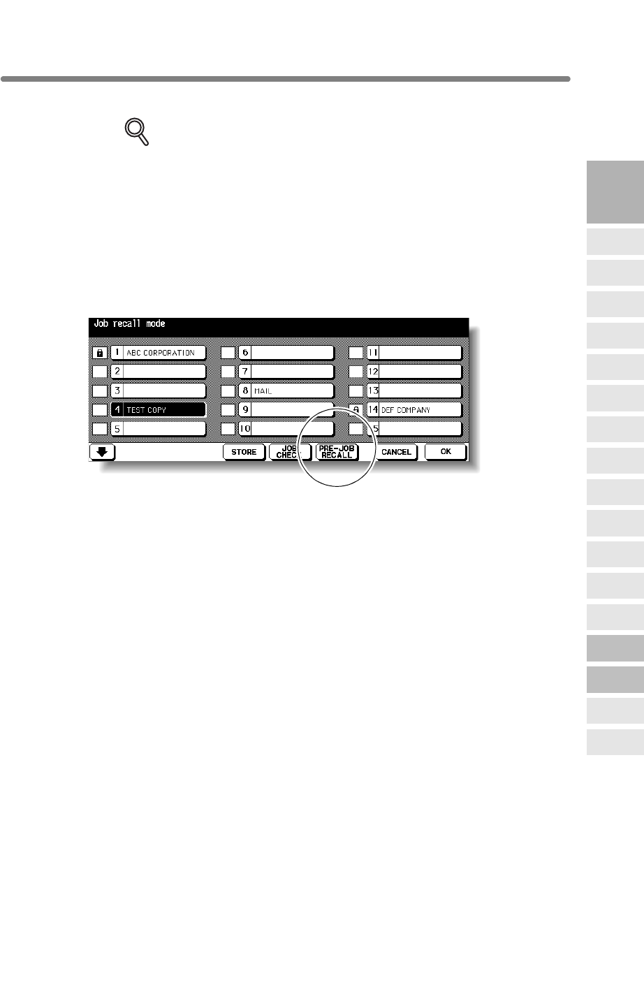
3-49
Recalling Previous Job Settings
Follow the procedure below to copy with a previous job’s settings.
DETAILS
• Only the last-completed output job settings can be recalled as the
previous job settings. Non-complete job or reserve job settings cannot be
recalled, even if the setting operations have been made last.
• The previous job settings can be recalled, even after the machine power
is turned off then on.
1. Press [JOB MEMORY] on the control panel.
The Job No. Selection Screen will be displayed.
2. Touch PRE-JOB RECALL.
3. Touch OK to return to the Basic Screen.
The settings of the previous output job is recalled on the screen.
4. Change the settings recalled on the screen, if desired.
5.
When all settings are acceptable, position original(s) in the document
feeder or on the platen glass, then press [START].
3
Copying
Operations
Positioning
Originals
Setting Print
Quantity
Set Job During
Warmup
Stop
Scan/Print
Paper Size
Lens Mode
Density
1-2, 2-2
2-1
Multi-Sheet
Bypass Tray
Using
Memory
Output without
Finisher
Binding
Mode
Recalling
Previous Job
Check Mode
& Proof Copy
Interrupt
Mode
Q321º9A/Q3220A
Output Modes
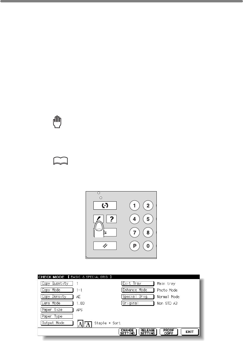
3-50
Checking Feature Selections and Proof Copying
Use the Check mode to confirm copying selections before starting print operation.
In this mode, use Proof copy to produce a sample of the copied set before making
multiple copies. This is a convenient and cost effective way of viewing the results of the
following copying selections.
• Copying conditions using Store mode • Booklet
• Sheet/Cover insertion • Image insert
• Chapter • Dual Page
• Combination • Program job
>>>Specifications for Check Mode and Proof Copy<<<
❒Proof copy is unavailable with Group output mode.
1.
Select the desired copy conditions and enter the desired print quantity.
Reminder!
press [AUTO RESET].
2. Position original(s).
HINT
See p. 3-2 to p. 3-6 for details on positioning originals.
3. Press [CHECK] on the control panel.
The Check Screen will be displayed.
Verify the settings made for the current job.
• If settings are OK, proceed to step 8.
• If a sample copy is needed, proceed to step 6.
• If making any setting change from the Check Screen, proceed to the next step.
• If releasing any setting from the Check Screen, proceed to step 5.
CHECK
PRINT
JOB MEMORY
C
L
COUNTER
AUTO RESET
HELP
❒Proof copy cannot be used for testing the Userset density.
❒Proof copy is available when using RADF, or Platen store mode for multiple originals.
When starting a new copying job, be sure to close the RADF securely, then
SCAN
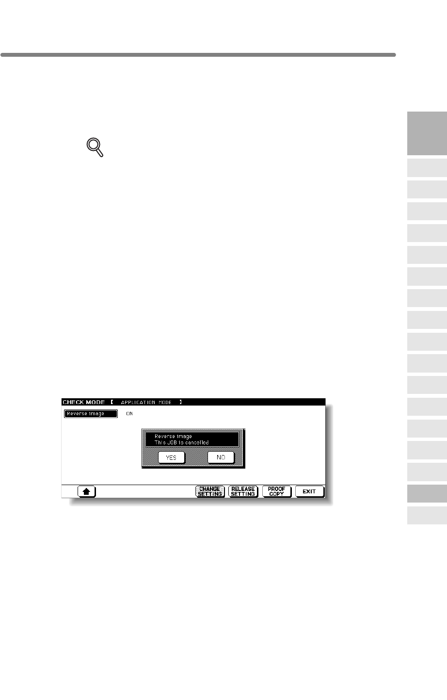
Checking Feature Selections and Proof Copying (continued)
3-51
4. To change the settings:
Touch the desired copying condition key on the Check Screen to highlight it.
Any key that cannot be highlighted indicates that the copying condition cannot be
changed from the Check Screen.
Touch CHANGE SETTING.
The LCD will display an appropriate screen to change the copying condition selected.
DETAILS
• Selecting a basic copying condition key will display the Basic Screen.
• Selecting Enhance Mode, Special Orig., or Original key will display the
Special Original popup menu.
• Selecting an application function key will display the Change Application
Selection Screen.
When
BOOK MARK
has been checked on a subsequent screen, selecting
the application function key will jump to that screen. See p. 9-2 for details.
•CHANGE SETTING will not function for the following application
functions, however they can be released by touching RELEASE
SETTING: Non-Image Area Erase, Reverse Image, AUTO Layout, Full-
Image Area, Overlay.
Change the setting as desired, then restore the Check Screen to return to the checking
steps.
From the Basic Screen, press [CHECK] to return to the Check Screen.
From the Special Original popup menu or Change Application Selection Screen, touch
OK to return to the Check Screen.
• When making a set or sample copy, proceed to step 6.
• To start printing without proofcopying, proceed to step 8.
5. To release the settings:
Touch the desired copying condition key on the Check Screen to highlight it, then touch
RELEASE SETTING.
The confirmation screen will appear on the Check Screen.
Touch YES to cancel the function, or NO to restore.
• If making a sample copy, proceed to the next step.
• To start printing, proceed to step 8.
3
Copying
Operations
Positioning
Originals
Setting Print
Quantity
Set Job During
Warmup
Stop
Scan/Print
Paper Size
Lens Mode
Density
1-2, 2-2
2-1
Multi-Sheet
Bypass Tray
Using
Memory
Output without
Finisher
Binding
Mode
Recalling
Previous Job
Check Mode
& Proof Copy
Interrupt
Mode
Q3219A/Q3220A
Output Modes
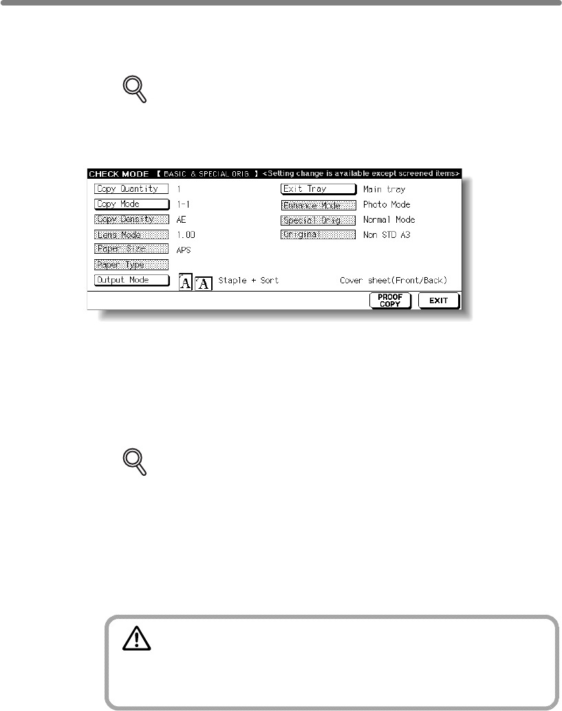
Checking Feature Selections and Proof Copying (continued)
3-52
6. Press [PROOF COPY] on the control panel or touch PROOF COPY on
the Check Screen.
A sample copy will be output.
DETAILS
• Press [STOP] to suspend the proof copying. In this case, the scanned
image data will not be deleted from memory.
• You cannot change or release selections that appeared dimmed after
proof copying.
• When the copy result is satisfactory, proceed to the next step.
• When any setting change is required, return to step 4, then repeat proof copying, as
required.
If the desired selection cannot be changed, press [STOP] to delete all the data in
memory, then press [AUTO RESET] to restart the job setting.
7. Change the print quantity, as required.
DETAILS
Proof copy can be performed as needed, until the print quantity amount on
the Basic Screen reaches zero. (Note that the print quantity amount on the
Check Screen does not change.)
If required, change the print quantity on the Basic Screen.
8. Press [START].
sets.
CAUTION
When the finisher / trimmer unit / paper exit tray capacity is
exceeded due to the print quantity selected, remove the copied
sets as they exit; otherwise, mishandled paper will occur.
If the print quantity is not changed, the mfp will output the rest, except the sample
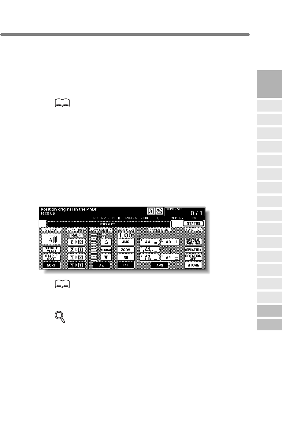
3-53
Interrupt Copying
Use the Interrupt mode to interrupt copying in progress to perform a simple job. When
interrupt copying is completed, the settings for the initial job restore automatically and
the Basic Screen displays.
• Continuously printing the image stored in memory
• Scanning the originals into memory
• Scanning the originals into memory while printing in Reserve mode
HINT
If desired, Key Operator can change the timing to stop current machine
operation for interrupt copying.
Note that the compatible copying conditions vary according to the timing
selected. See p. 13-39 to p. 13-44.
>>>Specification for Interrupt Mode<<<
The Basic Screen is not displayed.
Overlay Memory is in use.
The Call for Service message displays or a paper misfeed occurs.
❒Incompatible: Reserve, Storing image in Overlay Memory
1. Press [INTERRUPT] on the control panel.
The [INTERRUPT] LED turns on and all JOB indicators on the Basic Screen change
to INTERRUPT.
HINT
The timing to enter the Interrupt mode varies according to the job in
See the following page.
DETAILS
reserve job.
For details of Reserve mode, see p. 3-34 to p. 3-36.
2. Set copy conditions, as desired.
The initial settings in Interrupt mode are as follows.
: ON
AE : ON
Lens Mode : 1.00 (100%)
APS : ON
Print Quantity : 1
Finisher : Main Tray in Sort mode
3
Copying
Operations
Positioning
Originals
Setting Print
Quantity
Set Job During
Warmup
Stop
Scan/Print
Paper Size
Lens Mode
Density
1-2, 2-2
2-1
Multi-Sheet
Bypass Tray
Using
Memory
Output without
Finisher
Binding
Mode
Recalling
Previous Job
Check Mode
& Proof Copy
Interrupt
Mode
Copy Mode
Q3219A/Q3220A
Output Modes
RADF
: 1u1
Interrupt copying is available when the mfp is performing the following operations:
scanning the reserve job originals clears the settings selected for the
progress on the machine when [INTERRUPT] is pressed.
In Reserve mode, pressing [INTERRUPT] before the mfp finishes
❒The Interrupt mode cannot be selected with the following mfp conditions:
Interrupt Copying (continued)
3-54
DETAILS
Remove any document from the platen glass or from the document feeder, if
present.
3. Position original(s).
HINT
See p. 3-2 to p. 3-6 for details on positioning originals.
4. Press [START] to start the interrupt copying.
DETAILS
When [CHECK] is pressed during Interrupt copying, the information
displayed reflects the initial copy job settings. Check mode will not display
Interrupt copy job information.
5. When Interrupt copying is completed, press [INTERRUPT] again.
The [INTERRUPT] LED turns out and the INTERRUPT indicator on the Basic Screen
returns to the JOB indicators.
The settings of the initial job will be restored on the Basic Screen.
6. Press [START] to resume copying.
CAUTION
When the finisher / trimmer unit / paper exit tray capacity is
exceeded due to the print quantity selected, remove the copied
sets as they exit; otherwise, mishandled paper will occur.
DETAILS
For particular jobs in progress, copying will cease only after certain phases
of the immediate operation are completed, as indicated by the [INTER-
RUPT] LED conditions described below.
• Collectively printing image stored in memory
The LED blinks until one set of the current job is printed.
Then the LED remains steady for the temporary job performed in
Interrupt mode.
• Scanning originals into memory
The LED blinks until scanning is completed for all originals placed in the
document feeder.
Then, the LED remains steady for the temporary job performed in
Interrupt mode.
• Scanning originals into memory while printing in Reserve mode
all originals placed on the document feeder, and prints one set of the
Reserved job.
The LED remains steady for the temporary job performed in Interrupt
mode.
The LED blinks until the mfp completes the current printing job, scans

44
Job Memory
&Help Mode
Job Memory
Help Mode
Job Memory & Help Mode
How to Use Helpful Functions
Storing Job Conditions (Job Memory: Job Store) ................................... 4-2
Recalling Stored Job Settings (Job Memory: Job Recall) .................. 4-5
Displaying Screen for Operation Guide (Help Mode) ............................. 4-6
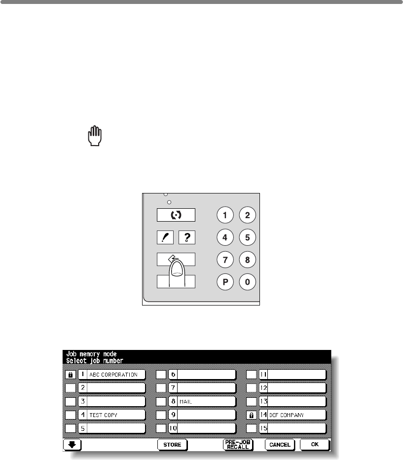
4-2
Storing Job Conditions (Job Memory: Job Store)
Use Job Store to store up to 30 frequently used copy job settings, which can be
recalled at any time. The stored jobs can be given alphabetical names.
>>>Specifications for Job Memory<<<
❒All copying functions can be selected.
❒Interrupt mode cannot be used while in Job Memory.
1.
Make job selections from the Basic Screen and/or Application Selection
Screen.
Reminder!
press [AUTO RESET].
2. Press [JOB MEMORY] on the control panel.
The Job No. Selection Screen will be displayed.
3. Touch STORE.
The Job Store Check Screen will be displayed.
CHECK
PRINT
JOB MEMORY
C
COUNTER
AUTO RESET
HELP
When starting a new copying job, be sure to close the RADF securely, then
SCAN
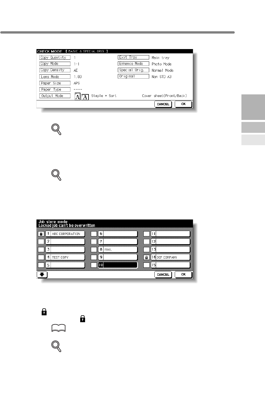
Storing Job Conditions (Job Memory: Job Store) (continued)
4-3
4. Review the settings on the Job Store Check Screen.
Check that the selections made in step 1 are correctly entered.
DETAILS
If any correction is required, touch CANCEL to return to the Basic Screen.
Make new selections, then restart the Job Store operation from step 2.
5. Touch OK.
The Job No. Selection Screen will be restored.
DETAILS
To suspend the storing job after step 6, press [AUTO RESET].
Job Memory mode will be cancelled, and the Basic Screen will return from
any screen.
6. Touch to highlight one of the keys numbered from 1~30 to store the
job under that number.
The screen displays 15 job number keys. The arrow key at the lower left corner can be
used to scroll to the next/previous page.
A blank key indicates that no job is stored under that key, and a named job without a
lock icon ( ) displayed can be overwritten.
The key with a lock icon ( ) displayed is locked and cannot be selected.
HINT
To lock or unlock a job, and to delete a locked job, see p. 13-22.
DETAILS
If you wish to cancel the job number selection, touch CANCEL to restore the
Basic Screen, which displays the settings made in step 1.
If you wish to cancel the settings, press [AUTO RESET].
4
Job Memory
&Help Mode
Job Memory
Help Mode
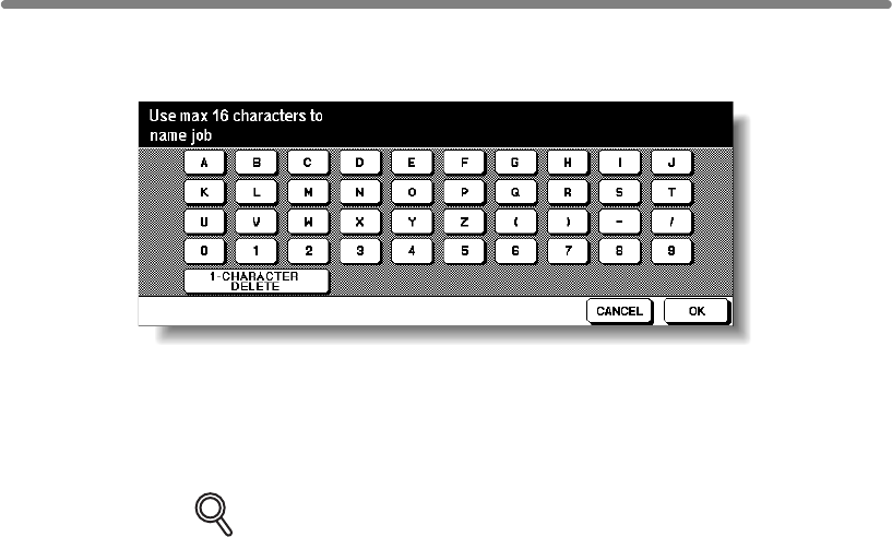
Storing Job Conditions (Job Memory: Job Store) (continued)
4-4
7. Touch OK.
The Job Name Registration Screen will be displayed.
8. Enter a job name.
Enter a job name in up to 16 characters, using the touch screen alphabet keypad.
To correct an entry, touch 1-CHARACTER DELETE repeatedly to delete each
character entered, then enter the correct job name.
DETAILS
If you do not wish to enter a name, simply touch OK. The key displays 16
asterisks (*) in place of a name.
When changing the name of a job previously stored, touch 1-CHARAC-
TER DELETE repeatedly to delete the previous name, then enter the new
name.
9. Touch OK.
The Job No. Selection Screen will be restored.
Check that the job name has been correctly entered.
10. Touch OK to complete the setting and return to the Basic Screen.
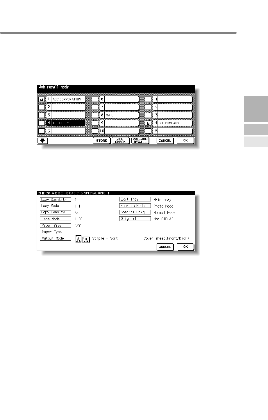
4-5
Recalling Stored Job Settings (Job Memory: Job Recall)
Use Job Recall to recall jobs that are already stored in Job Memory.
1. Press [JOB MEMORY] on the control panel.
The Job No. Selection Screen will be displayed.
2. Touch to highlight a job number key to select a job you want to recall.
The screen displays 15 job number keys. If required, scroll to the next page with the
arrow key to reach the desired job number key (16~30).
3. If desired, touch JOB CHECK.
The Job Recall Check Screen displays to enable you to review the settings.
4. Touch OK.
The settings of the selected job will be recalled on the restored Basic Screen.
To cancel the recall mode, touch CANCEL to return to the Basic Screen.
5. Position original(s), then press [START] to print.
4
Job Memory
&Help Mode
Job Memory
Help Mode
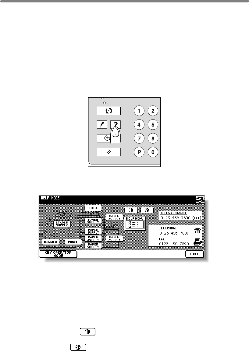
4-6
Displaying Screen for Operation Guide (Help Mode)
The Help Screen provides you with the information about the current screen mode and
about setting procedures. Help mode can be accessed from any screen except Job
Memory and Key Operator Screens.
Help mode provides two types of Help Screens according to the current screen mode:
1Help Screen accessed from Basic Screen
2Help Screen accessed from screens other than Basic Screen
To Display Help Screen from Basic Screen
1. Return to the Basic Screen, then press [HELP].
The Help Screen will be displayed.
2. Touch the desired key to display specific information.
•STAPLE SUPPLY provides information on replacing staple cartridge.
•PUNCH provides information on emptying trash basket.
•TRIMMER provides information on emptying trash basket.
•
•TONER SUPPLY provides information on adding toner.
•PAPER SUPPLY provides information on loading paper in each tray.
•
functions. When a function item is touched, the Help Screen displays information
specific to that topic.
•PANEL CONTRAST displays the screen to adjust the contrast of the LCD
panel.
•WEEKLY TIMER provides the current setting information of Weekly Timer.
This key appears when the Weekly Timer function is turned ON.
•FOR ASSISTANCE displays the extension number of the Key Operator.
•TELEPHONE/FAX displays the phone/fax number of your service centre.
CHECK
SCAN
PRINT
JOB MEMORY
C
COUNTER
AUTO RESET
HELP
RADF provides information on positioning originals in the document feeder.
HELP MENU displays the Help Menu Screen which provides a list of all of the mfp
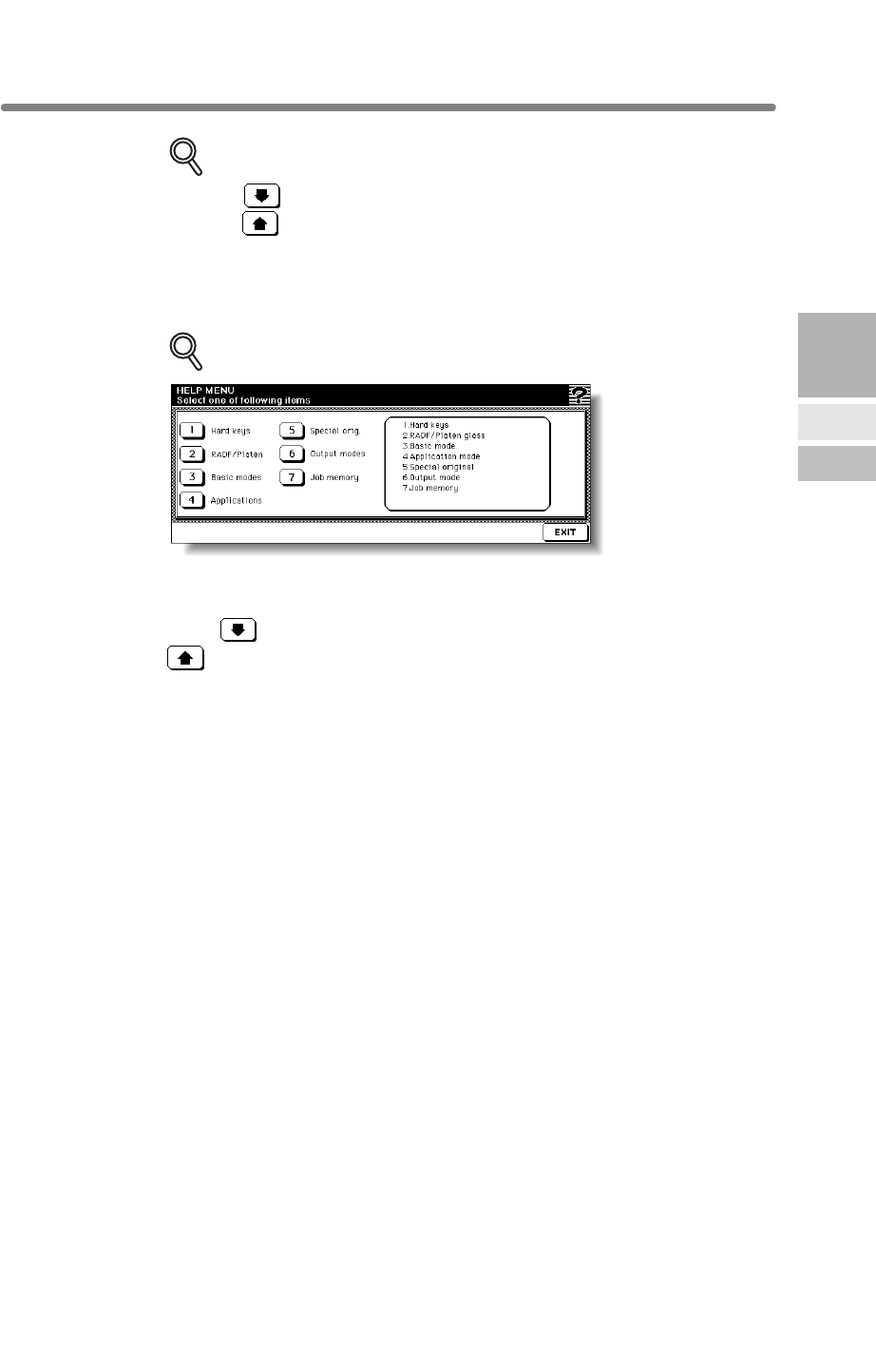
Displaying Screen for Operation Guide (Help Mode) (continued)
4-7
DETAILS
• Touch on the Help Screen, if provided, to scroll to the next page.
Touch to return to the previous page.
• Touch KEY OPERATOR MODE to enter the Key Operator mode. See p.
13-2.
3. Touch EXIT to return to the Basic Screen.
DETAILS: Help Menu Screen
Select one of the 7 help menu items on the Help Menu Screen to display
subsequent Help Screens.
Touch on the Help Screen, if provided, to scroll to the next page. Touch
to return to the previous page.
Touch MENU on the subsequent Help Screen to return to the Help Menu
Screen, then touch EXIT to restore the Basic Screen.
•
•
and maintenance of the document feeder and platen glass.
• “3. Basic modes” displays the information on basic functions provided on
the Basic Screen.
• “4. Applications” displays operational information on 16 application
functions provided on the Application Selection Screen.
• “5. Special orig.” displays the information on functions provided on the
Special Original popup menu.
• “6. Output modes” displays the information on Finisher functions.
• “7. Job memory” displays the information on Job Memory.
4
Job Memory
&Help Mode
Job Memory
Help Mode
“1. Hard keys” displays the information on control panel buttons.
“2. RADF/Platen” displays the information on unsuitable RADF originals
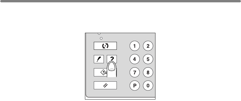
Displaying Screen for Operation Guide (Help Mode) (continued)
4-8
To Display Help Screen from Other Screens
1. While in any screen other than the Basic Screen, press [HELP].
The Help Screen displays to provide the information about the current screen mode
and setting procedures.
2. Touch EXIT.
The screen that was displayed before pressing [HELP] will be restored.
CHECK
SCAN
PRINT
JOB MEMORY
C
COUNTER
AUTO RESET
HELP

55
Trouble-
shooting
Call for
Service
Preventive
Maintenance
Clearing
Mishandled
Paper
JAM Key
ADD PAPER
Key
Memory
Overflow
Power OFF/ON
Screen
Copying
Hints
Troubleshooting
How to Handle Machine Troubles
When “Call for Service” Message Is Displayed ...................................... 5-2
Preventive Maintenance ..................................................................... 5-4
Clearing Mishandled Paper .................................................................... 5-6
When “JAM” Appears on Folder Key (Or Arrow Key Flashes) ........... 5-8
W
hen “ADD PAPER” Appears on Folder Key (Or Arrow Key Flashes)
... 5-10
W
hen “Memory Full” Message Is Displayed (Memory Overflow)
..........5-11
When Power OFF/ON Screen Is Displayed ......................................... 5-13
Troubleshooting Tips ........................................................................ 5-14
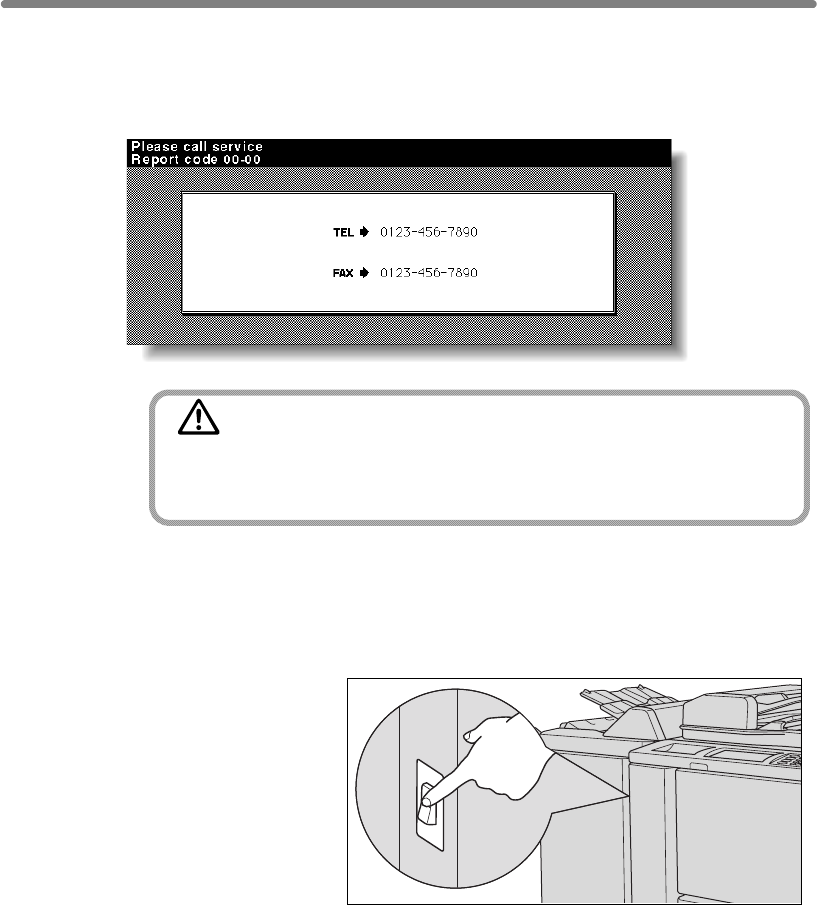
5-2
When “Call for Service” Message Is Displayed
A “Call for Service” message indicates a machine condition that requires the attention
of your service representative.
The Call for Service Screen usually displays the telephone and facsimile numbers of
your service representative.
CAUTION
When the Call for Service Screen is displayed, be sure to
contact your service representative immediately by following
the procedure below.
1. Make note of the Report code No. indicated in the second line of the
message area.
2. Turn OFF the power switch.
3. Unplug the machine.
4. Contact your service representative and report the condition and
code No.
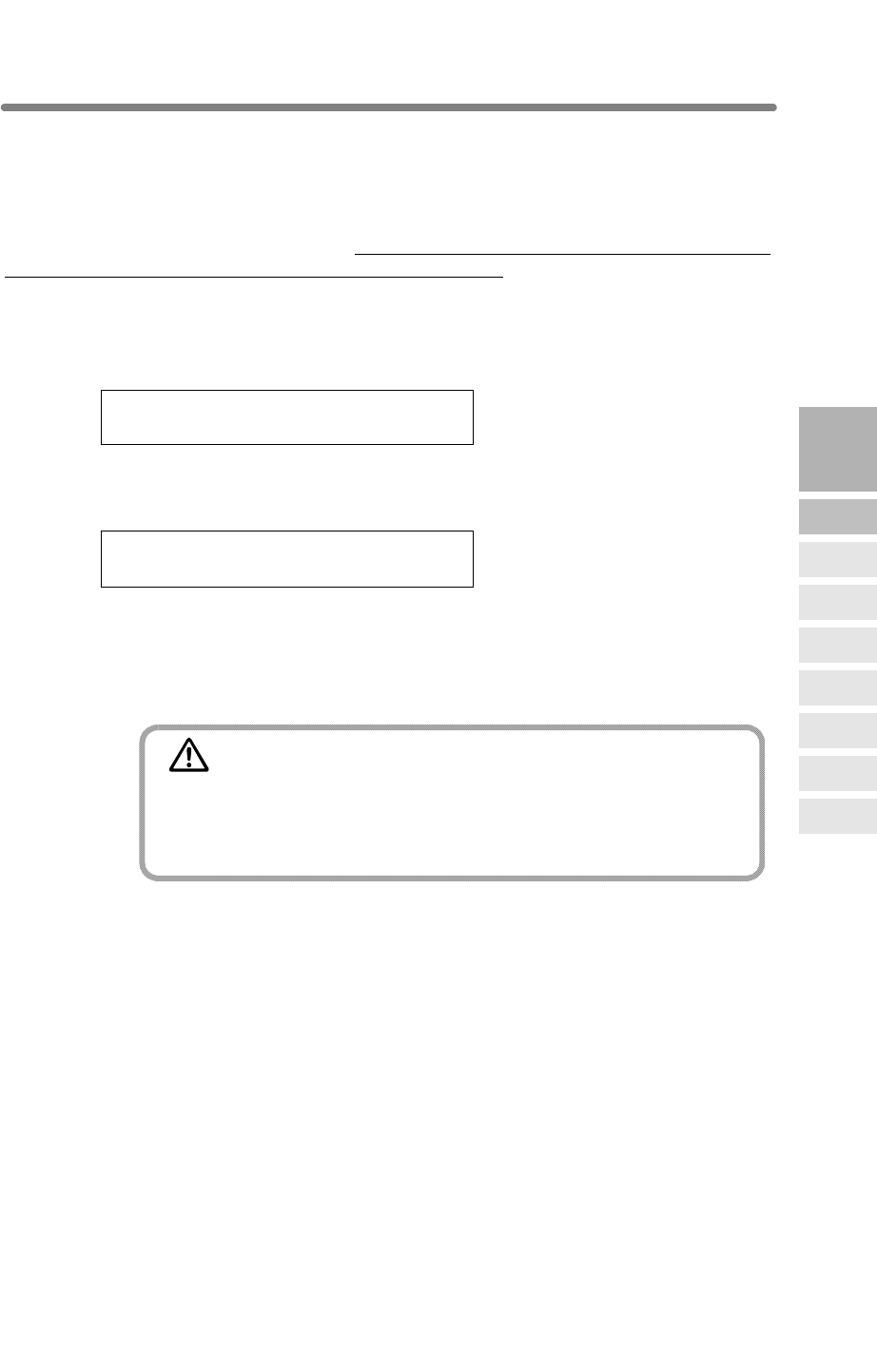
When “Call for Service” Message Is Displayed (continued)
5-3
If the message shown below is displayed on the Call for Service Screen, you may
consult your service representative. Be sure to utilize the limited function only
temporarily, and arrange for machine repair immediately.
1.
displayed in the message area instead of the Report code.
ex. Tray 2 failure
Press AUTO to select except this tray
2. Press [AUTO RESET].
Please switch ON/OFF
E 18-2
Make note of the Report code No.
3. Turn OFF then ON the power switch.
A copying job can continue without using the troubled portion of the machine (ex. Tray
2).
CAUTION
EVEN IF THE COPYING JOB CAN BE CONTINUED WITH THE
ABOVE OPERATION, BE SURE TO CONTACT YOUR SERVICE
REPRESENTATIVE IMMEDIATELY WHEN THE CALL FOR
SERVICE SCREEN IS DISPLAYED.
5
Trouble-
shooting
Call for
Service
Preventive
Maintenance
Clearing
Mishandled
Paper
JAM Key
ADD PAPER
Key
Memory
Overflow
Power OFF/ON
Screen
Copying
Hints
Limited Use of the mfp in Trouble
continue operating the mfp on a limited function basis and utilize the trays and ADU
that are not affected by the trouble. To obtain this limited functionality of the mfp,
If the limited use of the mfp is available, the following message is
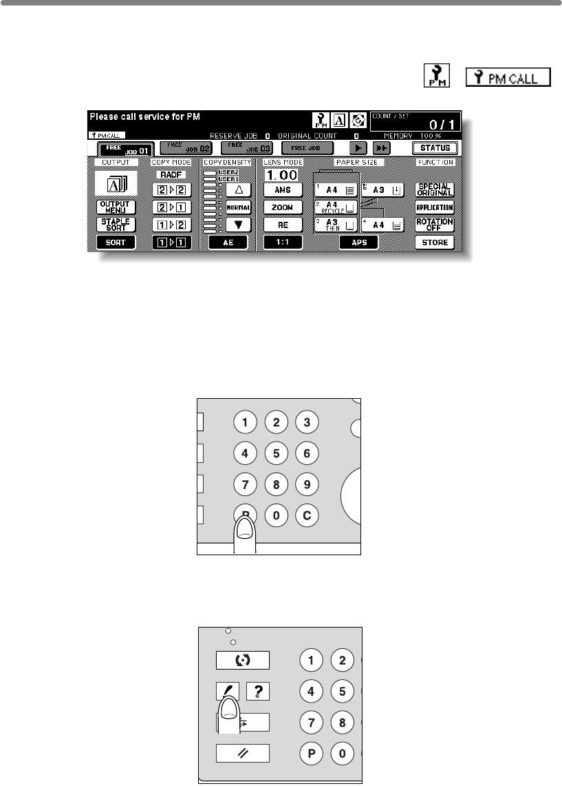
5-4
Preventive Maintenance
(PM) will be required for maintaining optimal performance.
When preventive maintenance is due, a message and two icons ( ) ( )
will prompt you to contact your service representative for maintenance.
To Check the PM Counter
Follow the procedure below to check the PM counter to estimate the time when
Preventive Maintenance is due.
1. Press [P (COUNTER)] on the control panel.
The Counter List Screen will be displayed.
2. Press [CHECK].
R
IN
T
PR
O
S
Y
CLEAR QTY.
COUNTER
P
CHECK
SCAN
PRINT
JOB MEMORY
C
L
COUNTER
AUTO RESET
HELP
After a set number of copies have been made on your mfp, Preventive Maintenance

Preventive Maintenance (continued)
5-5
The PM counter will appear under the Printer counter on the screen.
HINT
To print the Counter list including the PM counter, see p. 12-16.
3. Touch EXIT.
The Basic Screen will be restored.
5
Trouble-
shooting
Call for
Service
Preventive
Maintenance
Clearing
Mishandled
Paper
JAM Key
ADD PAPER
Key
Memory
Overflow
Power OFF/ON
Screen
Copying
Hints
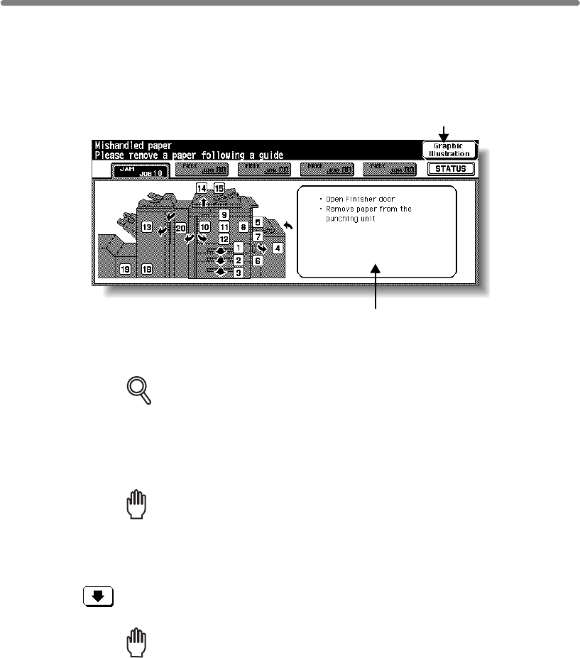
5-6
Clearing Mishandled Paper
codes display on the screen to indicate misfeed area(s). Copying operation cannot be
continued until all the misfeed locations are cleared.
DETAILS
The above screen displays all the jam numbers for the sake of explanation.
Actually a few numbers appear when a paper misfeed occurs.
1. Touch Graphic Illustration on the screen.
The screen illustrating the method for the disposal action will be displayed.
Reminder!
Before performing the clearing procedure, see p. 1-2 for the caution label
locations inside the machine.
2. Follow the procedure on the screen to remove misfed paper.
Touch on the screen, if provided, to go to the next page of a series of
illustrations.
Reminder!
When removing mishandled paper, be sure to leave no torn paper inside the
machine.
3. When completed, the Basic Screen will be restored.
If any misfeed location is left, the screen displays the next disposal procedure in the
message area and the location number in the jam position display. Repeat steps 1 to 2
until all the locations are cleared.
Paper jam position display
Numbers flashing or
lighting indicate the
jammed positions.
Message area
An action will be displayed.
Graphic Illustration key
Touch to display the subsequent
screens for the disposal action.
When a paper misfeed occurs, the mfp stops making copies and mishandled paper
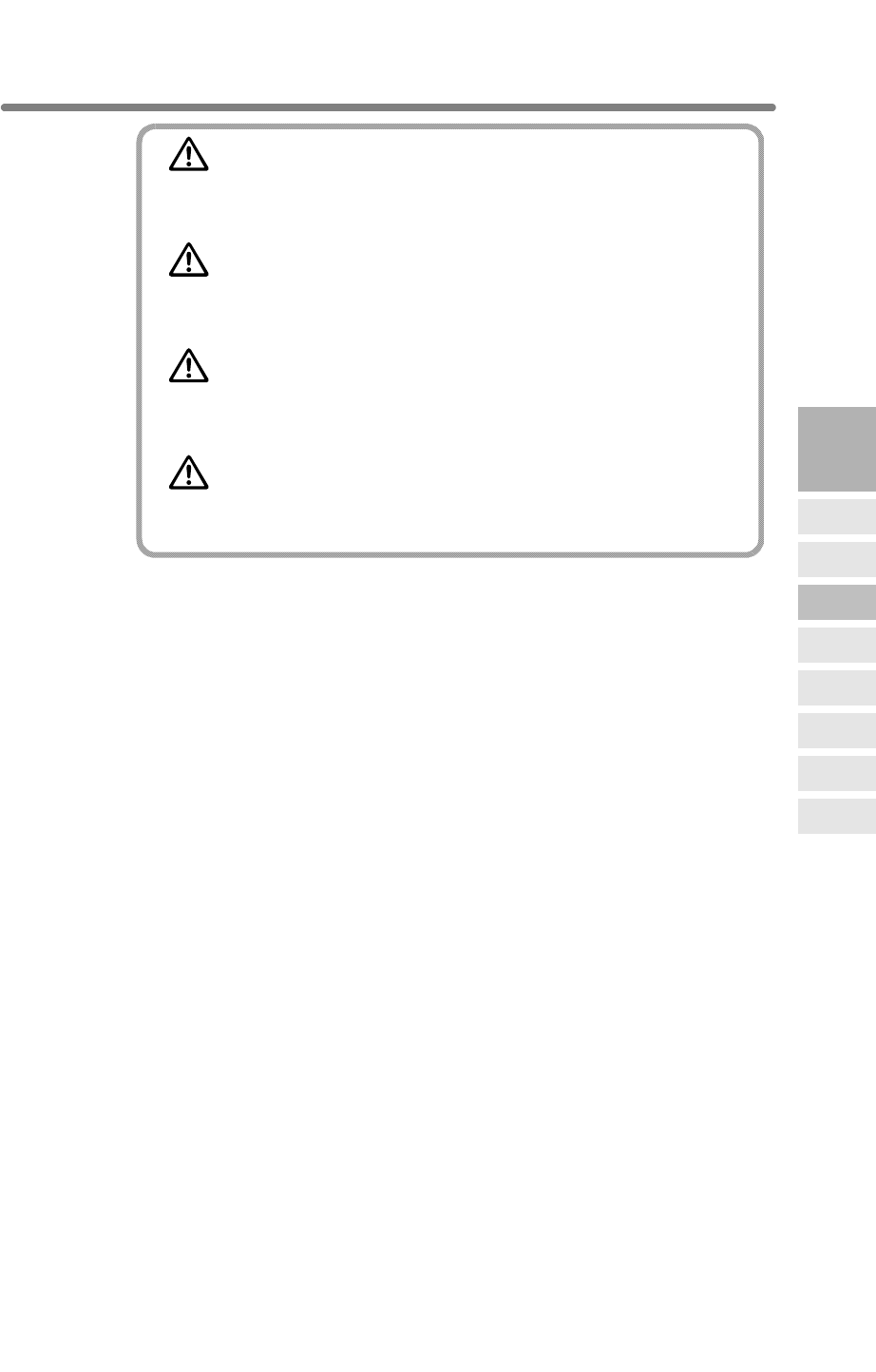
Clearing Mishandled Paper (continued)
5-7
WARNING
The drum unit generates high voltage.
To avoid bodily electrical shock, NEVER TOUCH the area.
CAUTION
The internal fixing unit is very hot.
To avoid getting burned, DO NOT TOUCH.
CAUTION
Be careful of removing staples stuck inside the machine so as
not to get injured.
CAUTION
DO NOT INSERT your finger into the two RADF hinge portions,
otherwise you may be injured.
5
Trouble-
shooting
Call for
Service
Preventive
Maintenance
Clearing
Mishandled
Paper
JAM Key
ADD PAPER
Key
Memory
Overflow
Power OFF/ON
Screen
Copying
Hints
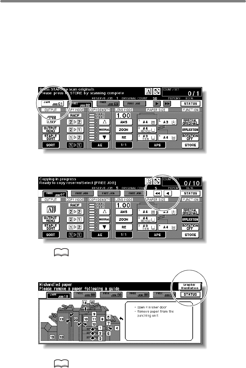
5-8
When “JAM” Appears on Folder Key (Or Arrow Key Flashes)
If a misfeed occurs with the print/scan job in progress while you are setting a reserve
job, SCAN or PRINT JOB folder key on the Basic Screen will change to flashing JAM
JOB.
When more than four jobs have been specified and the folder key of the print/scan job
in trouble is not currently displayed on the screen, the arrow key to scroll to that job will
flash.
Follow the procedure below to remove mishandled paper.
1. Display the Jam Position Screen.
Touch JAM JOB. The Jam Position Screen will be displayd.
When the arrow key flashes, touch the key to scroll to the JAM JOB folder key, then
touch it to display the Jam Position Screen.
HINT
If ADD PAPER is displayed instead of JAM JOB, see p. 5-10.
2. Touch Graphic Illustration.
The screen illustrating the method for the disposal action will be displayed.
HINT
See p. 5-6 to p. 5-7 for details on clearing procedure.
When “JAM” Appears on Folder Key (Or Arrow Key Flashes) (continued)
5-9
3. Follow the procedure on the screen to remove misfed paper.
When all procedures are completed, the Basic Screen will be restored.
DETAILS
JAM JOB has changed to STOP, and the settings for the current printing job
are displayed on the screen.
4. Press [START].
The scan/print job will resume.
5. Touch FREE JOB to continue the reserve job setting.
WARNING
The drum unit generates high voltage.
To avoid electrical shock, NEVER TOUCH the area.
CAUTION
The internal fixing unit is very hot.
To avoid getting burned, DO NOT TOUCH.
CAUTION
Be careful of removing staples stuck inside the machine so as
not to get injured.
CAUTION
DO NOT INSERT your finger into the two RADF hinge portions,
otherwise you may be injured.
5
Trouble-
shooting
Call for
Service
Preventive
Maintenance
Clearing
Mishandled
Paper
JAM Key
ADD PAPER
Key
Memory
Overflow
Power OFF/ON
Screen
Copying
Hints
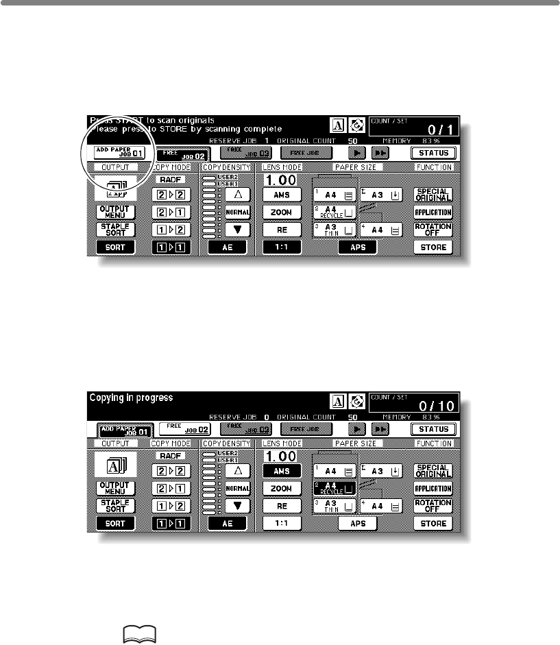
5-10
When “ADD PAPER” Appears on Folder Key (Or Arrow Key Flashes)
If the paper supply for a print job in progress becomes depleted while you are setting a
reserve job, PRINT JOB on the Basic Screen will change to flashing ADD PAPER.
When more than four jobs have been specified and the folder key of the print job in
trouble is not currently displayed on the screen, the arrow key to scroll to that job will
flash.
Follow the procedure below to continue the copying operation.
1. Display the Basic Screen for the print job in progress.
Touch ADD PAPER. The Basic Screen for the print job will be displayed.
When the arrow key flashes, touch the key to scroll to the ADD PAPER folder key,
then touch it to display the Basic Screen for the print job.
2. Check the flashing tray key, then supply that empty tray with copy
paper.
When paper supply is completed, ADD PAPER changes to STOP.
HINT
See p. 2-23 to p. 2-30 for details on loading paper.
3. Press [START].
The print job will resume.
4. Touch FREE JOB to continue the reserve job setting.

5-11
When “Memory Full” Message Is Displayed (Memory Overflow)
smooth flowing. Occasional memory overflow may occur if the installed memory is
inadequate for the copy conditions selected.
To handle the Memory overflow condition while performing a job, take the appropriate
action described below. These actions enable you to continue the job or suspend the
job.
DETAILS
Should memory overflow occur frequently, it is recommended that you
contact your service representative to extend the memory capacity in your
machine.
Memory Overflow in Current Job
When memory overflow occurs while scanning the first job, the machine stops
immediately, and the screen provides JOB STOP and SCAN STOP as the only two
available options.
DETAILS
If the job settings include Booklet mode, SCAN STOP will disappear.
• To delete all the scanned data and discontinue the job, touch JOB STOP.
• To give up further scanning but print out all the data already scanned into memory,
touch SCAN STOP.
5
Trouble-
shooting
Call for
Service
Preventive
Maintenance
Clearing
Mishandled
Paper
JAM Key
ADD PAPER
Key
Memory
Overflow
Power OFF/ON
Screen
Copying
Hints
In certain modes, this printer/mfp uses memory to make operations convenient and
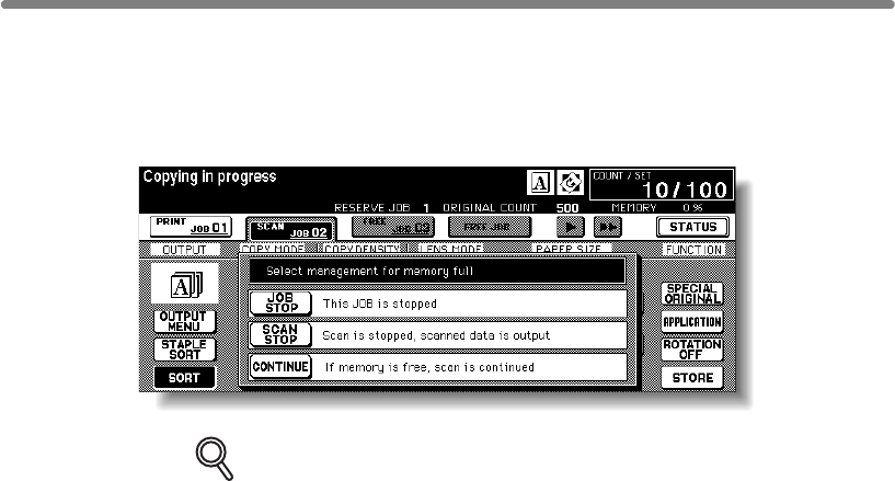
When “Memory Full” Message Is Displayed (Memory Overflow) (continued)
5-12
Memory Overflow in Reserve Job
When memory overflow occurs during the reserve operation, CONTINUE also appears
on the active screen. In this case, the machine will not stop until all the jobs on standby
for printing are completed.
DETAILS
If the job settings include Booklet mode, SCAN STOP will disappear.
• To delete the scanned data and discontinue the last reserve job, touch JOB STOP.
• To give up further scanning but print out the data already scanned for the last reserve
job, touch SCAN STOP.
• To continue scanning the last reserve job, touch CONTINUE as the current printing
job gradually enables memory for new data.
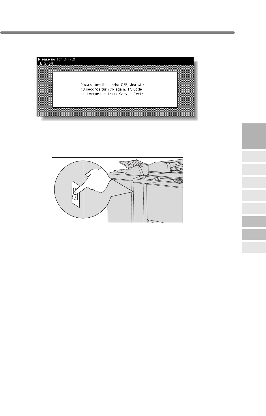
5-13
When Power OFF/ON Screen Is Displayed
will be displayed.
Follow the procedure below to turn the machine power off then on.
1. Turn OFF the power switch.
2. Wait about 10 seconds.
3. Turn ON the power switch.
5
Trouble-
shooting
Call for
Service
Preventive
Maintenance
Clearing
Mishandled
Paper
JAM Key
ADD PAPER
Key
Memory
Overflow
Power OFF/ON
Screen
Copying
Hints
When any trouble affects the electrical signal of the mfp, the Power OFF/ON Screen

5-14
Troubleshooting Tips
Fully insert paper trays.
Close Front doors.
Close Finisher door.
Check to be sure reset switch is ON.
Check to be sure power plug is firmly inserted in electrical socket.
COPY IMAGE IS TOO LIGHT
Manually adjust copy density to darker density.
Check toner indicator and add toner, if required.
Check to see if Photo, Text, or Increase Contrast mode is required.
Check the Density shift.
COPY IMAGE IS TOO DARK
Manually adjust copy density to lighter density.
Check to see if Photo, Text, or Increase Contrast mode is required.
Check the Density shift.
COPY IMAGE IS NOT CLEAN OR SHOWS SPOTS
Use clean originals since dirt marks may be copied.
Keep platen glass and inner surface of document cover clean.
Call for service if “Call for service” is displayed in the message area.
Check density indicator and lighten if required.
COPY PAPER MISHANDLES DURING COPYING
Fan copy paper and load it with curl side in proper location. Do not exceed the tray
capacity.
COPY IMAGE CAN BE RUBBED OFF
Check copy paper thickness. Use Thick paper mode, if paper weight requires it.
MAGNIFICATION CANNOT BE CHANGED
Reduce & Shift is incompatible with magnification.
Press [AUTO RESET] and set desired copying conditions without using Reduce & Shift.
DUPLEX MODES CANNOT BE SELECTED
COPYING DOES NOT BEGIN AFTER PRESSING [START]
Insert or adjust the appropriate paper tray for paper size selected.
Close Front doors completely.
Close Finisher door completely.
Check to see if the message “Please close stacker cover of Trimmer” is displayed. Close
Trimmer stacker cover or front door completely.
COPYING DOES NOT RESUME AFTER MISHANDLED PAPER IS REMOVED
COPY QUALITY IS POOR
Check paper for dampness, and replace it if necessary.
Close RADF.
Fully close RADF, then select Duplex mode again.
Close RADF firmly.
mfp DOES NOT OPERATE WHEN POWER SWITCH IS ON
Check paper for dampness. Do not leave paper in mfp when humidity is high.
Check mfp diagram on touch screen for additional indications of mishandled paper.

Troubleshooting Tips (continued)
5-15
THE ORIGINAL PAPER IS MISHANDLED OR SKEWED IN THE DOCUMENT
FEEDER
Originals should conform to the recommended size and weight.
Be sure originals are not stapled.
Check to make sure paper guides meet the width of mixed size originals.
COPY IMAGE IS SKEWED WHEN BYPASS IS USED
Be sure copy paper is inserted straight.
USING ECM, COPIES CANNOT BE MADE AFTER PASSWORD IS ENTERED
Check to see if the message EXCEEDS LIMIT is displayed.
Contact Key Operator to reset limit.
FINISHER DOES NOT OPERATE
Touch OUTPUT MENU.
Check for a paper misfeed and remove it, as required. Properly close finisher door.
ADD TONER MESSAGE IS DISPLAYED
New toner supply is needed. Follow instructions for adding toner.
CALL FOR PM IS DISPLAYED IN MESSAGE AREA
Contact your service representative for Preventive Maintenance.
APS SELECTS THE WRONG PAPER SIZE
Paper guides must be adjusted exactly to the size of originals.
IN MIXED ORIGINAL MODE, A MESSAGE TO LOAD A REQUIRED PAPER SIZE
DISPLAYS, EVEN THOUGH THAT SIZE IS LOADED IN ONE OF THE TRAYS
Paper sizes loaded in the trays must be consistent with the tray position size;
otherwise, the tray key on the Basic Screen will blink.
THE BASIC SCREEN DOES NOT DISPLAY SETTINGS AS DESCRIBED IN
INSTRUCTION MANUAL
Check with the Key Operator, as Initial Settings may have been changed.
“PLEASE CHECK ORIGINAL”
platen glass.
Select paper size and press [START]. 1.00 magnification will be selected automatically.
If this message continues to display after selecting paper size, select 1.00
magnification, even if it is already indicated, then press [START]. If desired, ask your
service representative to enable the machine to default to 1.00 magnification in this
situation.
5
Trouble-
shooting
Call for
Service
Preventive
Maintenance
Clearing
Mishandled
Paper
JAM Key
ADD PAPER
Key
Memory
Overflow
Power OFF/ON
Screen
Copying
Hints
Align originals evenly in the RADF.
RADF INDICATOR WILL NOT LIGHT AFTER [AUTO RESET] IS PRESSED
The document feeder is ready to accept originals.
Fully close RADF.
Insert originals on RADF tray, press [AUTO RESET], then [START].
RADF LIGHT IS FLASHING
This message displays when the mfp detects a non-standard paper size on the

Troubleshooting Tips (continued)
5-16
SHEET INSERTION RESULT IS NOT AS EXPECTED
Blank insertion: Be sure manuscript originals do not already include blank sheets in the
locations designated for sheet insertion.
Copy insertion: To ensure that chapter sheets in 1-2 mode always appear on the right
hand side in the finished set, insertion sheets must be designated on the page setting
screen with odd numbers, not even. If required, make an even numbered original page
odd by inserting a blank sheet in front of that page, so that the blank sheet is even and
the insertion sheet is odd.
FINISHER STAPLE RESULT IS NOT AS EXPECTED
The 2 staple position functions only on copy paper that is loaded vertically (portrait
style).
COPIES SKEW IN THE STAPLED SETS
Check to see if copy paper is excessively curled in the tray.
Reload the copy paper upside down.
USING PUNCH, COPIES CANNOT BE PUNCHED
Check to see if the message “Waste basket of Punching unit is full” is displayed.
Empty the waste basket.
COPIES CANNOT BE STAPLED OR PUNCHED IN POSITION
Check to make sure the side guide plates are securely aligned to the copy paper in the
paper tray to be used.
USING TRIMMER, COPIES CANNOT BE TRIMMED
Check to see if the message “Waste basket of Trimmer is full” is displayed.
Empty the waste basket.

6
Machine Specifications
Option Specifications.......................................................................... 6-3
6
Machine
Specifications
Engine & Option Specifications
Engine Specifications.............................................................................. 6-2

6-2
Name:
Type: Console type
Transfer method: Indirect electrostatic method
Platen glass: Fixed
Light-sensitive unit: OPC
Light source: Xenon lamp
Developing method: Dry, 2-component magnetic brush developing
Fixing method: Heat roller
Automatic and manual (9 steps)
Magnification ratio: 1:1±1.0%
Enlargement: 1:1.150 (115%), 1:1.220 (122%), 1:1.410 (141%),
1:2.000 (200%)
Reduction: 1:0.860 (86%), 1:0.820 (82%), 1:0.710 (71%), 1:0.500
(50%)
Zoom/Special ratio magnification ratio: 25% to 400% in 1%
increments
Copy paper: Plain paper: 50 to 200g/m
2
Special paper: OHP film, Labels, Tab, 3-hole
Copying speed: 85 copies/min. (A4), 66 copies/min. (A4R), 50 copies/min. (A3), 85
copies/min. (B5), 56 copies/min. (B4), 74 copies/min. (B5R)
Continuous copying: 1 to 9,999 copies
Types of original: Sheet, book originals
Original size: A3 maximum
Copy size: Standard size: A3 to A6 size (image cutoff width: leading and trailing
ends 2mm±2mm, top and bottom 1.5mm±1.5mm)
Wide size and non-standard size: Max. 314mm x 459mm
Paper supply method: Tray 1, 2 (universal); 500 sheets (80g/m
2
)
Tray 3 (universal); 1,000 sheets (80g/m
2
)
2
2
Warm-up time: Approx. 6 minutes
First copy time: Approx. 3.3 seconds (A4)
Power: AC 230V/50Hz (This equipment selects the correct voltage
automatically.)
Power consumption: 3.45KW max. (with option)
Sound power level: 78dB max. (with option)
Weight:
Size:
Effective size*:
*Effective size is dimensions required when the Multi-sheet bypass tray is opened.
These specifications are subject to change without notice.
Multi-sheet bypass tray; 150 sheets (80g/m )
Q3637A)
Q3224A + Q3638A)
Q3222A/Q5684A/Q3223A/Q5685A + Q3224A + Q3638A)
hp 9085mfp
Engine Specifications
Engine
Approx. 280kg (engine + RADF)
887(W) x 775(D) x 1160(H) mm (engine + RADF)
1816(W) x 775(D) x 1160(H) mm (engine + RADF + Q3219A +
3177(W) x 775(D) x 1160(H) mm (engine + RADF + Q3220A +
3351(W) x 775(D) x 1160(H) mm (engine + RADF + Q3220A +
1311(W) x 865(D) mm (engine + RADF)
2177(W) x 865(D) mm (engine + RADF + Q3220A + Q3637A)
Contrast adjustment:
Tray 4 (HCI) (fixed); 4,000 sheets (80g/m ) (Q3637A/Q3638A option)

6-3
Option Specifications
Function: Feeds 1- and 2-sided originals automatically
Type of original: Plain paper (50 to 200g/m
2
)
(50 to 200g/m
2
using SDF mode in simplex scanning)
Original size: A3, B4, F4, A4, A4R, B5, B5R, A5, A5R, 11”x17”, 8.5”x11”
Original capacity: 100 sheets max. (80g/m
2
)
Original insertion: Automatic feed at a time
Dimensions: 650(W) x 570(D) x 170(H) mm
Weight: Approx. 21.5kg
Power source:
Type: Offset catch tray
Sorting system: Sorting by shifting (30±2 mm) (copies are delivered face down)
Paper sizes: A3, B4, F4, A4R, A4, B5R, B5, A5, B6, 11”x17”, 8.5”x14”, 8.5”x11”,
8.5”x11”R, 5.5”x8.5” (50 to 200g/m
2
paper)
Number of stapled sheet:
2
2
Staple cartridge: 5,000 staples
Dimensions: 544(W) x 656(D) x 1095(H) mm
Weight:
Power source:
Function:
Types of paper: Normal: 60 to 90g/m
2
paper
Special: OHP film, thin/thick paper (50 to 59g/m
2
, 91 to 200g/m
2
paper)
Paper sizes: A3, B4, F4, A4R, A4, B5, A5
Stack capacity: 200 sheets max. or 40 mm or less (200g/m
2
paper)
Dimensions: 330(W) x 456(D) x 120(H) mm
Weight: Approx. 5kg)
Power source: Supply from finisher
Function: Trimming the end of booklet
Types of paper: 60 to 90g/m
2
paper
One cover paper only (91 to 200g/m
2
paper)
Paper sizes: A3, B4, A4R, 8.5”x11”R
Number of trimmed sheet: 3 sheets max. in Fold mode
16 sheets max. using 80g/m
2
paper only in Stitch&Fold mode
15 sheets max. with a cover in Stitch&Fold mode
Trimming width: 10mm max.
Stack capacity: Approx. 512 sheets max.
100 sets max of 2~5-sheet-folded booklet (500 sheets max.)
50 sets max. of 6~10-sheet-folded booklet (500 sheets max.)
32 sets max. of 11~16-sheet-folded booklet (512 sheets max.)
Dimensions: 1117(W) x 604(D) x 562(H) mm
Weight: Approx. 68kg
Power source:
These specifications are subject to change without notice.
6
Machine
Specifications
Q3219A/Q3220A In-Bin Stapler Finisher
Approx. 65kg (Q3219A) / 80kg (Q3220A)
Q3221A Cover Sheet Feeder
Paper feed into Finisher Q3219A/Q3220A
Q3224A Trimmer Unit
Q3219A: 100 sheets max. or 10 mm or less (80g/m paper)
Q3220A: 50 sheets max. or 5 mm or less (80g/m paper)
RADF (Q5682A)
Supply from engine
Supply from engine
Supply from outlet (power cord required)

Option Specifications (continued)
6-4
Function: Punching file holes in copies
Hole diameter: 6.5mm ± 0.5mm
Hole pitch: 80mm ± 0.5mm
Paper sizes:
Types of paper: 50 to 170*g/m
2
paper
*Some 170g/m
2
paper types may not be punched easily.
Dimensions: 169(W) x 660(D) x 930(H) mm
Weight: Approx. 30kg
Power source:
Function: Punching file holes in copies and Z-folding the copies
Hole diameter: 6.5mm ± 0.5mm
Hole pitch: 80mm ± 0.5mm
Paper in Punch mode: A3, B4, A4, B5 (50 to 170*g/m
2
paper)
*Some 170g/m
2
paper types may not be punched easily.
Paper in Z-Folding mode: A3, B4 (60g to 90g/m
2
paper)
Folded width: 209mm or less for A3
181mm or less for B4
Dimensions: 169(W) x 660(D) x 930(H) mm
Weight: Approx. 38kg
Power source:
Function:
Paper sizes: A4, B5, 8.5”x11”, Wide sizes
Types of paper: Normal: 60 to 90g/m
2
paper
Thick: 91 to 200g/m
2
paper
Capacity: 4,000 sheets
Dimensions:
Weight: Approx. 30kg
Power source:
Function:
Paper sizes: A3, B4, F4, A4, A4R, 11”x17”, 8.5”x14”, 8.5”x11”, 8.5”x11”R, Wide
sizes
Types of paper: Normal: 60 to 90g/m
2
paper
Thick: 91 to 200g/m
2
paper
Capacity: 4,000 sheets
Dimensions: 670(W) x 639(D) x 695(H) mm
Weight: Approx. 42kg
Power source:
These specifications are subject to change without notice.
Q3222A/Q5684A Punching Unit
Q3223A/Q5685A Punching / Z-Folding Unit
Paper feed into engine
Supply from engine
Paper feed into engine
Supply from engine
Q3637A Tray 4 /HCI
Q3638A Tray 4 /HCI
430(W) x 639(D) x 690(H) mm
A3, B4, A4, B5
Supply from outlet (power cord required)
Supply from outlet (power cord required)
* NOTE: Number of holes configurable by service personnel ONLY.
* NOTE: Number of holes configurable by service personnel ONLY.
4 or 2 / 3 or 2, region dependent
4 or 2 / 3 or 2, region dependent* Number of punch holes:
* Number of punch holes:

Option Specifications (continued)
6-5
6
Machine
Specifications
These specifications are subject to change without notice.
Memory Unit
Adds connectivity and highly efficient PCL printing capability to the 9085mfp.
Print Controller Kit
Product Number: Q5681A
Product Number: C9653A
Three slots available for additional memory modules of 256MB each.
6-6
blank page

Advanced
7
8
9
10
11
13
12
Advanced
Information
Applications
Maintenance
& Supplies
Paper &
Original Info
Function
Key Operator
Mode
Special
Original
Image Store
blank page

7
7
Advanced
Information
Using Finisher
Manually
Cover Sheet
Feeding
Trimming
Z-Fold
Tandem Mode
Punch
Fold /
Stitch&Fold
Vertical/Hori-
zontal Zoom
Rotation
Weekly
Timer
Advanced Information
How to Use Advanced Functions
Programmed Shut-Off (Weekly Timer).................................................... 7-2
Rotation .............................................................................................. 7-4
Vertical/Horizontal Zoom Mode............................................................... 7-5
Making Folded Booklet (Fold / Stitch&Fold) ....................................... 7-8
Punching File Holes in Copies (Punch) .................................................7-11
Output Z-Folded Copies (Z-Fold) ..................................................... 7-14
Making Trimmed Booklet (Trimming).................................................... 7-16
Cover Sheet Feeding........................................................................ 7-19
Using Finisher Manually ....................................................................... 7-22
Using Two mfps in Tandem............................................................... 7-25
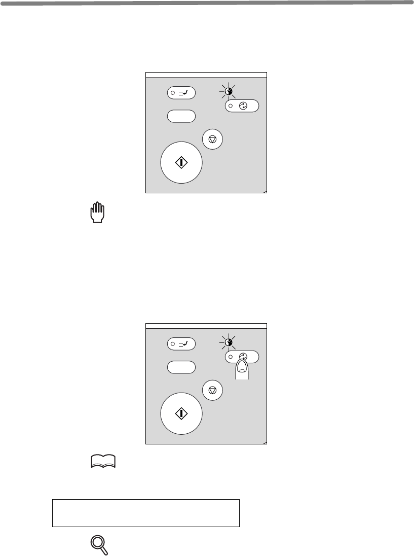
7-2
Programmed Shut-Off (Weekly Timer)
Operator.
Reminder!
AUTOMATICALLY. DO NOT TURN IT OFF BY PRESSING POWER SWITCH.
When the TIMER indicator light is on and other indicators are off, copying is unavailable
due to the Weekly Timer function.
However, copying can be available by using the following procedure.
1.
HINT
For details of the Weekly Timer function, see p. 13-27 to p. 13-35.
The Basic screen will be displayed along with the message shown below.
Timer interrupt mode
Enter password
DETAILS
The machine power will be turned off automatically after 5 minutes from this
state if a password is not entered.
INTERRUPT
PROOF COPY
TIMER
STOP
START
T
Y.
ON / OFF
INTERRUPT
PROOF COPY
TIMER
STOP
START
T
Y.
ON / OFF
This function is not factory-set. When a mfp is under control of the Weekly Timer
function, the TIMER indicator on the right side of the control panel is lit.
The Weekly Timer function turns a mfp on and off at the time specified by the Key
IMPORTANT: WHEN THE TIMER INDICATOR IS LIT, THE mfp WILL TURN OFF
SLEEP
Press [SLEEP ON/OFF] on the control panel.

Programmed Shut-Off (Weekly Timer) (continued)
7-3
The Timer Interrupt password is not factory set and must be entered by the Key Oper-
ator.
In the event the Timer Interrupt password has not been entered by the Key Operator,
the following message will display instead.
Input copy time
0 hour(s) 05 minute(s)
When the above message displays, proceed to step 4.
2. Enter the password.
Enter a 4-digit number Timer Interrupt password using the keypad on the control
panel.
HINT
For setting the Timer Interrupt password, see p. 13-35.
DETAILS
If an invalid password is entered, continue by entering the valid 4-digit
password.
3. Press [START].
The following message will be displayed on the Basic Screen.
Input copy time
0 hour(s) 05 minute(s)
4. Set the hour for the interrupt use.
Enter a 1-digit hour (ex. 3 hours is 3) using the keypad on the control panel. (0 ~ 9)
5. Press [START].
6. Set the minute for the interrupt use.
Enter a 2-digit minute (ex. 7 minutes is 07) using the keypad on the control panel. (00
~ 59)
DETAILS
Entering a number smaller than 5 will set the minute at 5.
7. Press [START].
Copying is available until the set time is up.
8.
ON/OFF] for one second or longer, then release it.
7
Advanced
Information
Using Finisher
Manually
Cover Sheet
Feeding
Trimming
Z-Fold
Tandem Mode
Punch
Fold /
Stitch&Fold
Vertical/Hori-
zontal Zoom
Rotation
Weekly
Timer
When Timer Interrupt of the mfp is finished, press [SLEEP
The mfp returns to the OFF condition and copying is again disabled.
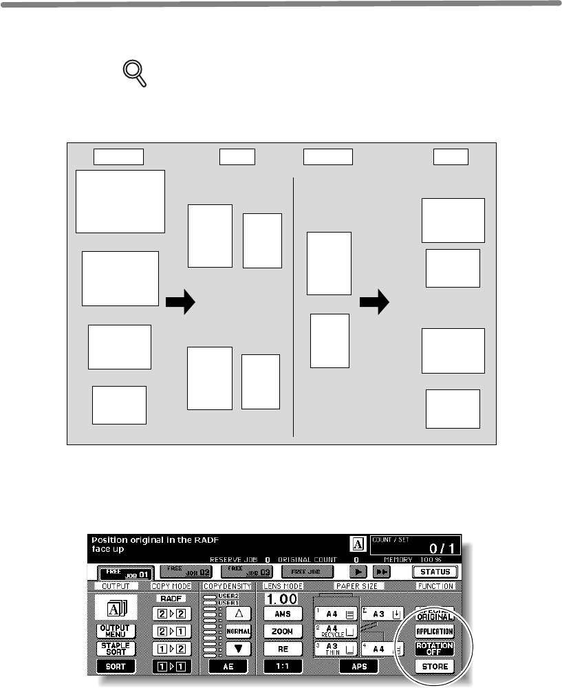
7-4
Rotation
This function allows you to utilize APS or AMS and copy the original documents onto
size A4 or B5, irrespective of the copy paper feeding direction.
DETAILS
Follow the procedure below to release/resume this function.
1. Touch ROTATION OFF on the Basic Screen to highlight it.
When Rotation is released, the Rotation icon on the Basic Screen will disappear to
indicate that this function is cancelled.
2. Touch to deselect ROTATION OFF to resume this function.
When Rotation is resumed, the Rotation icon will be displayed on the screen.
A3
B4
A4R
A4
Rotation copying Rotation copying
Normal copying
Normal copying
B5
B5R
B5R
A4R
A4 B5
A4
B5
B5R
A4R
Original Copy Original Copy
By default, Rotation requires APS or AMS to function. The Key Operator can
set this function ON, or to operate when APS, AMS or reduce functions. See
p. 13-39 to p. 13-44.
abcde
abcde
abcde
abcde
abcde
abcde
abcde
abcde
abcde
abcde
abcde abcde
abcde
abcde
The mfp is initially set to activate the Rotation function automatically.
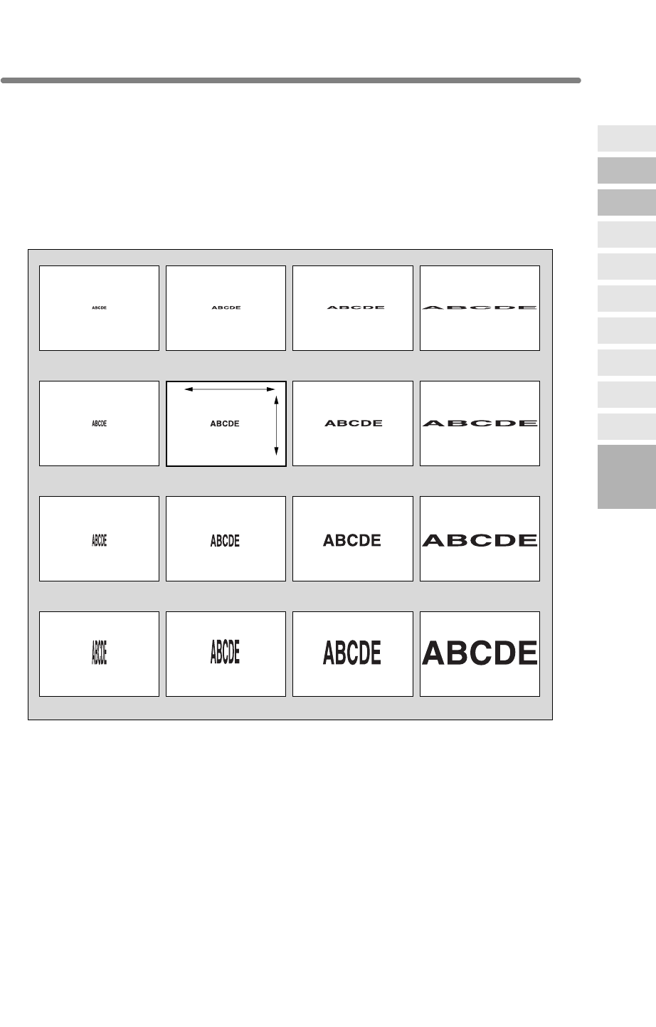
7-5
Vertical/Horizontal Zoom Mode
Use the Vertical/Horizontal zoom mode to reduce or enlarge vertical and horizontal
dimensions, independently.
>>>Vertical/Horizontal Zoom Mode Specifications<<<
❒Vertical/Horizontal zoom range: 0.25~4.00
❒Incompatible Conditions: APS, AMS, Reduce & Shift in Image Shift, Overlay with
Repeat
The figure shown below is the sample image using the Vertical/Horizontal zoom.
Length: 1.00, Width: 1.00
Length: 0.50, Width: 1.00
Length: 4.00, Width: 1.00
Length: 2.00, Width: 1.00
Length: 1.00, Width: 0.50
Length: 0.50, Width: 0.50
Length: 4.00, Width: 0.50
Length: 2.00, Width: 0.50
Length: 1.00, Width: 2.00
Length: 0.50, Width: 2.00
Length: 4.00, Width: 2.00
Length: 2.00, Width: 2.00
Length: 1.00, Width: 4.00
Length: 0.50, Width: 4.00
Length: 4.00, Width: 4.00
Length: 2.00, Width: 4.00
Length
Width
7
Advanced
Information
Using Finisher
Manually
Cover Sheet
Feeding
Trimming
Z-Fold
Tandem Mode
Punch
Fold /
Stitch&Fold
Vertical/Hori-
zontal Zoom
Rotation
Weekly
Timer
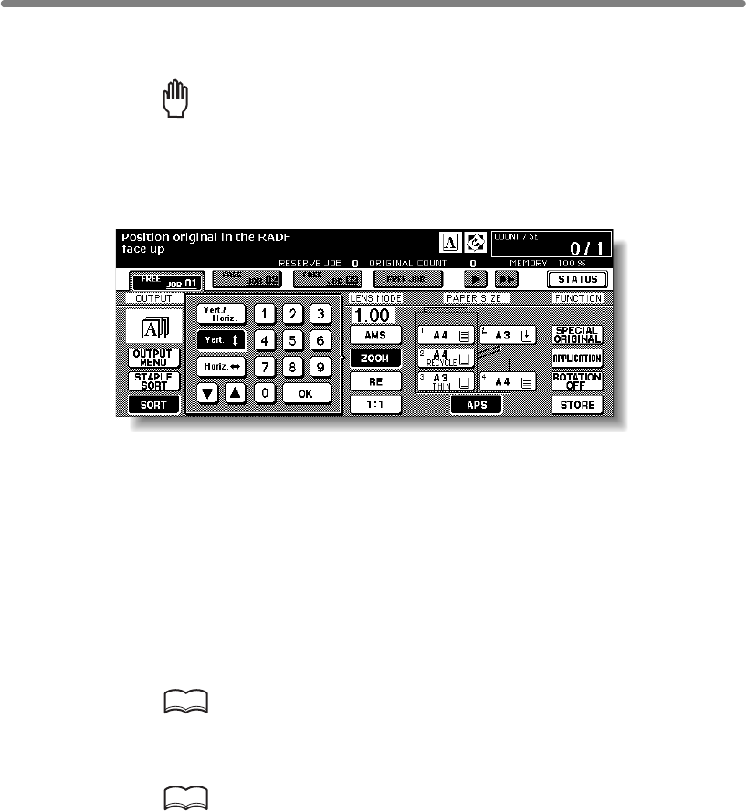
Vertical/Horizontal Zoom Mode (continued)
7-6
1. Touch ZOOM on the Basic Screen.
The popup menu for setting a zoom ratio will be displayed.
Reminder!
press [AUTO RESET].
2. Touch Vert. on the popup menu to highlight it, then set the vertical
zoom ratio.
Use the keypad on the popup menu to enter a 3-digit vertical zoom ratio, or use arrow
Similarly, touch Horiz. to highlight it, then set the horizontal zoom ratio.
3. Touch OK.
The popup menu disappears automatically and the specified zoom ratio will be
displayed on the Basic Screen.
4. Select additional copy conditions, as desired.
5. Enter the desired print quantity from the control panel keypad.
HINT
See p. 3-7 for details on setting print quantity.
6. Position original(s).
HINT
See p. 3-2 to p. 3-6 for details on positioning originals.
7. Press [START].
When starting a new copying job, be sure to close the RADF securely, then
keys (p/q) to scroll to the desired ratio.
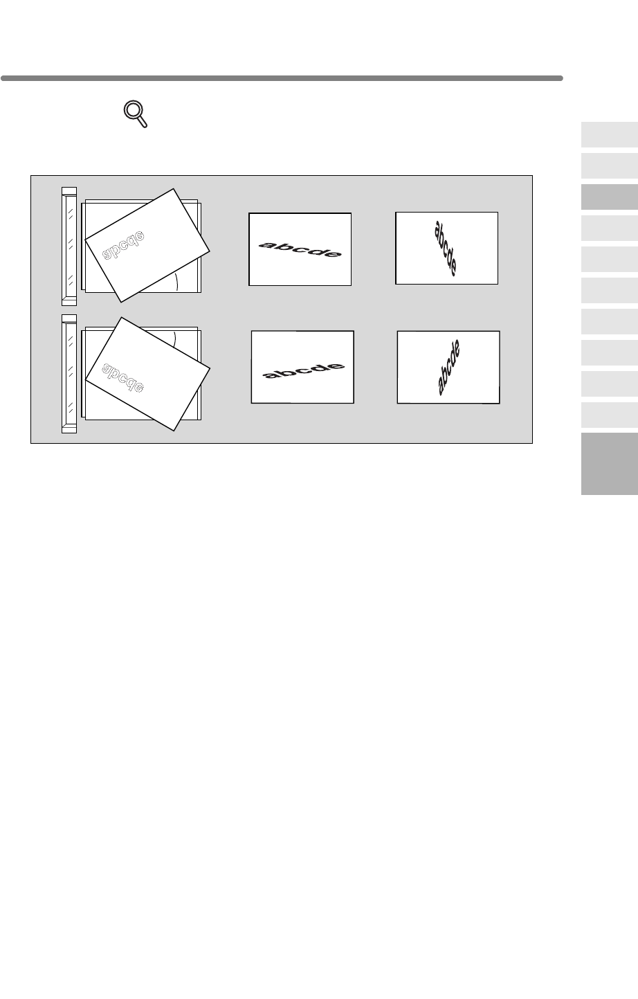
Vertical/Horizontal Zoom Mode (continued)
7-7
DETAILS
The figure shown below is the sample image using the Vertical/Horizontal
zoom with an original placed slantwise on the platen glass.
Length: 0.50, Width: 2.00 Length: 2.00, Width: 0.50
Length: 0.50, Width: 2.00 Length: 2.00, Width: 0.50
30°
30°
7
Advanced
Information
Using Finisher
Manually
Cover Sheet
Feeding
Trimming
Z-Fold
Tandem Mode
Punch
Fold /
Stitch&Fold
Vertical/Hori-
zontal Zoom
Rotation
Weekly
Timer

7-8
Making Folded Booklet (Fold / Stitch&Fold)
DETAILS
• When copying two-sided signature originals using the Fold or Stitch &
Fold mode, release the automatically selected Booklet mode on the
Application Selection Screen.
• When copying dark originals or using Reverse Image mode together with
Fold or Stitch & Fold mode, the folded line of the output copies may be
slightly shifted.
The following copy results may be expected when using Fold or Stitch & Fold mode:
In the Fold mode, each copied set is folded and output to the Booklet tray of the Finisher.
In the Stitch & Fold mode, each copied set is stapled at two positions (saddle stitched),
then folded and output to the Booklet tray of the Finisher.
>>>Specifications for Fold / Stitch & Fold Mode<<<
❒Max. number of folded sheets (80 g/m2 paper) in both modes:
Fold: 3 sheets (less than in Stitch & Fold mode because they are not
clinched first)
Stitch & Fold: 20 sheets
19 sheets when using thick cover paper
❒Paper size: A3, B4, A4R
❒Booklet tray capacity:
When the Booklet tray capacity is exceeded, the Finisher will stop operating. Select
the appropriate print quantity by referring to the following capacities.
Approx. 100 sheets max.
Fold: 33 sets max. of 3-sheet-folded booklet (33 x 3 = 99 sheets)
Stitch & Fold: 20 sets max. of 5-sheet-folded booklet (20 x 5 = 100 sheets)
5 sets max. of 20-sheet-folded booklet (5 x 20 = 100 sheets)
Rotation sort, Rotation group, Output to Secondary (sub) tray, Trimming, Punch, Mixed
Original, Full Area in Non STD size, Tab Paper, Sheet/Cover Insertion, Combination, OHP
Interleave, Program Job, Non-Image Area Erase, Reverse Image, Repeat
❒
Incompatible conditions without Booklet: Sort, Staple-sort, Group, Rotation Sort, Rotation
Group, Output to Secondary (sub) tray, Trimming, Punch, OHP Interleave, Reverse Image
3 sheets max. 20 sheets max.
19 sheets max. when using thick cover paper
Fold Stitch & Fold
The Fold and Stitch & Fold modes are available only when the Q3220A Finisher
optionis installed. When either mode is selected, the Booklet feature is automatically
selectedand indicated on the Application Selection Screen.
❒
Incompatible Conditions with Booklet selected: APS, 1u1, 2u1, Sort, Staple-sort, Group,
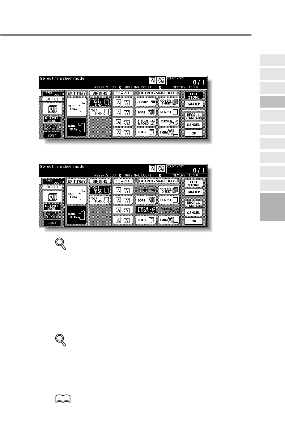
Making Folded Booklet (Fold / Stitch&Fold) (continued)
7-9
1. Touch OUTPUT MENU on the Basic Screen
The Output Mode popup menu will be displayed.
2. Touch MAIN TRAY, if not highlighted.
3. Touch STITCH & FOLD or FOLD, as desired.
DETAILS
Selecting FOLD or STITCH & FOLD will automatically switch the output tray
to Booklet tray. Notice that the arrow pointing on the MAIN TRAY key shifts
from the Main tray to the Booklet tray.
When selecting STITCH & FOLD, the machine with the trimmer unit installed selects
TRIM automatically. To cancel the trimming mode, touch TRIM to deselect it.
4. Touch OK on the Output Mode popup menu.
The Basic Screen will be restored and the selection made in the output mode will be
reflected in the OUTPUT icon area.
5. Select additional copying features, as required.
DETAILS
NO COVER SHEET of the Booklet is initially selected.
To change this selection, touch APPLICATION on the Basic Screen to
display the Application Selection Screen, then touch Booklet twice to
display the Booklet Mode Selection Screen to make another selection or to
release the setting.
6. Enter the desired print quantity from the control panel keypad.
HINT
See p. 3-7 for details on setting print quantity.
7
Advanced
Information
Using Finisher
Manually
Cover Sheet
Feeding
Trimming
Z-Fold
Tandem Mode
Punch
Fold /
Stitch&Fold
Vertical/Hori-
zontal Zoom
Rotation
Weekly
Timer
Making Folded Booklet (Fold / Stitch&Fold) (continued)
7-10
7. Position original(s).
HINT
See p. 3-2 to p. 3-6 for details on positioning originals.
DETAILS
When loading originals, heed the following limits on capacity:
Fold mode:
12 pages or less for simplex copying
6 pages or less for duplex copying
Stitch & Fold mode:
80 pages or less for simplex copying
40 pages or less for duplex copying
Exceeding the above capacity limits may cause trouble in the Finisher.
8. Press [START].
CAUTION
When the Booklet tray capacity is exceeded, the Finisher will
cease operating. To avoid this, select the appropriate print
quantity from the specifications shown on p. 7-8.
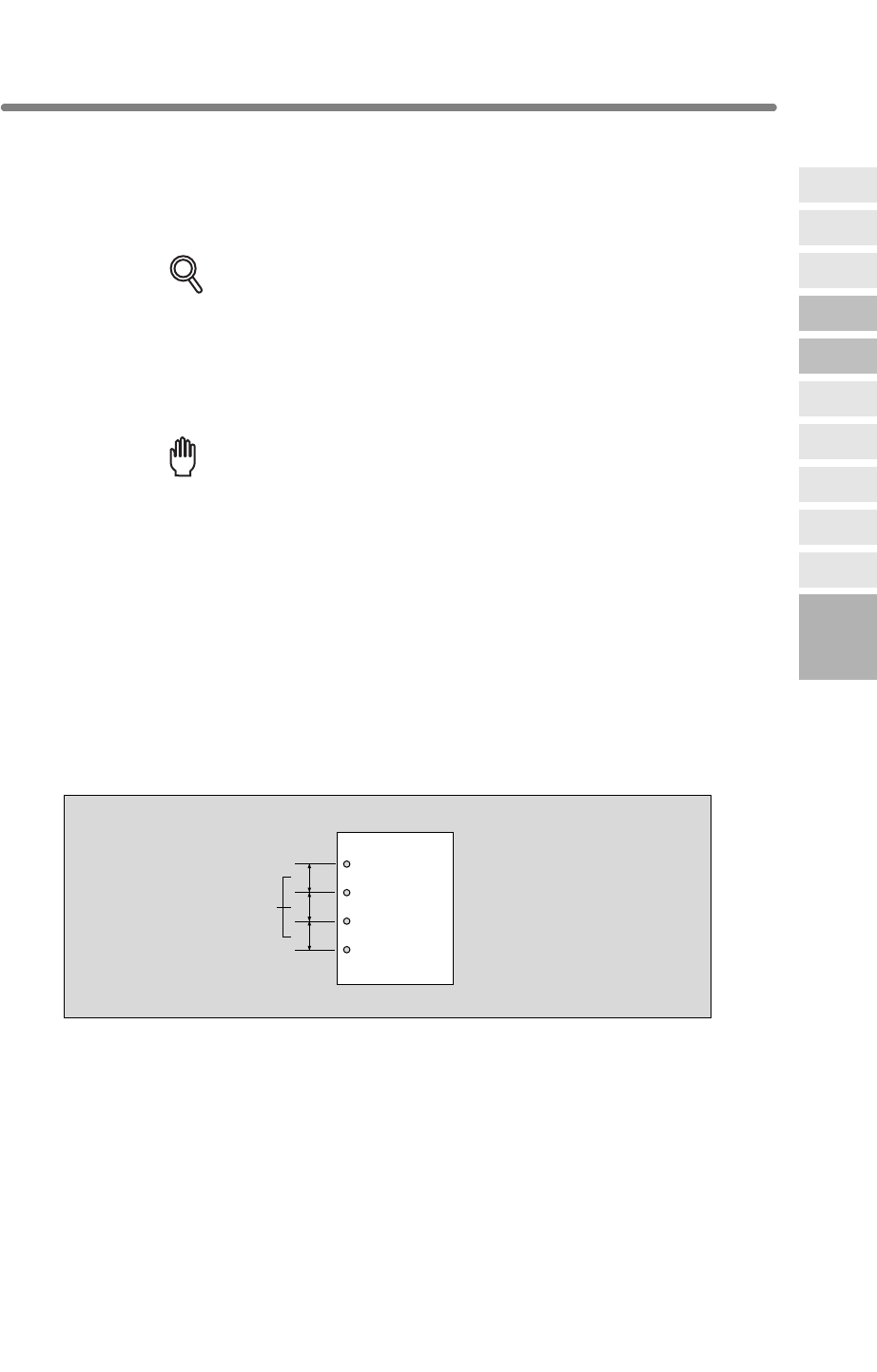
7-11
Punching File Holes in Copies (Punch)
When the Punch mode is selected in combination with any of the Primary (Main) tray
output modes, each copied sheet is punched and output to the Primary tray according
to the selected output mode.
DETAILS
• Some staple positions previously selected may conflict with this function.
• Special size paper (STD size (special), Non STD size, Wide size) cannot
be punched.
•
• If the ATS (Automatic Tray Switching) functions while the machine uses
the Punch mode, the punch holes may be slightly off the appropriate
positions.
Reminder!
• Do not punch special paper type such as transparent films, labels, tabbed
sheets, etc. Otherwise, machine trouble may occur in Punching unit.
• Be sure that the side guide plates of the paper tray are securely aligned
to the paper; otherwise the copies may not be punched in position.
>>>Specifications for Punch Mode<<<
❒Copy paper size: A3, B4, A4, B5 (80 g/m2 paper recommended)
❒Paper weight: 60 ~ 90 g/m2
Thin paper: 50 ~ 59 g/m2
Thick paper: 91 ~ 170* lb * Some 170 g/m2 paper types may not be punched easily.
❒Hole diameter: 6.5 mm ± 0.5 mm
❒Hole pitch: 80 mm ± 0.5 mm
❒Incompatible Conditions: Using platen glass (available when using Platen store
mode), Fold, Stitch & Fold, Trimming, Output to Secondary (sub) tray, Mixed Original
(A4R, B5R, A5, A5R mixed), Non STD Size, Booklet, OHP Interleave
80mm
7
Advanced
Information
Using Finisher
Manually
Cover Sheet
Feeding
Trimming
Z-Fold
Tandem Mode
Punch
Fold /
Stitch&Fold
Vertical/Hori-
zontal Zoom
Rotation
Weekly
Timer
The Punch mode is available only when the Q3222A/Q5684A Hole Punching unit or
Q3223A/Q5685A Hole Punching/Z-Folding unit option is installed on the
Q3219A/Q3220A Finisher.
The HCI specified as Thick 3 cannot be used.
❒Number of holes: 4 or 2 / 3 or 2, region dependent
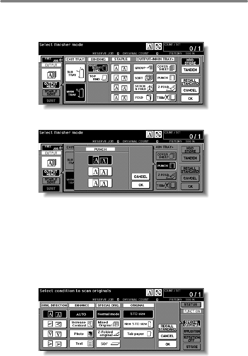
Punching File Holes in Copies (Punch) (continued)
7-12
1. Touch OUTPUT MENU on the Basic Screen
The Output Mode popup menu will be displayed.
2. Touch MAIN TRAY, if not highlighted.
3. Touch PUNCH.
The Punch Position popup menu will be displayed.
4. Touch the desired punch position key on the screen to highlight it.
5. Touch OK on the Punch Position popup menu to restore the Output
Mode popup menu.
6. Touch OK on the Output Mode popup menu to complete the setting
and return to the Basic Screen.
The selection made in punch position will be displayed in the OUTPUT icon area.
7. Specify the original set direction.
Touch SPECIAL ORIGINAL on the Basic Screen to display the Special Original popup
menu.
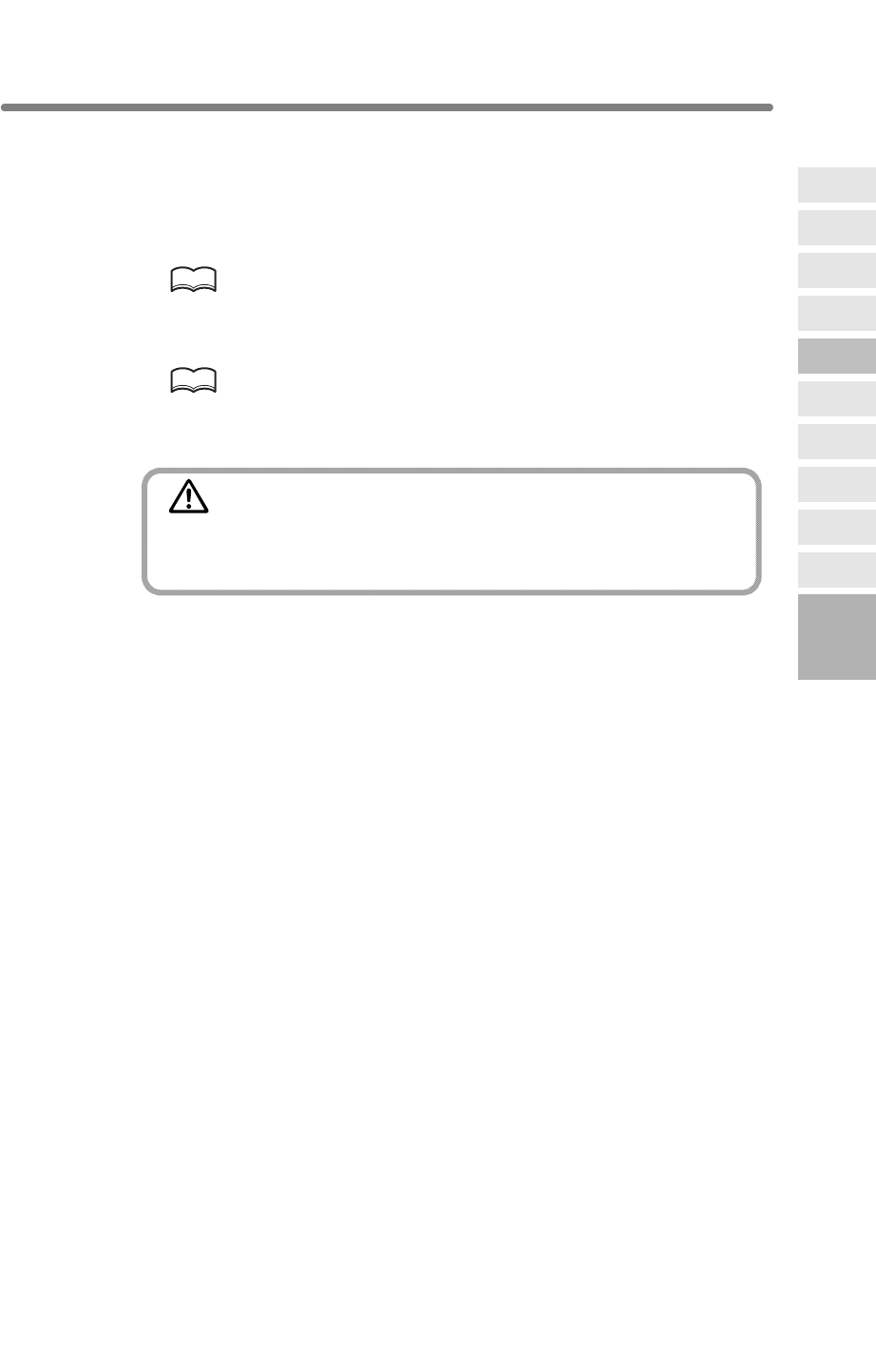
Punching File Holes in Copies (Punch) (continued)
7-13
Touch to select the desired original set direction, then touch OK to return to the Basic
Screen.
8. Select additional copying features, as required.
9. Enter the desired print quantity from the control panel keypad.
HINT
See p. 3-7 for details on setting print quantity.
10. Position originals in the document feeder.
HINT
See p. 3-2 to p. 3-5 for details on positioning originals.
11. Press [START].
CAUTION
When the finisher exit tray capacity is exceeded due to the print
quantity selected, remove the copied sets as they exit;
otherwise, mishandled paper will occur.
7
Advanced
Information
Using Finisher
Manually
Cover Sheet
Feeding
Trimming
Z-Fold
Tandem Mode
Punch
Fold /
Stitch&Fold
Vertical/Hori-
zontal Zoom
Rotation
Weekly
Timer
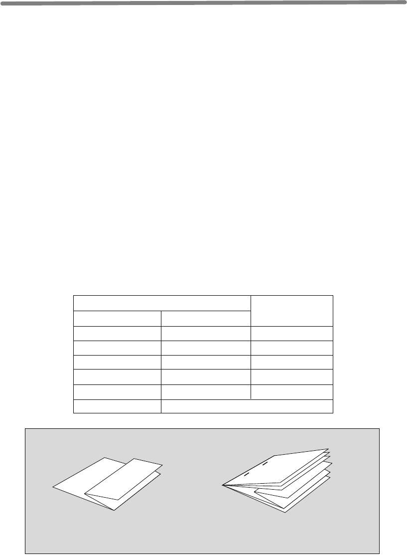
7-14
Output Z-Folded Copies (Z-Fold)
When the Z-Fold mode is selected in combination with any of the Primary (main) tray
output modes, the original image is copied on A3/B4 copy paper and output to the
Primary (main) tray of the Finisher according to the selected output mode.
>>>Specifications for Z-Fold Mode<<<
❒Folding type:Z-folding
❒Copy paper size:A3, B4 (60 ~ 90 g/m2 paper)
All other paper sizes will be output without Z-fold or double-fold.
❒Folded width*: 209 mm or less for A3
181 mm or less for B4
*The width from the paper edge to the first folded line
❒
When using Mixed Original mode with Z-Fold mode, A3 and B4 originals should not
be mixed, otherwise the Z-Fold mode may not function properly.
❒Special paper type (Thick 2, OHP film, labels, tabbed sheets) and non-standard size
(STD size (special), Non STD size, Wide paper) cannot be Z-folded. Using special
paper willl cause the machine trouble.
Some plain paper types may cause folded line to shift in Z-Fold mode.
❒Incompatible Conditions: Using platen glass (available when platen memory copy is
selected), Staple-sort using B4, Output to Secondary (sub) tray, Fold, Stitch & Fold,
Trimming, Tandem mode, OHP Interleave
❒When using Z-fold, Staple-sort and APS for mixed size originals, heed the following
limits on capacity:
1 sheet
2
3
4
5
6 or more
1 ~ 40 sheets
0 ~ 30
0 ~ 20
0 ~ 10
0
20 stapled sets
10
4
3
2
Primary Tray Capacity
Capacity for one stapled set
Number of Z-folded sheets
Number of regular sheets
Staple-Sort is unavailable with Z-Folding.
Capacity for Mixed Size Originals
using Z-Folding and Staple-Sort with APS
Z-Folding Z-Folding + Staple-sort
+ APS with Mixed Original
The Z-Fold mode is available only when Q3223A/Q5685A Hole Punching/Z-
Folding unit option is installed on the Q3219A/Q3220A Finisher.
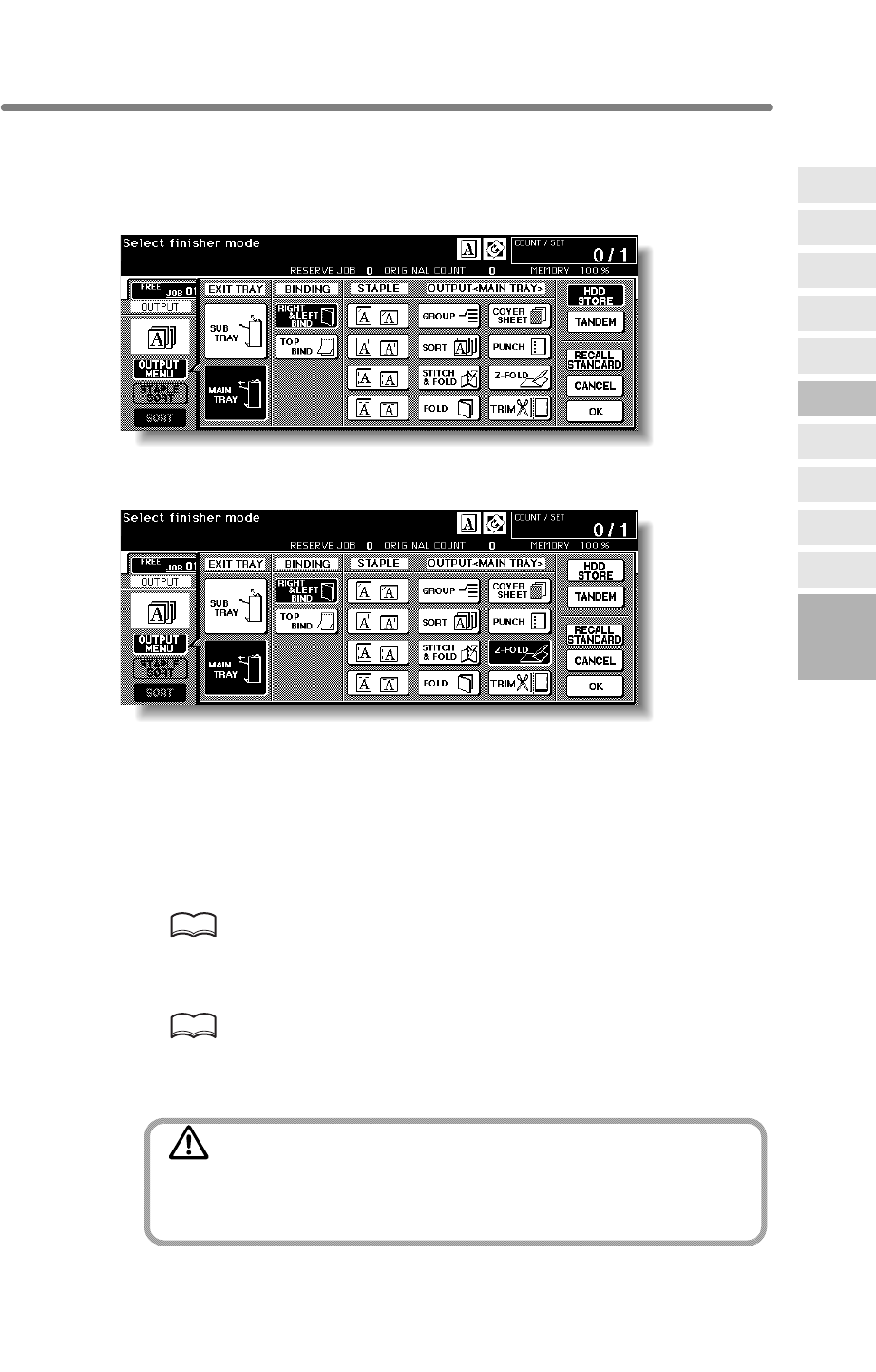
Output Z-Folded Copies (Z-Fold) (continued)
7-15
1. Touch OUTPUT MENU on the Basic Screen
The Output Mode popup menu will be displayed.
2. Touch MAIN TRAY, if not highlighted.
3. Touch Z-FOLD to highlight it.
5. Touch OK on the Output Mode popup menu to complete the setting
and return to the Basic Screen.
The Z-Fold icon will be displayed in the OUTPUT icon area.
6. Select additional copying features, as required.
7. Enter the desired print quantity from the control panel keypad.
HINT
See p. 3-7 for details on setting print quantity.
8. Position originals.
HINT
See p. 3-2 to p. 3-6 for details on positioning originals.
9. Press [START].
CAUTION
When the finisher exit tray capacity is exceeded due to the print
quantity selected, remove the copied sets as they exit;
otherwise, mishandled paper will occur.
7
Advanced
Information
Using Finisher
Manually
Cover Sheet
Feeding
Trimming
Z-Fold
Tandem Mode
Punch
Fold /
Stitch&Fold
Vertical/Hori-
zontal Zoom
Rotation
Weekly
Timer
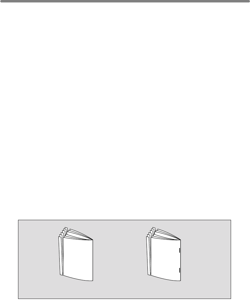
7-16
Making Trimmed Booklet (Trimming)
>>>Specifications for Trimming Mode<<<
❒Max. number of folded sheets (80 g/m2 paper) in both modes:
Fold and Trimming: 3 sheets
Stitch & Fold and Trimming: 16 sheets
15 sheets when using thick cover paper
❒Paper size: A3, B4, A4R (60 ~ 90 g/m2 paper)
❒Trimmer unit tray capacity:
When the Trimmer unit tray capacity is exceeded, the Finisher and Trimmer unit will
stop operating. Select an appropriate print quantity by referring to the following
capacities.
Approx. 512 sheets max.
Fold and Trimming: 100 sets max. of 3-sheet-folded booklet
(100 x 3 = 300 sheets max.)
Stitch & Fold and Trimming: 100 sets max. of 2~5-sheet-folded booklet
(100 x 5 = 500 sheets max.)
50 sets max. of 6~10-sheet-folded booklet
(50 x 10 = 500 sheets max.)
32 sets max. of 11~16-sheet-folded booklet
(32 x 16 = 512 sheets max.)
Group, Rotation sort, Rotation group, Output to Secondary (sub) tray, Trimming,
Punch, Mixed Original, Full Area in Non STD size, Tab Paper, Sheet/Cover
Insertion, Combination, OHP Interleave, Program Job, Non-Image Area Erase,
Reverse Image, Repeat
❒Incompatible conditions without Booklet: Sort, Staple-sort, Group, Rotation Sort,
Rotation Group, Output to Secondary (sub) tray, Trimming, Punch, OHP Interleave,
Reverse Image
Fold and Trimming Stitch & Fold
and Trimming
The Trimming mode is available only when the Q3224A Trimmer unit option is installed
on the Q3220A Finisher. This function can be used with Fold or Stitch & Fold mode to
make each copied set folded or stapled & folded, trimmed at the edge that opens the
booklet, then output to the Trimmer unit tray.
❒Incompatible Conditions with Booklet selected: APS, 1u1, 2u1, Sort, Staple-sort,
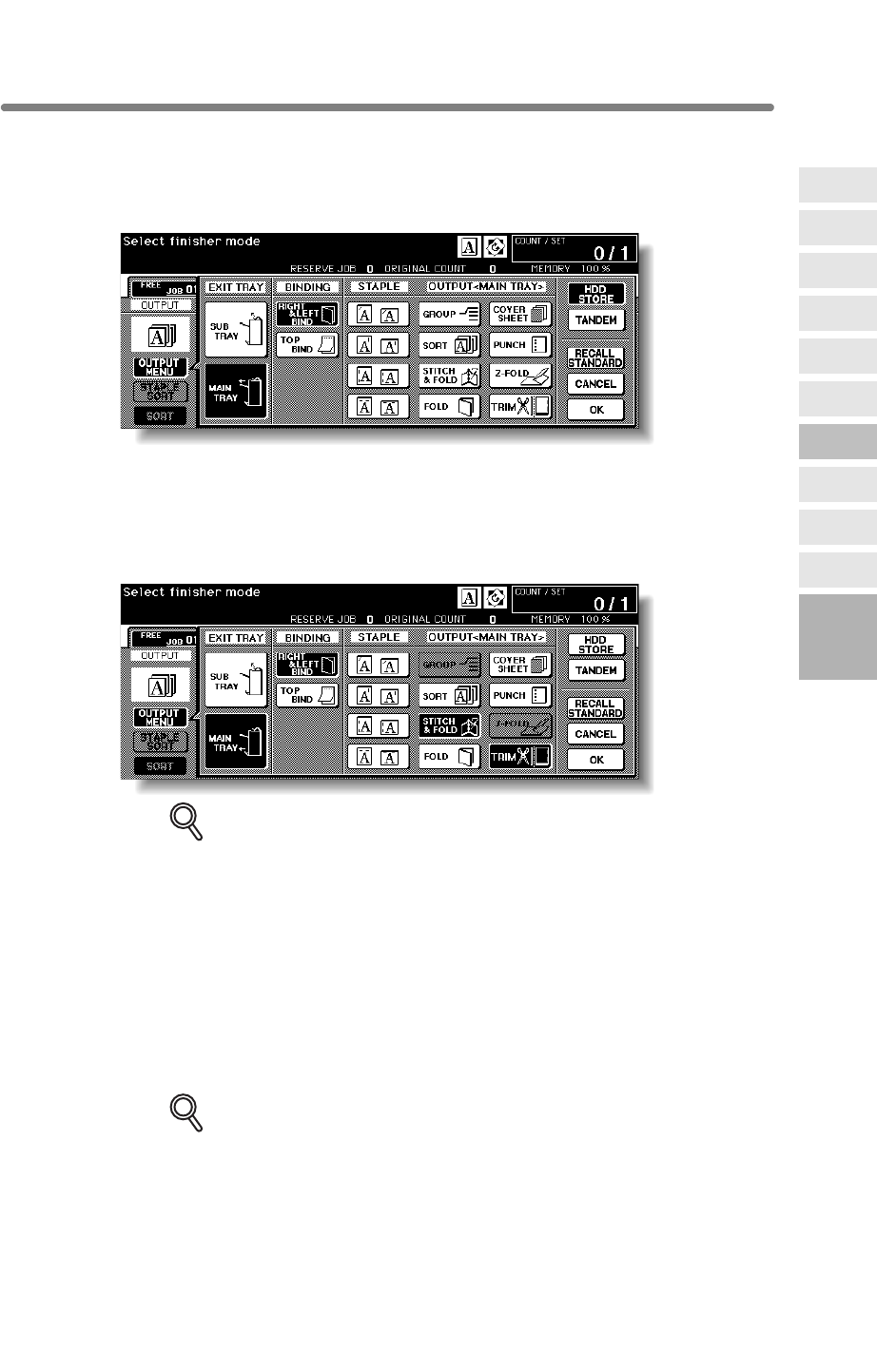
Making Trimmed Booklet (Trimming) (continued)
7-17
1. Touch OUTPUT MENU on the Basic Screen
The Output Mode popup menu will be displayed.
2. Touch MAIN TRAY, if not highlighted.
3. Select the desired trimming mode.
Touch STITCH & FOLD or FOLD, as desired.
When selecting FOLD, also touch TRIM to highlight it.
When selecting STITCH & FOLD, the machine with the trimmer unit installed selects
TRIM automatically.
DETAILS
• When copying two-sided signature originals using the Fold or Stitch &
Fold mode, release the automatically selected Booklet mode on the
Application Selection Screen.
• When copying dark originals or using Reverse Image mode together with
Fold or Stitch & Fold mode, the folded line of the output copies may be
slightly shifted.
4. Touch OK on the Output Mode popup menu.
The Basic Screen will be restored and the selection made in the output mode will be
reflected in the OUTPUT icon area.
5. Select additional copying features, as required.
DETAILS
NO COVER SHEET of Booklet is initially selected.
To change this selection, touch APPLICATION on the Basic Screen to
display the Application Selection Screen, then touch Booklet twice to
display the Booklet Mode Selection Screen to make another selection or to
release the setting.
7
Advanced
Information
Using Finisher
Manually
Cover Sheet
Feeding
Trimming
Z-Fold
Tandem Mode
Punch
Fold /
Stitch&Fold
Vertical/Hori-
zontal Zoom
Rotation
Weekly
Timer
Making Trimmed Booklet (Trimming) (continued)
7-18
6. Enter the desired print quantity from the control panel keypad.
HINT
See p. 3-7 for details on setting print quantity.
7. Position original(s).
HINT
See p. 3-2 to p. 3-6 for details on positioning originals.
DETAILS
When loading originals, heed the following limits on capacity:
Fold mode:
12 pages or less for simplex copying
6 pages or less for duplex copying
Stitch & Fold mode:
80 pages or less for simplex copying
40 pages or less for duplex copying
Exceeding the above capacity limits may cause trouble in the Finisher.
8. Press [START].
CAUTION
When the Trimmer unit tray capacity is exceeded, the Finisher
and Trimmer unit will cease operating. To avoid this, select the
appropriate print quantity from the specifications shown on p.
7-16.
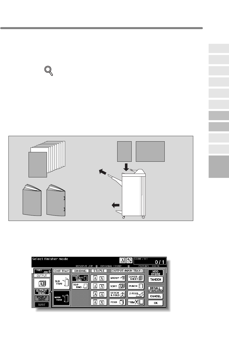
7-19
Cover Sheet Feeding
DETAILS
• Paper loaded into the cover sheet feeder cannot be copied.
• This function is incompatible with cover sheet mode (COVER WITH
COPY SHEET and COVER WITH BLANK SHEET) in Booklet and cover
mode in Sheet/Cover Insertion.
>>>Specifications for Cover Sheet Feeding<<<
❒Cover paper size: A3, B4, F4, A4, A4R, B5*, A5*
*B5 and A5 paper sizes are available in portrait type feeding only.
❒Tray capacity: 200 sheets (200 g/m2 paper) or 30mm thick
❒Incompatible Conditions:
Output to Secondary (sub) tray, Cover sheet mode in
Booklet, OHP Interleav
e
1. Touch OUTPUT MENU on the Basic Screen
The Output Mode popup menu will be displayed.
2. Touch MAIN TRAY, if not highlighted.
Cover sheet
Copied set with
cover attached
Copied sets with cover
attached in Fold or
Stitch & Fold mode
7
Advanced
Information
Using Finisher
Manually
Cover Sheet
Feeding
Trimming
Z-Fold
Tandem Mode
Punch
Fold /
Stitch&Fold
Vertical/Hori-
zontal Zoom
Rotation
Weekly
Timer
The Cover Sheet Feeder (Q3221A) is available as an option on the Q3219A/Q3220A
Finisher. Load cover sheet paper into this device and use the sheets as front covers
for copied sets output to the Main tray or use the sheets as booklet-type covers for
copied sets output to the Booklet tray or Trimmer unit tray in the Fold, Stitch & Fold,
or Trimming mode.
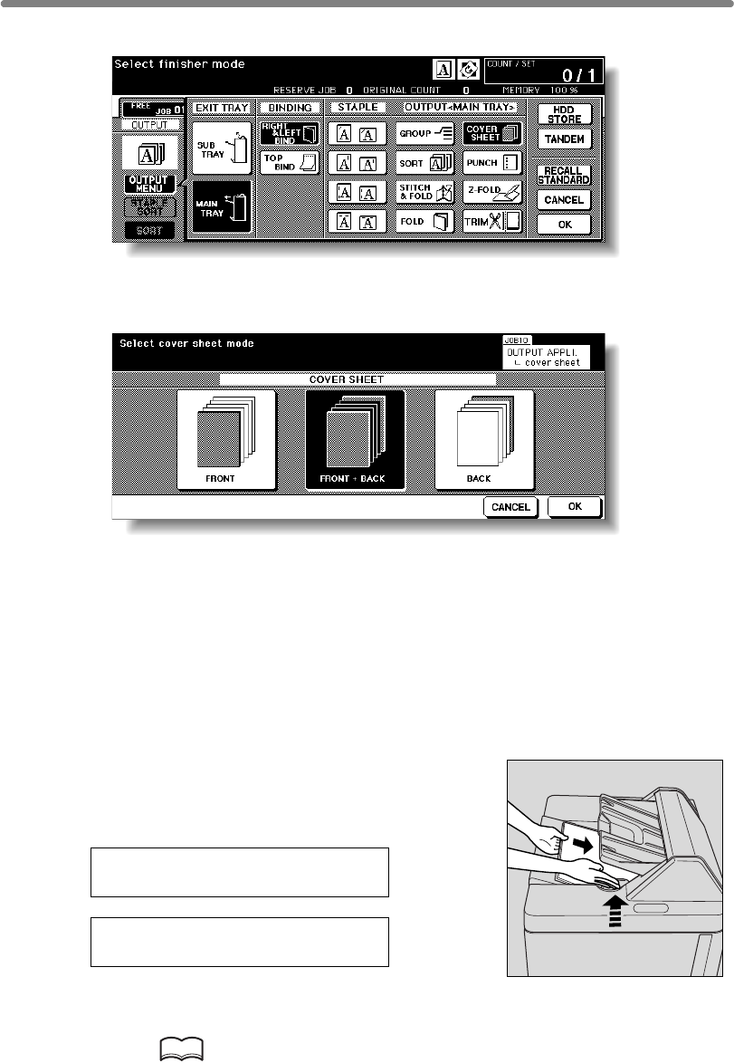
Cover Sheet Feeding (continued)
7-20
3. Touch COVER SHEET.
The Cover Sheet Mode Selection Screen will be displayed.
4. Touch FRONT, FRONT+BACK, or BACK to highlight it.
5. Touch OK to restore the Output Mode popup menu.
6. Touch OK on the Output Mode popup menu.
The Basic Screen will be restored.
7. Select additional copying features, as required.
8.
If the paper size loaded in the cover sheet feeder is not
suitable for the selected copy conditions, the following
messages will be displayed and copying will be
unavailable till the correct size is loaded.
Please load cover sheet in
cover sheet feeder
Adapt paper size between
cover sheet and selected paper
9. Enter the desired print quantity from the control panel keypad.
HINT
See p. 3-7 for details on setting print quantity.
Load the cover sheet paper into the optional cover sheet feeder of the
Q3219A/Q3220A Finisher.

Cover Sheet Feeding (continued)
7-21
10. Position originals.
HINT
See p. 3-2 to p. 3-6 for details on positioning originals.
11. Press [START].
CAUTION
When the finisher exit tray capacity is exceeded due to the print
quantity selected, remove the copied sets as they exit;
otherwise, mishandled paper will occur.
7
Advanced
Information
Using Finisher
Manually
Cover Sheet
Feeding
Trimming
Z-Fold
Tandem Mode
Punch
Fold /
Stitch&Fold
Vertical/Hori-
zontal Zoom
Rotation
Weekly
Timer

7-22
Using Finisher Manually
To use this convenient function, simply place a set of paper into the cover sheet feeder,
select the desired mode from the Manual Finishing operation panel located on the top
of the Finisher, then press the Start/Stop button.
Available finishing modes according to the optional configuration are described below.
• 1 oblique staple
• 2 parallel staples
• 1 oblique staple
• 2 parallel staples
• Stitch & Fold (2 staples in the centre + Fold)
• 1 oblique staple
• 2 parallel staples
• Stitch & Fold and Trimming (2 staples in the centre + Fold + Trimming)
>>>Specifications for Manual Staple 1 oblique staple and 2 parallel staples<<<
❒Paper size: A3, B4, F4, A4, A4R, B5, A5
❒Paper weight: 60 ~ 90 g/m2 paper
❒Staple capacity: 50 sheets max. (80 g/m2 paper)
❒Output tray: Primary (main) tray
>>>Specifications for Manual Stitch & Fold mode<<<
❒Paper size: A3, B4, A4R
❒Paper weight: 60 ~ 90 g/m2 paper
❒Staple capacity: 20 sheets max. (80 g/m2 paper)
19 sheets max. (80 g/m2 paper with a thick paper cover)
❒Output tray: Booklet tray
>>>Specifications for Manual Stitch & Fold and Trimming mode<<<
❒Paper size: A3, B4, A4R
❒Paper weight: 60 ~ 90 g/m2 paper
❒Staple capacity: 16 sheets max. (80 g/m2 paper)
15 sheets max. (80 g/m2 paper with a thick paper cover)
❒Output tray: Trimmer unit tray
This function is available only with the Cover Sheet Feeder option (Q·3221A) installed
onthe Q3219A/Q3220A Finisher.
Q3219A Finisher + Q3221A Cover Sheet Feeder
Q3220A Finisher + Q3221A Cover Sheet Feeder
Q3220A Finisher + Q3221A Cover Sheet Feeder + Q3224A Trimmer Unit
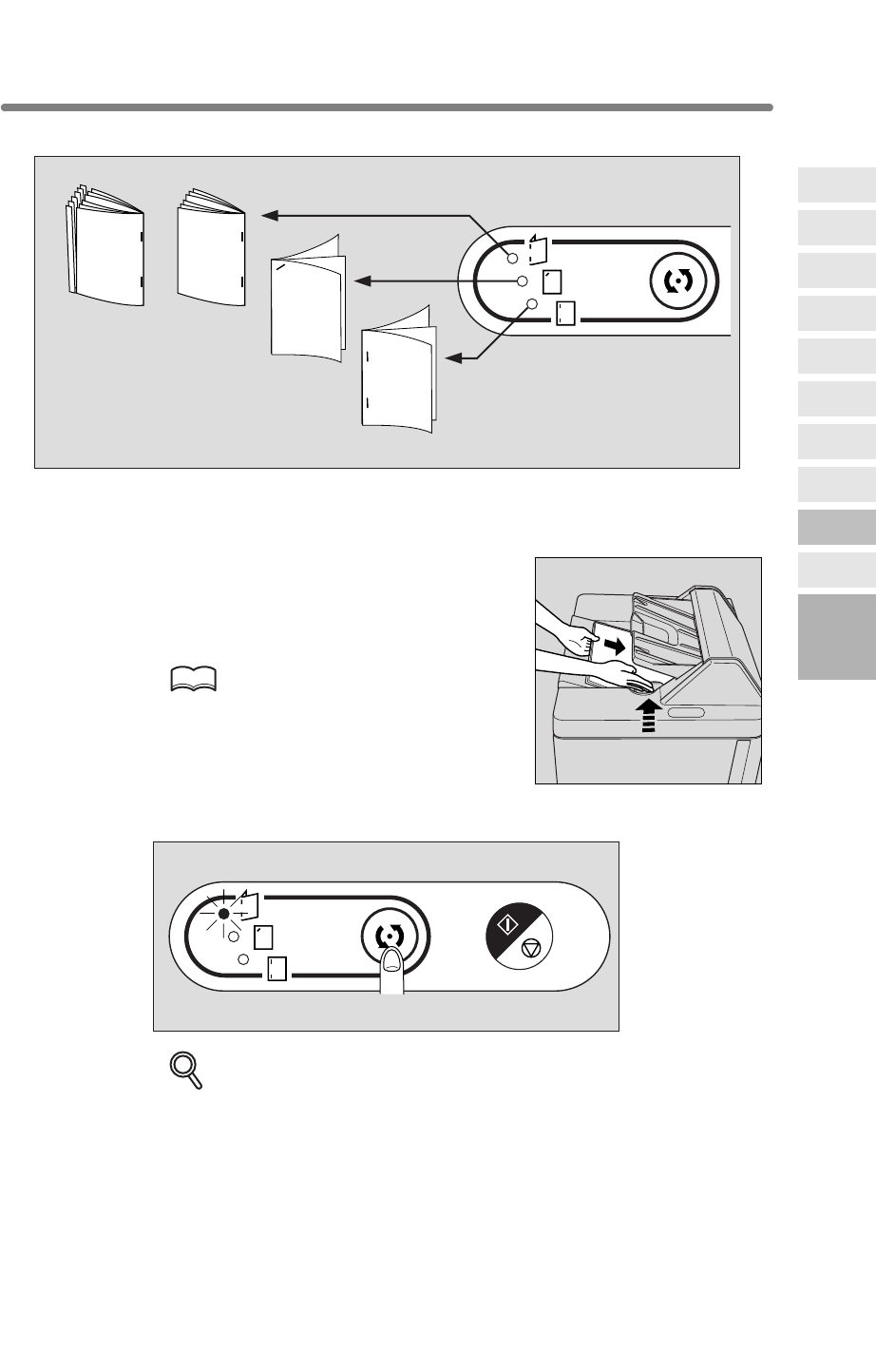
Using Finisher Manually (continued)
7-23
1. Place a set of paper to be finished into the cover sheet feeder, as
described below for each mode.
•1
oblique staple / 2 parallel staples: FACE UP
• Stitch & Fold (and Trimming):
FACE UP for the outside of the finished set
Align the guide plate. The indicator light of Start/Stop
button will turn green.
HINT
Refer to the specifications for available paper
size and capacity in each mode.
2. Press Staple Mode Selection button to select the desired mode.
DETAILS
MA
N
Stitich & Fold
Stitch & Fold
and Trimming
1 oblique staple
2 parallel staples
Manual finishing operation panel
MANUAL OPERATION
7
Advanced
Information
Using Finisher
Manually
Cover Sheet
Feeding
Trimming
Z-Fold
Tandem Mode
Punch
Fold /
Stitch&Fold
Vertical/Hori-
zontal Zoom
Rotation
Weekly
Timer
When selecting Stitch & Fold mode, the machine with the Q3224A Trimmer
unit installed will trim the end of booklet automatically.
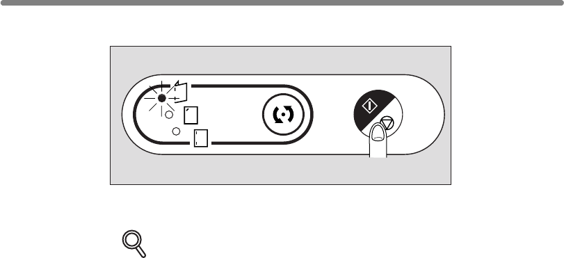
Using Finisher Manually (continued)
7-24
3. Press Start/Stop button.
Finished sheets will be delivered to the appropriate tray according to the selected
mode.
DETAILS
If you want to stop the Manual Finishing operation, press the Start/Stop
button again. The Finisher will cease operating. When using Stitch & Fold
mode, the unfinished set will be left in the stacker unit inside the Finisher.
MANUAL OPERATION

7-25
desired.
>>>Specifications for Tandem Mode<<<
cables.
Select the copying conditions, scan originals, and press [START] on the primary
❒Auto low power/Auto shut-off may function while tandem mode is selected.
mode, the power saving mode will be released automatically.
setting, the power saving mode will be released automatically when printing job
starts.
the tandem mode will be released automatically.
mode will be released automatically.
❒Auto reset may function while tandem mode is selected.
Initially, the tandem mode will be released automatically if Auto reset is activated on
deactivate the tandem mode.
output in tandem mode copying.
when using multiple trays for a single job.
❒Incompatible Conditions: Rotation Sort, Rotation Group, Group, Rotation, OHP
Interleave, SET NUMBERING and WATERMARK NUMBERING in Stamp
7
Advanced
Information
Using Finisher
Manually
Cover Sheet
Feeding
Trimming
Z-Fold
Tandem Mode
Punch
Fold /
Stitch&Fold
Vertical/Hori-
zontal Zoom
Rotation
Weekly
Timer
half the time of non-tandem mode.
(Q3637A/Q3638A).
Using Two mfps in Tandem
Tandem mode enables your hp 9085mfp primary (master) mfp to work in tandem
completion of large copying jobs. Two units working in tandem distribute a job in
Service setting is required to use the tandem mode. Contact your service representative, if
with the hp 9085mfp secondary (sub) mfp for the purpose of providing faster
❒The two mfps should be connected in either way described below.
(1) Connect the two mfps directly using a crossover cable. In this case, other
to connect the machines.
network functions provided to the mfp will be unavailable.
Use the straight-through or crossover cables of Category 5 or of the later standard
(2) Connect each of the two mfps to the hub in a network using straight-through
❒Two mfps should be turned on and ready for copying.
❒The mfp with the TANDEM key highlighted on the Output Mode popup menu will
❒Print quantity must be set for [2] or more copies to activate the tandem mode. When
the print quantity entered is an odd number, the primary mfp will copy and output
one sheet/set more than the secondary mfp to accommodate the job.
• The tandem mode will not be selected when the secondary mfp is turned off by
• If Auto low power is activated on the secondary mfp during the tandem job
• If Auto shut-off is activated on the secondary mfp during the tandem job setting,
• If Auto low power/Auto shut-off is activated on the primary mfp, the tandem
the primary mfp.
Key operator can set the primary mfp to select the tandem mode as initial setting.
Apply this setting to the primary mfp only, if desired. Setting on both mfps will
trouble occurs in either the primary or secondary mfp to allow the trouble-free
mfp to complete the job.
❒
The hp 9085mfp is provided with an Allocation recovery mode, which functions when
copying will be available by entering the ECM password in the primary mfp only.
The password will be transmitted to the secondary mfp.
❒ When the two mfps in tandem mode have the same ECM password registered,
❒Interrupt copying is available only on the mfp with [INTERRUPT] pressed.
❒If the primary mfp is installed with HDD, the image data stored in HDD can be
❒Corresponding tray sizes on the primary and secondary mfps should be the same
❒Two mfps should have the same optional configuration except for the option tray
be the primary (master) mfp, turning both mfps into the tandem mode.
mfp to operate both mfps in tandem to complete a job.
• If the tandem mode is selected while the secondary mfp is in Auto low power
Auto shut-off. Release the Auto shut-off mode by pressing [SLEEP ON/ OFF]
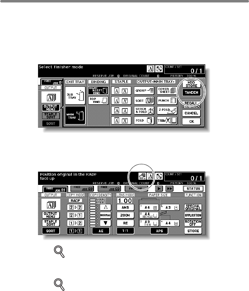
7-26
1.
2.
The Output Mode popup menu will be displayed.
3. Touch TANDEM to highlight it, then touch OK.
DETAILS
operation.
DETAILS
The tandem mode cannot be selected/continued in the cases shown below.
The message “Please wait/ Reserve is not available in Sub machine,” “Sub
machine error/ Please check sub machine,” or “Please check sub machine”
will be displayed, as required.
•
it.
• Selected tandem mode will be released automatically when the secondary
it, then select the tandem mode again to restart the procedure.
•
printing; however, the problem will not cause tandem mode to be released.
Take the appropriate troubleshooting measures to be ready for copying.
Using Two mfps in Tandem (continued)
Turn power on by pressing the Power switches of the two mfps.
Confirm that both mfps are ready to copy with the Basic Screen displayed.
The mfp with TANDEM highlighted will become the primary mfp; the other mfp
Touch OUTPUT MENU on the Basic Screen of either mfp.
will function as the secondarymfp. The Master icon displays on the Basic Screen of
the primary mfp to indicate that the two units are ready to work in tandem mode.
The Sub icon will display on the Basic Screen of the secondary mfp when
[START] is pressed on the primary mfp to start the tandem printing
When any problem occurs in the secondary mfp, such as a paper
The tandem mode cannot be selected while the secondary mfp is in the
misfeed or lack of paper, the secondary mfp will be unavailable for
off state, due to Auto shut-off. Press [
SLEEP ON/OFF
] to release
mfp activates Auto shut-off. Press [
SLEEP ON/OFF
] to release

7-27
• Tandem printing job cannot be started if 10 reserve jobs (not in tandem
•
4.
DETAILS
the tandem mode setting.
5.
will each copy and output 50 sheets.
DETAILS
•
mode.
•
accommodate the job.
6. Position original(s) FACE UP in the document feeder or FACE DOWN
HINT
See p. 3-2 to p. 3-6 for details on positioning originals.
7.
The Sub icon (
completed, and the Master and Sub icons on each Basic Screen will disappear.
DETAILS: Entering reserve job during Tandem mode copying
If scanning of the next reserved job is performed during the tandem mode
copying, that job will also be performed in the tandem mode. Up to 10 jobs
including the present job can be reserved.
until the interrupt copying is completed.
If the interrupt mode period is of long standing, the Allocation recovery
quantity.
7
Advanced
Information
Using Finisher
Manually
Cover Sheet
Feeding
Trimming
Z-Fold
Tandem Mode
Punch
Fold /
Stitch&Fold
Vertical/Hori-
zontal Zoom
Rotation
Weekly
Timer
Using Two mfps in Tandem (continued)
Selected tandem mode will be released automatically when the primary
then select the tandem mode again to restart the procedure.
are completed on the secondary mfp.
mode) are entered on the secondary mfp. Wait until the reserve jobs
mfp activates Auto low power/Auto shut-off.
Select the desired copying conditions on the primary mfp.
Ordinary copying operation is still available on the secondary mfp during
Enter print quantity on the primary mfp, using the keypad.
When a print quantity amount of 100 is entered, the primary and secondary mfps
When the print quantity entered is an odd number, the primary mfp will
Print quantity must be set for [3] or more copies to activate the tandem
copy and output one sheet/set more than the secondary mfp to
on the platen glass of the primary mfp.
) will display on the Basic Screen of the secondary mfp to
The tandem mode will be released automatically when tandem mode copying is
Press [START] on the control panel of the primary mfp.
indicate that the two mfps will start working in tandem.
Interrupt mode during Tandem mode copying
Interrupt copying is available only on the mfp with [
INTERRUPT
] pressed.
The tandem mode copying on the mfp in interrupt mode will be suspended
mode will activate to enable the other mfp to handle the remaining print
Press [SLEEP ON/OFF] to release Auto shut-off if required,
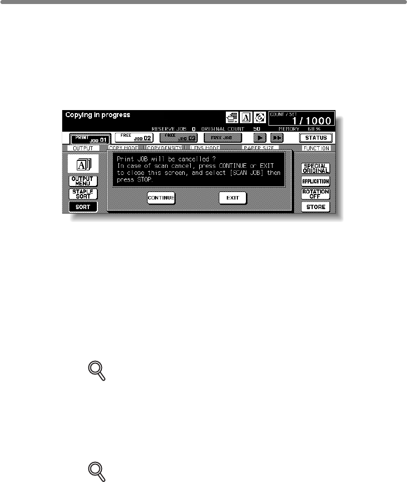
7-28
To Stop Scanning/Printing
To cancel the tandem copying job:
1.
The scanning/printing job stops immediately, and the popup menu appears on the
At this time, the tandem mode is not released.
2. Touch CONTINUE to go on, or EXIT to delete all the scanned data and
to release the tandem mode.
1.
or cease the operation. At this time, the tandem mode is not released.
the remaining print quantity.
2.
DETAILS
the popup menu.
Using Two mfps in Tandem (continued)
Press [STOP] on the control panel of the primary mfp.
Basic Screen of the primary mfp to ask you whether to continue or terminate the job.
Press [STOP] on the control panel of the secondary mfp.
appears on the Basic Screen of the secondary mfp to ask you whether to continue
DETAILS
The secondary mfp stops the current operation immediately, and the popup menu
To cancel the job in the secondary mfp only:
If temporary suspension in the secondary mfp takes a long time, the
Allocation recovery mode will activate, enabling the primary mfp to handle
the secondary mfp and to release the tandem mode.
The primary mfp will take over the remaining print quantity and complete the job.
Once the Allocation recovery mode is activated and the primary mfp is
continue with the tandem printing job, even when CONTINUE is touched on
Touch CONTINUE to go on, or EXIT to delete all the data transmitted to
already handling the remaining print quantity, the secondary mfp cannot

7-29
Troubleshooting
Copying with the Allocation recovery mode:
The Allocation recovery mode enables you to complete your copying job even when
DETAILS
Contact your service representative if you do not require this function.
When a paper jam, SC-code (E-code, F-code) trouble or unloaded paper occurs
job.
When the job is completed, take the appropriate troubleshooting measures to correct
the problem.
The scanning job will stop immediately, and the tandem copying job will be suspended
available after completing some reserve jobs. In this case, the Allocation recovery
The tandem mode will be released automatically in either case. Restart the procedure
from the first step.
7
Advanced
Information
Using Finisher
Manually
Cover Sheet
Feeding
Trimming
Z-Fold
Tandem Mode
Punch
Fold /
Stitch&Fold
Vertical/Hori-
zontal Zoom
Rotation
Weekly
Timer
In that case, the mfp that is trouble free completes the job.
The mfp is initially set to activate this function.
on either the primary or secondary mfp:
The mfp that is trouble free handles the remaining print quantity and completes the
Using Two mfps in Tandem (continued)
trouble occurs in either the primary or secondary mfp, such as a paper jam.
On the primary mfp
on both mfps. At this time, the tandem mode is not released.
Take the same measure to be applied for single mfp referring to p. 5-11 ~ p. 5-12.
On the secondary mfp
The secondary mfp will start the tandem copying job when the memory becomes
secondary mfp becomes available for the job.
If the memory of the secondary mfp does not become available despite the elapse of
time, the tandem mode will be released on the secondary mfp, and the Allocation
mode functions to continue the tandem printing job on the primary mfp until the
recovery mode functions to complete the job on the primary mfp.
When memory overflow occurs on either the primary or secondary mfp:
When the power is turned off on either the primary or secondary mfp:
7-30
blank page

8
8
Special
Original
Original
Form
SDF
Z-Folded
Original
Mixed
Original
Text/Photo
Enhance
Original
Direction
Special Original
How to Make a Copy of Special Original
Copying Mixed Size Originals (Mixed Original) ...................................... 8-6
Copying Z-Folded Originals (Z-Folded Original).................................... 8-8
Copying Non-Standard Size Originals (Original Form)......................... 8-12
Specifying Original Direction .............................................................. 8-2
Making Copy Quality Closer to Originals (Text/Photo Enhance) ............ 8-4
Feeding Single Original from RADF (SDF)........................................... 8-10
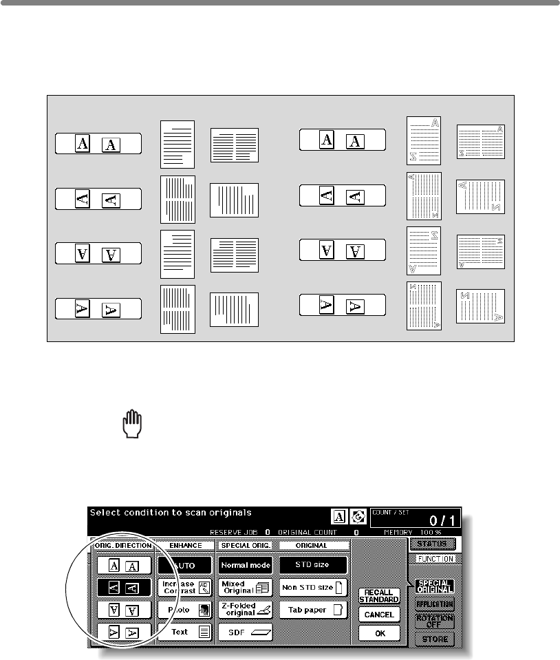
8-2
Specifying Original Direction
This setting is required to obtain copy results as expected when making double-sided
copies with binding position specified or when staple position is specified.
1. Touch SPECIAL ORIGINAL on the Basic Screen.
The Special Original popup menu will be displayed.
Reminder!
press [AUTO RESET].
2. Touch to highlight the desired original direction key.
A
Z
A
Z
A
Z
A
Z
A
Z
A
Z
A
Z
A
Z
Originals on platen glass:
Specify the direction of the originals placed on RADF or platen glass.
Originals on RADF:
When starting a new copying job, be sure to close the RADF securely, then
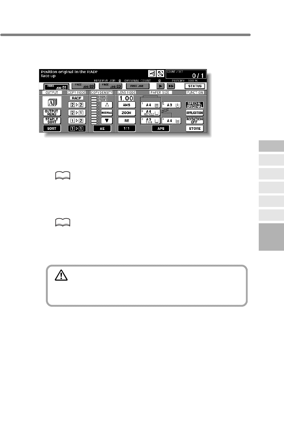
Specifying Original Direction (continued)
8-3
3. Touch OK to complete the setting and return to the Basic Screen.
The SPECIAL ORIGINAL key on the Basic Screen is highlighted, and the icon in the
message area indicates the selected original direction.
4. Make other compatible selections.
5. Enter the desired print quantity from the control panel keypad.
HINT
See p. 3-7 for details on setting print quantity.
6. Position originals FACE UP in the document feeder or FACE DOWN
on the platen glass according to the original direction specified in
step 2.
HINT
See the illustration on previous page, and p. 3-2 to p. 3-6 for details on
positioning originals.
7. Press [START].
CAUTION
When the finisher / trimmer unit / paper exit tray capacity is
exceeded due to the print quantity selected, remove the copied
sets as they exit; otherwise, mishandled paper will occur.
8
Special
Original
Original
Form
SDF
Z-Folded
Original
Mixed
Original
Text/Photo
Enhance
Original
Direction
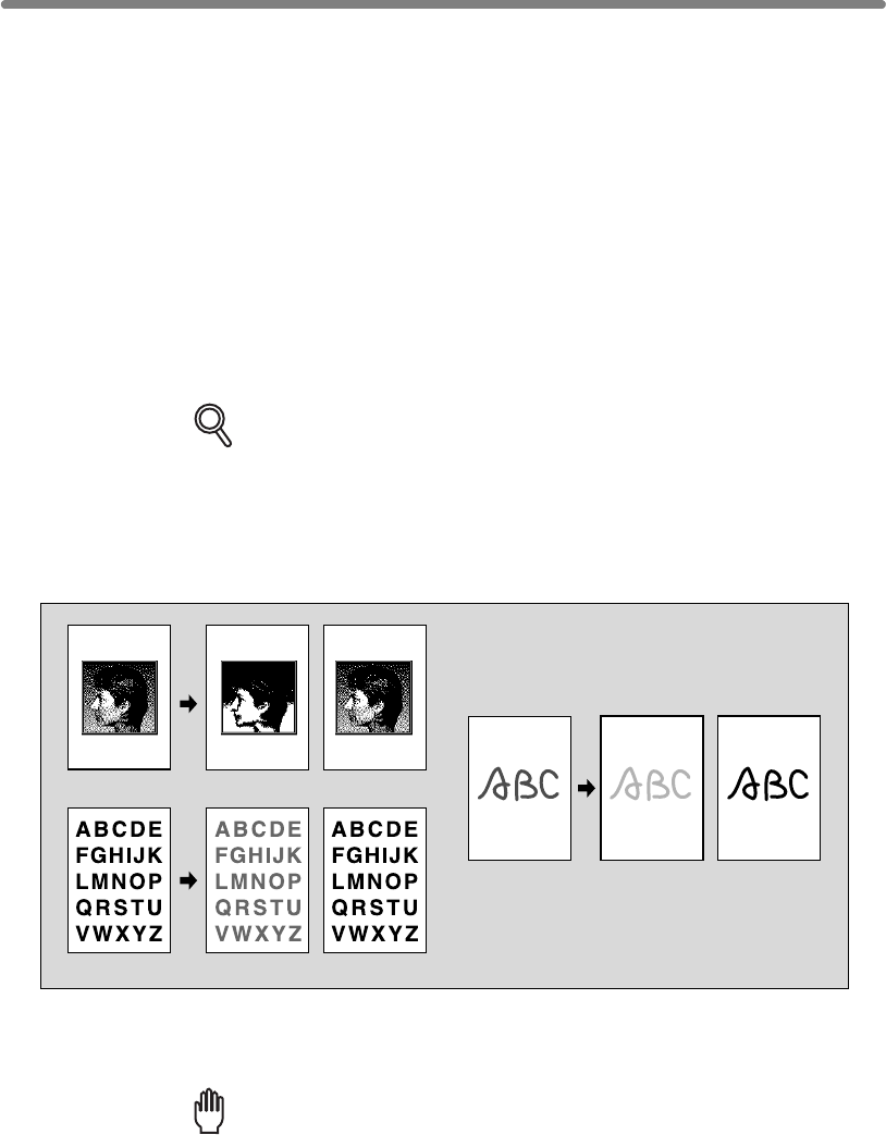
8-4
Making Copy Quality Closer to Originals (Text/Photo Enhance)
Use this function to enhance the reproducibility of half tones so that the copy quality
more closely matches to that of the original.
Text Mode
Use the Text mode when copying a text original. In this mode, text is improved in
comparison to using the general mode.
Photo Mode
Use the Photo mode to reproduce a half-tone photo image. The copy will closely
represent the half-tones of the original image.
Increase Contrast Mode
Select Increase Contrast to darken lightly printed images (e.g., pencil) without changing
background exposure. In cases where the image is light and background is dark, the
background will not be changed.
DETAILS
In each enhance mode, the copy density level can be shifted three levels
darker or three levels lighter (Density Shift).
See p. 3-20 if this setting is desired.
>>>Specifications for Text/Photo Enhance<<<
❒Incompatible Copying Conditions: None
1. Touch SPECIAL ORIGINAL on the Basic Screen.
The Special Original popup menu will be displayed.
Reminder!
press [AUTO RESET].
Original Photo modeAuto mode
Original Text modeAuto mode
Original Increase contrast
mode
Auto mode
When starting a new copying job, be sure to close the RADF securely, then
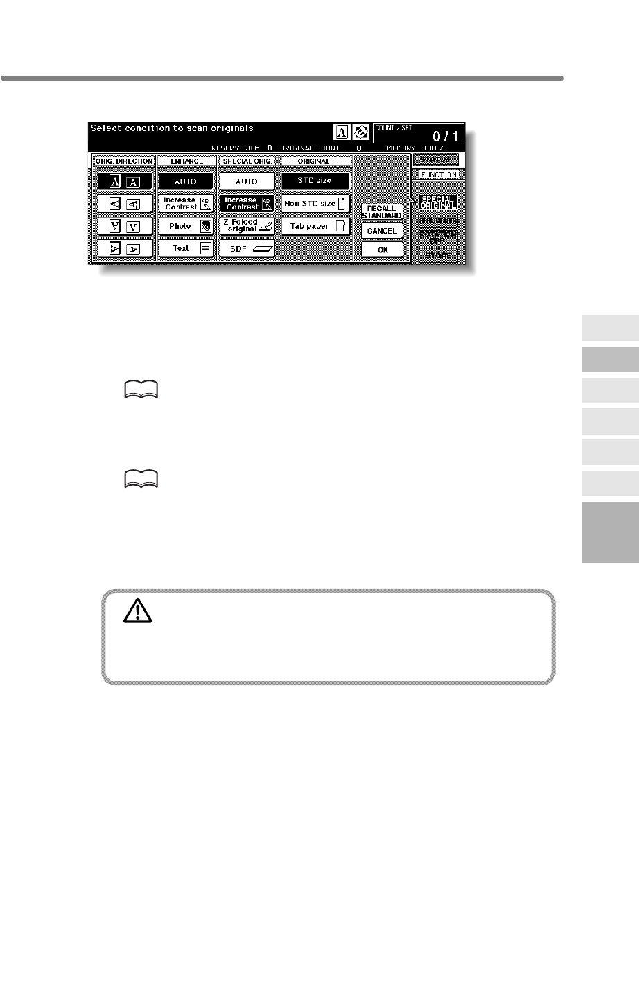
Making Copy Quality Closer to Originals (Text/Photo Enhance) (continued)
8-5
2. Touch Text, Photo, or Increase Contrast, as required.
3. Touch OK to return to the Basic Screen.
4. Select additional copying features, as desired.
5. Enter the desired print quantity from the control panel keypad.
HINT
See p. 3-7 for details on setting print quantity.
6. Position original(s) FACE UP in the document feeder or FACE DOWN
on the platen glass.
HINTS
• See p. 3-2 to p. 3-6 for details on positioning originals.
exceeds 100.
7. Press [START].
CAUTION
When the finisher / trimmer unit / paper exit tray capacity is
exceeded due to the print quantity selected, remove the copied
sets as they exit; otherwise, mishandled paper will occur.
8
Special
Original
Original
Form
SDF
Z-Folded
Original
Mixed
Original
Text/Photo
Enhance
Original
Direction
• Use RADF store mode (p. 3-32 to p. 3-33) when the original count
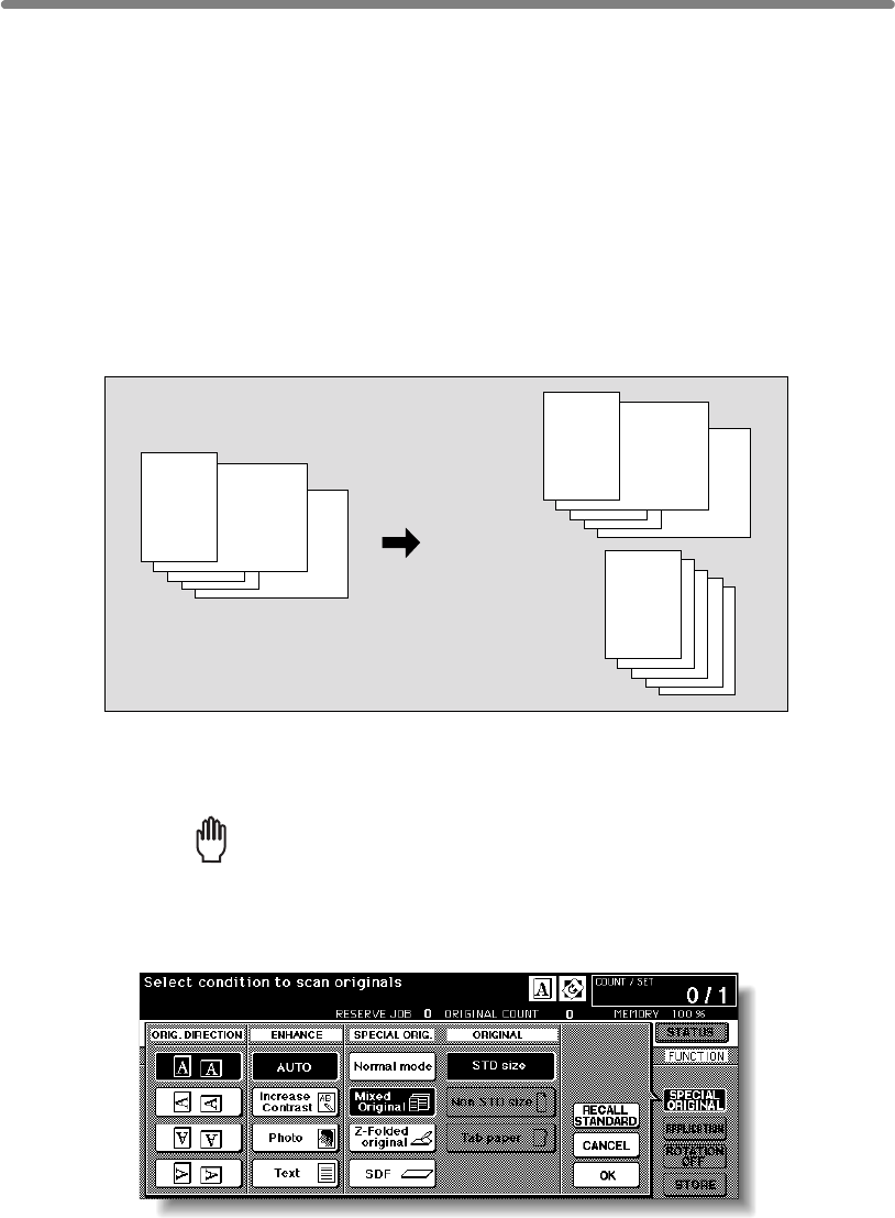
8-6
Copying Mixed Size Originals (Mixed Original)
Use the Mixed original mode with the document feeder or with Store mode to copy
mixed size originals.
Each original in the mixed set will be copied to paper of the same size (APS mode) or
to paper of desired size with appropriate ratio automatically selected (AMS mode).
>>>Specifications for Mixed Original<<<
❒Incompatible Conditions: Staple-Sort with APS, Rotation Sort, Fold, Stitch & Fold,
Trimming, Punch (A4R, B5R, A5, A5R mixed), Z-Folded Original, Non STD Size,
Tab Paper, Sheet/Cover Insertion, Chapter, Combination, Booklet, OHP Interleave,
Image Insert, Dual Page, Program Job, Non-Image Area Erase, Repeat, AUTO
Layout, Overlay, Storing image in Overlay Memory
1. Touch SPECIAL ORIGINAL on the Basic Screen.
The Special Original popup menu will be displayed.
Reminder!
press [AUTO RESET].
2. Touch Mixed Original.
3. Touch OK to return to the Basic Screen.
Mixed size originals
APS mode
Automatically
select the paper
of the same size
as that of the
original.
AMS mode
Automatically select
magnification ratio
to copy onto the
same paper in size.
nal guides. See p. 11-9 to p. 11-10 for details.
❒Use RADF.
❒Combination of original sizes to be mixed depends on the width of the RADF origi-
When starting a new copying job, be sure to close the RADF securely, then
Copying Mixed Size Originals (Mixed Original) (continued)
8-7
4. Select additional copying features, as desired.
DETAILS
APS is automatically selected on the Basic Screen.
To select AMS, touch the tray key on the Basic Screen to select the desired
paper size.
5. Enter the desired print quantity from the control panel keypad.
HINT
See p. 3-7 for details on setting print quantity.
6. Position mixed original(s) FACE UP in the document feeder.
HINTS
• See p. 3-3 for details on positioning originals.
•
7. Press [START].
CAUTION
When the finisher / paper exit tray capacity is exceeded due to
the print quantity selected, remove the copied sets as they exit;
otherwise, mishandled paper will occur.
8
Special
Original
Original
Form
SDF
Z-Folded
Original
Mixed
Original
Text/Photo
Enhance
Original
Direction
exceeds 100.
Use RADF store mode (p. 3-32 to p. 3-33) when the original count

8-8
Copying Z-Folded Originals (Z-Folded Original)
This mode requires more scanning time to detect the original size.
>>>Specifications for Z-Folded Original<<<
Original, Non STD Size, Tab Paper, Non-Image Area Erase, Repeat, AUTO Layout,
Storing image in Overlay Memory
1. Touch SPECIAL ORIGINAL on the Basic Screen.
The Special Original popup menu will be displayed.
Reminder!
press [AUTO RESET].
2. Touch Z-Folded original.
3. Touch OK to return to the Basic Screen.
4. Select additional copying features, as desired.
5. Enter the desired print quantity from the control panel keypad.
HINT
See p. 3-7 for details on setting print quantity.
Z-folded original
Use the Z-folded original mode with the document feeder to copy Z-folded originals.
❒Incompatible Conditions: Using platen glass, Fold, Stitch & Fold, Trimming, Mixed
Otherwise, the size detection sensor of the RADF may function incorrectly.
❒Use RADF.
When starting a new copying job, be sure to close the RADF securely, then

Copying Z-Folded Originals (Z-Folded Original) (continued)
8-9
6. Position mixed original(s) FACE UP in the document feeder.
HINTS
•
•
7. Press [START].
CAUTION
When the finisher / paper exit tray capacity is exceeded due to
the print quantity selected, remove the copied sets as they exit;
otherwise, mishandled paper will occur.
8
Special
Original
Original
Form
SDF
Z-Folded
Original
Mixed
Original
Text/Photo
Enhance
Original
Direction
exceeds 100.
See p. 3-4 for details on positioning originals.
Use RADF store mode (p. 3-32 to p. 3-33) when the original count
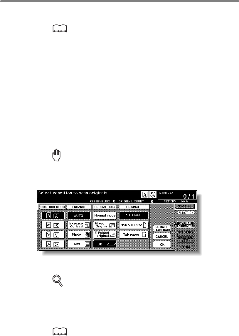
8-10
Use the SDF mode to copy thick originals or paste-ups to be fed one sheet at a time in
the document feeder.
HINT
Key operator can set the machine to automatically feed the original one
second after placing the original in the document feeder (Auto Start), when
>>>Specifications for SDF<<<
❒With the SDF mode selected, original paper specification will be different in simplex
and duplex copying modes.
Simplex original paper weight:50 ~ 200 g/m2
Duplex original paper weight: 50 ~ 130 g/m2
❒Incompatible Conditions: Using platen glass, Fold, Staple-sort, Group, Rotation sort,
Rotation group, Mixed Original, Z-Folded Original, FULL AREA in Non STD Size,
Sheet/Cover Insertion, Chapter, Combination, Booklet, Image Insert, Non-Image Area
Erase, Repeat except 2/4/8 Repeat, AUTO Layout, Overlay, Storing image in Overlay
Memory
1. Touch SPECIAL ORIGINAL on the Basic Screen.
The Special Original popup menu will be displayed.
Reminder!
press [AUTO RESET].
2. Touch SDF.
3. Touch OK to return to the Basic Screen.
DETAILS
If the Auto Start mode is specified in the Key operator setting, the STORE
key is highlighted on the Basic Screen when restored.
4. Select additional copying features, as desired.
5. Enter the desired print quantity from the control panel keypad.
HINT
See p. 3-7 for details on setting print quantity.
13-44 for Key operator functions.
Feeding Single Original from RADF (SDF)
the SDF mode is used together with RADF store mode. See p. 13-39 to p.
❒Use RADF. Set 1 sheet at a time.
When starting a new copying job, be sure to close the RADF securely, then
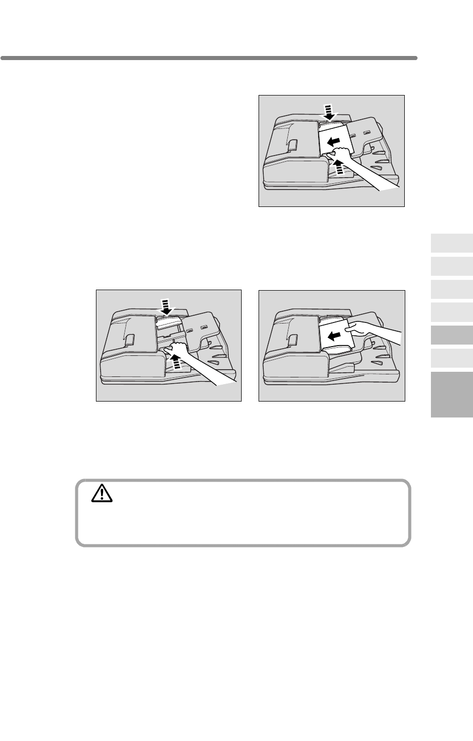
8-11
6. Position SDF original FACE UP in the document feeder.
In Normal SDF mode:
Position a sheet of the original in the document
feeder.
Never set more than one thick original or paste
up, otherwise machine trouble may be caused.
Adjust the paper guides according to the original size to be set, then position a sheet
of original in the document feeder.
The set original will be automatically fed and scanned.
Never set more than one original, otherwise machine trouble may be caused.
7. Press [START].
In normal SDF mode, the original will be fed and scanned, then the printing job will
start in succession when the machine becomes ready for output.
CAUTION
When the finisher / trimmer unit / paper exit tray capacity is
exceeded due to the print quantity selected, remove the copied
sets as they exit; otherwise, mishandled paper will occur.
8
Special
Original
Original
Form
SDF
Z-Folded
Original
Mixed
Original
Text/Photo
Enhance
Original
Direction
Feeding Single Original from RADF (SDF) (continued)
Auto Start mode with RADF store mode:
When scanning is completed, touch STORE to exit the RADF store mode.
In Auto Start mode with RADF store mode, the printing job will start immediately.
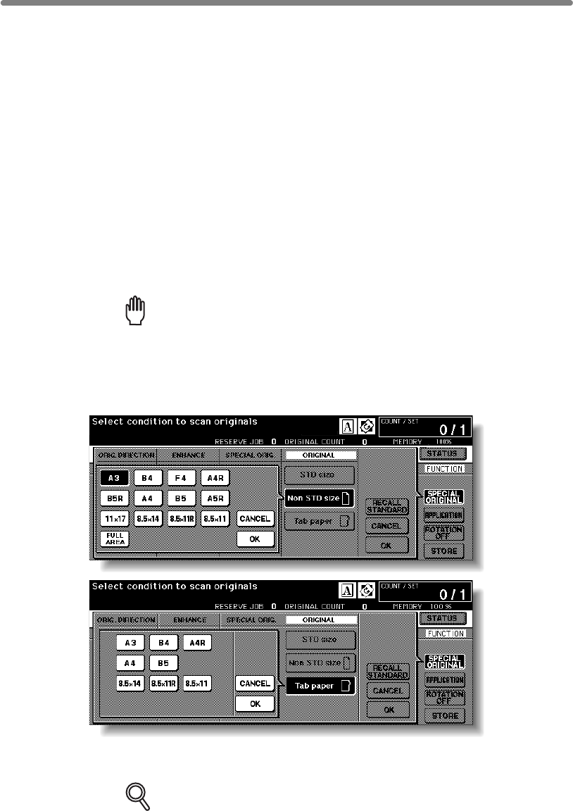
8-12
Copying Non-Standard Size Originals (Original Form)
Use Non STD size mode to specify the scanning area manually for copying or printing
special size originals. Use Tab paper mode to copy a tabbed original, including the
image of the tab part, onto tabbed copy paper.
>>>Specifications for Original Form<<<
❒Tab extension width: 12.5 mm or less
❒Incompatible with Non STD Size: Mixed Original, Z-Folded Original, Tab Paper,
Storing image in Overlay Memory
❒Incompatible with FULL AREA: Combination, Booklet, Dual Page, Non-Image Area
Erase, Image Shift
❒Incompatible with Tab Paper: Mixed Original, Z-Folded Original, Non STD Size,
Sheet/Cover Insertion, Chapter, Combination, Booklet, OHP Interleave, Image
Insert, Dual Page, Storing image in Overlay Memory
1. Touch SPECIAL ORIGINAL on the Basic Screen.
The Special Original popup menu will be displayed.
Reminder!
press [AUTO RESET].
2. Touch Non STD Size or Tab paper.
The popup menu will appear for Non STD size or Tab paper size setting.
3. Touch the desired size key.
DETAILS
scans the whole area of the platen glass and copies with the paper size or
magnification ratio currently selected.
positioned on the platen glass (STD size mode).
When starting a new copying job, be sure to close the RADF securely, then
The mfp usually detects the standard size of originals fed through RADF or
When selecting FULL AREA on the Non STD size mode menu, the mfp
Copying Non-Standard Size Originals (Original Form) (continued)
8-13
4. Touch OK on the popup menu to complete the setting.
The popup menu will disappear.
5. Touch OK to complete the setting and return to the Basic Screen.
6. Load copy paper.
HINTS
• To load tabbed copy paper in the Multi-sheet bypass tray, specify the
paper type as Tab paper. See p. 3-29 to p. 3-31.
To load tabbed copy paper in any other tray, specify the paper type as
Tab paper in the Key Operator mode. See p. 13-23 to p. 13-24.
• For the procedure of tabbed copy paper supply, see p. 2-28 to p. 2-30.
7. Enter the desired print quantity from the control panel keypad.
HINT
See p. 3-7 for details on setting print quantity.
8. Position original(s) FACE UP in the document feeder, or FACE DOWN
on the platen glass.
HINTS
• See p. 3-2 to p. 3-6 for details on positioning originals.
•
exceeds 100.
9. Press [START].
CAUTION
When the finisher / trimmer unit / paper exit tray capacity is
exceeded due to the print quantity selected, remove the copied
sets as they exit; otherwise, mishandled paper will occur.
8
Special
Original
Original
Form
SDF
Z-Folded
Original
Mixed
Original
Text/Photo
Enhance
Original
Direction
Use RADF store mode (p. 3-32 to p. 3-33) when the original count
8-14
blank page

9
9
Applications
Reverse
Image
Non-Image
Area Erase
Program Job
Dual Page
Image Insert
OHP
Interleave
Booklet
Combination
Chapter
Sheet/Cover
Insertion
Application
Selection Screen
Repeat
Frame/Fold
Erasure
AUTO
Layout
Full-Image
Area
Image Shift
Reduce &
Shift
Stamp
Overlay
Overlay
Memory
Applications
How to Use Application Functions
To Display Application Selection Screen................................................. 9-2
Inserting Sheets and Covers (Sheet/Cover Insertion) ........................ 9-3
Locating Title Pages on the Right Side (Chapter)................................... 9-7
Lay Out Several Pages onto One Sheet (Combination)................... 9-10
Making a Multiple Page Signature Booklet (Booklet)............................ 9-13
Copying onto Transparent Films (OHP Interleave)........................... 9-16
Inserting Images into Printed Sets (Image Insert)................................. 9-18
Dividing an Image into Right and Left Pages (Dual Page) ............... 9-21
P
rogramming Different Settings for an Output Job (Program Job)
.......... 9-25
Erasing Outside of the Original (Non-Image Area Erase) ................ 9-27
Reversing Colour in Black and White Image (Reverse Image) ............ 9-29
Repeating Selected Image Area (Repeat: Vert./Horiz. Mode).......... 9-31
Repeating Automatically or Selecting Repeating Times
(Repeat: AUTO/ Repeat Mode) ........ 9-34
E
liminating Black Copy Marks Along Borders (Frame/Fold Erasure)
.. 9-37
Copying Image in the Centre of Copy Paper (AUTO Layout)............... 9-40
Printing Images Fully to the Edges (Full-Image Area)...................... 9-42
Adjusting Position of Copy Image (Image Shift) ................................... 9-44
R
educing Images to Create Binding Margin (Reduce & Shift)
............. 9-47
Printing Stamp, Page, Date/Time onto Copies (Stamp) ....................... 9-50
Printing Watermark onto Copies (Stamp) ......................................... 9-56
O
verlaying an Image onto Each Page Copied in the Job (Overlay)
............ 9-59
S
toring an Overlay Image in HDD / Overlaying Image
Stored in HDD
(Overlay Memory)...... 9-61
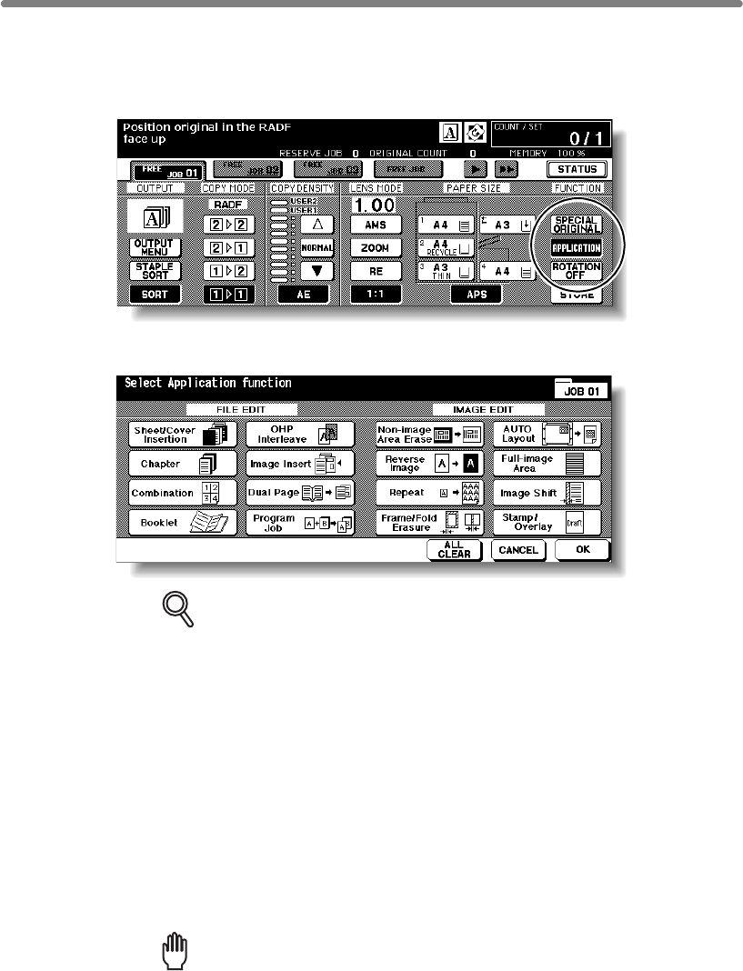
9-2
To Display Application Selection Screen
Follow the procedure below to display the Application Selection Screen and select the
desired copying features.
1. Touch APPLICATION on the Basic Screen.
The Application Selection Screen will be displayed on the touch panel.
DETAILS
• When a function key is touched, it becomes highlighted. If you touch a
function key, another screen or two will display to enable you to enter the
appropriate settings.
• Check BOOK MARK in the message area of the subsequent screen, if
desired, so that the screen may be directly accessed from the Check
Screen to change the setting you made.
• If one function on the menu is incompatible with another, it will appear
dimmed.
• The APPLICATION key on the Basic Screen will be highlighted when
application selections have been made.
To restore the original copying conditions, touch CANCEL.
To clear all Application settings, touch ALL CLEAR.
2. Touch OK on the Application Selection Screen.
Selections will be completed and the Basic Screen will be restored.
Reminder!
With the Basic Screen displayed, you can press [START] to perform the
operation.
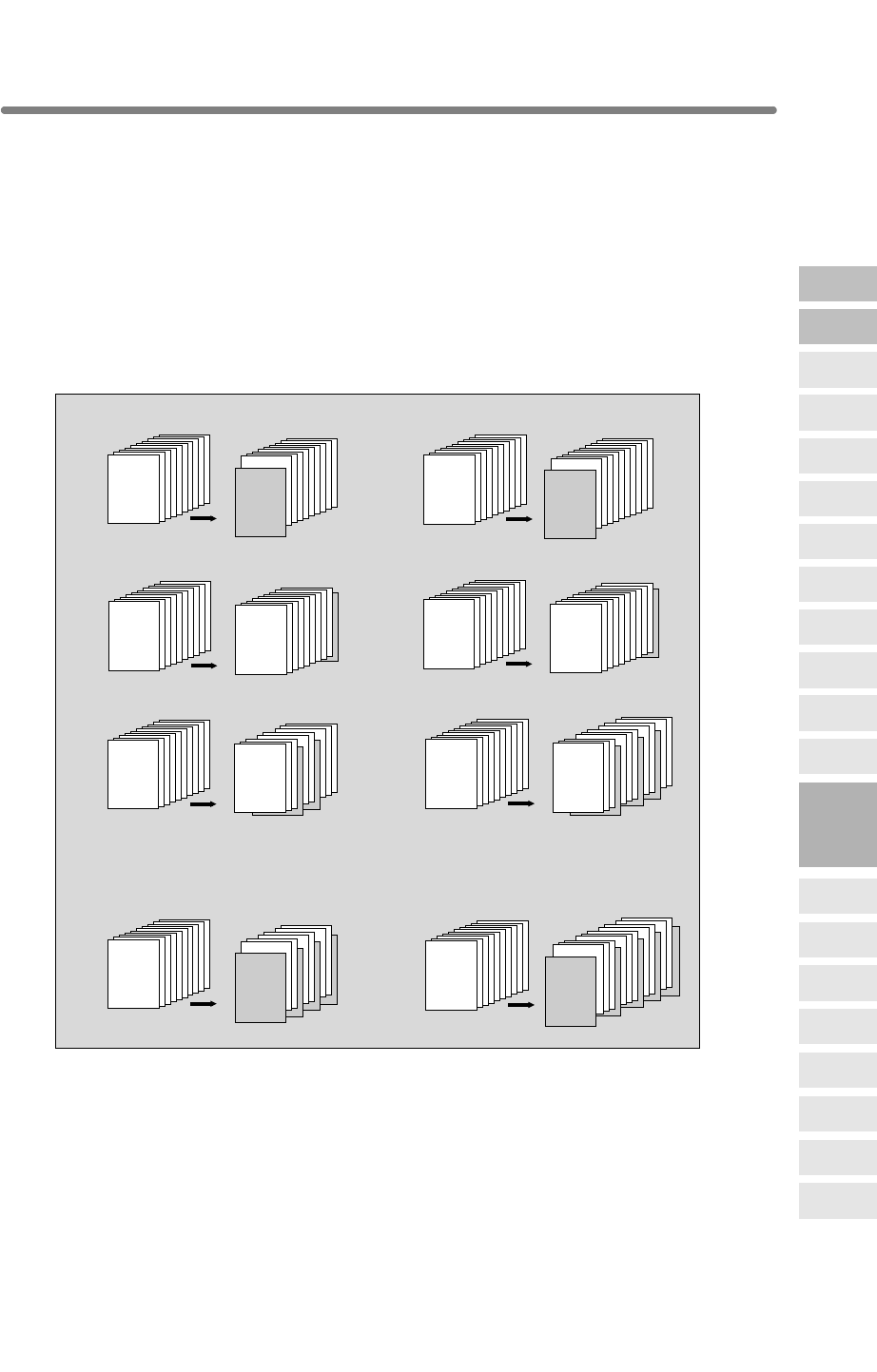
9-3
Inserting Sheets and Covers (Sheet/Cover Insertion)
Use Sheet/Cover Insertion in copy mode or blank mode to insert chapter sheets or
separator sheets into the finished set, as well as front and back covers.
>>>Specifications for Sheet/Cover Insertion<<<
❒
Trays for copy paper, front/back covers, and insertions should have the same paper
size loaded. AMS (Automatic Magnification Selection) is automatically selected.
❒Max. insert sheets: 30 locations, from 1~999, including front and back covers
❒
Incompatible Conditions: APS, Group, Rotation Sort, Rotaion Group, Fold/ Stitch&Fold/
Trimming (with Booklet selected), Mixed Original, Tab Paper, Combination, Booklet, OHP
Interleave, Image Insert, Dual Page, Program Job, Non-image Area Erase, Repeat
(except 2/4/8 Repeat), AUTO Layout, Overlay, Storing Image in Overlay Memory
123456789
10
123456789
10
SURVEYOR’S
REPORT
SURVEYOR’S
REPORT
123456789
10
123456789
10
SURVEYOR’S
REPORT
SURVEYOR’S
REPORT
123456789
10
123
4
56
7
89
10
SURVEYOR’S
REPORT
SURVEYOR’S
REPORT
123456789
10
1
23456789
10
SURVEYOR’S
REPORT
SURVEYOR’S
REPORT
123456789
10
1
23
4
56
7
89
10
SURVEYOR’S
REPORT
SURVEYOR’S
REPORT
123456789
10
123456789
10
SURVEYOR’S
REPORT
SURVEYOR’S
REPORT
123456789
10
123456789
10
SURVEYOR’S
REPORT
SURVEYOR’S
REPORT
123456789
10
123456789
10
SURVEYOR’S
REPORT
SURVEYOR’S
REPORT
Originals Copies
Originals Copies
Originals Copies
Originals Copies
Originals Copies
Originals Copies
FRONT COVER BLANK
BACK COVER BLANK
COPY SHEET INSERTION BLANK SHEET INSERTION
BACK COVER COPIED
Combination samples:
FRONT & BACK COVERS COPIED,
AND COPY SHEET INSERTION
FRONT & BACK COVERS BLANK,
AND BLANK SHEET INSERTION
FRONT COVER COPIED
9
Applications
Reverse
Image
Non-Image
Area Erase
Program Job
Dual Page
Image Insert
OHP
Interleave
Booklet
Combination
Chapter
Sheet/Cover
Insertion
Application
Selection Screen
Repeat
Frame/Fold
Erasure
AUTO
Layout
Full-Image
Area
Image Shift
Reduce &
Shift
Stamp
Overlay
Overlay
Memory
❒Use RADF.
❒The HCI cannot be selected as tray source if specified as Thick 3.
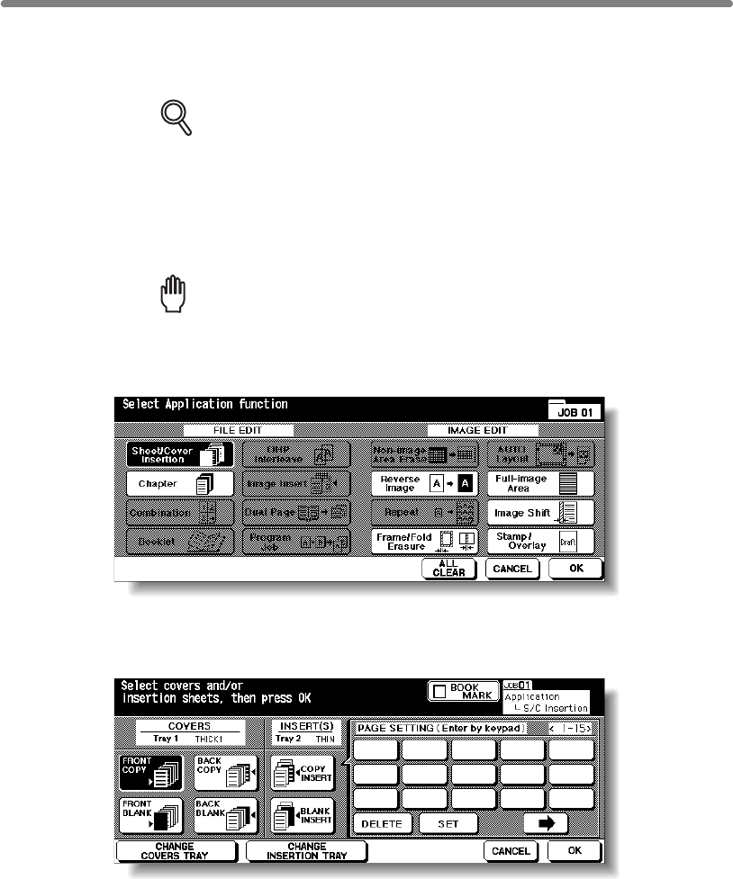
Inserting Sheets and Covers (Sheet/Cover Insertion) (continued)
9-4
1. Load regular sheets into any tray, and insertion sheets and covers
into each tray source to be designated on the Sheet/Cover Insertion
Screen.
DETAILS
• When using thick paper or tabbed paper for covers or insertions, load
them in the Multi-sheet bypass tray, unless previously specified and
loaded in any other tray.
• Be sure that the trays for copy paper, front/back covers, and insertions
have the same paper size loaded.
2. Touch APPLICATION on the Basic Screen.
Reminder!
press [AUTO RESET].
3. Touch Sheet/Cover Insertion on the Application Selection Screen.
The Sheet/Cover Insertion Screen will be displayed.
4. Select the desired cover mode.
Example: Touch FRONT COPY to insert a copied front cover.
5. Touch CHANGE COVERS TRAY to select the cover sheet tray source.
The tray source for covers currently selected is displayed on the Sheet/Cover Insertion
Screen.
Every touch of the key shifts the selection in the display that includes paper type as
specified in Key Operator mode.
If no insertion is desired, proceed to step 8.
When starting a new copying job, be sure to close the RADF securely, then
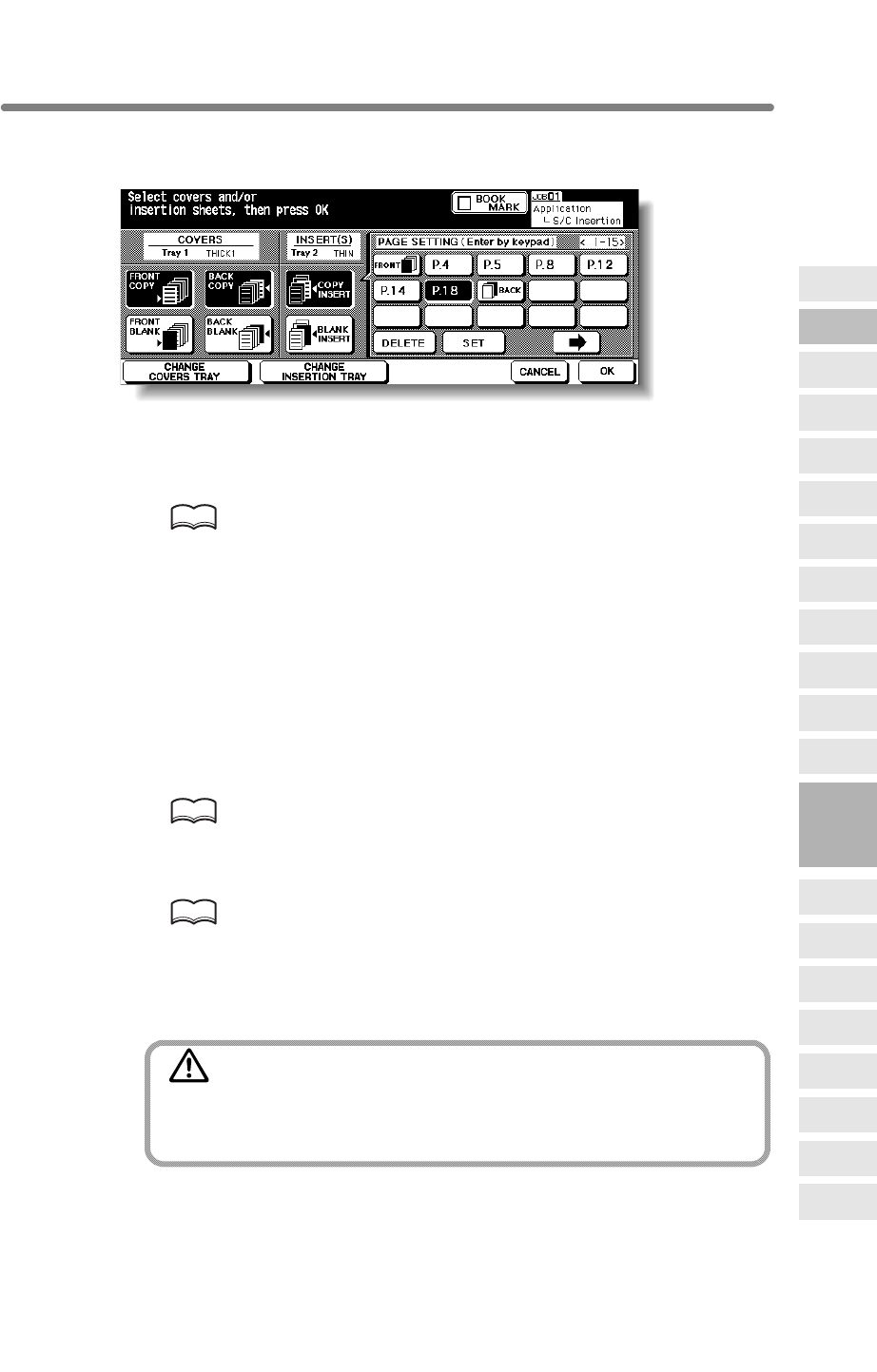
Inserting Sheets and Covers (Sheet/Cover Insertion) (continued)
9-5
6. When selecting Insertion mode:
Enter the page number.
Touch to select the desired insertion mode, then use the control panel keypad to enter
the page number of insertion location.
Touch SET after each entry to move to the next key.
To clear an incorrect entry, touch DELETE. The insertion location will be deleted.
HINT
See p. 9-6 for details on entering page numbers.
7. Touch CHANGE INSERTION TRAY to select the insertion tray source.
The tray source for covers currently selected is displayed on the Sheet/Cover Insertion
Screen.
Every touch of the key shifts the selection in the display that includes paper type as
specified in Key Operator mode.
8.
When all settings are completed, touch OK to return to the Basic
Screen.
9. Enter the desired print quantity from the control panel keypad.
HINT
See p. 3-7 for details on setting print quantity.
10. Position originals FACE UP in the document feeder.
HINTS
• For details on positioning originals, see p. 3-2.
•
exceeds 100.
11. Press [START].
CAUTION
When the finisher / paper exit tray capacity is exceeded due to
the print quantity selected, remove the copied sets as they exit;
otherwise, mishandled paper will occur.
9
Applications
Reverse
Image
Non-Image
Area Erase
Program Job
Dual Page
Image Insert
OHP
Interleave
Booklet
Combination
Chapter
Sheet/Cover
Insertion
Application
Selection Screen
Repeat
Frame/Fold
Erasure
AUTO
Layout
Full-Image
Area
Image Shift
Reduce &
Shift
Stamp
Overlay
Overlay
Memory
Use RADF store mode (p. 3-32 to p. 3-33) when the original count

Inserting Sheets and Covers (Sheet/Cover Insertion) (continued)
9-6
DETAILS: Entering Page Numbers
Fifteen keys are displayed on the screen to designate each insertion
location. When setting more than 15 locations, touch the arrow key to move
to the next page.
The first (upper left) key displays the Front Cover icon if selected. The Back
Cover icon appears, if selected, as the last (fixed) key, with one active blank
key preceding it.
Example: If p. 4 is entered in blank mode, a blank sheet will be inserted
between p. 4 and p. 5; in copy mode, a copied sheet is inserted at p. 4.
NOTES:
• The page numbers entered at random will be sorted automatically.
• Entering “0” or the same page number twice will be ignored on the
screen.
• When a page number entered is larger than the total original page count,
it will be ignored.
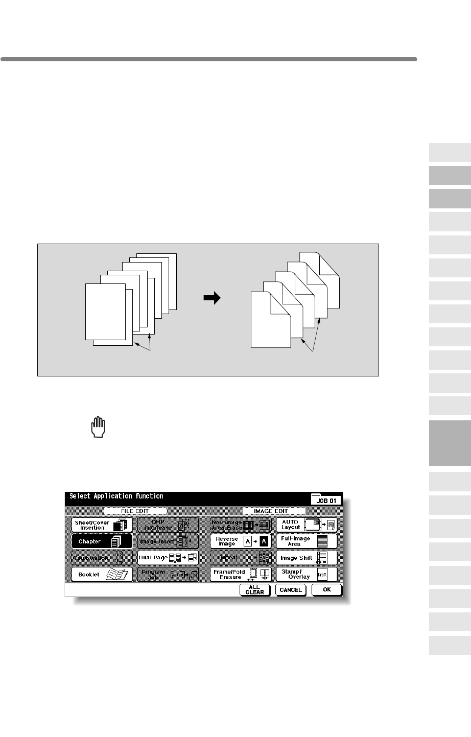
9-7
Locating Title Pages on the Right Side (Chapter)
To effectively locate the title page on the right, a blank sheet will be automatically
created on the reverse side of a sheet, if required.
>>>Specifications for Chapter<<<
❒Max. title pages: 30 sheets, from 1 ~ 999
❒
Use STAMP together with this function to print chapter number onto chapter page in
addition to page number, numbering, or watermark numbering. See p. 9-50 to p. 9-58.
Face Up, Mixed Original, Tab Paper, Combination, OHP Interleave, Image Insert,
Program Job, Non-Image Area Erase, Repeat, Storing Image in Overlay Memory
1. Touch APPLICATION on the Basic Screen.
Reminder!
press [AUTO RESET].
2. Touch Chapter on the Application Selection Screen.
The Chapter Insertion Setting No. Screen will be displayed.
8
4
6
2
5
1
8
1
7
6
5
4
3
2
Title pages
Title pages
1-sided originals Copies in
Chapter mode
3
7
9
Applications
Reverse
Image
Non-Image
Area Erase
Program Job
Dual Page
Image Insert
OHP
Interleave
Booklet
Combination
Chapter
Sheet/Cover
Insertion
Application
Selection Screen
Repeat
Frame/Fold
Erasure
AUTO
Layout
Full-Image
Area
Image Shift
Reduce &
Shift
Stamp
Overlay
Overlay
Memory
right side, rather than reverse side, of a duplex copy to improve the presentation of
double-sided copies.
❒Use RADF.
When starting a new copying job, be sure to close the RADF securely, then
Chapter is used with RADF in 1u2 mode for the purpose of locating title pages on the
❒The HCI cannot be selected as tray source if specified as Thick 3.
❒Incompatible Conditions: 1u1, 2u1, Group, Rotation Sort, Rotation Group,
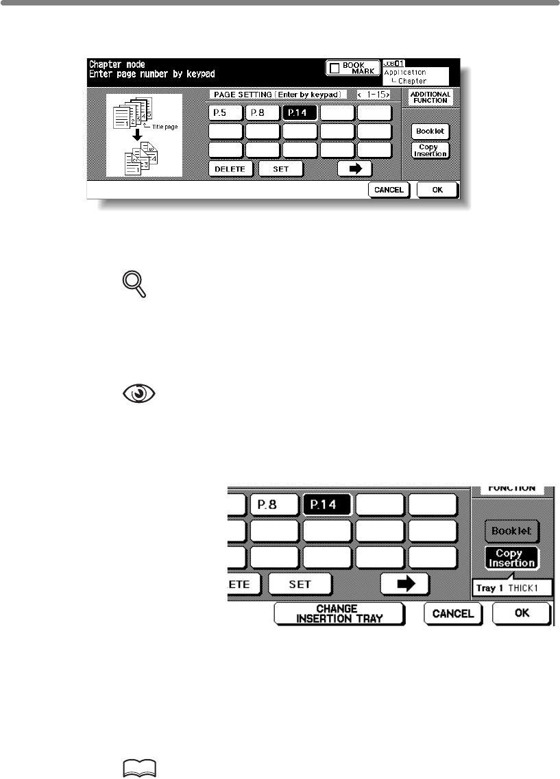
Locating Title Pages on the Right Side (Chapter) (continued)
9-8
3. Use the control panel keypad to enter the page number of each title
page.
Touch SET after each entry to move to the next key.
When setting more than 15 locations, touch the arrow key to move to the next page.
To clear an incorrect entry, touch DELETE. The entered number will be deleted.
DETAILS
• Entering “0” or the same page number twice will be ignored on the
screen.
• Chapter insertions occur in sequence even if original page numbers are
entered out of sequence.
• When a page number is larger than the total original page count,
insertion occurs as the last page of the document.
OPTION
Touch Booklet on the Chapter Insertion Setting No. Screen to use this
function.
To change the selection of paper tray for copying title pages, touch Copy
Insertion on the screen. In this case, you can touch CHANGE INSERTION
TRAY to change the currently selected paper tray displayed on the screen.
4. When all entries are made, touch OK.
The Application Selection Screen will be restored.
5. Touch OK on the Application Selection Screen.
The Basic Screen will be restored.
6. Enter the desired print quantity from the control panel keypad.
HINT
See p. 3-7 for details on setting print quantity.

Locating Title Pages on the Right Side (Chapter) (continued)
9-9
7. Position originals FACE UP in the document feeder.
HINTS
•
•
exceeds 100.
8. Press [START].
CAUTION
When the finisher / trimmer unit / paper exit tray capacity is
exceeded due to the print quantity selected, remove the copied
sets as they exit; otherwise, mishandled paper will occur.
9
Applications
Reverse
Image
Non-Image
Area Erase
Program Job
Dual Page
Image Insert
OHP
Interleave
Booklet
Combination
Chapter
Sheet/Cover
Insertion
Application
Selection Screen
Repeat
Frame/Fold
Erasure
AUTO
Layout
Full-Image
Area
Image Shift
Reduce &
Shift
Stamp
Overlay
Overlay
Memory
For details on positioning originals, see p. 3-2 to p. 3-5.
Use RADF store mode (p. 3-32 to p. 3-33) when the original count
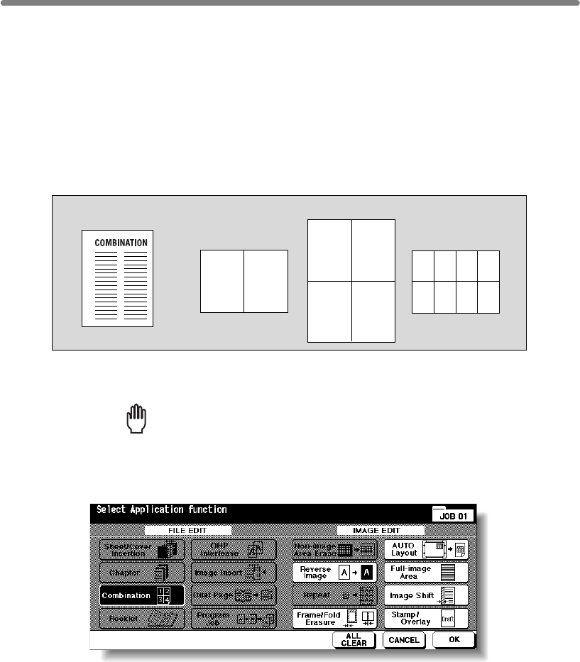
9-10
Lay Out Several Pages onto One Sheet (Combination)
Use this function to lay out and copy a fixed number (2, 4, or 8) of pages onto one sheet
of copy paper (2 in 1, 4 in 1, or 8 in 1).
>>>Specifications for Combination<<<
❒AMS is automatically selected. (Normally the fixed size of Tray 1 will be selected.)
❒
Incompatible Conditions: APS, Group, Rotation Sort, Rotation Group, Fold/ Stitch&Fold/
Trimming (with Booklet selected), Mixed Original, Sheet/Cover Insertion, Chapter, Booklet,
OHP Interleave, Image Insert, Dual Page, Program Job, Non-Image Area Erase, Repeat,
Storing Image in Overlay Memory
1. Touch APPLICATION on the Basic Screen.
Reminder!
press [AUTO RESET].
2. Touch Combination on the Application Selection Screen.
The Combination Mode Selection Screen will be displayed.
12
12
34
1
5
2
6
3
7
4
8
Original
2 in 1 copying
4 in 1 copying
8 in 1 copying
❒Use RADF.
When starting a new copying job, be sure to close the RADF securely, then
❒The HCI cannot be selected as tray source if specified as Thick 3.

Lay Out Several Pages onto One Sheet (Combination) (continued)
9-11
3. Select the desired Combination mode.
Touch 2 in 1, 4 in 1 or 8 in 1 in the desired order area, referring to the illustration on
the following page.
4. Touch OK.
The Application Selection Screen will be restored.
5. Touch OK on the Application Selection Screen.
The Basic Screen will be restored.
AMS is automatically selected. When selecting any tray other than the one that is set
and displayed on the Basic Screen, touch the desired tray key.
6. Select the desired original direction.
Touch SPECIAL ORIGINAL on the Basic Screen to display the Special Original popup
menu. Touch to select the desired original direction, then touch OK to return to the
Basic Screen.
7. Enter the desired print quantity from the control panel keypad.
HINT
See p. 3-7 for details on setting print quantity.
9
Applications
Reverse
Image
Non-Image
Area Erase
Program Job
Dual Page
Image Insert
OHP
Interleave
Booklet
Combination
Chapter
Sheet/Cover
Insertion
Application
Selection Screen
Repeat
Frame/Fold
Erasure
AUTO
Layout
Full-Image
Area
Image Shift
Reduce &
Shift
Stamp
Overlay
Overlay
Memory
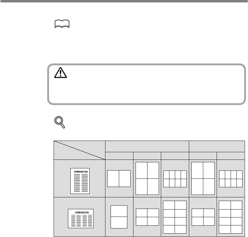
Lay Out Several Pages onto One Sheet (Combination) (continued)
9-12
8. Position originals FACE UP in the document feeder.
HINTS
• For details on positioning originals, see p. 3-2 to p. 3-5.
•
9. Press [START].
CAUTION
When the finisher / paper exit tray capacity is exceeded due to
the print quantity selected, remove the copied sets as they exit;
otherwise, mishandled paper will occur.
DETAILS: Original Type and Layout Order
Refer to the table below to select the desired Combination mode.
12
1
2
12
34
1
5
2
6
3
7
4
8
12
34
12
34
56
78
13
24
1
2
3
4
5
6
7
8
13
24
15
26
37
48
2 in 1 4 in 1 8 in 1 4 in 1 8 in 1
Portrait type
Landscape type
Original
Layout Horizontal order Vertical order
exceeds 100.
Use RADF store mode (p. 3-32 to p. 3-33) when the original count
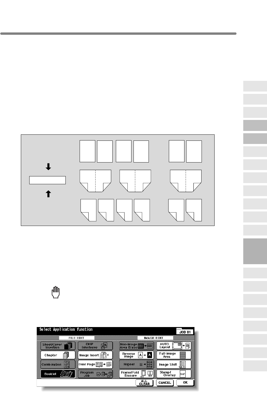
9-13
Making a Multiple Page Signature Booklet (Booklet)
Use the Booklet function to make a multiple page signature booklet copied on both
sides of the paper from any tray unless it is specified as Thick or Tab paper of the paper
type in the Key Operator mode. Original images are scanned into memory and
automatically arranged in booklet format in the correct order.
>>>Specifications for Booklet<<<
❒Original pages should be a multiple of 4 in 1-2 mode or a multiple of 2 in 2-2 mode;
otherwise blank pages are automatically inserted to the last.
❒AMS is automatically selected. Select the desired paper size.
Face Up, Cover sheet feeder with Cover mode in Booklet, Mixed Original, Tab
Paper, Sheet/Cover Insertion, Combination, OHP Interleave, Program Job, Non-
Image Area Erase, Repeat, Storing Image in Overlay Memory
1. Load Copy Paper.
Load the desired copy paper size in a tray.
When selecting cover sheet mode (Cover with Copy sheet or Cover with Blank
sheet), load the same size paper in any other tray unless it is specified as Thick or Tab
paper of the paper type in the Key Operator mode.
2. Touch APPLICATION on the Basic Screen.
Reminder!
press [AUTO RESET].
3. Touch Booklet on the Application Selection Screen.
123447 48
..............
..............
2
47
148
4
45
346
24
25
2326
1-sided originals
2-sided originals ..............
2
1
4
3
6
5
8
7
46
45
48
47
Booklet copying
9
Applications
Reverse
Image
Non-Image
Area Erase
Program Job
Dual Page
Image Insert
OHP
Interleave
Booklet
Combination
Chapter
Sheet/Cover
Insertion
Application
Selection Screen
Repeat
Frame/Fold
Erasure
AUTO
Layout
Full-Image
Area
Image Shift
Reduce &
Shift
Stamp
Overlay
Overlay
Memory
❒Use RADF.
When starting a new copying job, be sure to close the RADF securely, then
❒Incompatible Conditions: APS, 1u1, 2u1, Group, Rotation Sort, Rotation Group,
❒The HCI cannot be selected as tray source if specified as Thick 3.
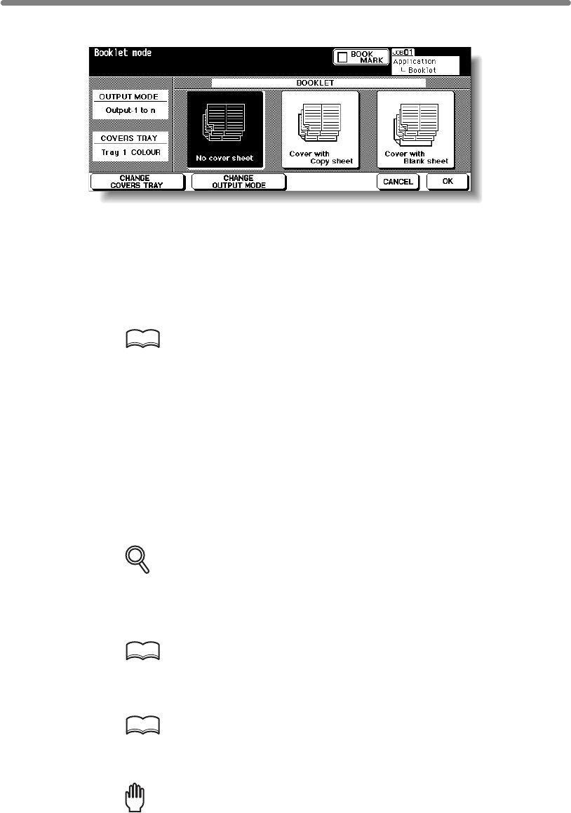
Making a Multiple Page Signature Booklet (Booklet) (continued)
9-14
4. Touch to highlight the desired Booklet mode key.
When a cover sheet is required, touch CHANGE COVERS TRAY to select the cover
sheet tray source.
Touch CHANGE OUTPUT MODE is you want to change the output order.
5. Touch OK.
The Application Selection Screen will be restored.
Select additional Applications, as desired.
HINT
Key Operator can set the machine to position the page numbers
automatically on the outside edges of the copy when using Booklet with
Page Numbing in Stamp. See p. 13-39 to p. 13-44.
6. Touch OK on the Application Selection Screen.
The Basic Screen will be restored.
AMS is selected automatically.
7. Select the tray in which you loaded copy paper in step 1.
To release AMS, select the desired magnification, then select paper size.
8.
DETAILS
9. Enter the desired print quantity from the control panel keypad.
HINT
See p. 3-7 for details on setting print quantity.
10. Position originals FACE UP in the document feeder.
HINTS
•
•
exceeds 100.
Reminder!
Original pages should be a multiple of 4 in 1-2 mode or a multiple of 2 in 2-2
mode; otherwise blank pages are automatically inserted to the last.
output mode is available. Follow the procedure on p. 9-15 to use the
function.
For details on positioning originals, see p. 3-2 to p. 3-5.
Use RADF store mode (p. 3-32 to p. 3-33) when the original count
Select the 1u2 or 2u2 copy mode.
If the mfp is equipped with Q3220A Finisher, Fold or Stitch & Fold
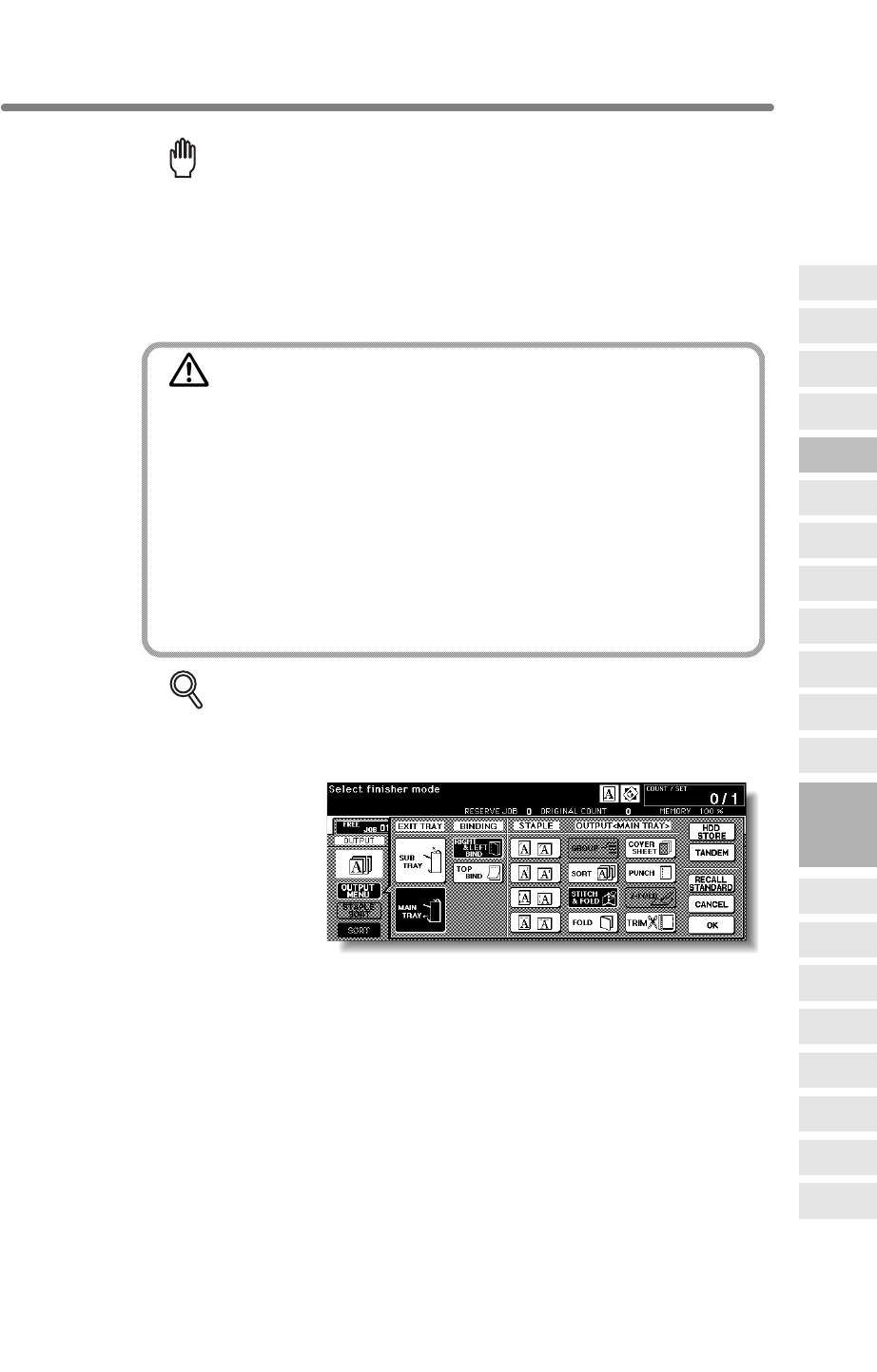
Making a Multiple Page Signature Booklet (Booklet) (continued)
9-15
Reminder!
When loading originals, heed the following limits on capacity:
Fold mode 12 pages or less for simplex copying
6 pages or less for duplex copying
Stitch & Fold mode 80 pages or less for simplex copying
40 pages or less for duplex copying
Exeeding the above limits on capacity may cause misfeeds in the finisher.
11. Press [START].
CAUTION
When the finisher / paper exit tray capacity is exceeded due to
the print quantity selected, remove the copied sets as they exit;
otherwise, mishandled paper will occur.
When the Booklet / Trimmer unit tray capacity is exceeded, the
finisher / trimmer unit will cease operating. To avoid such
trouble, select an appropriate print quantity from the
specifications on p. 11-3.
The roller drive unit is located inside the Booklet tray of the
finisher. DO NOT put your hand into the roller drive unit when
removing folded or stapled & folded sheets; otherwise, you may
be injured.
DETAILS: Selecting Fold / Stitch & Fold Mode
1Touch OUTPUT MENU on the Basic Screen to display the Output Mode
popup menu, then touch MAIN TRAY to highlight it.
2Touch STITCH & FOLD or FOLD, as desired.
NOTE:
Selecting FOLD or STITCH & FOLD will automatically switch the output
tray to Booklet tray. Notice that the arrow shown beside the Main tray
shifts to the Booklet tray.
3Touch OK on the Output Mode popup menu. The Basic Screen will be
restored with the OUTPUT MENU highlighted.
9
Applications
Reverse
Image
Non-Image
Area Erase
Program Job
Dual Page
Image Insert
OHP
Interleave
Booklet
Combination
Chapter
Sheet/Cover
Insertion
Application
Selection Screen
Repeat
Frame/Fold
Erasure
AUTO
Layout
Full-Image
Area
Image Shift
Reduce &
Shift
Stamp
Overlay
Overlay
Memory
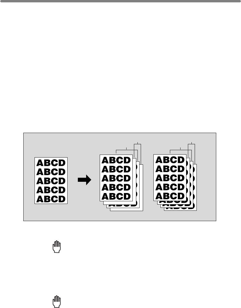
9-16
Copying onto Transparent Films (OHP Interleave)
transparent films, and output a blank or copied interleaf sheet with each copied
transparent film.
In the Blank sheet interleaving mode, a blank interleaf sheet is output with each
transparent film to keep the film material from sticking together.
In the Copy sheet interleaving mode, a copied interleaf sheet is output with each
transparent film to provide reference during a presentation, a medium for photocopying,
and a set for filing or inserting into a binder.
>>>Specifications for OHP Interleave<<<
❒Transparent film source: Multi-sheet bypass tray
❒Print quantity: 1
❒Finisher cannot be used.
❒AMS is automatically selected.
Rotation Group, Fold, Stitch & Fold, Trimming, Cover sheet feeding, Punch, Mixed
Original, Tab Paper, Sheet/Cover Insertion, Chapter, Combination, Booklet, Image
Insert, Program Job, Repeat, Overlay, Storing Image in Overlay Memory, Tandem
mode
1. Insert a sheet of transparent film into the Multi-sheet bypass tray.
Reminder!
Do not load transparent films into any other tray.
2. When interleaf sheet is needed, load copy paper in any other tray to
match the size of transparent films.
3. Touch APPLICATION on the Basic Screen.
Reminder!
press [AUTO RESET].
Copy Sheet Interleaving
Blank Sheet Interleaving
Original
Blank interleaf sheets
Transparent films
Copied interleaf sheets
Transparent films
When starting a new copying job, be sure to close the RADF securely, then
❒Incompatible Conditions: APS, 1u2, 2u2, Sort, Staple-sort, Group, Rotation Sort,
Use the OHP Interleave function in 1u1 or 2u1 mode to copy onto overhead projection
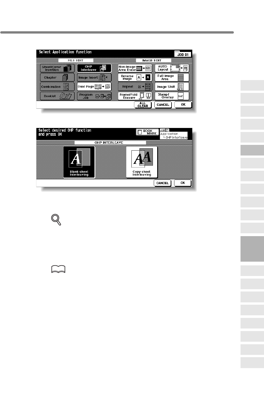
Copying onto Transparent Films (OHP Interleave) (continued)
9-17
4. Touch OHP Interleave on the Application Selection Screen.
5. Select the desired OHP Interleave mode, then touch OK.
6. Touch OK on the Application Selection Screen.
The Basic Screen will be restored.
DETAILS
• AMS is selected automatically.
To release AMS, select the desired magnification.
• Print quantity is already set to 1. You cannot enter any other quantity.
7. Position original(s) FACE UP in the document feeder or FACE DOWN
on the platen glass.
HINTS
For details on positioning originals, see p. 3-2 to p. 3-6.
8. Press [START].
9
Applications
Reverse
Image
Non-Image
Area Erase
Program Job
Dual Page
Image Insert
OHP
Interleave
Booklet
Combination
Chapter
Sheet/Cover
Insertion
Application
Selection Screen
Repeat
Frame/Fold
Erasure
AUTO
Layout
Full-Image
Area
Image Shift
Reduce &
Shift
Stamp
Overlay
Overlay
Memory
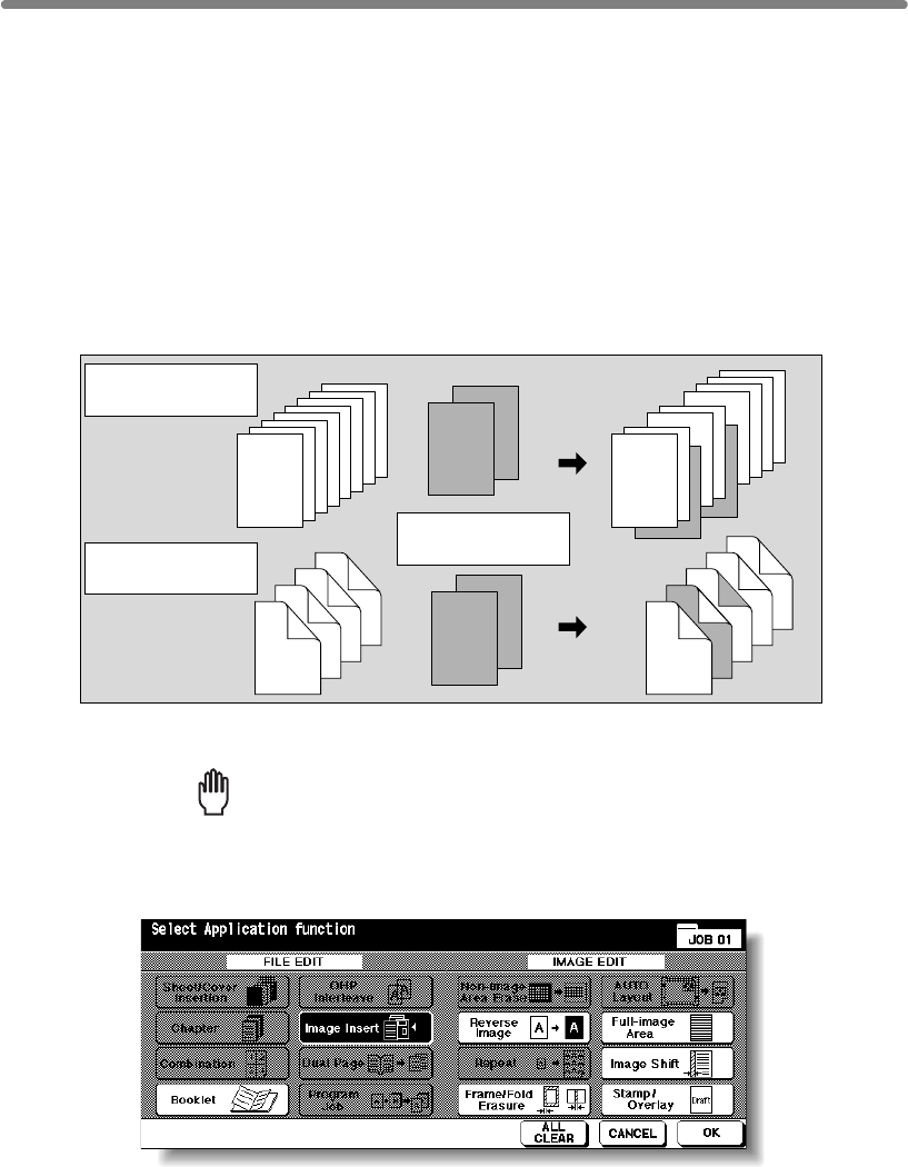
9-18
Inserting Images into Printed Sets (Image Insert)
Use the Image insert mode to combine images scanned from the platen glass, such as
photos, paste-ups, newspaper articles, graphs, etc., with images scanned from the
document feeder. Then, output the combined images as a finished set.
The selected copy paper size is determined by the size of originals loaded in the
document feeder.
>>>Specifications for Image Insert<<<
❒Max. image insert: 30 locations, from p. 1 to p. 999
❒Incompatible Conditions: Group, Rotation Sort, Rotation Group, Mixed Original, Tab
Paper, Sheet/Cover Insertion, Chapter, Combination, OHP Interleave, Dual Page,
Program Job, Non-image Area Erase, Repeat, AUTO Layout, Overlay, Storing
Image in Overlay Memory
1. Touch APPLICATION on the Basic Screen.
Reminder!
press [AUTO RESET].
2. Touch Image Insert on the Application Selection Screen.
The Image Insertion No. Setting Screen will be displayed.
1-sided originals
2-sided originals
5
6
7
8
2
4
1
3
7
8
4
5
2
3
1
6
8
1
7
6
5
4
3
2
8
7
6
1
5
4
3
2
Insertion originals
on platen glass
❒Use RADF and platen glass.
placed on RADF
placed on RADF
When starting a new copying job, be sure to close the RADF securely, then
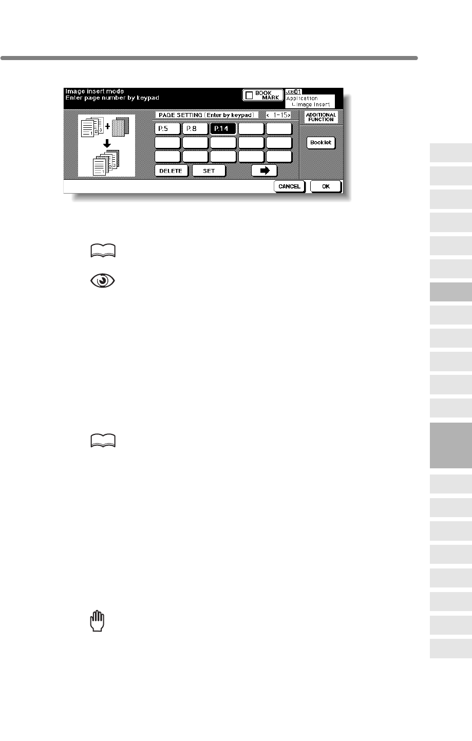
Inserting Images into Printed Sets (Image Insert) (continued)
9-19
3. Use the control panel keypad to enter the page number.
Touch SET after each entry to move to the next key.
When setting more than 15 locations, touch the arrow key to move to the next page.
To clear an incorrect entry, touch DELETE. The entered page number will be deleted.
HINT
See p. 9-20 for detailed example.
OPTION
Touch Booklet on the Image Insertion No. Setting Screen to use this
function.
4. When all page number entries are made, touch OK.
The Application Selection Screen will be restored.
5. Touch OK on the Application Selection Screen.
The Basic Screen will be restored.
The STORE key on the Basic Screen appears highlighted to show that the Store mode
is automatically selected.
6. Enter the desired print quantity from the control panel keypad.
HINT
See p. 3-7 for details on setting print quantity.
7. Scan the document feeder images:
Position originals FACE UP in the document feeder.
If the number of originals exceeds 100, divide them into blocks not exceeding 100
sheets and load them from the block with the first page.
8. Press [START].
The originals positioned in the document feeder will be scanned into memory.
9. Scan the platen glass images.
Open the document feeder.
Position an original FACE DOWN on the platen glass, then close the document feeder.
Reminder!
PLACE AND SCAN THE ORIGINALS ACCORDING TO PAGINATION.
10. Press [START].
9
Applications
Reverse
Image
Non-Image
Area Erase
Program Job
Dual Page
Image Insert
OHP
Interleave
Booklet
Combination
Chapter
Sheet/Cover
Insertion
Application
Selection Screen
Repeat
Frame/Fold
Erasure
AUTO
Layout
Full-Image
Area
Image Shift
Reduce &
Shift
Stamp
Overlay
Overlay
Memory
Inserting Images into Printed Sets (Image Insert) (continued)
9-20
11. Repeat steps 9 and 10 for all originals.
HINTS
• Memory overflow may occur during scanning. See p. 5-11 to p. 5-12.
• Should memory overflow occur frequently, it is recommended that you
contact your service representative to extend the memory capacity in
your machine.
12. Touch STORE to exit the Store mode.
13. Press [START].
CAUTION
When the finisher / trimmer unit / paper exit tray capacity is
exceeded due to the print quantity selected, remove the copied
sets as they exit; otherwise, mishandled paper will occur.
DETAILS: Entering Page Numbers
For example, if insertion locations are [2/2/6], scanned platen images will be
inserted as follows:
The first scanned platen image will be inserted after page 2.
The second scanned platen image will be inserted directly after the first
scanned Image insertion.
The third scanned platen image will be inserted after page 6.
NOTES:
• When a page number is larger than the total original count, a sheet is
inserted as the last page.
• Insertions occur in sequence, even if page numbers are entered out of
sequence.
• Entering the same page number twice will insert two sheets at that
location.
The mfp will start printing when ready for output.
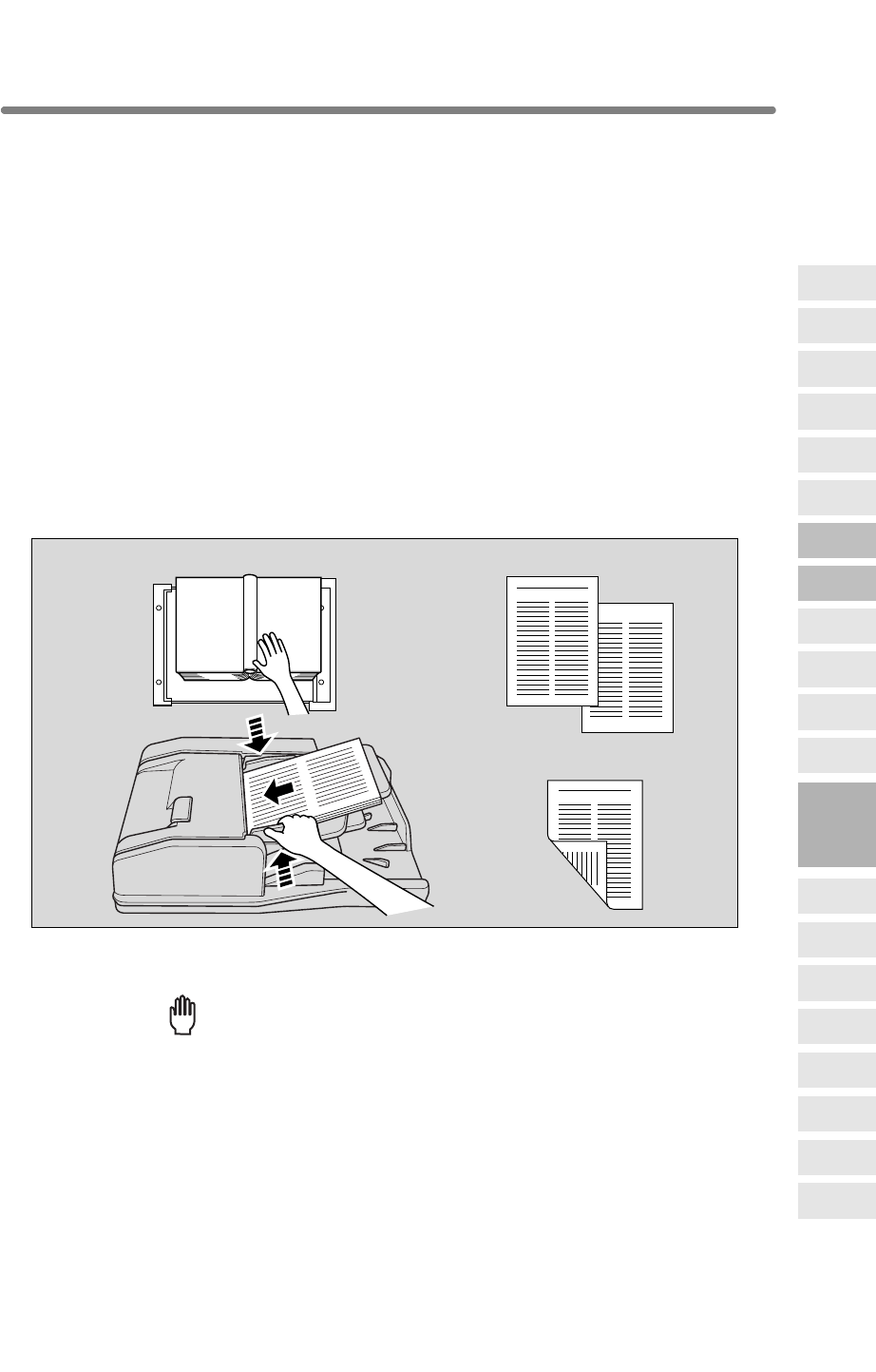
9-21
Dividing an Image into Right and Left Pages (Dual Page)
The Dual Page mode performs image division on the original image.
Use this function to copy an open book or a A3/B4 size sheet onto two A4/B5 sheets in
mode.
The following three modes can be selected from the Dual Page Screen.
•Facing Pages mode: Image division starts from the first scan.
•Front Cover+Facing Pages mode: Image division starts from the second scan, after
the first scan copies normally.
•Front/Back Cover+Facing Pages mode: Image division starts from the third scan,
after the first and second scan copy normally.
>>>Specifications for Dual Page<<<
❒Store mode is automatically selected.
❒Paper size: A4, B5
❒
Incompatible Conditions: APS, AMS, Rotation Sort, Rotation Group, Fold (compatible
with Booklet selected), Stitch&Fold (compatible with Booklet selected), Trimming, Mixed
Original, Tab Paper, Sheet/Cover Insertion, Combination, Image Insert, Program Job,
Repeat, Reduce & Shift in Image Shift, Overlay, Storing Image in Overlay Memory
1. Touch APPLICATION on the Basic Screen.
Reminder!
press [AUTO RESET].
Set original
1-2 / 2-2 mode
1-1 / 2-1 mode
9
Applications
Reverse
Image
Non-Image
Area Erase
Program Job
Dual Page
Image Insert
OHP
Interleave
Booklet
Combination
Chapter
Sheet/Cover
Insertion
Application
Selection Screen
Repeat
Frame/Fold
Erasure
AUTO
Layout
Full-Image
Area
Image Shift
Reduce &
Shift
Stamp
Overlay
Overlay
Memory
When starting a new copying job, be sure to close the RADF securely, then
1u1 or 2u1 mode, or onto the front and back sides of one A4/B5 sheet in 1u2 or 2u2
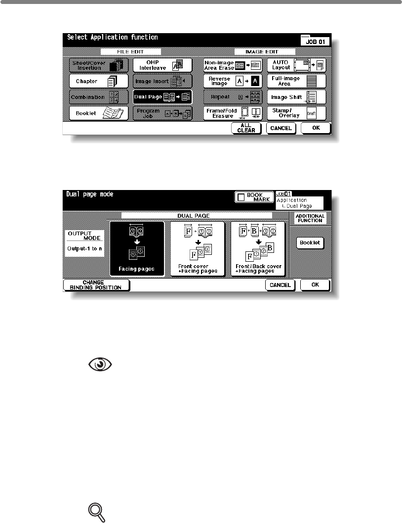
Dividing an Image into Right and Left Pages (Dual Page) (continued)
9-22
2. Touch Dual Page on the Application Selection Screen.
The Dual Page Screen will be displayed.
3. Select the desired Dual Page mode.
Touch to highlight the desired mode key.
4. Touch CHANGE BINDING POSITION to select the output order
according to the original pagenation.
OPTION
Touch Booklet on the Dual Page Screen to use this function.
5. Touch OK.
The Application Selection Screen will be restored.
6. Touch OK on the Application Selection Screen.
The Basic Screen will be restored.
APS and AMS are automatically released, and the STORE key appears highlighted to
show that the Store mode is automatically selected.
7. Select the desired copy mode and magnification.
DETAILS
• Available paper size is A4 or B5.
• When selecting Facing Pages mode and scanning from the platen glass,
• APS and AMS are released and 1.00 magnification is selected automati-
cally. Change the magnification manually, if desired.
select 1u1 or 1u2 copy mode.
Dividing an Image into Right and Left Pages (Dual Page) (continued)
9-23
8. Enter the desired print quantity from the control panel keypad.
HINT
See p. 3-7 for details on setting print quantity.
9. Position original(s).
When using platen glass to scan, position the first page FACE DOWN with document
feeder kept open.
When using document feeder, position original(s) FACE UP.
For details on scanning originals in Front cover + Facing pages and Front/Back Cover
+ Facing pages mode, see the description on the following page.
10. Press [START] to scan.
11. Repeat steps 9 and 10 for all originals.
Reminder!
When using platen glass, Non-Image Area Erase and AUTO Layout are
automatically selected.
DO NOT CLOSE the document feeder throughout the scanning job.
12. Touch STORE to exit the Store mode.
13. Press [START].
CAUTION
When the finisher / paper exit tray capacity is exceeded due to
the print quantity selected, remove the copied sets as they exit;
otherwise, mishandled paper will occur.
9
Applications
Reverse
Image
Non-Image
Area Erase
Program Job
Dual Page
Image Insert
OHP
Interleave
Booklet
Combination
Chapter
Sheet/Cover
Insertion
Application
Selection Screen
Repeat
Frame/Fold
Erasure
AUTO
Layout
Full-Image
Area
Image Shift
Reduce &
Shift
Stamp
Overlay
Overlay
Memory
The mfp will start printing when ready for output.
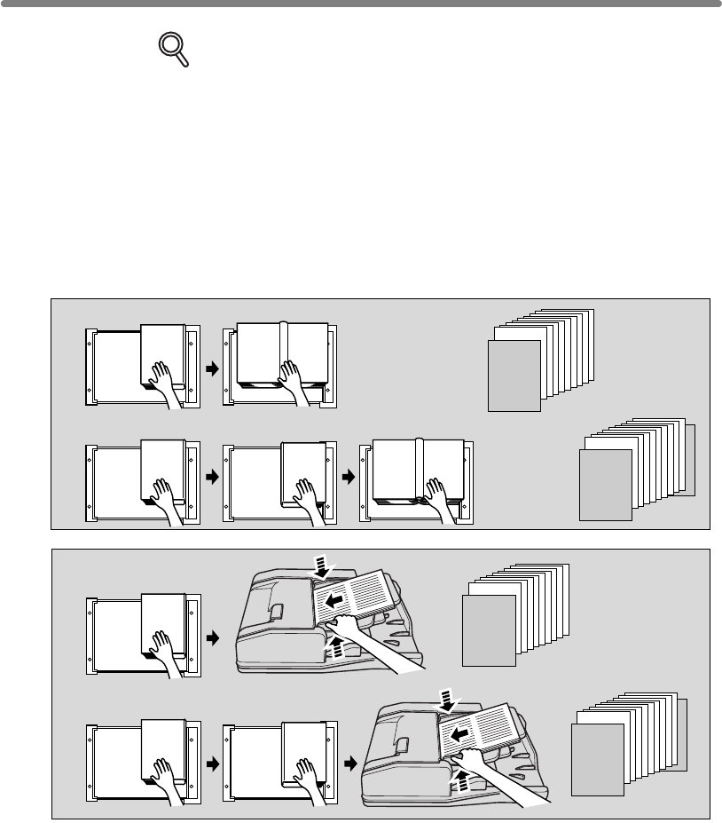
Dividing an Image into Right and Left Pages (Dual Page) (continued)
9-24
Scanning Original for Cover
Use platen glass for scanning original for cover.
1Open the document feeder.
2Position original for front cover FACE DOWN on the platen glass.
3Press [START] to start scanning.
4When Front/Back Cover + Facing Pages is selected, scan original for
back cover according to the above steps 2 and 3.
5Use platen glass or document feeder, as required, for scanning body text
originals.
To output the set in the same order as the originals, start scanning from
the first page.
6Press [START] to start scanning.
7Repeat steps 5 and 6 for subsequent originals.
NOTES:
• Memory overflow may occur during scanning. See p. 5-11 to p. 5-12.
• When using platen glass, Non-Image Area Erase and AUTO Layout are
automatically selected.
DO NOT CLOSE the document feeder throughout the scanning job.
“Front cover + Facing pages”
“Front/Back cover + Facing pages”
Scan from
first page
Scan from
first page
1
23456789
10
SURVEYOR’S
REPORT
1
23456789
10
SURVEYOR’S
REPORT
SURVEYOR’S
REPORT
SURVEYOR’S
REPORT
SURVEYOR’S
REPORT
Copies
Copies
1
23456789
10
SURVEYOR’S
REPORT
1
23456789
10
SURVEYOR’S
REPORT
SURVEYOR’S
REPORT
“Front cover + Facing pages”
“Front/Back cover + Facing pages”
Copies
Copies
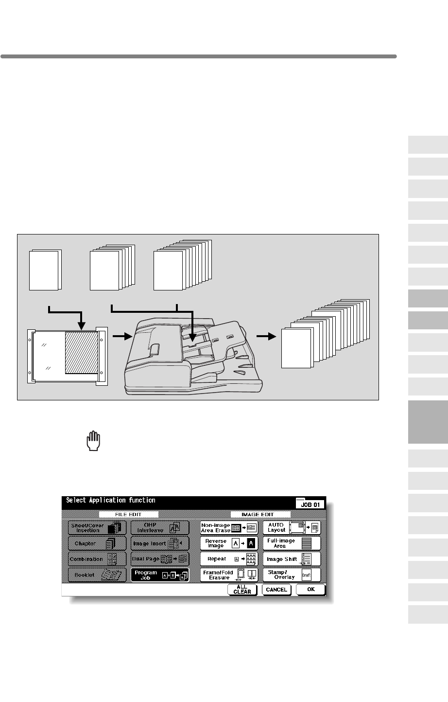
9-25
Programming Different Settings for an Output Job (Program Job)
In the ordinary Store mode, the combined features selected for the job are applied to all
originals to be scanned. In the Program Job mode, you may scan multiple sets of
originals and apply different settings on each set (referred to as JOB), then output them
all as a complete set.
>>>Specifications for Program Job<<<
❒Max. 100 JOBs can be programmed for an output job.
❒Once specified, paper size and the paper type/size setting for Multi-sheet bypass
tray cannot be changed for another JOB.
❒Output mode and print quantity setting cannot be specified for each JOB. The last
setting made will be applied to all JOBs.
❒Program Job settings cannot be stored in Job Memory.
❒Incompatible Conditions: APS, Change paper size, Rotation, Group, Rotation Sort,
Rotation Group, Fold, Stitch & Fold, Trimming, Server function, Mixed Original, Sheet/
Cover Insertion, Chapter, Combination, Booklet, OHP Interleave, Image Insert, Dual
Page, 2/4/8 Repeat in Repeat, Overlay, Storing Image in Overlay Memory
1. Touch APPLICATION on the Basic Screen.
Reminder!
press [AUTO RESET].
2. Touch Program Job on the Application Selection Screen.
The incompatible function keys will be dimmed to show inactivity.
3. Touch OK on the Application Selection Screen.
The Basic Screen will be restored.
The STORE key on the Basic Screen appears highlighted to show that the Store mode
is automatically selected.
123456789
10
123456
12
Original A
123456789
10
Original C
123456
Original B
12
Copied set
9
Applications
Reverse
Image
Non-Image
Area Erase
Program Job
Dual Page
Image Insert
OHP
Interleave
Booklet
Combination
Chapter
Sheet/Cover
Insertion
Application
Selection Screen
Repeat
Frame/Fold
Erasure
AUTO
Layout
Full-Image
Area
Image Shift
Reduce &
Shift
Stamp
Overlay
Overlay
Memory
When starting a new copying job, be sure to close the RADF securely, then
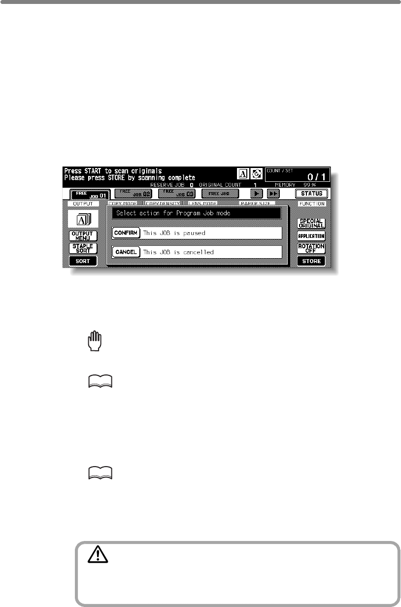
Programming Different Settings for an Output Job (Program Job) (continued)
9-26
4. Select the desired copy conditions.
5. Position originals FACE UP in the document feeder or FACE DOWN on
the platen glass.
If the number of document feeder originals exceeds 100, divide them into blocks not
exceeding 100 sheets and load them from the block with the first page.
6. Press [START].
The paper size determined at this time will be applied to all subsequent JOBs.
When scanning for the current JOB is completed, the popup menu will be displayed in
the Basic Screen.
7. Touch CONFIRM.
The current JOB images will be stored.
To delete the images, touch CANCEL.
8. Repeat steps 4 to 7 until all JOB originals are scanned.
Reminder!
PLACE AND SCAN EACH ORIGINAL SET IN THE CORRECT ORDER OF
PAGINATION.
HINTS
• Memory overflow may occur during scanning. See p. 5-11 to p. 5-12.
• Should memory overflow occur frequently, it is recommended that you
contact your service representative to extend the memory capacity in
your machine.
9. Select the desired output mode and enter the print quantity from the
control panel keypad.
HINT
See p. 3-7 for details on setting print quantity.
10. Touch STORE to exit the Store mode.
11. Press [START].
CAUTION
When the finisher / paper exit tray capacity is exceeded due to
the print quantity selected, remove the copied sets as they exit;
otherwise, mishandled paper will occur.
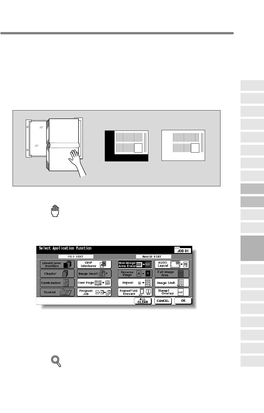
9-27
Erasing Outside of the Original (Non-Image Area Erase)
The Non-image area erase mode is used to copy non standard or special originals, such
as books, magazines, paste-ups, graphs, thick or thin materials, etc. from the platen glass.
The exposed glass area outside the borders of the original will not be copied.
>>>Specifications for Non-Image Area Erase<<<
Sort, Rotation Group, Fold, Stitch & Fold, Trimming, Mixed Original, Z-Folded
Original, Sheet/Cover Insertion, Chapter, Combination, Booklet, Image Insert, Dual
Image Shift, Storing Image in Overlay Memory
1. Touch APPLICATION on the Basic Screen.
Reminder!
press [AUTO RESET].
2.
Touch Non-image Area Erase on the Application Selection Screen.
The incompatible function keys will be dimmed to show inactivity.
3. Touch OK on the Application Selection Screen.
The Basic Screen will be restored.
4. Select magnification and paper size, as desired.
DETAILS
• APS and AMS are automatically released.
•
Platen store mode will function automatically.
Set original
General copying Non-Image Area Erase
9
Applications
Reverse
Image
Non-Image
Area Erase
Program Job
Dual Page
Image Insert
OHP
Interleave
Booklet
Combination
Chapter
Sheet/Cover
Insertion
Application
Selection Screen
Repeat
Frame/Fold
Erasure
AUTO
Layout
Full-Image
Area
Image Shift
Reduce &
Shift
Stamp
Overlay
Overlay
Memory
❒Use the platen glass only. Keep RADF open throughout the procedure.
Page in RADF Store mode, Reverse Image, Full-Image Area, Reduce & Shift in
When starting a new copying job, be sure to close the RADF securely, then
❒Incompatible Conditions: Using RADF, 2u2, 2u1, APS, AMS, Rotation, Rotation
Copy mode is automatically set to 1u1. When selecting 1u2 mode,
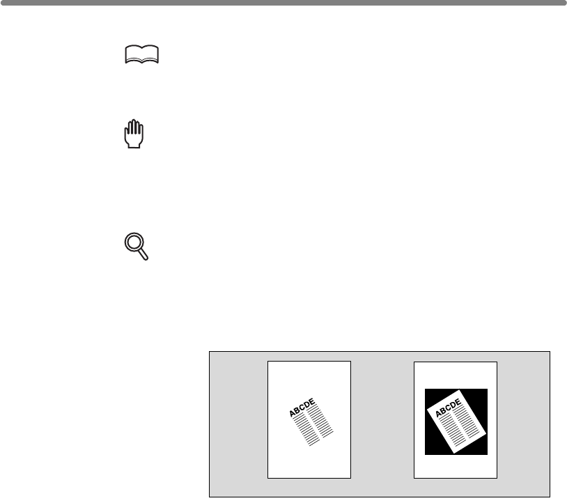
Erasing Outside of the Original (Non-Image Area Erase) (continued)
9-28
5. Enter the desired print quantity from the control panel keypad.
HINT
See p. 3-7 for details on setting print quantity.
6. Position original FACE DOWN on the platen glass.
Reminder!
DO NOT CLOSE THE DOCUMENT FEEDER.
Original size should be larger than 10mm x 10mm.
7. Press [START].
DETAILS: Oblique Erase and Rectangle Erase Modes
The Non-image area erase has two modes; Rectangle erase mode and
priate for the original placed on the platen glass (AUTO mode).
Key Operator can specify either mode and the original density level manu-
ally so that the Non-Image Area Erase functions without fail.
See p. 13-54.
Having Any Problem?
This function may perform incorrectly if the lighting in the work place is
directly over the platen glass. In this case, consult your service representa-
tive about an appropriate place for installation.
Rectangle erase mode
Oblique erase mode
Oblique erase mode. The mfp is initially set to select either mode appro-
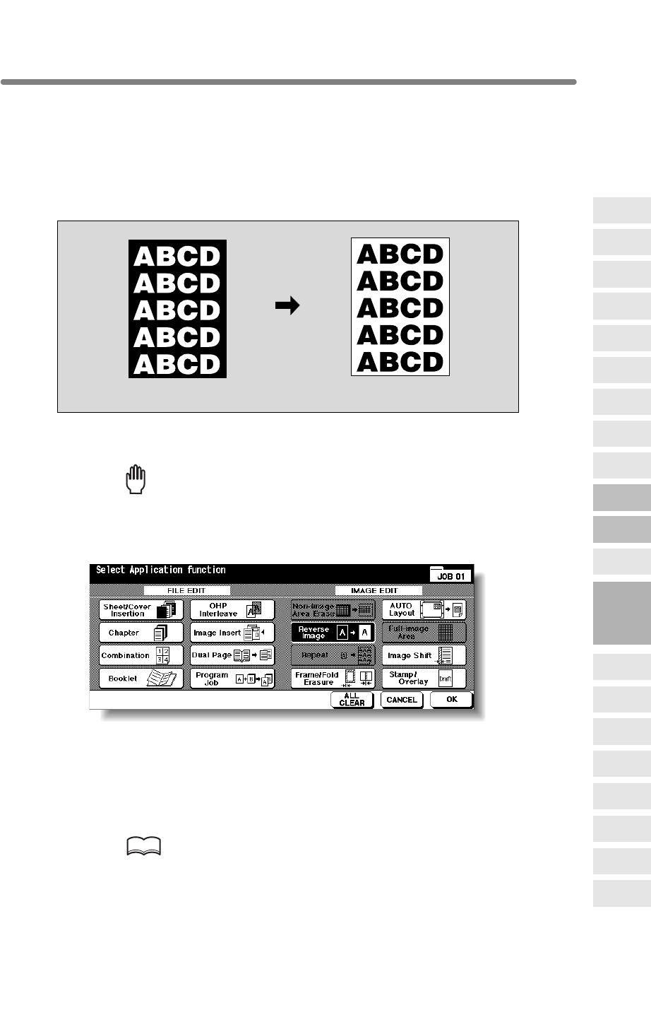
9-29
Use Reverse image to reverse the image from black-on-white to white-on-black, and
vice versa. This is very good for copying white-on-black originals and reversing them to
fax.
>>>Specifications for Reverse Image<<<
❒
Incompatible Conditions: Fold, Stitch & Fold, Trimming, Non-Image Area Erase, Repeat,
Full-Image Area, Stamp, Overlay
1. Touch APPLICATION on the Basic Screen.
Reminder!
press [AUTO RESET].
2. Touch Reverse Image on the Application Selection Screen.
The incompatible function keys will be dimmed to show inactivity.
3. Touch OK on the Application Selection Screen.
The Basic Screen will be restored.
4. Enter the desired print quantity from the control panel keypad.
HINT
See p. 3-7 for details on setting print quantity.
Original Reverse Image copying
9
Applications
Reverse
Image
Non-Image
Area Erase
Program Job
Dual Page
Image Insert
OHP
Interleave
Booklet
Combination
Chapter
Sheet/Cover
Insertion
Application
Selection Screen
Repeat
Frame/Fold
Erasure
AUTO
Layout
Full-Image
Area
Image Shift
Reduce &
Shift
Stamp
Overlay
Overlay
Memory
When starting a new copying job, be sure to close the RADF securely, then
Reversing Color in Black and White Image (Reverse Image)
9-30
5. Position original(s) FACE UP in the document feeder or FACE DOWN
on the platen glass.
HINT
For details on positioning originals, see p. 3-2 to p. 3-6.
6. Press [START].
CAUTION
When the finisher / paper exit tray capacity is exceeded due to
the print quantity selected, remove the copied sets as they exit;
otherwise, mishandled paper will occur.
Reversing Color in Black and White Image (Reverse Image) (continued)
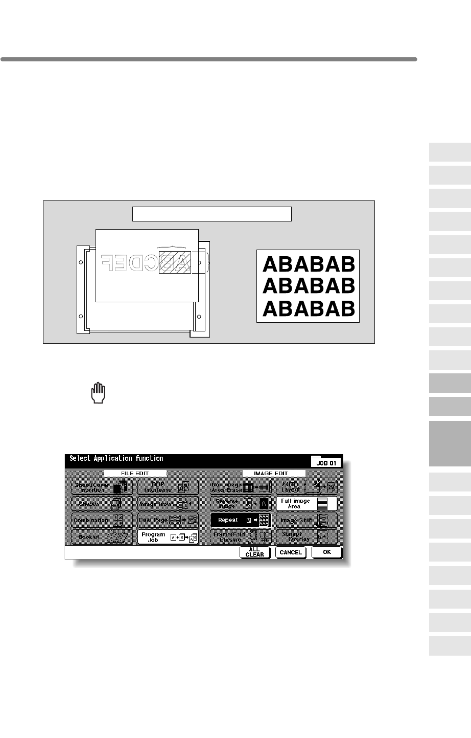
9-31
Repeating Selected Image Area (Repeat: Vert./Horiz. Mode)
Use this function to repeat the selected image area of 10mm ~ 150mm in both vertical
and horizontal widths measured from the rear right corner of the A3 original area
indicated on the right edge of the platen glass.
>>>Vertical/Horizontal Width Setting Mode Specifications<<<
❒Use the platen glass. (Document feeder cannot be used.)
Insertion, Chapter, Combination, Booklet, OHP Interleave, Image Insert, Dual Page,
Non-Image Area Erase, Frame/Fold Erasure, AUTO Layout, Reduce & Shift in
Image Shift, Stamp/Overlay
1. Touch APPLICATION on the Basic Screen.
Reminder!
press [AUTO RESET].
2. Touch Repeat on the Application Selection Screen.
The Repeat Mode Selection Screen will be displayed.
Vertical
width
Horizontal width Repeat copy
Vertical/Horizontal Width Setting mode
9
Applications
Reverse
Image
Non-Image
Area Erase
Program Job
Dual Page
Image Insert
OHP
Interleave
Booklet
Combination
Chapter
Sheet/Cover
Insertion
Application
Selection Screen
Repeat
Frame/Fold
Erasure
AUTO
Layout
Full-Image
Area
Image Shift
Reduce &
Shift
Stamp
Overlay
Overlay
Memory
Rotation Sort, Rotation Group, Mixed Original, Z-Folded Original, Sheet/Cover
When starting a new copying job, be sure to close the RADF securely, then
❒Incompatible Conditions: Using RADF, 2u2, 2u1, APS, AMS, Rotation, Group,
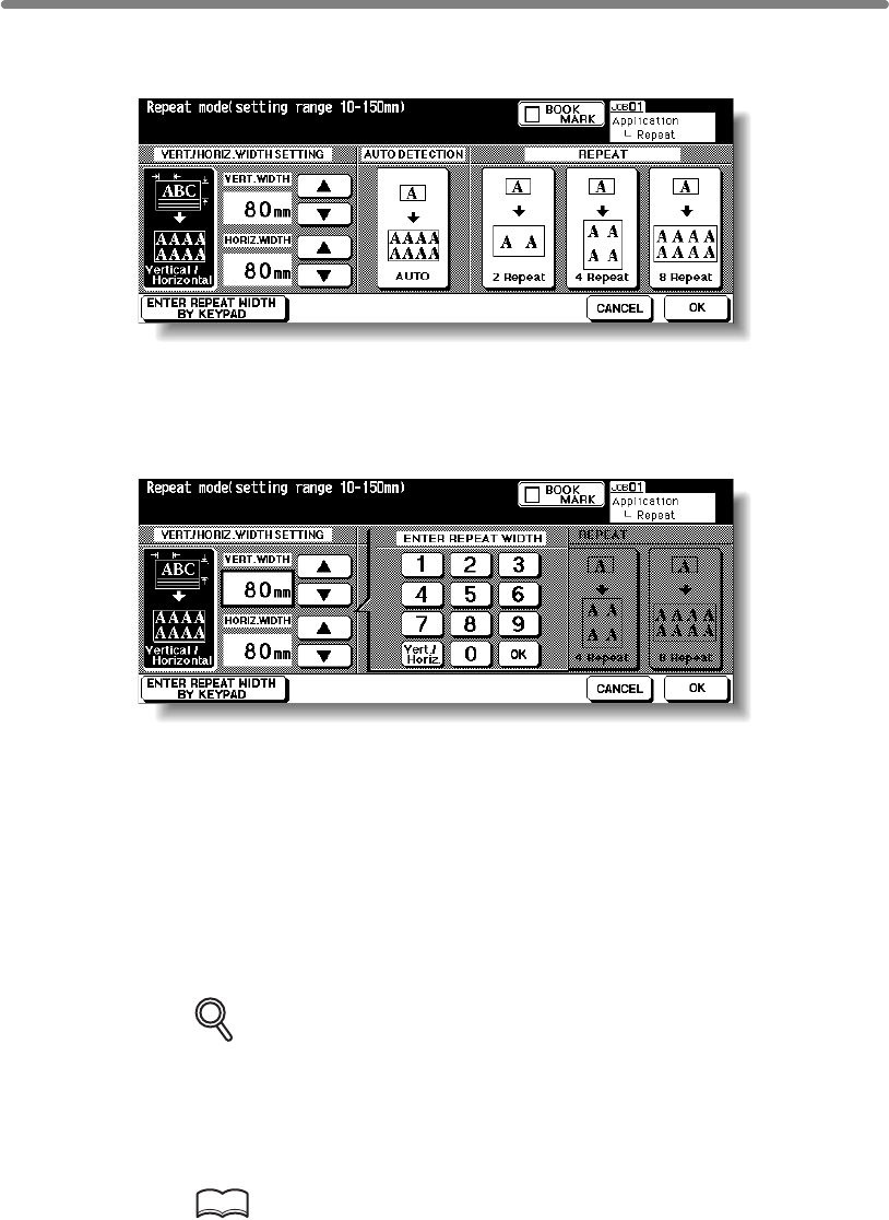
Repeating Selected Image Area (Repeat: Vert./Horiz. Mode) (continued)
9-32
3. Touch Vertical/Horizontal, then specify the vertical and horizontal
widths of the scanning area.
Use up/down arrow key to enter the width from 10 to 150mm in 1mm increments. Keep
touching the key to increase/decrease the value continuously.
Or, touch ENTER REPEAT WIDTH BY KEYPAD to display the popup menu to enter
the value from the touch screen keypad.
Touch Vert./Horiz. on the popup menu each time to shift it from one to another. Enter
the value, then touch OK to restore the Repeat Mode Selection Screen.
4. Touch OK.
The Application Selection Screen will be restored.
5. Touch OK on the Application Selection Screen.
The Basic Screen will be restored.
6. Select the desired magnification and paper size.
DETAILS
• APS and AMS are automatically released, and 1.00 (100%) is selected
as a magnification ratio.
•
Platen store mode will function automatically.
7. Enter the desired print quantity from the control panel keypad.
HINT
See p. 3-7 for details on setting print quantity.
Copy mode is automatically set to 1u1. When selecting 1u2 mode,

Repeating Selected Image Area (Repeat: Vert./Horiz. Mode) (continued)
9-33
8. Position original FACE DOWN on the platen glass.
HINT
See the illustration on p. 9-31 for details.
9. Press [START].
CAUTION
When the finisher / trimmer unit / paper exit tray capacity is
exceeded due to the print quantity selected, remove the copied
sets as they exit; otherwise, mishandled paper will occur.
9
Applications
Reverse
Image
Non-Image
Area Erase
Program Job
Dual Page
Image Insert
OHP
Interleave
Booklet
Combination
Chapter
Sheet/Cover
Insertion
Application
Selection Screen
Repeat
Frame/Fold
Erasure
AUTO
Layout
Full-Image
Area
Image Shift
Reduce &
Shift
Stamp
Overlay
Overlay
Memory
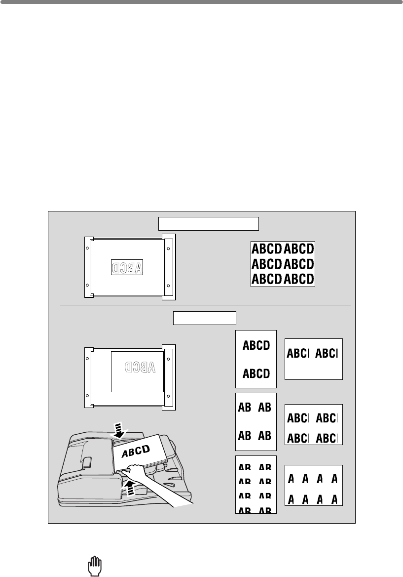
9-34
Repeating Automatically or Selecting Repeating Times
(Repeat: AUTO/ Repeat Mode)
Auto Detection mode will automatically set the equal repeat area to the size of the
original placed onto the platen glass by activating Non-image area erase. Repeat mode
will scan the image area specified by the selected paper size and mode (2 Repeat, 4
Repeat, or 8 Repeat), then arrange the image by specified times in one copy sheet.
>>>Auto Detection/ Repeat Mode Specifications<<<
❒Repeat Mode Magnification ratio: 1.00 (100 %) fixed
Mixed Original, Z-Folded Original, Sheet/Cover Insertion, Chapter, Combination, Booklet,
Layout, Full-Image Area, Reduce & Shift in Image Shift, Stamp/Overlay
❒Incompatible Conditions with Repeat Mode
APS, AMS, Rotation (if magnification is changed from 1.00), Group, Rotation Sort,
Rotation Group, Mixed Original, Z-Folded Original, Chapter, Combination, Booklet,
Memory
1. Touch APPLICATION on the Basic Screen.
Reminder!
press [AUTO RESET].
Auto Detection mode
Repeat mode
Copy
(2 Repeat)
Copy
(4 Repeat)
Copy
(8 Repeat)
Copy
❒Incompatible Conditions with Auto Detection Mode
Frame/Fold Erasure, AUTO Layout, Reduce & Shift in Image Shift, Overlay, Overlay
OHP Interleave, Image Insert, Dual Page, Non-Image Area Erase, Reverse Image,
OHP Interleave, Image Insert, Dual Page, Reverse Image, Frame/Fold Erasure, AUTO
❒Auto Detection Mode: Use the platen glass. RADF cannot be used.
When starting a new copying job, be sure to close the RADF securely, then
Using RADF, 2u2, 2u1, APS, AMS, Rotation, Group, Rotation Sort, Rotation Group,
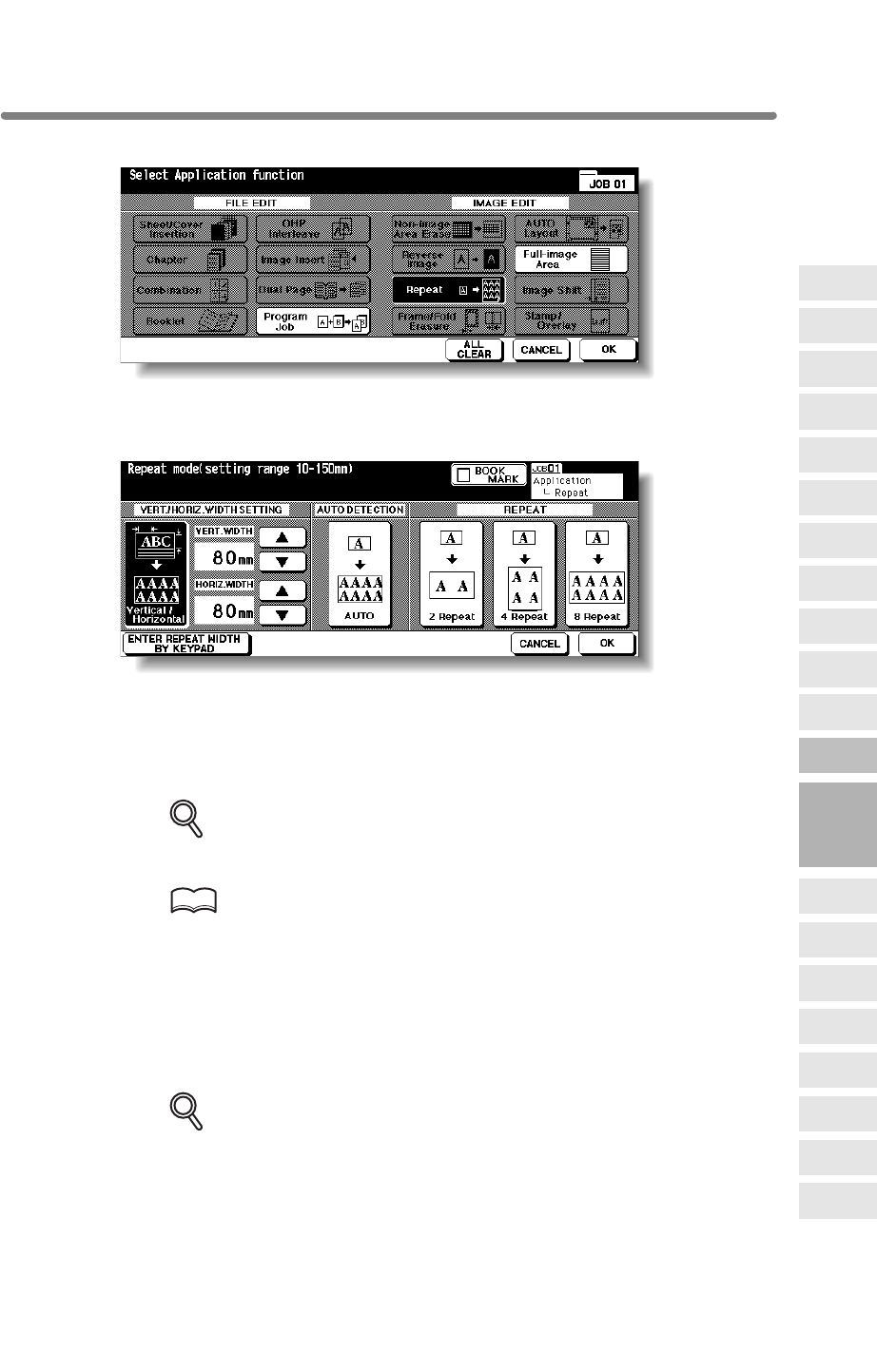
Repeating Automatically or Selecting Repeating Times (Repeat:
AUTO/ Repeat Mode) (continued)
9-35
2. Touch Repeat on the Application Selection Screen.
The Repeat Mode Selection Screen will be displayed.
3. Touch to highlight the desired mode key.
Touch AUTO to select the Auto Detection mode.
Touch 2 Repeat, 4 Repeat, or 8 Repeat to select the desired Repeat mode.
4. Touch OK.
The Application Selection Screen will be restored.
DETAILS
Non-Image Area Erase is automatically selected on the Application
Selection Screen when AUTO mode is selected.
HINT
When 2 Repeat mode is selected, Page space function of Image Shift can
be used to make the desired amount of blank space between the two
images on a page. See p. 9-44 to p. 9-46.
5. Touch OK on the Application Selection Screen.
The Basic Screen will be restored.
6. Select the desired magnification and paper size.
DETAILS
• APS and AMS are automatically released, and 1.00 (100%) is selected
as a magnification ratio.
• When 2 Repeat, 4 Repeat, or 8 Repeat is selected, the scanning area will
be a portion of the selected paper size equally divided according to the
selected mode.
In this case, magnification ratio will be fixed to 1.00 (100%).
•
Platen store mode will function automatically.
9
Applications
Reverse
Image
Non-Image
Area Erase
Program Job
Dual Page
Image Insert
OHP
Interleave
Booklet
Combination
Chapter
Sheet/Cover
Insertion
Application
Selection Screen
Repeat
Frame/Fold
Erasure
AUTO
Layout
Full-Image
Area
Image Shift
Reduce &
Shift
Stamp
Overlay
Overlay
Memory
Copy mode is automatically set to 1u1. When selecting 1u2 mode,
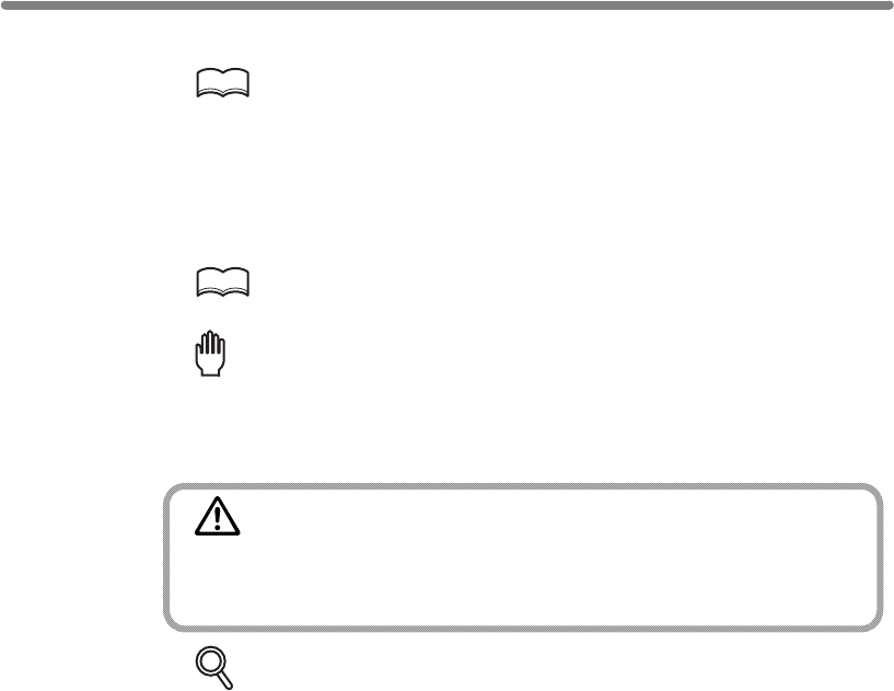
Repeating Automatically or Selecting Repeating Times (Repeat:
AUTO/ Repeat Mode) (continued)
9-36
7. Enter the desired print quantity from the control panel keypad.
HINT
See p. 3-7 for details on setting print quantity.
8. Position original.
For AUTO mode original, open the document feeder, then position the original FACE
DOWN on the platen glass.
HINT
See the illustration on p. 9-34 for details.
Reminder!
When AUTO mode is selected, Non-Image Area Erase functions automatically.
DO NOT close the document feeder.
9. Press [START].
CAUTION
When the finisher / trimmer unit / paper exit tray capacity is
exceeded due to the print quantity selected, remove the copied
sets as they exit; otherwise, mishandled paper will occur.
DETAILS
The AUTO mode may not operate properly if the lighting in the work place is
directly over the platen glass. In this case, consult your service representa-
tive about an appropriate place for installation.
For 2 Repeat, 4 Repeat or 8 Repeat mode original, RADF is also available.
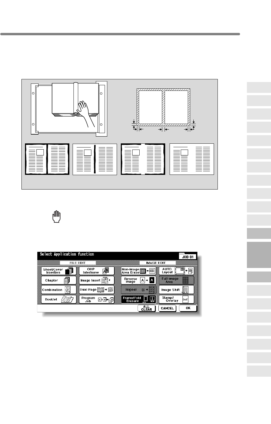
9-37
Eliminating Black Copy Marks Along Borders (Frame/Fold Erasure)
Use Frame/Fold Erasure to eliminate black copy marks along borders to clean up and
improve the presentation of the copy.
>>>Specifications for Frame/Fold Erasure<<<
❒Incompatible Conditions: Repeat, Full-Image Area
1. Touch APPLICATION on the Basic Screen.
Reminder!
press [AUTO RESET].
2. Touch Frame/Fold Erasure on the Application Selection Screen.
The Frame/Fold Erasure Selection Screen will be displayed.
Set original
General copying Frame Erasure
copying Fold Erasure
copying
Frame/Fold Erasure
copying
Fold
erasure
Frame
erasure
Frame
erasure
Frame
erasure
Frame
erasure
9
Applications
Reverse
Image
Non-Image
Area Erase
Program Job
Dual Page
Image Insert
OHP
Interleave
Booklet
Combination
Chapter
Sheet/Cover
Insertion
Application
Selection Screen
Repeat
Frame/Fold
Erasure
AUTO
Layout
Full-Image
Area
Image Shift
Reduce &
Shift
Stamp
Overlay
Overlay
Memory
When starting a new copying job, be sure to close the RADF securely, then
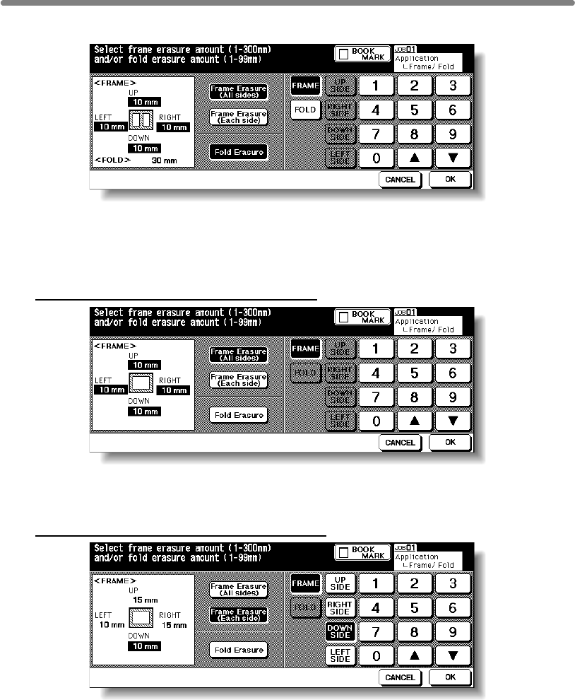
Eliminating Black Copy Marks Along Borders (Frame/Fold Erasure) (continued)
9-38
3. Touch to highlight the desired mode key.
Touch Frame Erasure (All sides), Frame Erasure (Each side), or Fold Erasure to
highlight it.
Either Frame erasure mode and Fold erasure can be selected in combination.
4. Specify the erasure amount in the selected mode.
To specify Frame Erasure (All sides) amount:
• Touch to highlight FRAME, if not highlighted, then use the touch screen keypad or
up/down arrow key to enter the desired erasure amount of the UP, DOWN, LEFT,
and RIGHT sides collectively, from 1 to 300mm in 1mm increments.
To specify Frame Erasure (Each side) amount:
• Touch to highlight FRAME, if not highlighted, then touch UP SIDE, RIGHT SIDE,
DOWN SIDE, or LEFT SIDE. The selected side amount will be highlighted in the left
illustration area of the screen.
Use the touch screen keypad or up/down arrow key to enter the desired erasure
amount, from 1 to 300mm in 1mm increments.
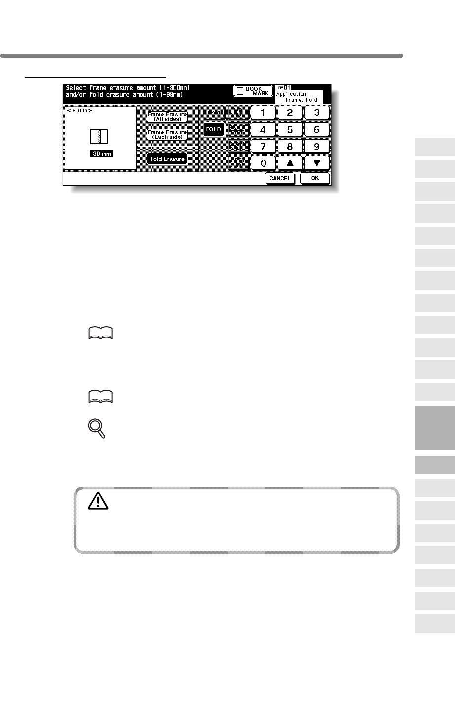
Eliminating Black Copy Marks Along Borders (Frame/Fold Erasure) (continued)
9-39
To specify Fold Erasure amount:
• Touch to highlight FOLD, if not highlighted, then use the touch screen keypad or up/
down arrow key to enter the desired erasure amount, from 1 to 99mm in 1mm
increments.
5. Touch OK.
The Application Selection Screen will be restored.
6. Touch OK on the Application Selection Screen.
The Basic Screen will be restored.
7. Enter the desired print quantity from the control panel keypad.
HINT
See p. 3-7 for details on setting print quantity.
8. Position original(s) FACE UP in the document feeder or FACE DOWN
on the platen glass.
HINT
For details on positioning originals, see p. 3-2 to p. 3-6.
DETAILS
When lowering the document feeder onto thick original (e.g. open book), do
not press it down too hard. Keep the document feeder open, if required.
9. Press [START].
CAUTION
When the finisher / trimmer unit / paper exit tray capacity is
exceeded due to the print quantity selected, remove the copied
sets as they exit; otherwise, mishandled paper will occur.
9
Applications
Reverse
Image
Non-Image
Area Erase
Program Job
Dual Page
Image Insert
OHP
Interleave
Booklet
Combination
Chapter
Sheet/Cover
Insertion
Application
Selection Screen
Repeat
Frame/Fold
Erasure
AUTO
Layout
Full-Image
Area
Image Shift
Reduce &
Shift
Stamp
Overlay
Overlay
Memory
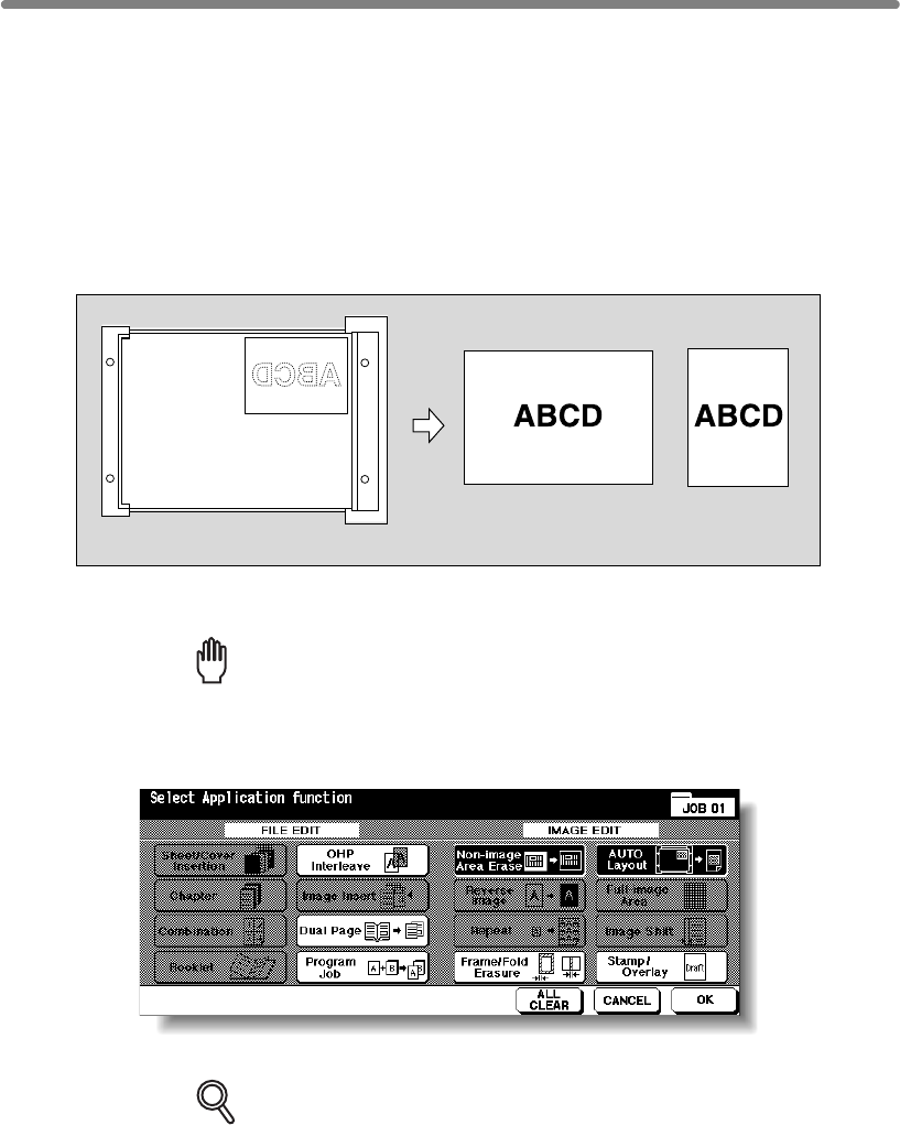
9-40
Copying Image in the Centre of Copy Paper (AUTO Layout)
Use this function to detect the image area of the original and centre the whole image on
the copy paper making it easy to copy small pieces of paper.
>>>Specifications for AUTO Layout<<<
❒Non-Image Area Erase is automatically selected. Release it manually when using
Group, Mixed Original, Z-Folded Original, Sheet/Cover Insertion, Chapter (available
when Non-Image Area Erase is released manually), Combination, Booklet, Image
Insert, Reverse Image, Repeat, Full-Image Area, Image Shift, Overlay, Storing
Image in Overlay Memory
1. Touch APPLICATION on the Basic Screen.
Reminder!
press [AUTO RESET].
2. Touch AUTO Layout on the Application Selection Screen.
The incompatible function keys will be dimmed to show inactivity.
DETAILS
•
to scan the original, touch to deselect this function.
When using the Dual Page with this function, the original smaller than the
selected paper size will be printed in the centre of the copy paper without
image division performed.
3. Touch OK on the Application Selection Screen.
The Basic Screen will be restored.
Auto Layout copying
Set original
•
RADF to scan originals.
When starting a new copying job, be sure to close the RADF securely, then
Non-Image Area Erase will be selected automatically. When using RADF
❒Incompatible Conditions: 2u2, 2u1, APS, AMS, Rotation, Rotation Sort, Rotation
Copying Image in the Centre of Copy Paper (AUTO Layout) (continued)
9-41
4. Select the desired magnification and paper size on the Basic Screen.
DETAILS
• APS and AMS are automatically released, and 1.00 (100%) is selected
as a magnification ratio.
•
Platen store mode will function automatically.
5. Enter the desired print quantity from the control panel keypad.
HINT
See p. 3-7 for details on setting print quantity.
6. Position original(s) FACE UP in the document feeder or FACE DOWN
on the platen glass.
HINT
For details on positioning originals, see p. 3-2 to p. 3-6.
Reminder!
7. Press [START].
CAUTION
When the finisher / trimmer unit / paper exit tray capacity is
exceeded due to the print quantity selected, remove the copied
sets as they exit; otherwise, mishandled paper will occur.
Having Any Problem?
The AUTO layout function may not operate properly if the lighting in the work
place is directly over the platen glass. In this case, consult your service rep-
resentative about an appropriate place for installation.
9
Applications
Reverse
Image
Non-Image
Area Erase
Program Job
Dual Page
Image Insert
OHP
Interleave
Booklet
Combination
Chapter
Sheet/Cover
Insertion
Application
Selection Screen
Repeat
Frame/Fold
Erasure
AUTO
Layout
Full-Image
Area
Image Shift
Reduce &
Shift
Stamp
Overlay
Overlay
Memory
original obliquely on the platen glass may cause black copy marks.
DO NOT close the RADF when Non-Image Area Erase is selected. Placing
Copy mode is automatically set to 1u1. When selecting 1u2 mode,
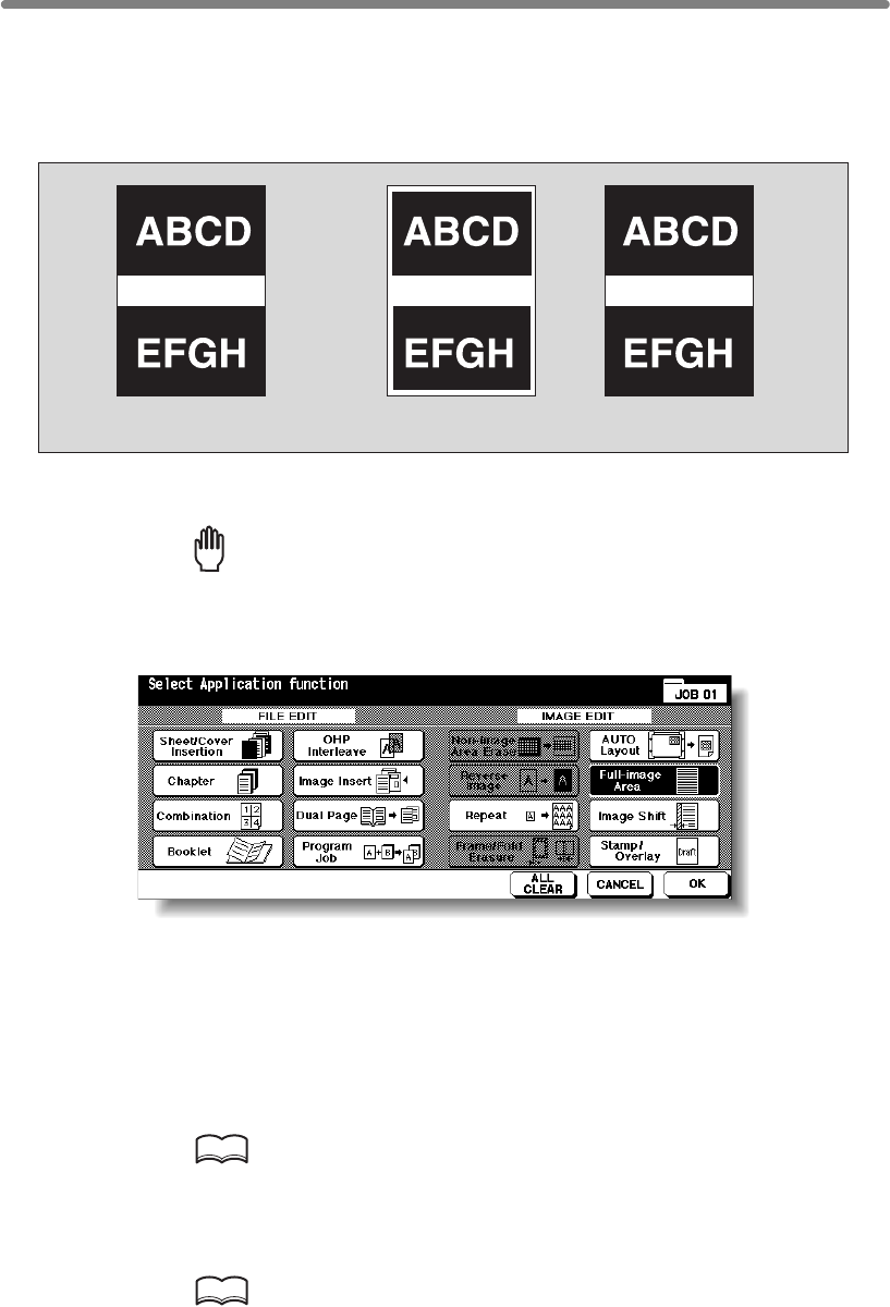
9-42
Printing Images Fully to the Edges (Full-Image Area)
Use this function to make copies printed completely to the edges.
>>>Specifications for Full-Image Area<<<
❒Incompatible Conditions: Rotation Sort, Rotation Group, Non-Image Area Erase,
Reverse Image, Frame/Fold Erasure
1. Touch APPLICATION on the Basic Screen.
Reminder!
press [AUTO RESET].
2.
Touch Full-image Area on the Application Selection Screen.
The incompatible function keys will be dimmed to show inactivity.
3. Touch OK on the Application Selection Screen.
The Basic Screen will be restored.
4. Select additional copy conditions, as desired.
5. Enter the desired print quantity from the control panel keypad.
HINT
See p. 3-7 for details on setting print quantity.
6. Position original(s) FACE UP in the document feeder or FACE DOWN
on the platen glass.
HINTS
For details on positioning originals, see p. 3-2 to p. 3-6.
Original Normal copy Full-Image Area copy
When starting a new copying job, be sure to close the RADF securely, then

Printing Images Fully to the Edges (Full-Image Area) (continued)
9-43
7. Press [START].
CAUTION
When the finisher / trimmer unit / paper exit tray capacity is
exceeded due to the print quantity selected, remove the copied
sets as they exit; otherwise, mishandled paper will occur.
9
Applications
Reverse
Image
Non-Image
Area Erase
Program Job
Dual Page
Image Insert
OHP
Interleave
Booklet
Combination
Chapter
Sheet/Cover
Insertion
Application
Selection Screen
Repeat
Frame/Fold
Erasure
AUTO
Layout
Full-Image
Area
Image Shift
Reduce &
Shift
Stamp
Overlay
Overlay
Memory
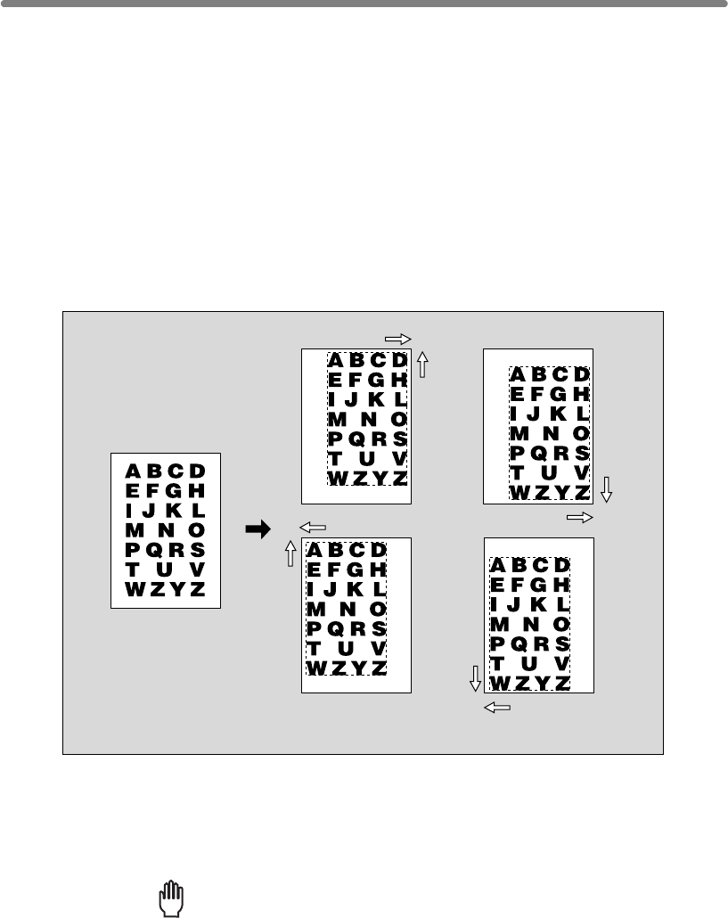
9-44
Adjusting Position of Copy Image (Image Shift)
Use Image Shift to adjust the position of copy images, e.g. for the purpose of creating a
new binding margin on originals to make it easier for filing purposes.
Page Space function is available only when Booklet or 2 Repeat mode of Repeat has
been already selected. Use this function to make the desired amount of blank space
between the two images on a page. See the illustration on p. 9-46 for details.
If image loss is likely, select the Reduce & Shift mode instead of regular Image shift.
See p. 9-47.
>>>Specifications for Image Shift<<<
❒Shift amount: 0 to 250mm in 1mm increments
Setting in 0.1mm increments using up/down arrow key is also available by Key
Operator setting. See p. 13-39 to 13-44.
❒Incompatible Conditions: AUTO Layout, Storing images in Overlay Memory
1. Select the copy mode and paper size from the Basic Screen, as
required.
2. Touch APPLICATION on the Basic Screen.
Reminder!
press [AUTO RESET].
Original
Copies
Up
Up
Down
Down
Left
Left
Right
Right
When starting a new copying job, be sure to close the RADF securely, then
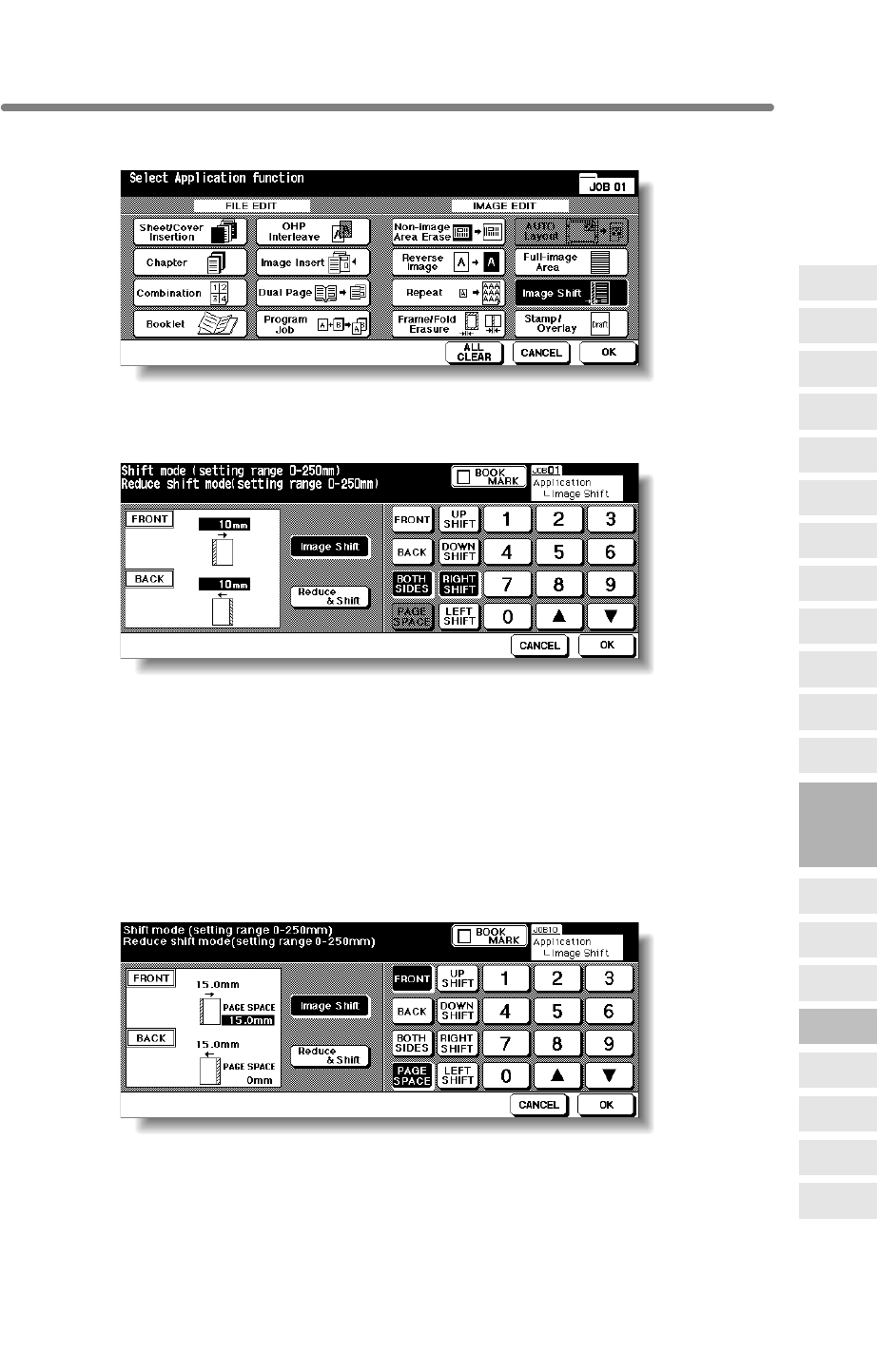
Adjusting Position of Copy Image (Image Shift) (continued)
9-45
3.
Touch Image Shift on the Application Selection Screen.
4. Touch Image Shift on the Image Shift Setting Screen, then specify the
shift direction and amount.
Touch FRONT or BACK to specify the shift direction and amount individually; or touch
BOTH SIDES to specify collectively. The BACK and BOTH SIDES keys function only
for duplex copying.
Touch to highlight the desired shift direction key, then use the touch screen keypad or
up/down arrow key to enter the desired shift amount, from 0 to 250mm in 1mm
increments.
The image display on the screen allows you to view the shift direction and amount to
be created on the printed sheets.
When Booklet or 2 Repeat mode of Repeat has been already selected, the PAGE
SPACE key appears clear on the screen to show its availability.
If desired, touch PAGE SPACE to highlight it, then enter the desired amount using the
touch screen keypad or up/down arrow key.
5. Touch OK.
The Application Selection Screen will be restored.
9
Applications
Reverse
Image
Non-Image
Area Erase
Program Job
Dual Page
Image Insert
OHP
Interleave
Booklet
Combination
Chapter
Sheet/Cover
Insertion
Application
Selection Screen
Repeat
Frame/Fold
Erasure
AUTO
Layout
Full-Image
Area
Image Shift
Reduce &
Shift
Stamp
Overlay
Overlay
Memory
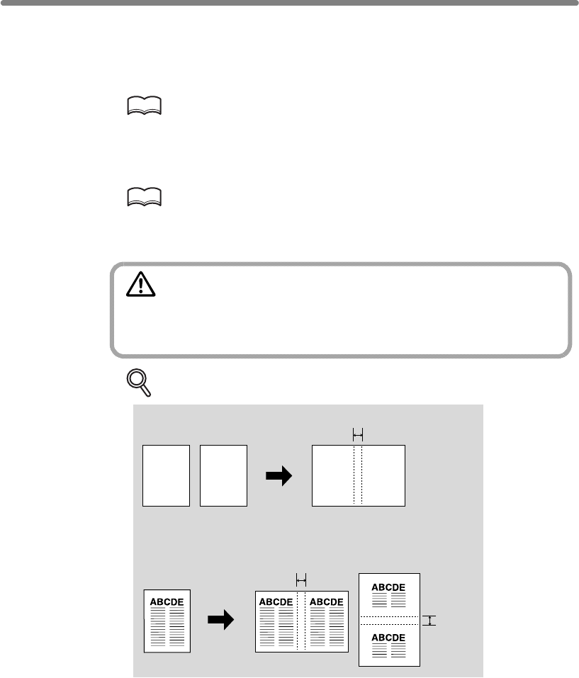
Adjusting Position of Copy Image (Image Shift) (continued)
9-46
6. Touch OK on the Application Selection Screen.
The Basic Screen will be restored.
7. Enter the desired print quantity from the control panel keypad.
HINT
See p. 3-7 for details on setting print quantity.
8. Position original(s) FACE UP in the document feeder or FACE DOWN
on the platen glass.
HINT
For details on positioning originals, see p. 3-2 to p. 3-6.
9. Press [START].
CAUTION
When the finisher / trimmer unit / paper exit tray capacity is
exceeded due to the print quantity selected, remove the copied
sets as they exit; otherwise, mishandled paper will occur.
DETAILS: Page Space Function
Original
Original
Page space
Booklet
2 Repeat in Repeat
AB AB
Page space
Page space
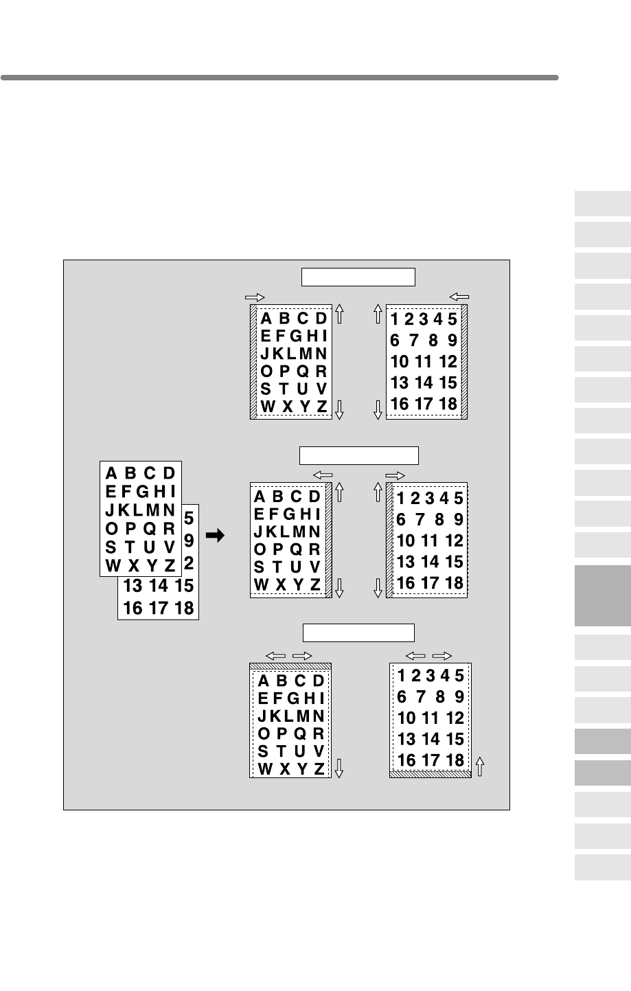
9-47
Reducing Images to Create Binding Margin (Reduce&Shift)
Use Reduce & Shift instead of regular Image Shift to prevent image loss when creating
a binding margin.
>>>Specifications for Reduce & Shift<<<
❒AMS is automatically selected and cannot be released.
❒Shift amount: 0 to 250mm in 1mm increments
Setting in 0.1mm increments using up/down arrow key is also available by Key
Operator setting. See p. 13-39 to 13-44.
❒Incompatible Conditions: Change magnification, V/H zoom, APS, Mixed Original,
Dual Page, Non-Image Area Erase, Repeat, AUTO Layout, Overlay, Storing Image
in Overlay Memory
Originals
Right
Front Back
Up
Down
Left
Right
Left
Down
Right
Left
Up
Left binding margin
Right
Front
Front
Back
Back
Front Back
Up
Down
Left
Right binding margin
Top binding margin
9
Applications
Reverse
Image
Non-Image
Area Erase
Program Job
Dual Page
Image Insert
OHP
Interleave
Booklet
Combination
Chapter
Sheet/Cover
Insertion
Application
Selection Screen
Repeat
Frame/Fold
Erasure
AUTO
Layout
Full-Image
Area
Image Shift
Reduce &
Shift
Stamp
Overlay
Overlay
Memory
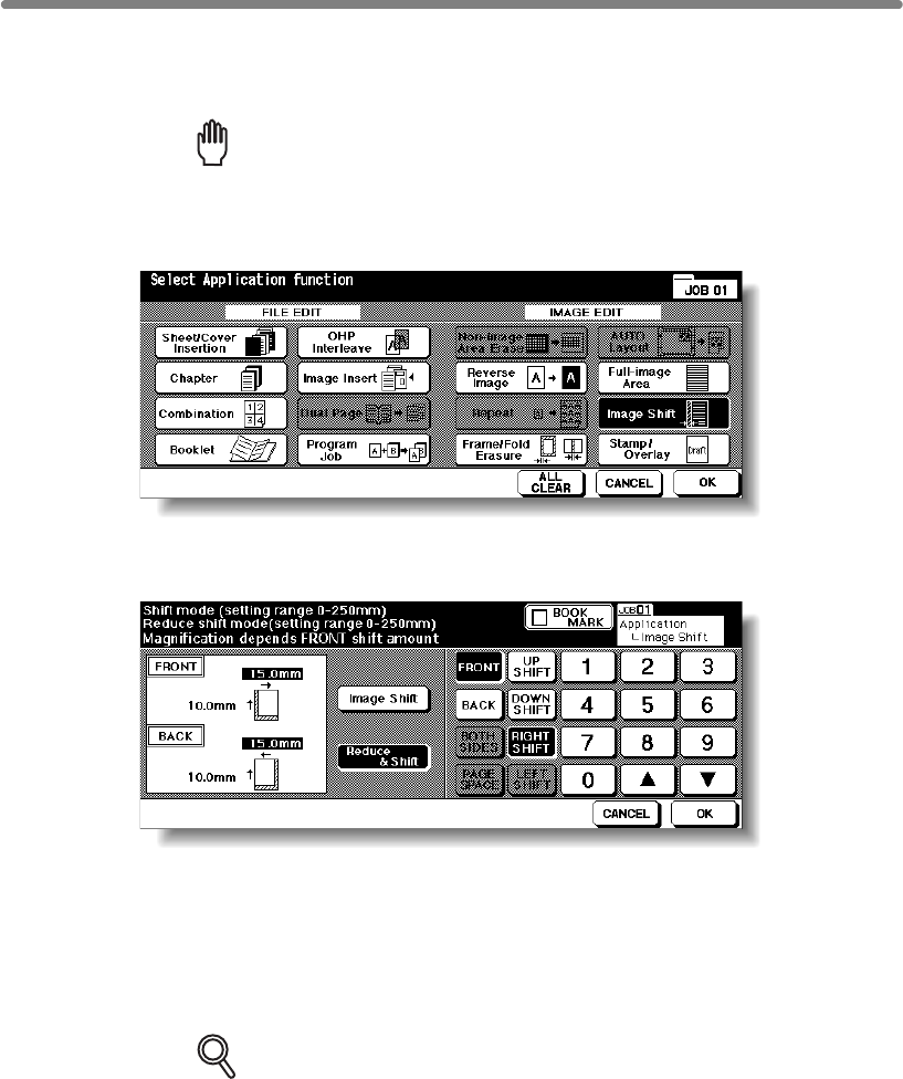
Reducing Images to Create Binding Margin (Reduce&Shift) (continued)
9-48
1. Select the copy mode and paper size, as required.
2. Touch APPLICATION on the Basic Screen.
Reminder!
press [AUTO RESET].
3.
Touch Image Shift on the Application Selection Screen.
4. Touch Reduce & Shift on the Image Shift Setting Screen, then specify
the shift direction and amount.
Touch FRONT or BACK. In Reduce & Shift mode, the BOTH SIDES key appears
dimmed to show inactivity.
Touch to highlight the desired shift direction key, then use the touch screen keypad or
up/down arrow key to enter the desired shift amount, from 0 to 250mm in 1mm
increments.
The image display on the screen allows you to view the shift direction and amount to
be printed on the printed sheets.
DETAILS
The AMS will automatically determine the magnification ratio according to
the shift amount specified for the front page. The shift amount and
magnification ratio determined for the front page will be automatically
applied to the back page. If any positioning adjustment is required, touch
BACK and make direction and amount change.
5. Touch OK.
The Application Selection Screen will be restored.
6. Touch OK on the Application Selection Screen.
The Basic Screen will be restored.
When starting a new copying job, be sure to close the RADF securely, then

Reducing Images to Create Binding Margin (Reduce&Shift) (continued)
9-49
7. Enter the desired print quantity from the control panel keypad.
HINT
See p. 3-7 for details on setting print quantity.
8. Position original(s) FACE UP in the document feeder or FACE DOWN
on the platen glass.
HINT
For details on positioning originals, see p. 3-2 to p. 3-6.
9. Press [START].
CAUTION
When the finisher / trimmer unit / paper exit tray capacity is
exceeded due to the print quantity selected, remove the copied
sets as they exit; otherwise, mishandled paper will occur.
9
Applications
Reverse
Image
Non-Image
Area Erase
Program Job
Dual Page
Image Insert
OHP
Interleave
Booklet
Combination
Chapter
Sheet/Cover
Insertion
Application
Selection Screen
Repeat
Frame/Fold
Erasure
AUTO
Layout
Full-Image
Area
Image Shift
Reduce &
Shift
Stamp
Overlay
Overlay
Memory
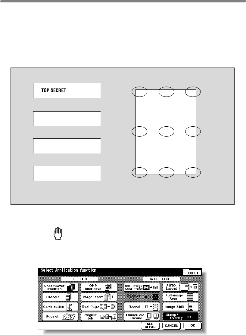
9-50
Printing Stamp, Page, Date/Time onto Copies (Stamp)
This function allows you to print onto output copies the desired type of stamp, page
number, numbering, and date/time at the location designated on the screen.
The four stamp types and watermark (described in the next subsection) provided on the
Stamp/Overlay Selection Screen can be used individually or in multiple combinations.
>>>Specification for STAMP, SET NUMBERING, PAGE NUMBERING, DATE/TIME<<<
❒Incompatible Conditions: Reverse Image, Repeat except 2/4/8 Repeat, Overlay
(with STAMP and SET NUMBERING), Overlay Memory
1. Touch APPLICATION on the Basic Screen.
Reminder!
press [AUTO RESET].
2. Touch Stamp/Overlay on the Application Selection Screen.
The Stamp/Overlay Selection Screen will be displayed.
Printing positions
Top-Left T-Middle T-Right
Lower-Left L-Middle L-Right
Middle-Left Middle M-Right
DATE/TIME
’02/10/10 10:30AM
PAGE NUMBERING
2 / 5
SET NUMBERING
002 / 005
STAMP
When starting a new copying job, be sure to close the RADF securely, then
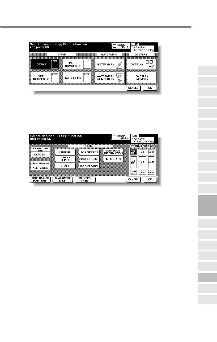
Printing Stamp, Page, Date/Time onto Copies (Stamp) (continued)
9-51
3. Touch to select the desired key in the STAMP area.
The subsequent screen will be displayed to allow you to specify the selected stamp
type.
4. When selecting STAMP: Specify the stamp type, printing position,
character size and printed page.
Touch to highlight the desired stamp key and printing position key on the screen. If fine
adjustment is required, touch FINE ADJ. OF POSITION to display the Fine Adjustment
Setting Screen. See p. 9-54 for details.
Touch CHARACTER SIZE to select LARGER or SMALLER.
Touch PRINTED PAGE to designate whether to print the selected stamp on the cover
only or on all pages.
9
Applications
Reverse
Image
Non-Image
Area Erase
Program Job
Dual Page
Image Insert
OHP
Interleave
Booklet
Combination
Chapter
Sheet/Cover
Insertion
Application
Selection Screen
Repeat
Frame/Fold
Erasure
AUTO
Layout
Full-Image
Area
Image Shift
Reduce &
Shift
Stamp
Overlay
Overlay
Memory
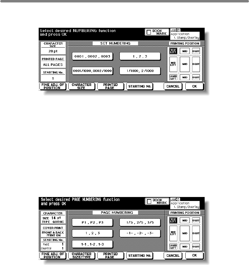
Printing Stamp, Page, Date/Time onto Copies (Stamp) (continued)
9-52
When selecting SET NUMBERING: Specify the numbering type,
printing position, character size, printed page and starting No.
Touch to highlight the desired numbering type key and printing position key on the
screen. If fine adjustment is required, touch FINE ADJ. OF POSITION to display the
Fine Adjustment Setting Screen. See p. 9-54 for details.
Touch CHARACTER SIZE to select 20pt or 36pt.
Touch PRINTED PAGE to designate whether to print the selected stamp on the cover
only or on all pages.
Touch STARTING No. to designate the starting number, if required. See p. 9-54 for
details.
When selecting PAGE NUMBERING: Specify the page numbering
type, printing position, character size, printed page and starting No.
Touch to highlight the desired page numbering type key and printing position key on
the screen. If fine adjustment is required, touch FINE ADJ. OF POSITION to display
the Fine Adjustment Setting Screen. See p. 9-54 for details.
Touch CHARACTER SIZE/TYPE to select the character size (8pt, 10pt, 12pt or 14pt)
and type (GOTHIC or MING). See p. 9-55 for details.
Touch PRINTED PAGE to designate whether to print the selected stamp on the front/
back cover or insertions. See p. 9-55 for details.
Touch STARTING No. to designate the starting number, if required. See p. 9-54 for
details.
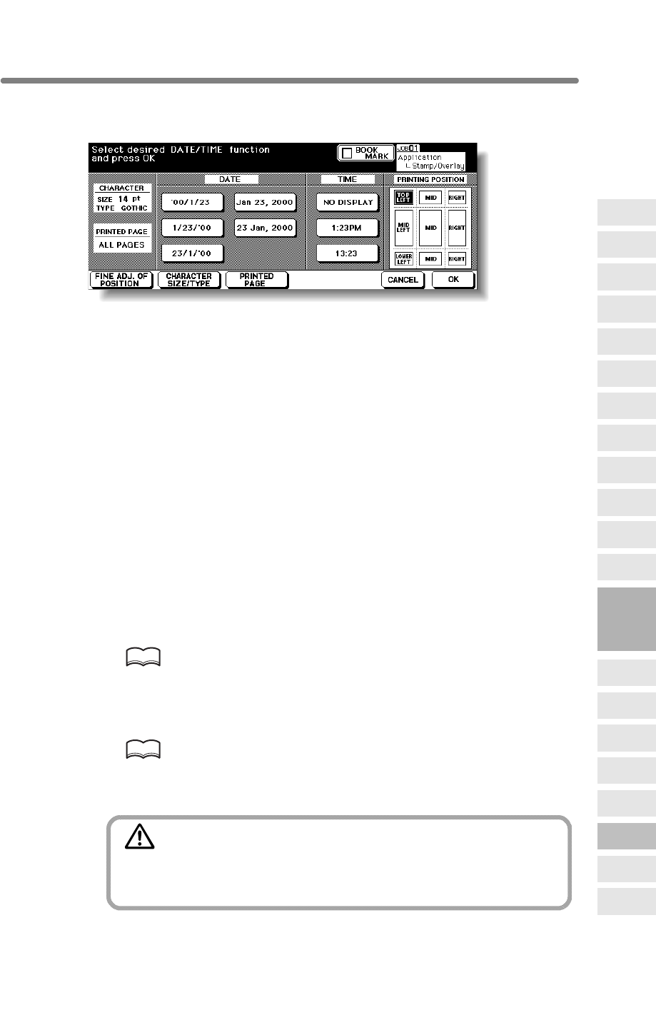
Printing Stamp, Page, Date/Time onto Copies (Stamp) (continued)
9-53
When selecting DATE/TIME: Specify the date/time type, printing
position, character size and printed page.
Touch to highlight the desired date, time, and printing position keys on the screen. If
fine adjustment is required, touch FINE ADJ. OF POSITION to display the Fine
Adjustment Setting Screen. See p. 9-54 for details.
Touch CHARACTER SIZE/TYPE to select the character size (8pt, 10pt, 12pt or 14pt)
and type (GOTHIC or MING). See p. 9-55 for details.
Touch PRINTED PAGE to designate whether to print the selected stamp on the cover
only or on all pages.
5. Touch OK.
The Stamp/Overlay Selection Screen will be restored.
Touch to select another stamp function key to use in combination, if desired.
6. Touch OK on the Stamp/Overlay Selection Screen.
The Application Selection Screen will be restored.
7. Touch OK on the Application Selection Screen.
The Basic Screen will be restored.
8. Enter the desired print quantity from the control panel keypad.
HINT
See p. 3-7 for details on setting print quantity.
9. Position original(s) FACE UP in the document feeder or FACE DOWN
on the platen glass.
HINT
For details on positioning originals, see p. 3-2 to p. 3-6.
10. Press [START].
CAUTION
When the finisher / trimmer unit / paper exit tray capacity is
exceeded due to the print quantity selected, remove the copied
sets as they exit; otherwise, mishandled paper will occur.
9
Applications
Reverse
Image
Non-Image
Area Erase
Program Job
Dual Page
Image Insert
OHP
Interleave
Booklet
Combination
Chapter
Sheet/Cover
Insertion
Application
Selection Screen
Repeat
Frame/Fold
Erasure
AUTO
Layout
Full-Image
Area
Image Shift
Reduce &
Shift
Stamp
Overlay
Overlay
Memory
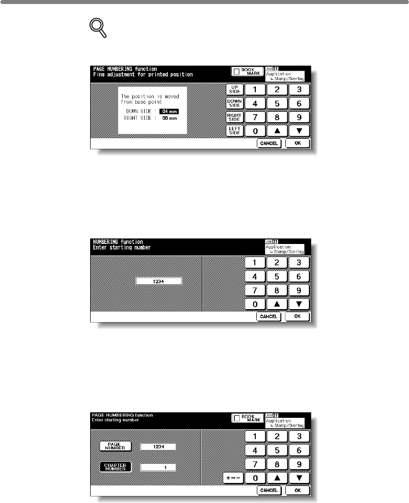
Printing Stamp, Page, Date/Time onto Copies (Stamp) (continued)
9-54
DETAILS: Fine Adjustment Setting Screen
When FINE ADJ. OF POSITION is touched, the Fine Adjustment Setting
Screen will be displayed.
Touch
UP SIDE
,
DOWN SIDE
,
RIGHT SIDE
, or
LEFT SIDE
to specify the
direction, then use the touch screen keypad or up/down arrow key to enter the
desired amount, from 0 to 50mm. Touch
OK
to return to the previous screen.
Starting No. Setting Screen: Available from SET NUMBERING or WATERMARK
NUMBERING
Use the touch screen keypad or up/down arrow key to enter the desired
starting number, then touch OK to return to the previous screen.
Starting No. Setting Screen: Available from PAGE NUMBERING
When Chapter is already selected, the chapter starting number can also be
specified on the Starting No. Setting Screen.
Touch PAGE NUMBER or CHAPTER NUMBER to highlight it, then use the
touch screen keypad or up/down arrow key to enter the desired starting
number for each.
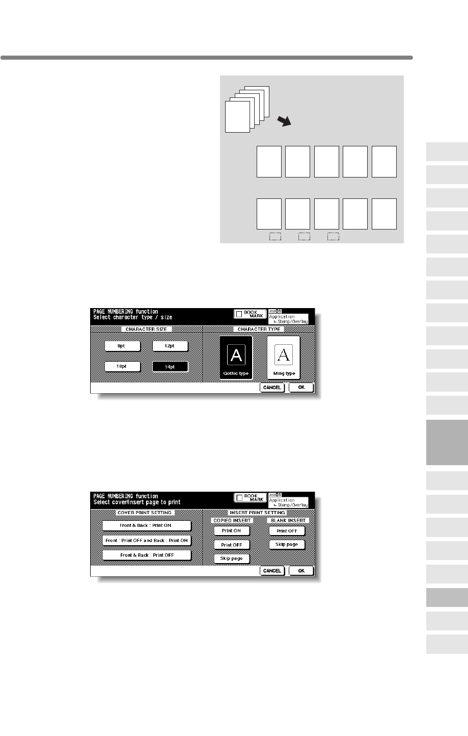
Printing Stamp, Page, Date/Time onto Copies (Stamp) (continued)
9-55
Use +– to enter a minus
number to print from
halfway through, e.g. –2 to
print “1” from page 4.
Touch OK to return to the
previous screen.
Character Size/Type Selection Screen: from PAGE NUMBERING or DATE/TIME
When CHARACTER SIZE/TYPE is touched, the Character Size/Type
Selection Screen will be displayed.
Touch to select the desired key, then touch OK to return to the previous
screen.
Cover/Insert Print Setting Selection Screen: from PAGE NUMBERING
When copied/blank insertion mode of Sheet/Cover Insertion has been
already selected, this screen allows you to specify whether to print the page
number on insertions, or skip them from the page count.
Touch to select the desired key, then touch OK to return to the Page
Numbering Type Selection Screen.
Originals
Copies
Copies
56234
12
–2 –1 0
When “(+)2” is entered:
When “–2” is entered:
9
Applications
Reverse
Image
Non-Image
Area Erase
Program Job
Dual Page
Image Insert
OHP
Interleave
Booklet
Combination
Chapter
Sheet/Cover
Insertion
Application
Selection Screen
Repeat
Frame/Fold
Erasure
AUTO
Layout
Full-Image
Area
Image Shift
Reduce &
Shift
Stamp
Overlay
Overlay
Memory
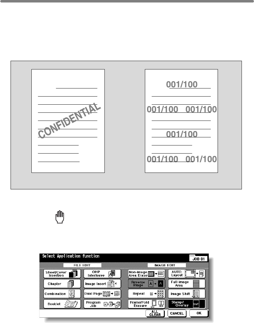
9-56
Printing Watermark onto Copies (Stamp)
Use this function to print the desired letter type obliquely in the centre of the page
(WATERMARK), or the numbers in the specified form repeatedly over the scanned
image (WATERMARK NUMBERING).
>>>Specification for WATERMARK and WATERMARK NUMBERING<<<
❒Incompatible Conditions: Reverse Image, Repeat except 2/4/8 Repeat, Overlay,
Overlay Memory
1. Touch APPLICATION on the Basic Screen.
Reminder!
press [AUTO RESET].
2. Touch Stamp/Overlay on the Application Selection Screen.
The Stamp/Overlay Selection Screen will be displayed.
WATERMARK WATERMARK NUMBERING
A
Z
A
Z
When starting a new copying job, be sure to close the RADF securely, then
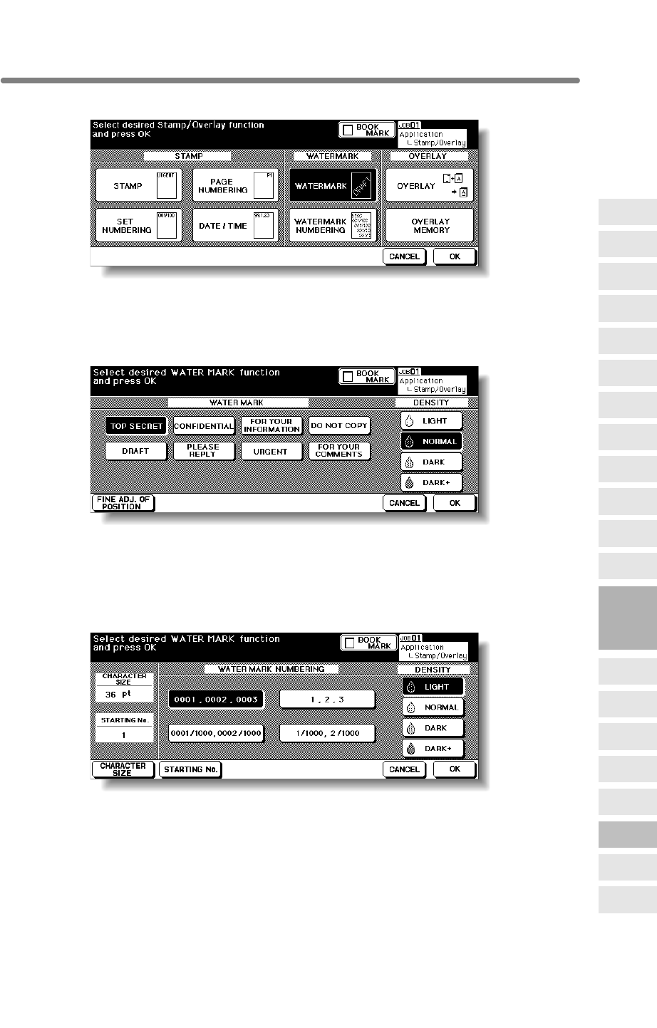
Printing Watermark onto Copies (Stamp) (continued)
9-57
3. Touch WATERMARK or WATERMARK NUMBERING, as desired.
The subsequent screen will be displayed to allow you to specify the selected
watermark type.
4. When selecting WATERMARK: Specify the desired watermark type
and density.
Touch to highlight the desired watermark key and density key on the screen. If fine
adjustment of the centred watermark position is required, touch FINE ADJ. OF POSI-
TION to display the Fine Adjustment Setting Screen. See p. 9-54 for details.
When selecting WATERMARK NUMBERING: Specify the desired
watermark numbering type, density, character size and starting No.
Touch to highlight the desired watermark key and density key on the screen.
Touch CHARACTER SIZE to select 20pt or 36pt.
Touch STARTING No. to designate the starting number, if required. See p. 9-54 for
details.
5. Touch OK.
The Stamp/Overlay Selection Screen will be restored.
Touch to select another stamp function key to use in combination, if desired.
9
Applications
Reverse
Image
Non-Image
Area Erase
Program Job
Dual Page
Image Insert
OHP
Interleave
Booklet
Combination
Chapter
Sheet/Cover
Insertion
Application
Selection Screen
Repeat
Frame/Fold
Erasure
AUTO
Layout
Full-Image
Area
Image Shift
Reduce &
Shift
Stamp
Overlay
Overlay
Memory
Printing Watermark onto Copies (Stamp) (continued)
9-58
6. Touch OK on the Stamp/Overlay Selection Screen.
The Application Selection Screen will be restored.
7. Touch OK on the Application Selection Screen.
The Basic Screen will be restored.
8. Enter the desired print quantity from the control panel keypad.
HINT
See p. 3-7 for details on setting print quantity.
9. Position original(s) FACE UP in the document feeder or FACE DOWN
on the platen glass.
HINT
For details on positioning originals, see p. 3-2 to p. 3-6.
10. Press [START].
CAUTION
When the finisher / trimmer unit / paper exit tray capacity is
exceeded due to the print quantity selected, remove the copied
sets as they exit; otherwise, mishandled paper will occur.
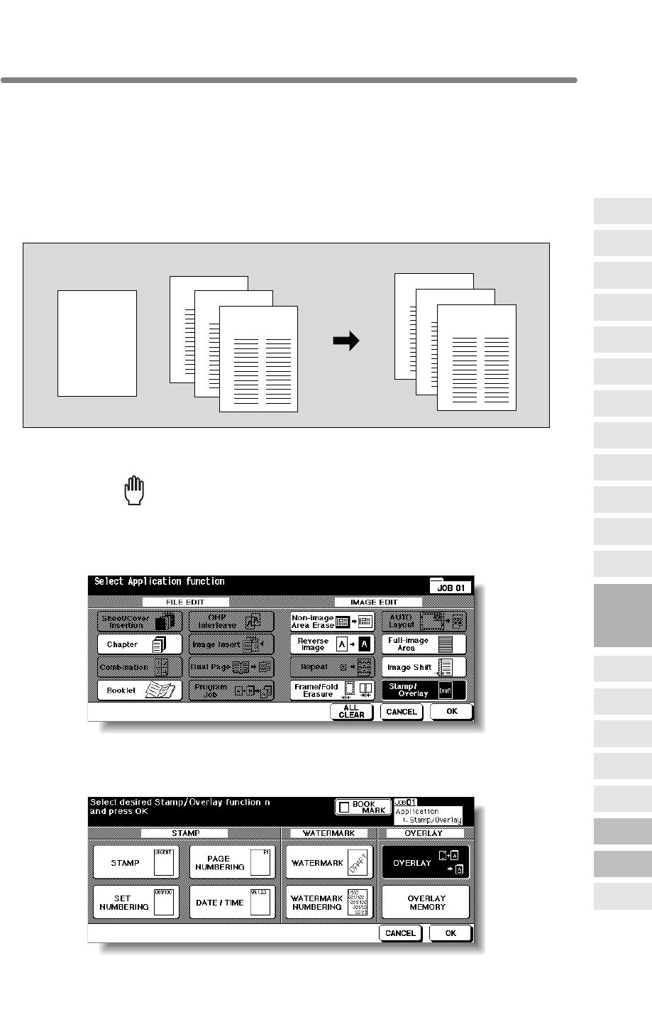
9-59
Overlaying an Image onto Each Page Copied in the Job (Overlay)
Use this function to scan an image, then overlay the image onto each page copied in
the job.
>>>Specification for Overlay<<<
❒Store mode is automatically selected.
❒Incompatible Conditions: Rotation, Rotation Sort, Rotation Group, Mixed Original,
Sheet/Cover Insertion, Combination, OHP Interleave, Image Insert, Dual page, Pro-
gram Job, Repeat, AUTO Layout, Reduce & Shift in Image Shift, STAMP, SET NUM-
BERING, WATERMARK, WATERMARK NUMBERING
1. Touch APPLICATION on the Basic Screen.
Reminder!
press [AUTO RESET].
2. Touch Stamp/Overlay on the Application Selection Screen.
The Stamp/Overlay Selection Screen will be displayed.
3. Touch OVERLAY.
1st scanned original Originals scanned
2nd and later
Copies in Overlay mode
ABCD
ABCD
ABCD
ABCD
9
Applications
Reverse
Image
Non-Image
Area Erase
Program Job
Dual Page
Image Insert
OHP
Interleave
Booklet
Combination
Chapter
Sheet/Cover
Insertion
Application
Selection Screen
Repeat
Frame/Fold
Erasure
AUTO
Layout
Full-Image
Area
Image Shift
Reduce &
Shift
Stamp
Overlay
Overlay
Memory
When starting a new copying job, be sure to close the RADF securely, then

Overlaying an Image onto Each Page Copied in the Job (Overlay) (continued)
9-60
4. Touch OK on the Stamp/Overlay Selection Screen.
The Application Selection Screen will be restored.
5. Touch OK on the Application Selection Screen.
The Basic Screen will be restored.
The Store mode is automatically selected.
6. Select the desired paper size and magnification on the Basic Screen.
APS and AMS are automatically released, and 1.00 (100%) is selected as a
magnification ratio.
7. Enter the desired print quantity from the control panel keypad.
HINT
See p. 3-7 for details on setting print quantity.
8. Position the overlaying original.
Position the original FACE UP in the document feeder or FACE DOWN on the platen
glass.
HINT
For details on positioning originals, see p. 3-2 to p. 3-6.
9. Press [START] to scan.
The original image will be scanned into memory.
10. Position the original(s) to be overlaid.
Position the original FACE UP in the document feeder or FACE DOWN on the platen
glass.
11. Press [START] to scan.
12. Repeat steps 10 and 11 for all originals.
13. Touch STORE to exit the Store mode, then press [START] to print.
CAUTION
When the finisher / trimmer unit / paper exit tray capacity is
exceeded due to the print quantity selected, remove the copied
sets as they exit; otherwise, mishandled paper will occur.
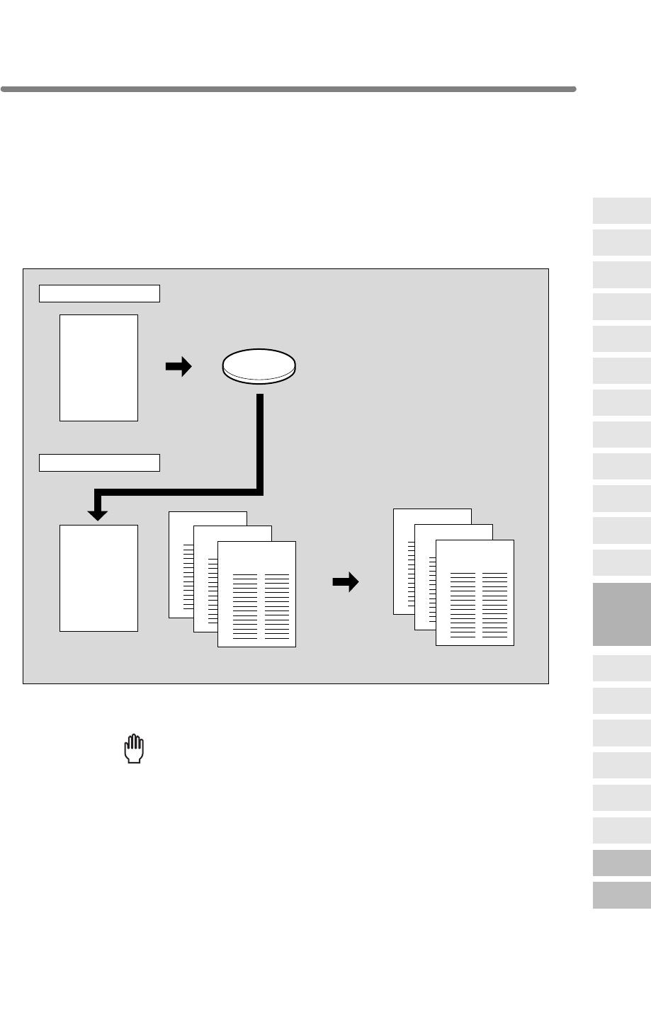
9-61
Storing an Overlay Image in HDD / Overlaying Image
Stored in HDD (Overlay Memory)
Use Overlay Memory to scan and store several images in HDD, then recall the desired
image from the HDD to overlay onto each page copied in the job.
>>>Specification for Overlay Memory<<<
Rotation, Reserve Mode, Interrupt Mode, Selecting Output Mode, Mixed Original, Z-
OHP Interleave, Image Insert, Dual Page, Program Job, Non-Image Area Erase,
Reverse Image, Repeat, AUTO Layout, Image Shift, Stamp, Overlay
❒Incompatible Conditions with Output: Reverse Image, STAMP, SET NUMBERING,
WATERMARK, WATERMARK NUMBERING in Stamp
1. Touch APPLICATION on the Basic Screen.
Reminder!
press [AUTO RESET].
Recalled image
Overlaying image
Store in HDD
Output
Recall overlaying image
Overlay originals Copies in Overlay Memory mode
Image Store
Output
ABCD
ABCD
HDD
ABCD
ABCD
ABCD
9
Applications
Reverse
Image
Non-Image
Area Erase
Program Job
Dual Page
Image Insert
OHP
Interleave
Booklet
Combination
Chapter
Sheet/Cover
Insertion
Application
Selection Screen
Repeat
Frame/Fold
Erasure
AUTO
Layout
Full-Image
Area
Image Shift
Reduce &
Shift
Stamp
Overlay
Overlay
Memory
Folded Original, Tab Paper, Sheet/Cover Insertion, Chapter, Combination, Booklet,
When starting a new copying job, be sure to close the RADF securely, then
❒Incompatible Conditions with Image Store: Using RADF, 1u2, 2u2, 2u1, AMS,
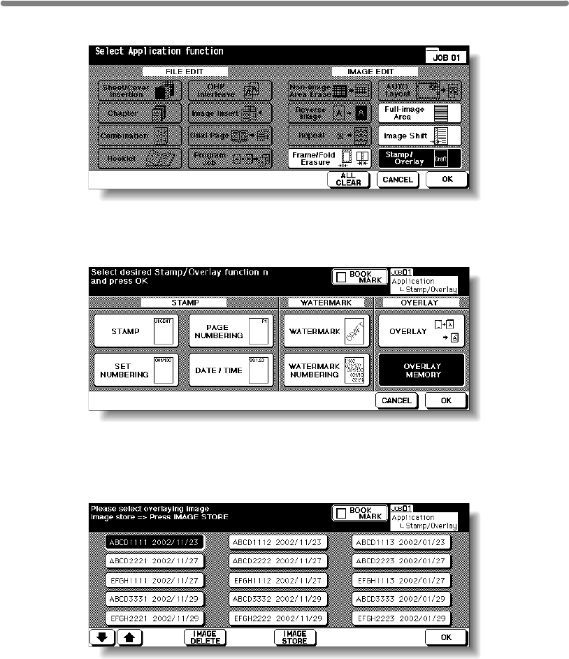
Storing an Overlay Image in HDD / Overlaying Image Stored in
HDD (Overlay Memory) (continued)
9-62
2. Touch Stamp/Overlay on the Application Selection Screen.
The Stamp/Overlay Selection Screen will be displayed.
3. Touch OVERLAY MEMORY.
The Overlaying Image Selection Screen will be displayed.
Proceed to step 9, when recalling only the stored image.
4. Touch IMAGE STORE to display the Image Name Entry Screen.
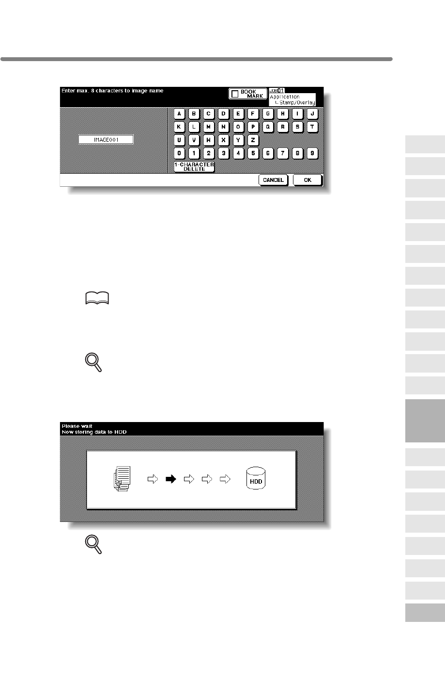
Storing an Overlay Image in HDD / Overlaying Image Stored in
HDD (Overlay Memory) (continued)
9-63
5. Enter the desired image name.
Use the touch screen keypad to enter the desired name up to 8 characters. The date
when you made this entry will be stored automatically.
To correct an entry, touch 1-CHARACTER DELETE repeatedly to delete each
character, then enter the correct name.
6. If the image name is correct, touch OK.
The Basic Screen to store the overlaying image will be displayed.
Select the desired copy conditions.
HINT
The popup menu may be displayed to prompt you that the entered image
name has been already used. See p. 9-65 for details.
7. Position the overlaying original on the platen glass.
DETAILS
The document feeder cannot be used for storing the overlaying image.
8. Press [START] to scan.
The Overlaying Image Data Storing Screen will be displayed.
DETAILS
To stop scanning, press [STOP].
The machine automatically starts to store the overlaying image data in the HDD. The
Overlaying Image Selection Screen will resume when the storing function is
completed.
To continue to store the overlaying image data, return to step 4.
9
Applications
Reverse
Image
Non-Image
Area Erase
Program Job
Dual Page
Image Insert
OHP
Interleave
Booklet
Combination
Chapter
Sheet/Cover
Insertion
Application
Selection Screen
Repeat
Frame/Fold
Erasure
AUTO
Layout
Full-Image
Area
Image Shift
Reduce &
Shift
Stamp
Overlay
Overlay
Memory
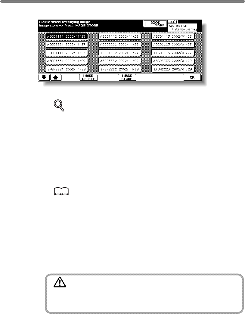
Storing an Overlay Image in HDD / Overlaying Image Stored in
HDD (Overlay Memory) (continued)
9-64
9. Touch to select the desired overlaying image data, then touch OK.
The Stamp/Overlay Selection Screen will be restored.
DETAILS: Image Delete Key on the Overlay Image Selection Screen
If the IMAGE DELETE key is displayed on the Overlay Image Selection
Screen, you can delete the stored image and name. Select the image name
using up/down arrow key to scroll, then touch IMAGE DELETE.
10. Touch OK to return to the Application Selection Screen.
11. Touch OK to return to the Basic Screen.
The Store mode is automatically selected, and APS and AMS are released.
Set the desired conditions on the Basic Screen.
12. Enter the desired print quantity from the control panel keypad.
HINT
See p. 3-7 for details on setting print quantity.
13. Position the original(s) to be overlaid.
Position the original FACE UP in the document feeder or FACE DOWN on the platen
glass.
14. Press [START] to scan.
15. Repeat steps 13 and 14 for all originals.
16. Touch STORE to exit the Store mode, then press [START] to print.
CAUTION
When the finisher / paper exit tray capacity is exceeded due to
the print quantity selected, remove the copied sets as they exit;
otherwise, mishandled paper will occur.
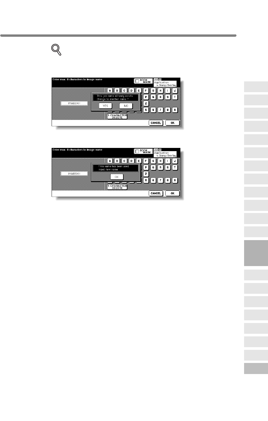
Storing an Overlay Image in HDD / Overlaying Image Stored in
HDD (Overlay Memory) (continued)
9-65
DETAILS: Popup Menu for Name Duplication
If the popup menu with YES and NO keys is displayed instead of the Basic
Screen, the entered name is duplicated. Touch YES to enter a new name, or
NO to create a duplicate name.
If the popup menu with OK key is displayed, the entered name is duplicated.
Touch OK, then enter a new name.
Changing the popup menu for duplicate name and displaying the IMAGE
DELETE key is available in the Memory switch No. 41 of the Key Operator
setting. See p. 13-39 ~ p. 13-44.
9
Applications
Reverse
Image
Non-Image
Area Erase
Program Job
Dual Page
Image Insert
OHP
Interleave
Booklet
Combination
Chapter
Sheet/Cover
Insertion
Application
Selection Screen
Repeat
Frame/Fold
Erasure
AUTO
Layout
Full-Image
Area
Image Shift
Reduce &
Shift
Stamp
Overlay
Overlay
Memory
9-66
blank page

10
10
Function
Image Recall
Image
Store&Output
Image
Store/Delete
Server
Functions
Image Store Function
To Use Server Functions....................................................................... 10-2
Storing/Deleting Image Data in HDD (Image Store/Delete).......... 10-4
Storing Image Data While Copying (Image Store&Output)................. 10-11
Recalling Image Data from HDD (Image Recall)...................... 10-14
How to Use Server Functions
Image Store
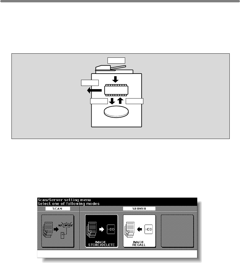
10-2
To Use Server Functions
Use Server function with HDD to accumulate scanned images into built-in DIMM
(memory), then store the image data in HDD so that the data can be recalled to DIMM
and output as needed. This function also allows you to store the image data for normal
copying procedures.
1 Image Store/Delete mode
HDD
DIMM
Scan
Store Recall
Output
Server Function with HDD
The Server function provides the following modes:
Store the image data scanned from originals in HDD, transmit the data from HDD,
or delete the data stored in HDD.
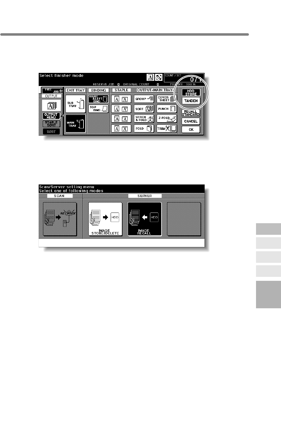
To Use Server Functions (continued)
10-3
2 Image Store & Output mode
Store the scanned image data in HDD after copying is completed.
3 Image Recall mode
10
Function
Image Recall
Image
Store&Output
Image
Store/Delete
Server
Functions
Recall the image data stored in HDD to built-in DIMM for printing.
Image Store
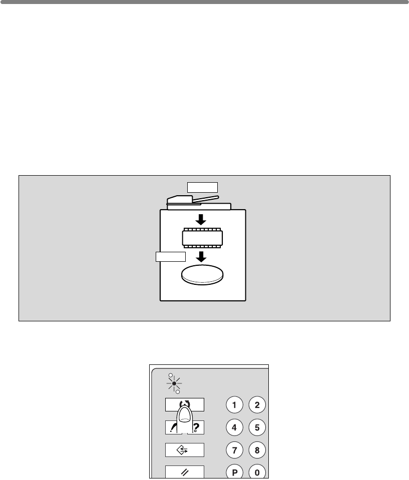
10-4
be given an alphabetical job name.
paper size (APS is automatically selected), Setting print quantity, Rotation, FULL
AREA in Non STD Size, Sheet/Cover Insertion, Chapter, Combination, Booklet, OHP
Interleave, Image Insert, Dual Page, Program Job (available in Image Store&Output
Mode only), Non-Image Area Erase, Reverse Image, Repeat, AUTO Layout, Image
Shift, Stamp/Overlay
1.
HDD
DIMM
Scan
Store
❒
Incompatible Scanning Conditions: 1u2, 2u2, AMS, Selecting output mode, Selecting
Storing/Deleting Image Data in HDD (Image Store/Delete)
>>>Specifications for Storing Image Data in HDD<<<
Use this function to store, retreive and delete the image data into/from HDD.
To Store Image Data in HDD
Specify your password when storing the data in HDD for protection. Image data can
CHECK
COPY
PRINT
JOB MEMORY
HELP
SCAN
Press [MODE] to light up the [SCAN] LED.
The Scan Setting Menu Screen will be displayed.
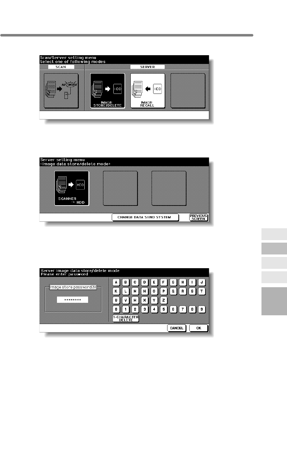
10-5
2. Touch IMAGE STORE/DELETE.
The Image Data Store/Delete Site Selection Screen will be displayed.
3.
The Image Data Password Entry Screen will be displayed.
4. Enter the desired image data password in up to 8 characters from the
touch screen keypad.
To correct an entry, touch 1-CHARACTER DELETE repeatedly to delete each
character, then enter the correct password.
5. If the password is correct, touch OK.
The Job Name Entry Screen will be displayed.
10
Function
Image Recall
Image
Store&Output
Image
Store/Delete
Server
Functions
Touch SCANNER→ HDD.
Storing/Deleting Image Data in HDD (Image Store/Delete) (continued)
Image Store
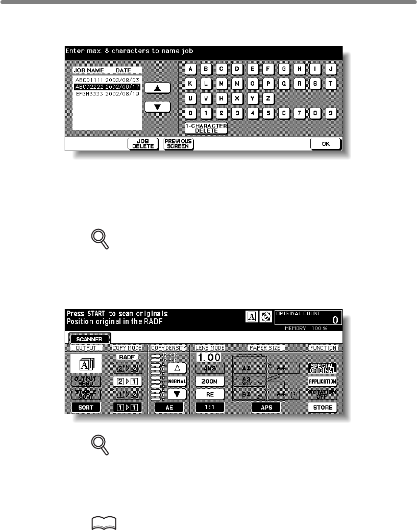
10-6
6. Enter the desired job name in up to 8 characters from the touch
screen keypad.
To correct an entry, touch 1-CHARACTER DELETE repeatedly to delete each
character, then enter the correct job name.
7. If the job name is correct, touch OK.
The Scanner Setting Screen will be displayed.
DETAILS
If an entered job name has already been used, the popup menu appears to
ask you whether to rewrite the data or to re-enter new name.
Touch YES to rewrite, or NO to create new name.
8. Select the desired scanning conditions.
DETAILS
Print quantity cannot be entered.
Store mode is available. Touch STORE to highlight it to use this function.
9. Position original(s) FACE UP in the document feeder or FACE DOWN
on the platen glass.
HINT
See p. 3-2 to p. 3-6 for details on positioning originals.
10. Press [START] to scan original(s).
When scanning originals is completed, the machine automatically begins storing data in
the HDD. If Store mode is used, touch to deselect STORE on the Scanner Setting
Screen after all originals are scanned, then press [START].
When storing job is almost completed, SCANNER→ HDD icon appears in the
message area, then the Basic Screen will be restored automatically.
Storing/Deleting Image Data in HDD (Image Store/Delete) (continued)
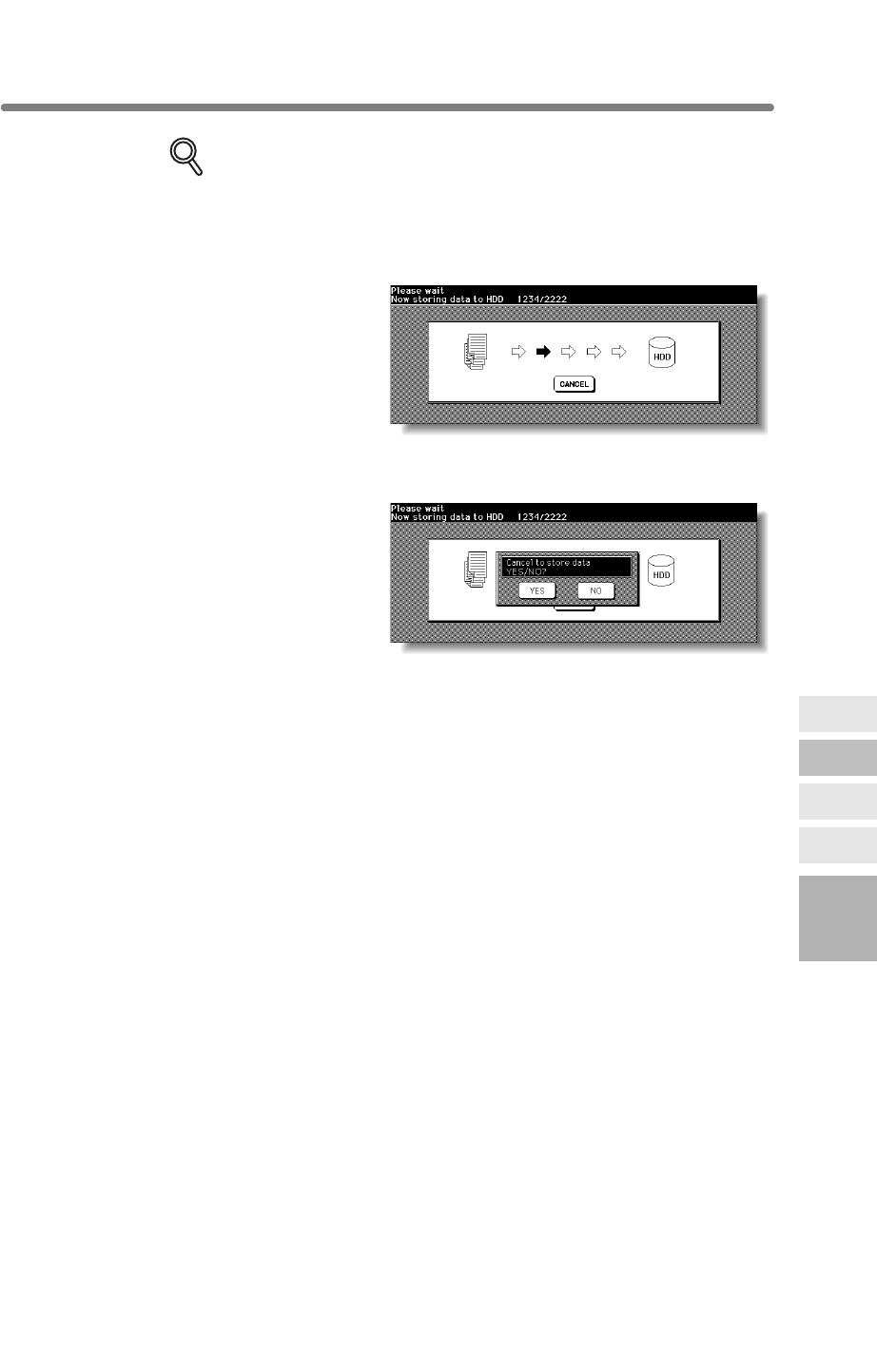
10-7
DETAILS
Key Operator can set the machine to restore the Job Name Entry Screen
when the storing job is completed, so that the data storing can be continued.
See p. 13-39 to p. 13-44 for details.
In this case, the Image Data Storing Screen shown below will be displayed
On this screen, touch CANCEL to suspend the storing job, then touch YES
on the popup menu to delete the data, or touch NO to continue.
10
Function
Image Recall
Image
Store&Output
Image
Store/Delete
Server
Functions
while the image data is stored in HDD.
Storing/Deleting Image Data in HDD (Image Store/Delete) (continued)
Image Store
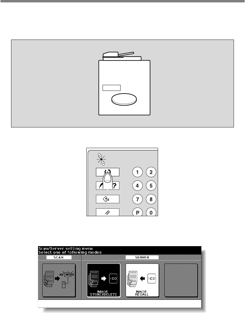
is to be specified by the given job name.
1.
2. Touch IMAGE STORE/DELETE.
The Image Data Store/Delete Site Selection Screen will be displayed.
HDD
Delete
CHECK
COPY
PRINT
JOB MEMORY
HELP
Storing/Deleting Image Data in HDD (Image Store/Delete) (continued)
To Delete Image Data from HDD
The password specified when storing the data in HDD is required. The image data
SCAN
10-8
Press [MODE] to light up the [SCAN] LED.
The Scan Setting Menu Screen will be displayed.
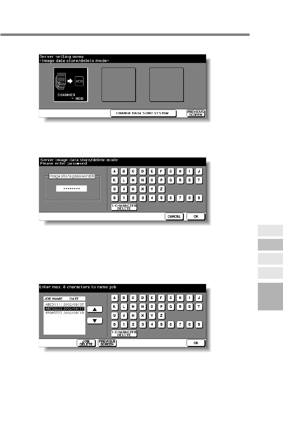
3.
The Image Data Password Entry Screen will be displayed.
4. Enter your image data password from the touch screen keypad.
To correct an entry, touch 1-CHARACTER DELETE repeatedly to delete each
character, then enter the correct job name.
5. Touch OK.
The Job Name Entry Screen will be displayed.
6. Delete the image data.
Touch the or key on the right side of the job name list to highlight the name of the
data to be deleted, then touch JOB DELETE.
10
Function
Image Recall
Image
Store&Output
Image
Store/Delete
Server
Functions
Storing/Deleting Image Data in HDD (Image Store/Delete) (continued)
Touch SCANNER→ HDD.
10-9
Image Store
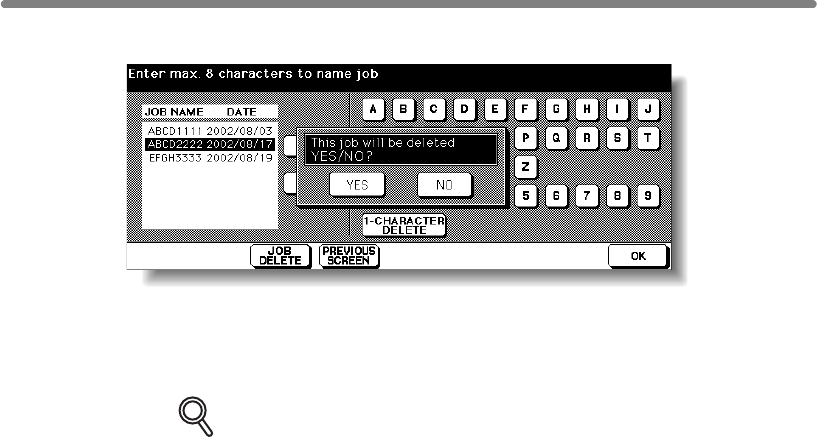
The popup menu will appear to confirm that you want to delete the selected data.
Touch YES to delete the selected data, or touch NO to cancel. The popup menu will
disappear.
7. Touch OK to restore the Scan/Server Setting Menu Screen.
DETAILS
To delete the data stored with different password, touch PREVIOUS
SCREEN to return to the Image Data Password Entry Screen.
8. Press [MODE] to light up the [COPY] LED.
The Basic Screen will be restored.
Storing/Deleting Image Data in HDD (Image Store/Delete) (continued)
10-10
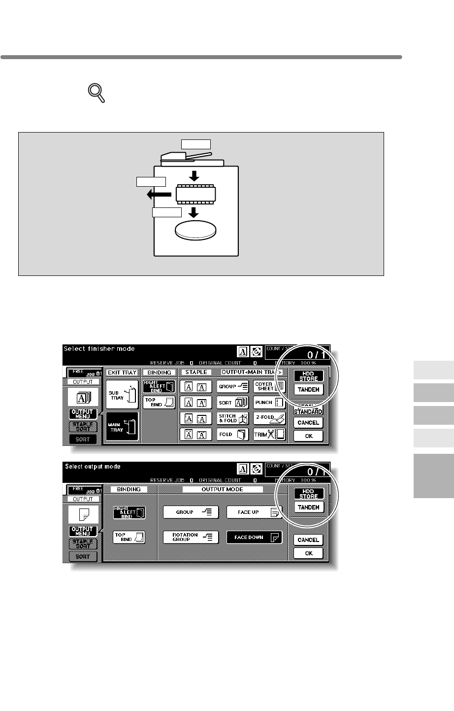
Storing Image Data While Copying (Image Store&Output)
Use this function to store the scanned image data in HDD after copying is completed.
DETAILS
This storing function does not conflict with any copying condition other than
Program Job.
1. Touch OUTPUT MENU on the Basic Screen to display the Output
Mode popup menu.
2. Touch HDD STORE.
The Image Data Password Entry Screen will be displayed.
HDD
DIMM
Scan
Store
Output
Function
Image Recall
Image
Store&Output
Image
Store/Delete
Server
Functions
10-11
10
Image Store
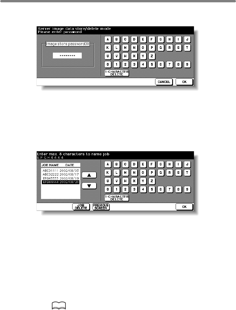
Storing Image Data While Copying (Image Store&Output) (continued)
3. Enter the desired image data password in up to 8 characters from the
touch screen keypad.
To correct an entry, touch 1-CHARACTER DELETE repeatedly to delete each
character, then enter the correct password.
4. If the password is correct, touch OK.
The Job Name Entry Screen will be displayed.
5. Enter the desired job name in up to 8 characters from the touch
screen keypad.
To correct an entry, touch 1-CHARACTER DELETE repeatedly to delete each
character, then enter the correct job name.
6. If the job name is correct, touch OK twice to return to the Basic
Screen.
The HDD icon is displayed in the message area of the Basic Screen.
7. Select the desired copying conditions, then enter the desired print
quantity.
8. Position original(s) FACE UP in the document feeder or FACE DOWN
on the platen glass.
HINT
See p. 3-2 to p. 3-6 for details on positioning originals.
9. Press [START] to scan and then print.
When the Store mode is used, touch STORE on the Basic Screen to deselect the
Store mode when the store function is completed, i.e., after all originals are scanned,
then press [START] to print.
10-12
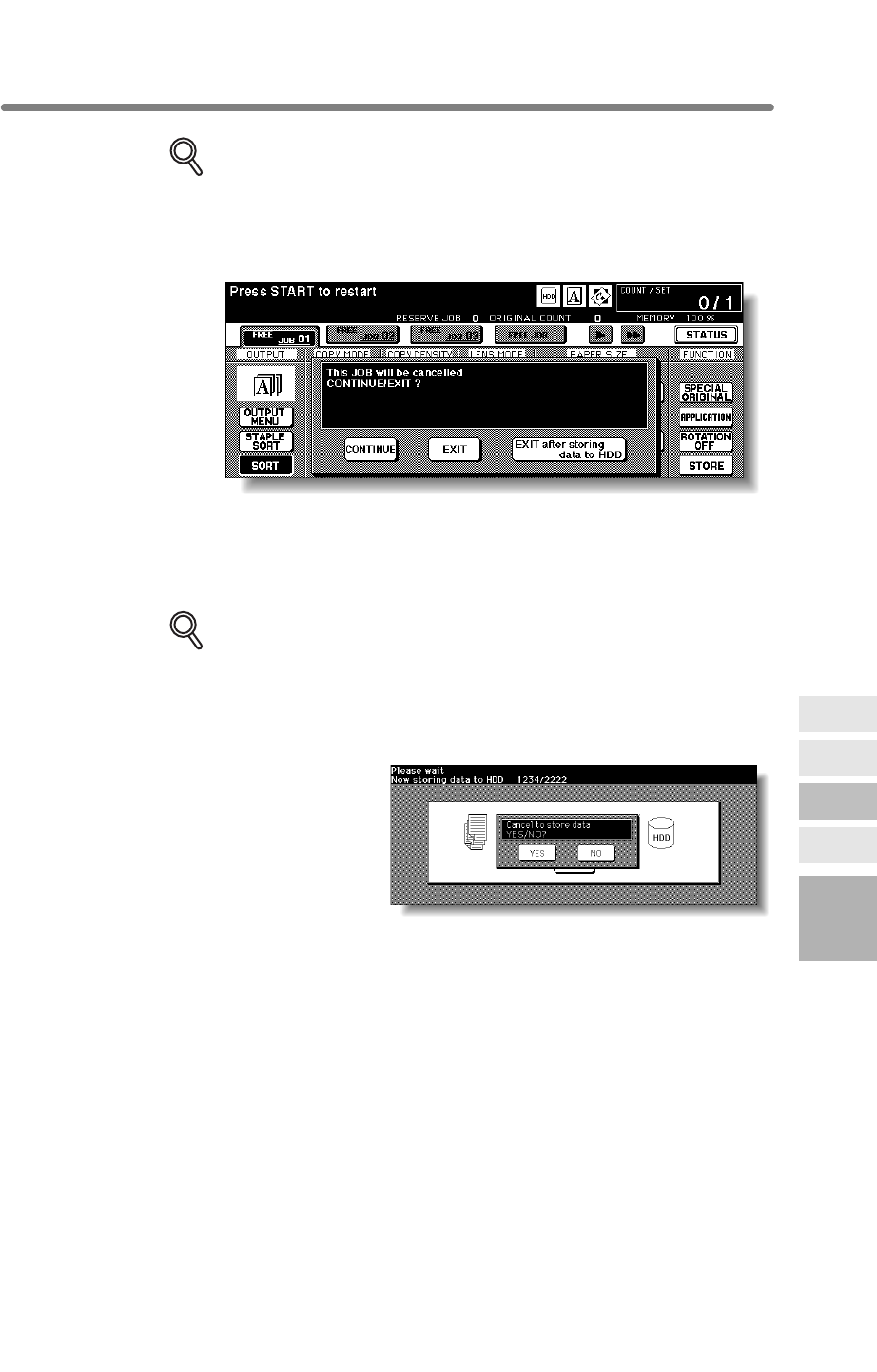
Storing Image Data While Copying (Image Store&Output) (continued)
DETAILS
To suspend the scanning or printing job, press [STOP] on the control panel.
The popup menu will be displayed to ask you how to complete the current
job. Touch CONTINUE to continue the job, EXIT to cancel the job and delete
the data, or EXIT after storing data to HDD to store the data in HDD
without printing.
After scanning all the originals, the machine automatically starts to print and store the
data in HDD.
When storing job is almost completed, SCANNER→ HDD icon appears in the
message area. Press [AUTO RESET] to restore the initial settings.
DETAILS
If the Memory Switch No. 43 is turned on in the Key Operator setting, the
Image Data Storing Screen will be displayed while the image data is stored
in HDD. (See p. 13-39 to p. 13-44 for details.)
In this case, touch CANCEL on the Image Data Storing Screen to suspend
the storing job, then touch YES on the popup menu to delete the data, or
touch NO to continue.
Function
Image Recall
Image
Store&Output
Image
Store/Delete
Server
Functions
10-13
10
Image Store
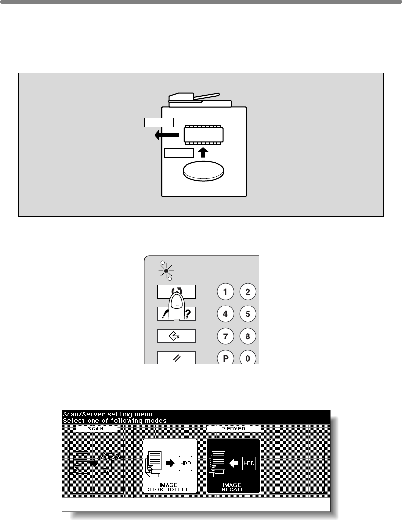
stored, then designate it by the job name.
1.
2. Touch IMAGE RECALL.
The Image Data Password Entry Screen will be displayed.
HDD
DIMM
Output
Recall
CHECK
COPY
PRINT
JOB MEMORY
HELP
Recalling Image Data from HDD (Image Recall)
Use this function to recall the image data from the HDD to the built-in DIMM for printing.
To recall data stored in the HDD, enter the password specified at the time data was
SCAN
10-14
Press [MODE] to light up the [SCAN] LED.
The Scan Setting Menu Screen will be displayed.
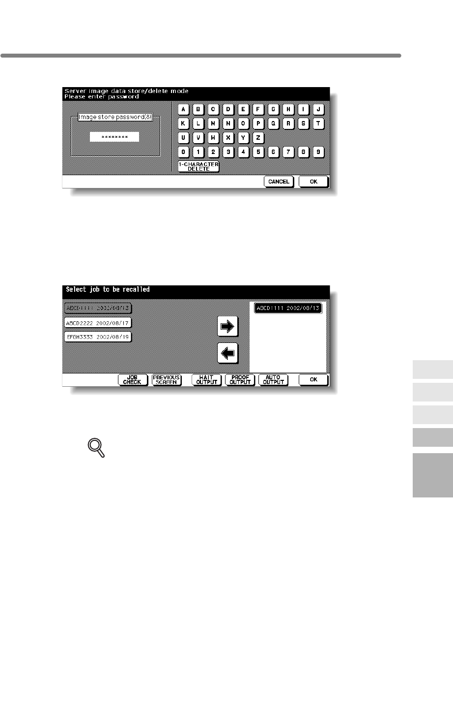
3. Enter your image data password from the touch screen keypad.
To correct an entry, touch 1-CHARACTER DELETE repeatedly to delete each
character, then enter the correct job name.
4. Touch OK.
The Recall Job Selection Screen will be displayed.
5. Select the job to be recalled.
view all the feature selections made for that job.
DETAILS
More than one job at a time can be moved to the recall list to be output in
succession, provided that those jobs have been stored with the same
copying conditions.
To cancel the job moved to the recall list, touch the job name in the list to
10
Function
Image Recall
Image
Store&Output
Image
Store/Delete
Server
Functions
on the right side. Touching JOB CHECK displays the Check Screen to allow you to
highlight it, then touch Å to return it to the left side key.
Touch the desired job name key to highlight it, then touch Âto move it to the recall list
Recalling Image Data from HDD (Image Recall) (continued)
10-15
Image Store
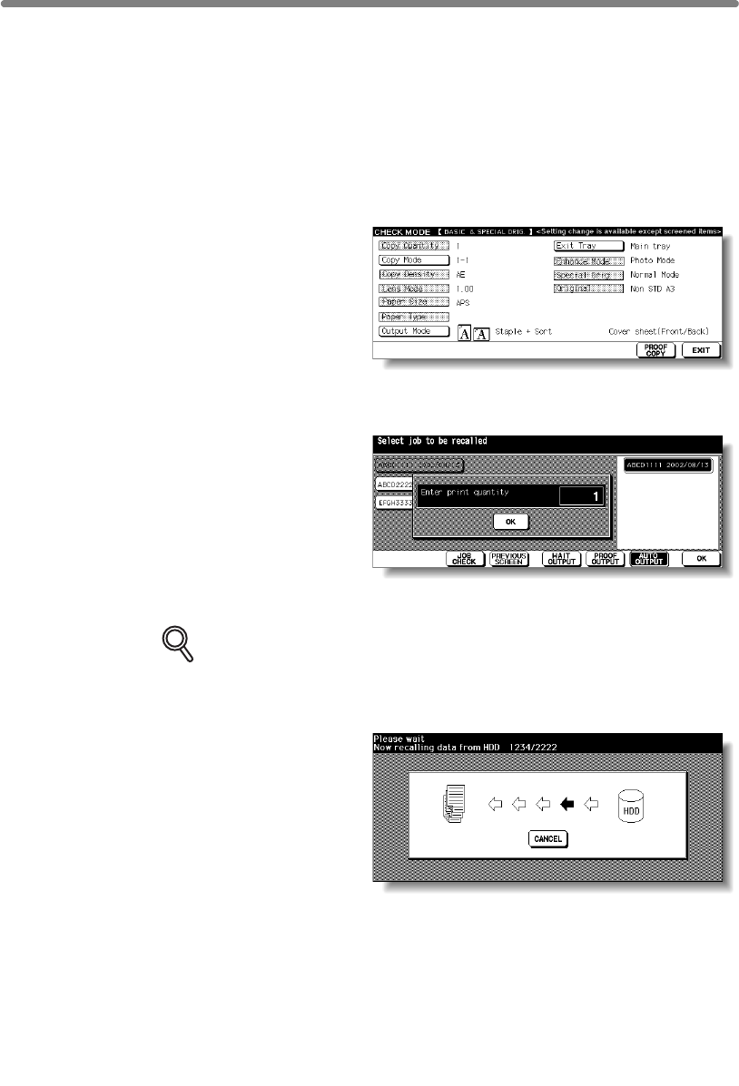
6. If the desired job name is displayed in the recall list, touch WAIT
OUTPUT, PROOF OUTPUT, or AUTO OUTPUT, as desired.
Follow the procedure on the next page according to the selected output mode key to
complete the image recall and output operation.
Selecting WAIT OUTPUT:
(1) Touch OK. When the data transmission is completed, the Basic Screen will be
displayed reflecting the settings made for that job.
(2) Enter the desired print quantity, then press [START] to print.
Selecting PROOF OUTPUT:
(1) Touch OK. The data transmission
starts with the Basic Screen
restored. When the data
transmission is completed, a
sample copy is output, then the
Check Screen will be displayed.
(2) Check the sample copy, then
change the copy conditions if required.
Enter the desired print quantity, then press [START] to print.
Selecting AUTO OUTPUT:
(1) Touch OK. The popup menu to
enter the print quantity will be
displayed.
(2) Enter the desired print quantity, then
touch OK.
When the data transmission is
completed, the machine
automatically starts to print.
DETAILS
Key Operator can set the machine to return to the Recall Job Selection
Screen when printing job is completed, so that the data recalling can
continue. See p. 13-39 to p. 13-44.
In this case, the Image
Data Recalling Screen will
be displayed while the
data is recalled.
On this screen, touch
CANCEL to suspend
recalling. On the popup
menu displayed, touch
YES to delete the data
recalled to DIMM, or
touch NO to continue. The
Recalling Image Data from HDD (Image Recall) (continued)
data stored in HDD will not be erased by this operation.
10-16

11
11
Paper &
Original Info
Original
Information
Paper
Information
Paper and Original
Information
Paper Information ..................................................................................11-2
Original Information ...........................................................................11-8

11-2
Paper Information
This machine is equipped with the following trays for loading copy paper.
• Multi-sheet bypass tray
Also, the following equipment is provided for conveying/delivering copies.
• ADU (Automatic Duplex Unit)
Paper Weight
DETAILS
• Some 170 g/m2 paper types may not be punched easily.
• The tray specified as Thin or Tab paper cannot be used for duplex copying.
•
has difficulty with toner fixation. See p. 13-23 ~p. 13-24.
Paper Trays Weight
Tray 1, 2, and 3 60 ~ 90 g/m2
91 ~ 170 g/m2 for the tray specified as Thick1
171 ~ 200 g/m2 for the tray specified as Thick2
50 ~ 59 g/m2 for the tray specified as Thin
91 ~ 170 g/m2 for the tray specified as Tab paper
Multi-sheet bypass tray 60 ~ 90 g/m2
91 ~ 200 g/m2 when specified as Thick
50 ~ 59 g/m2 when specified as Thin
91 ~ 170 g/m2 when specified as Tab paper
Equipment Weight
ADU 60 ~ 200 g/m2
Finisher 50 ~ 200 g/m2
60 ~ 90 g/m2 for Stitch&Fold / Fold mode
Cover sheet feeder 50 ~ 200 g/m2
Punching unit
Punching/Z-Folding unit 50 ~ 170* g/m2
60 ~ 90 g/m2 for Z-Folding mode
Trimmer unit 60 ~ 90 g/m2
Exit tray 50 ~ 200 g/m2
• Finisher (Q3219A/·Q3220A)
• Cover Sheet Feeder (Q3221A)
• Exit tray (for the machine without Finisher)
• Punching Unit (Q3222A/Q5684A)
Refer to the following information on paper capacity for each.
• Punching / Z-Folding Unit (Q3223A/Q5685A)
• Trimmer Unit (Q3224A)
• Tray 1, 2 and 3 (Engine tray)
(Engine tray)
• HCI Q3637A/Q3638A Tray 4 /HCI)
HCI (Q3637A/Q3638A)
HCI can be specified as Thick3, irrespective of paper weight, for paper that

Paper Information (continued)
11-3
HINTS
•
• See p. 3-29 for Paper Type setting of Multi-sheet bypass tray.
Tray/ Exit Tray Capacity
Paper Trays Capacity
tray)
Tray 1 or 2: 500 sheets (80 g/m2)
Tray 3: 1,000 sheets (80 g/m2)
4,000 sheets (80 g/m2)
Multi-sheet bypass tray 150 sheets (80 g/m2)
1 sheet each for thick/thin paper and transparent film
Equipment Capacity
ADU Unlimited
Finisher
Secondary (sub) tray
200 sheets
Primary (main) tray
500 sheets (A5, A5R, B6R)
3,000 sheets (A4, A4R, B5R, 8.5"x11", 8.5"x11"R)
1,500 sheets (A3, F4, B4)
See the table for Staple-sort / Z-Fold mode on p. 11-4.
Booklet tray 100 sheets (A3, B4, 11"x17", 8.5"x14" in Fold / Stitch &
Fold mode)
Fold: 33 sets for 3-sheet-folded booklet
(99 sheets, 396 pages)
Stitch&Fold: 20 sets for 5-sheet-folded booklet
(100 sheets, 400 pages)
5 sets for 20-sheet-folded booklet
(100 sheets, 400 pages)
* Maximum number of folded sheet is 3 for Fold mode,
and 20 for Stitch&Fold mode.
200 sheets (200g/m2) for each
Unlimited
Punch: Unlimited
Z-Fold: 1 sheet only
Approx. 512 sheets max.
100 sets max. of 2~5-sheet-folded booklet
50 sets max. of 6~10-sheet-folded booklet
32 sets max. of 11~16-sheet-folded booklet
Exit tray 100 sheets
11
Paper &
Original Info
Original
Information
Paper
Information
(Q3219A/
Q3220A
Cover sheet feeder Q3221A
Punching unit (Q3222A/Q5684A)
Finisher
Q3220A
Punching / Z-Folding
unit (Q3223A/Q5685A)
Trimmer unit (Q3224A)
Tray 1, 2, and 3 (Engine
See p. 13-23 for Paper Type setting of Tray 1, 2, 3 or HCI.
HCI (Q3637A/Q3638A)
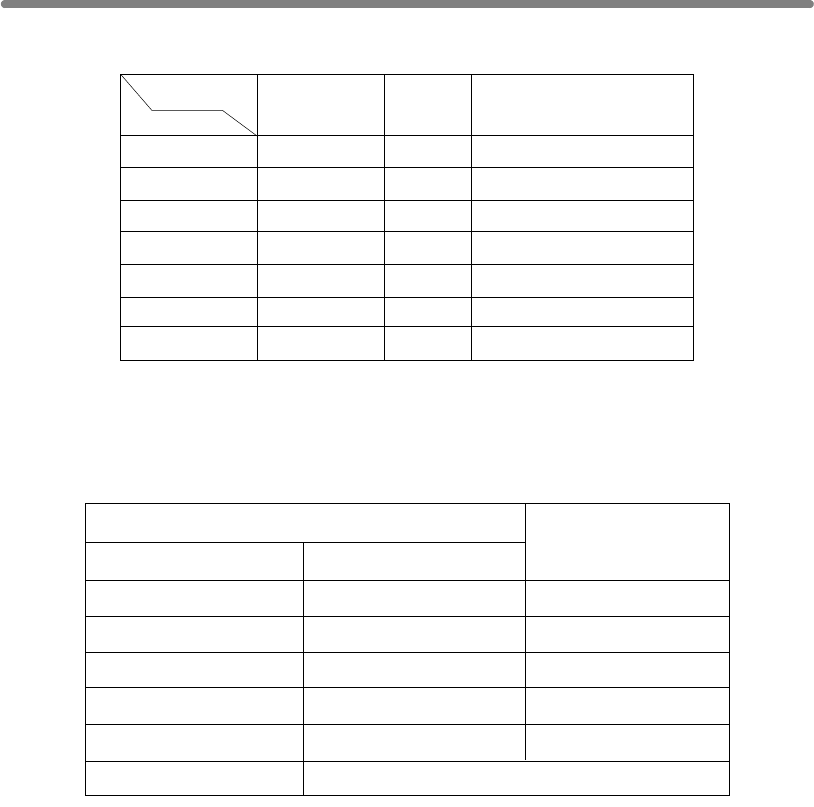
Paper Information (continued)
11-4
2~9
10~20
21~30
31~40
41~50
51~60*
61~100*
50 sets
50
30
25
20
-
-
50 sets
50
30
25
20
15
10
100 sets
50
30
25
20
15
10
A3/A3W
(11"x17"/11"x17"W)
A5/A5W
(5.5"x8.5")
B4/B4R, A4/A4W, A4R/A4WR,
B5/B5W (8.5"x14", 8.5"x11"/
8.5"x11"W, 8.5"x11"R/8.5"x11"WR)
Paper size
No. of copies
1 sheet
2
3
4
5
6 or more
1 ~ 40 sheets
0 ~ 30
0 ~ 20
0 ~ 10
0
20 stapled sets
10
4
3
2
Primary Tray Capacity
Capacity for one stapled set
Number of Z-folded sheets
Number of regular sheets
Staple-Sort is unavailable with Z-Fold.
Capacity for Mixed Size Originals
using Z-Fold and Staple-Sort
Paper Capacity for Staple-sort mode of Q3219A/Q3220A Finisher
*51 ~ 100 copies can be stapled by Q3219A Finisher only.
Paper Information (continued)
11-5
Paper Size
HINTS
• F4; 203mm x 330mm
A3; 297mm x 420mm
B4; 257mm x 364mm
A4; 210mm x 297mm
B5; 182mm x 257mm
A5; 148mm x 210mm
•
to p. 13-24.
•
Paper Trays Available Sizes
Tray 1, 2, and 3 STD size: A3, B4, F4, A4, A4R, B5, B5R, A5*, 11"x17",
8.5"x14", 8.5"x11"
*Portrait orientation only.
STD (special):
Detects 8.5"x11"R instead of A4R or F4, and detects
5.5"x8.5" instead of A5.
Non STD size:
Max. 314mm x 445mm ~ Min. 210mm x 140mm
Wide size: A3W, B4W, F4W, A4W, A4WR, B5W, A5W,
11"x17"W, 8.5"x11"W, 5.5"x8.5"W
A4 fixed (can be changed to the following sizes)
STD size:
B5, 8.5"x11"
Non STD size:
Max. 314mm x 223mm ~ Min. 257mm x 182mm
Wide size:
A4W, B5W, 8.5"x11"W
A3 fixed (can be changed to the following sizes)
STD size: B4, F4, A4, A4R, 11"x17", 8.5"x14", 8.5"x11",
8.5"x11"R
Non STD size:
Max. 314mm x 459mm ~ Min. 257mm x 210mm
Wide size: A3W, B4W, F4W, A4W, A4WR, 11"x17"W,
8.5"x14"W, 8.5"x11"W, 8.5"x11"WR
Paper Trays Available Sizes
Multi-sheet bypass tray STD size: A3, B4, F4, A4, A4R, B5, B5R, A5,
A5R, A6R, 11"x17", 8.5"x11"
STD (special):
Detects 8.5"x11"R or F4 instead of A4R,
5.5"x8.5" instead of A5 or A5R.
Non STD size:
Max. 314mm x 459mm ~ Min. 100mm x
148mm
Wide size: A3W, B4W, F4W, A4W, A4WR, B5W,
B5WR, A5W, A5WR, 11"x17"W, 8.5"x11"W,
8.5"x11"WR, 5.5"x8.5"W, 5.5"x8.5"WR,
11
Paper &
Original Info
Original
Information
Paper
Information
Contact your service representative to change the tray size, if desired.
Q3637A is initially fixed to A4, and Q3638A is fixed to A3.
(Engine tray)
For special size setting of engine trays (Tray 1, 2, and 3), see p. 13-23
HCI (Q3637A)
HCI (Q3638A)
Paper Information (continued)
11-6
HINT
See p. 3-29 to p. 3-31 for specifying the special paper size of the Multi-sheet
bypass tray.
Equipment Available Sizes
ADU STD size / STD (special):
A3 to A5*
*Portrait orientation only.
Non STD size:
Unavailable
Wide size: A3W to A5W*
*Portrait orientation only.
Fold mode)
Punching mode:
Z-Folding mode:
fold)
double-fold.
A3, B4, A4R, 8.5"x11"R and those wide sizes
Max. 314mm x 459mm ~ Min. 100mm x 148mm
(A3, B4, A4R, 8.5"x11"R only in Stitch&Fold /
Max. 314mm x 459mm ~ Min. 100mm x 148mm
Max. 314mm x 459mm ~ Min. A5
A3, B4, A4, B5, 11"x17", 8.5"x11"
A3, B4, A4,B5, 11"x17", 8.5"x11"
A3, B4, 11"x17" (z-fold), 8.5"x14" (double-
All other paper sizes will be output without z-fold/
Finisher (Q3219A/Q3220A)
Cover sheet feeder (Q3221A)
Punching unit (Q3222A/Q5684A)
Punching / Z-Folding unit
(Q3223A/Q5685A)
Trimmer unit (Q3224A)
Exit tray

Paper Information (continued)
11-7
Special Paper in Multi-Sheet Bypass Tray
Multi-sheet bypass tray accepts the following special paper type that cannot be loaded
Transparent film, labels, hole punch
DETAILS
When using special paper type other than the above mentioned, select
“User” as the paper type in Paper type/size setting for the Multi-sheet
bypass tray.
To Store Copy Paper
• Store paper in a cool, dry area.
Using damp copy paper may cause a paper misfeed.
Keep partially used packages tightly wrapped during storage.
• Do not place paper packages vertically to store.
Paper curl due to the vertical storage may cause a paper misfeed.
11
Paper &
Original Info
Original
Information
Paper
Information
in the engine trays.
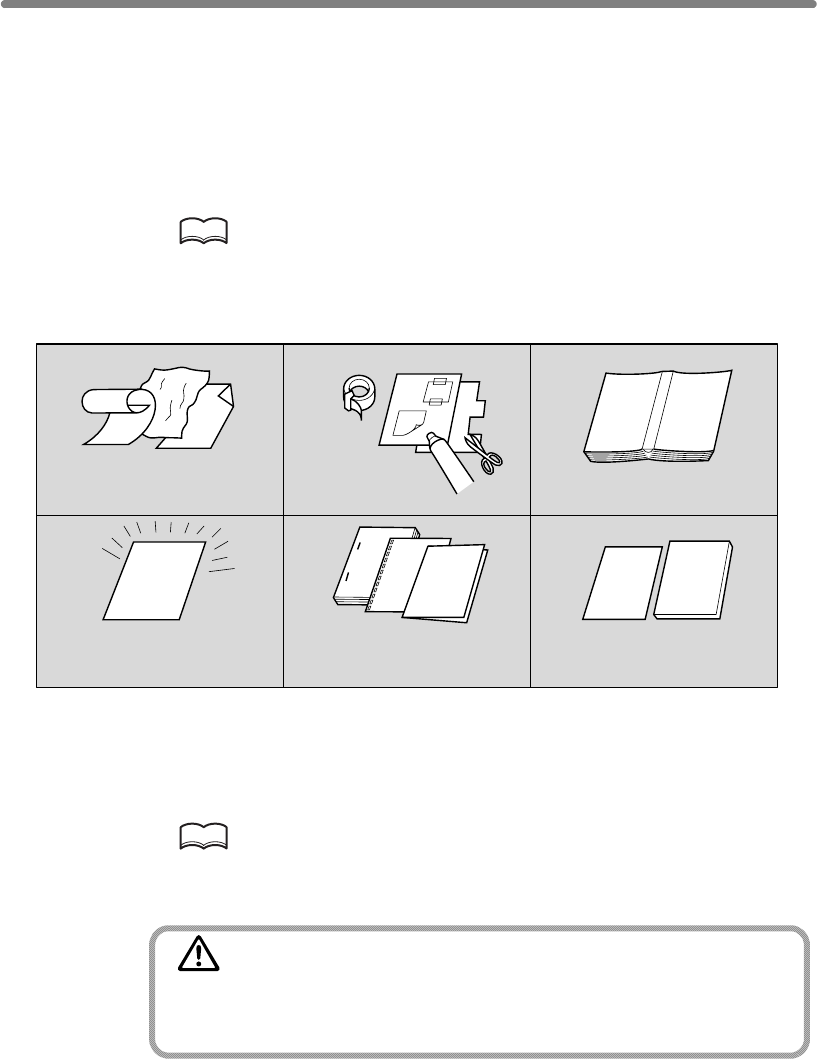
11-8
Original Information
Use the platen glass or document feeder to position originals to copy.
Platen Glass Originals
Use the platen glass when originals are not suitable for use with the document feeder,
e.g., when size is incompatible, or when originals are folded, stapled, torn, or in
generally poor condition.
HINT
See each description in this manual for copy conditions which cannot use
the document feeder to scan.
Platen Glass Original Specifications
❒Max. book weight/thickness: 6.8 kg / 30mm
❒Original placement: Face down on right depth side of glass
HINT
Detectable paper size can be changed from only A series to Inch series, AB
series, or AB series and Inch series mixed by Key Operator. See p. 13-39 to
p. 13-44.
CAUTION
Do not place too heavy originals, or do not press strongly when
thick original is placed and is under pressure of RADF;
otherwise the glass may be broken and you may be injured.
12
Curled, creased or
folded originals
Glossy or transparent
originals, OHP film,
art paper, cellophane
Paste-ups or
cut-outs Books
3
456
Doubled, punched or
stapled originals Thin or thick originals
❒Max. original size: A3, sheet or book
Unsuitable RADF Originals
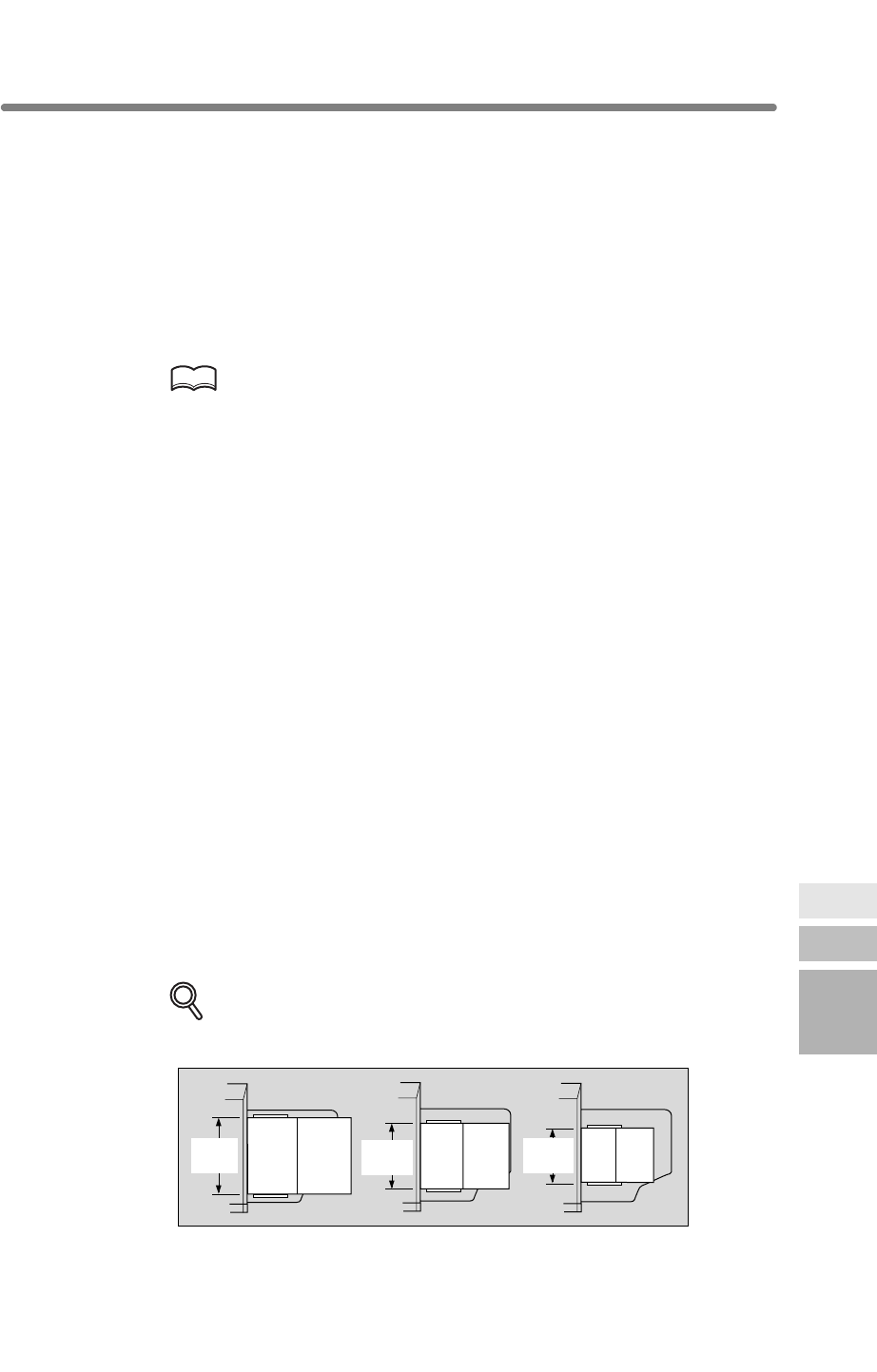
Original Information (continued)
11-9
• Normal mode
• Mixed Original mode
• Z-Folded Original mode
•SDF mode
Specifications for each mode are described as follows.
HINT
Detectable paper size can be changed from only A series to Inch series, AB
series, or AB series and Inch series mixed by Key Operator. See p. 13-39 to
p. 13-44.
Normal mode
❒Detectable original size:
A3, B4, F4, A4, A4R, B5, B5R, A5, A5R, 11"x17", 8.5"x11"
❒Original weight: 50 ~ 129 g/m2 (no special stock)
130 ~ 200 g/m2 SDF mode only
❒Max. feeder capacity: 100 sheets (80 g/m2 paper)
❒Curling tolerance: 10mm or less
❒Original placement: Face up
Mixed Original mode
Use Mixed Original mode to copy mixed size originals. See p. 8-6 for details.
B4, A4R, B5, B5R, and A5
mixed
A4R, B5R, and A5
mixed
B5R and A5R
mixed
❒Original weight: 50 ~ 129 g/m2 (no special stock)
❒Max. feeder capacity: 100 sheets (80 g/m2 paper)
❒Curling tolerance: 10mm or less
❒Original placement: Face up (see p. 3-3 for details.)
DETAILS
See below for the guide width of each combination.
A3A4 B4B5 A4
A5
Guide
width
Guide
width
Guide
width
11
Paper &
Original Info
Original
Information
Paper
Information
originals.
A3, B4, A4, A4R, B5, and A5
mixed
RADF Originals
Following four modes are provided when using the document feeder (RADF) to scan
❒Original size: Four types of size combination are determined by the RADF guide width.

Original Information (continued)
11-10
Z-Folded Original mode
❒Detectable original size:
A3, B4, F4, A4, A4R, B5, B5R, A5, A5R, 11"x17", 8.5"x11"
❒Original weight: 50 ~ 129 g/m2 (no special stock)
❒Max. feeder capacity: 100 sheets (80 g/m2 paper)
❒Curling tolerance: 10mm or less
❒Original placement: Face up; orientation same as copy paper
SDF mode
Use SDF mode to copy thick originals to be fed one sheet at a time in the document
feeder.
❒Detectable original size:
A3, B4, F4, A4, A4R, B5, B5R, A5, A5R, 11"x17", 8.5"x11"
❒Original weight: single-sided original 50 ~ 200 g/m2 paper
double-sided original 50 ~ 129 g/m2 paper
❒Max. feeder capacity: 1 sheet at a time
❒Original placement: Face up (see p. 8-10 ~ p. 8-11)
Use Z-Folded Original mode to scan folded originals without using the size detection
sensor of the RADF. See p. 8-8 for details.

12
12
Maintenance
& Supplies
Checking
Copy Count
Cleaning
Scanning
Section
Empty Trash
Basket
Inserting New
Staple Cartridge
Adding Toner
Punching (Z-Folding) Unit..................................................................... 12-9
Empty Waste Basket of Q3224A Trimmer Unit....................................12-11
Cleaning Image Scanning Section...................................................... 12-13
Checking Copy Count......................................................................... 12-15
Maintenance & Supplies
Adding Toner ........................................................................................ 12-2
Inserting a New Staple Cartridge into Q3219A/Q3220A Finisher ........ 12-5
Empty Waste Basket of Q3222A/Q5684A/Q3223A/Q5685A
How to Maintain the mfp
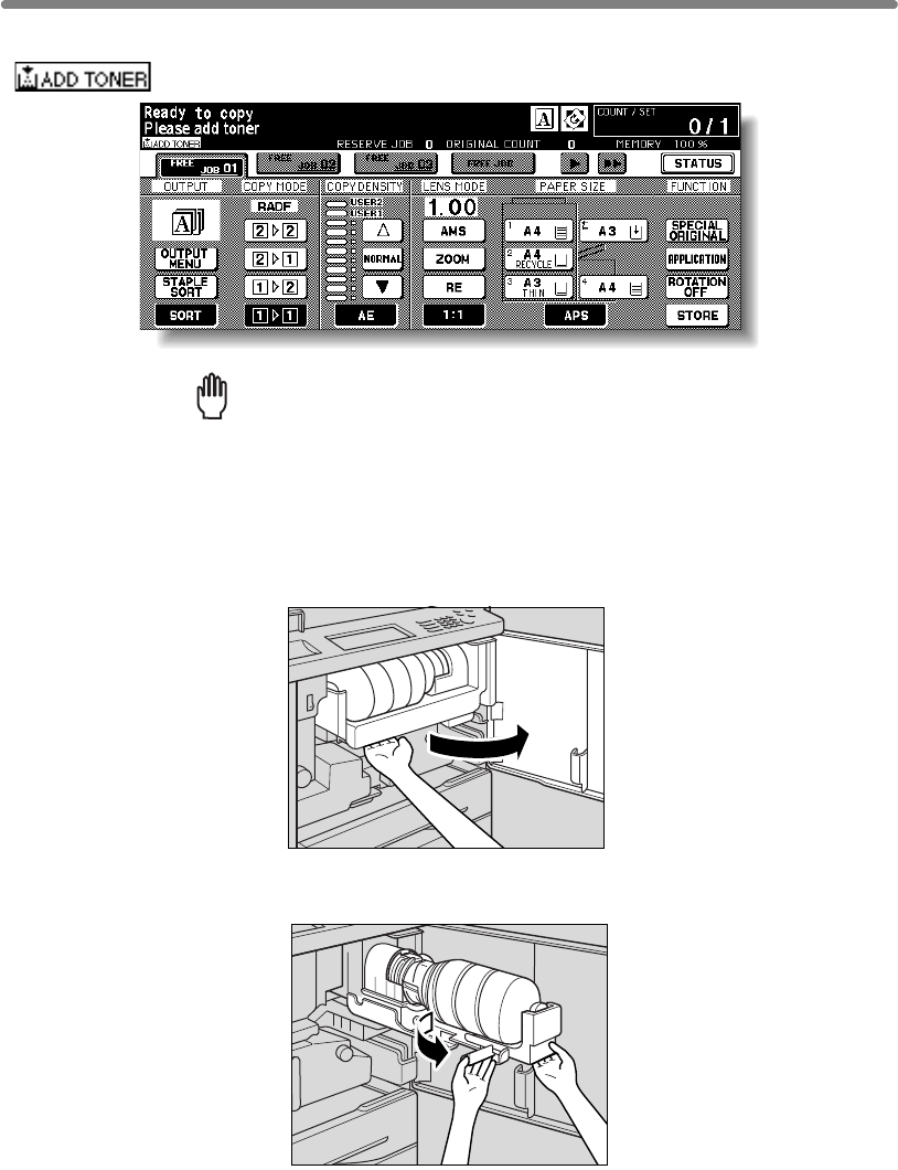
12-2
Adding Toner
When toner supply is low, the message “Please add toner” and the ADD TONER icon
( ) display on the touch screen.
Reminder!
Use the same number toner cartridge as described on the label on the front
of the toner box. Otherwise, machine trouble may occur.
Add toner according to the procedure as follows.
1.
the right.
2. Pull the toner cartridge lock lever forward until it stops.
Open the mfp front door, then pull out the toner box 90 degrees to
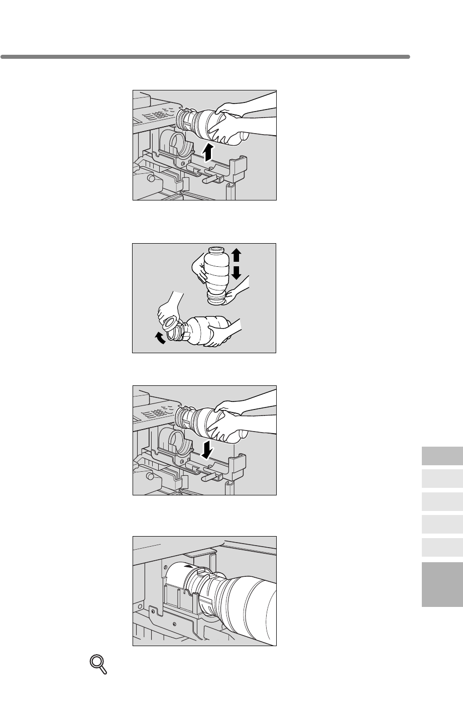
Adding Toner (continued)
12-3
3. Remove the empty toner cartridge.
4. Shake the new toner cartridge several times to loosen toner, then
remove the toner cartridge cap.
5. Set the new toner cartridge into the toner box.
6. Align the hollow part of the toner cartridge with the mark on the
toner box.
DETAILS
Be sure to set the hollow part of the toner cartridge upward, otherwise the
machine trouble may occur.
12
Maintenance
& Supplies
Checking
Copy Count
Cleaning
Scanning
Section
Empty Trash
Basket
Inserting New
Staple Cartridge
Adding Toner
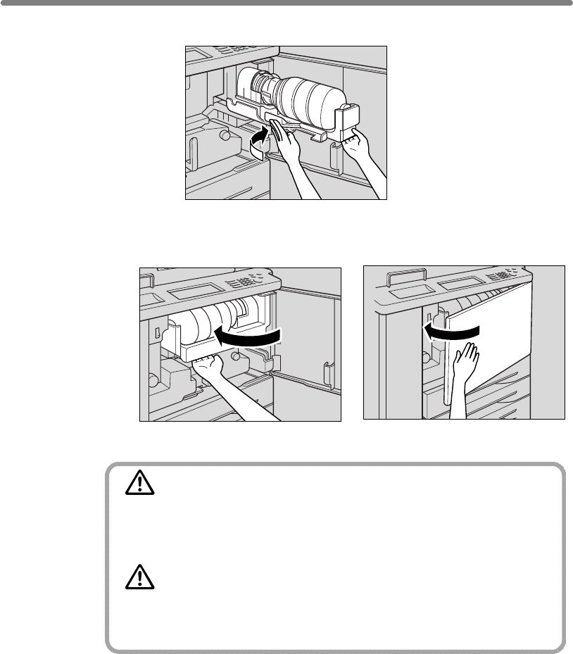
Adding Toner (continued)
12-4
7. Push the toner cartridge lock lever backward until it stops.
8.
front door securely.
CAUTION
Keep the toner cartridge away from children. The toner is non-
toxic; however if you inhale or contact with eyes by accident,
flush with water and seek medical advice.
CAUTION
Do not throw the empty toner cartridge into a fire. If it is thrown
into a fire, the toner may ignite and cause a dangerous situa-
tion.
Return the toner box to its original position, then close the mfp
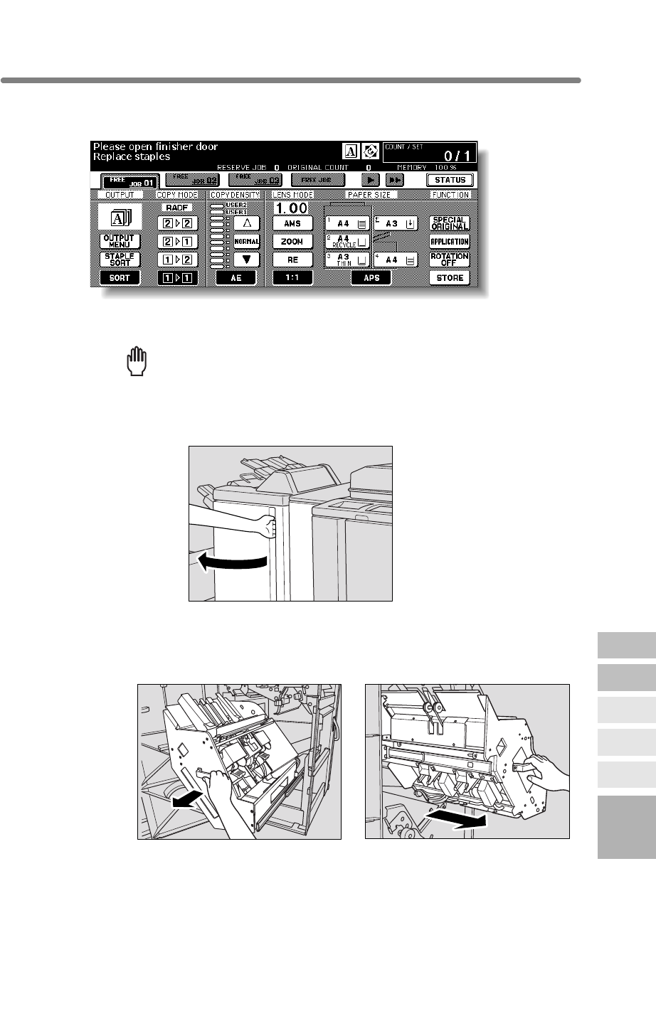
12-5
When the staple cartridge of the Finisher is empty, the Basic Screen displays the
following message in the message area.
Follow the procedure below according to your finisher type to replace the staple cartridge.
Reminder!
1. Open the Finisher door.
2. Pull out the stacker unit slowly by holding the stacker unit handle
until it stops.
12
Maintenance
& Supplies
Checking
Copy Count
Cleaning
Scanning
Section
Empty Waste
Basket
Inserting New
Staple Cartridge
Adding Toner
Inserting a New Staple Cartridge into Q3219A/Q3220A Finisher
Use only the staples supplied by hp. To purchase, please contact
Q3219A Q3220A
your service representative.
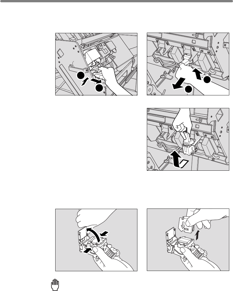
12-6
3. Pull up the cartridge housing, then remove it while sliding it along the
stapler rail.
4.
Open the bottom of the cartridge housing while pressing two locks on both sides.
Reminder!
Do not remove the staples remaining inside the housing; otherwise, the first
sheet output after the replenishment will not be stapled.
2
1
1
2
Q3219A Q3220A
Inserting a New Staple Cartridge into Q3219A/Q3220A Finisher (continued)
FQ3220A
Q3219A: Open the bottom of the cartridge housing, then remove
the empty cartridge.
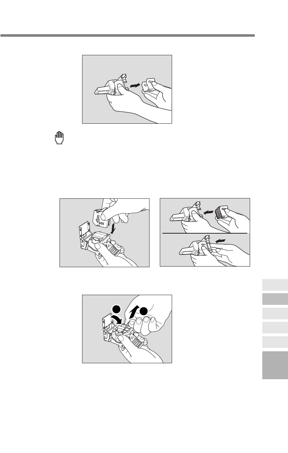
12-7
Reminder!
Do not remove the staples remaining inside the housing; otherwise, the first
sheet output after the replenishment will not be stapled.
5. Insert the new cartridge into the housing.
Firmly insert the cartridge into the housing while the arrow indication on the cartridge
appears as shown below.
6.
1
2
12
Maintenance
& Supplies
Checking
Copy Count
Cleaning
Scanning
Section
Empty Trash
Basket
Inserting New
Staple Cartridge
Adding Toner
Inserting a New Staple Cartridge into Q3219A/Q3220A Finisher (continued)
Q3220A: Remove the empty cartridge from the cartridge housing.
Q3219A Q3220A
Q3219A: Remove the lock tape from the cartridge, then close
the bottom of the housing.
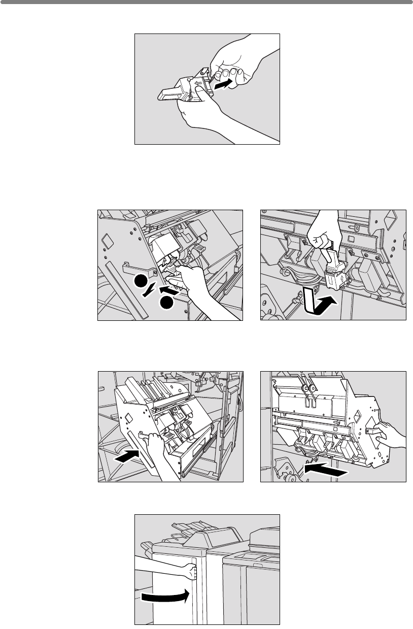
12-8
7. Insert the cartridge housing while sliding it along the stapler rail, then
push down and in to secure it in place.
9. Return the stacker unit to its original position.
9. Close the Finisher door.
2
1
Inserting a New Staple Cartridge into Q3219A/Q3220A Finisher (continued)
Q3219A Q3220A
Q3219A Q3220A
Q3220A: Remove the lock tape from the cartridge.
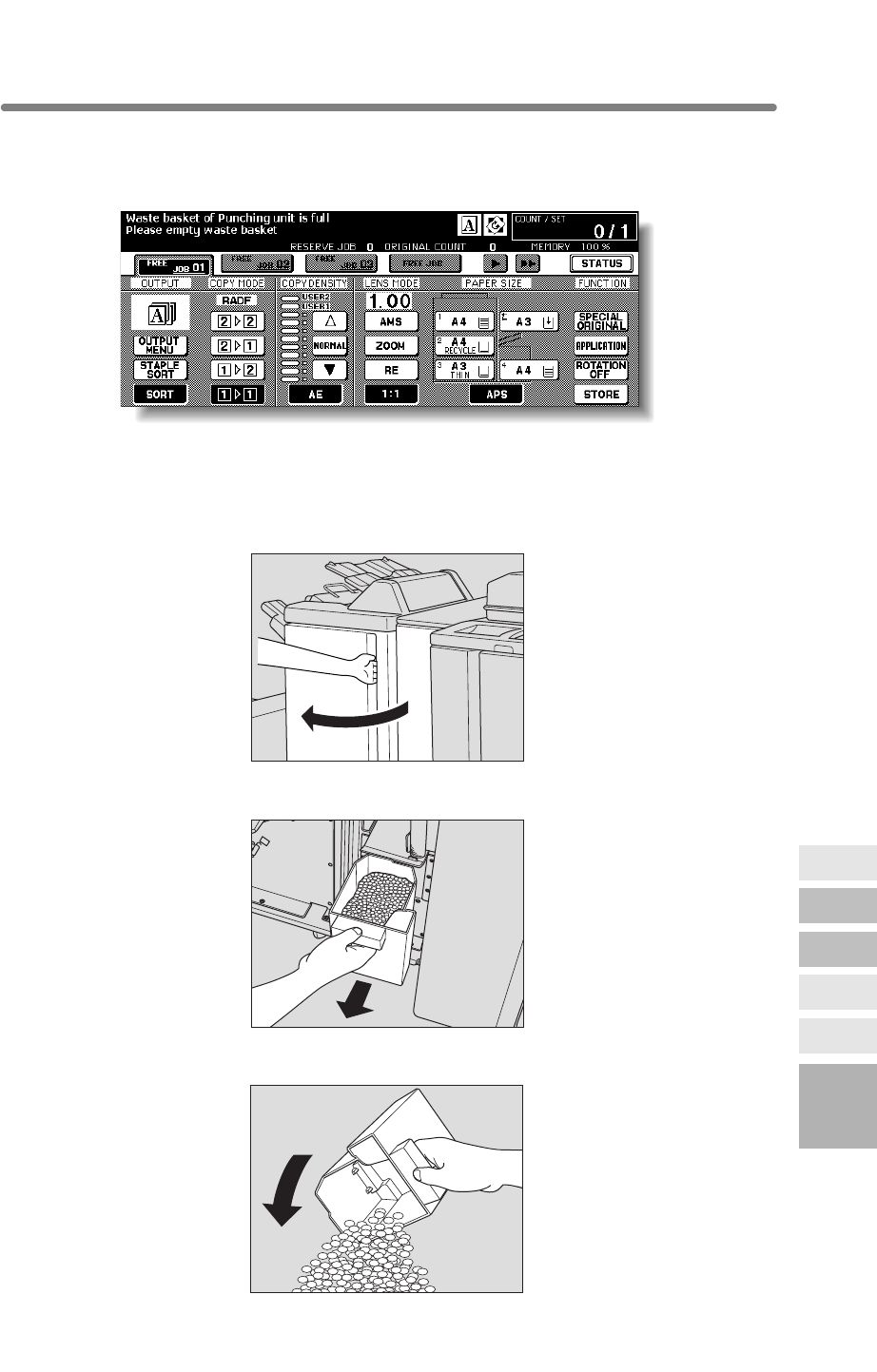
12-9
When the waste basket becomes full, “Waste basket of Punching unit is full / Please
empty waste basket” message will be displayed on the touch screen, and the finished
set will be output without being punched even if Punch mode is selected.
Follow the procedure below to empty the waste basket.
1. Open the Punching/Z-Folding unit front door with Finisher door han-
dle.
2. Withdraw the waste basket.
3. Empty the waste basket.
12
Maintenance
& Supplies
Checking
Copy Count
Cleaning
Scanning
Section
Empty Trash
Basket
Inserting New
Staple Cartridge
Adding Toner
Empty Waste Basket of Q3222A/Q5684A/Q3223A/Q5685A Punching (Z-Folding) Unit
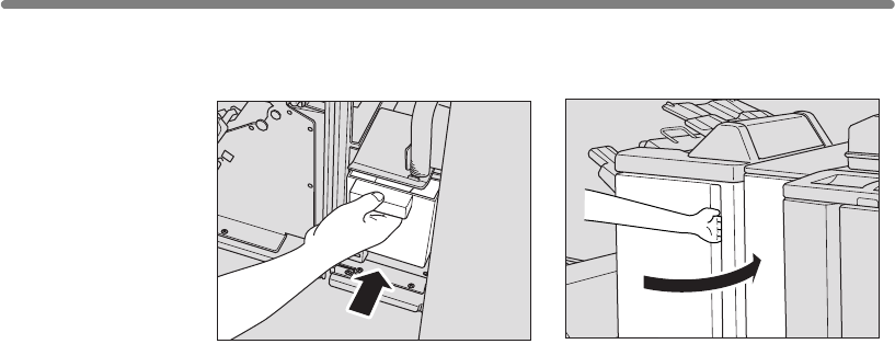
12-10
4. Return the waste basket to its original position, then close the Punch-
ing/Z-Folding unit front door securely.
Empty Waste Basket of Q3222A/Q5684A/Q3223A/Q5685A Punching (Z-Folding) Unit (continued)
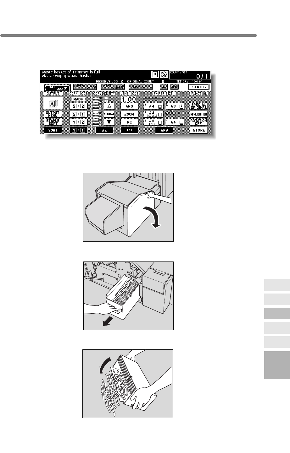
12-11
When the waste basket becomes full, “Waste basket of Trimmer is full / Please empty
waste basket” message will be displayed on the touch screen, and the finished set will
be output without being trimmed even if Trimming mode is selected.
Follow the procedure below to empty the waste basket.
1. Open the trimmer front door.
2. Withdraw the waste basket.
3. Empty the waste basket.
12
Maintenance
& Supplies
Checking
Copy Count
Cleaning
Scanning
Section
Empty Trash
Basket
Inserting New
Staple Cartridge
Adding Toner
Empty Waste Basket of Q3224A Trimmer Unit
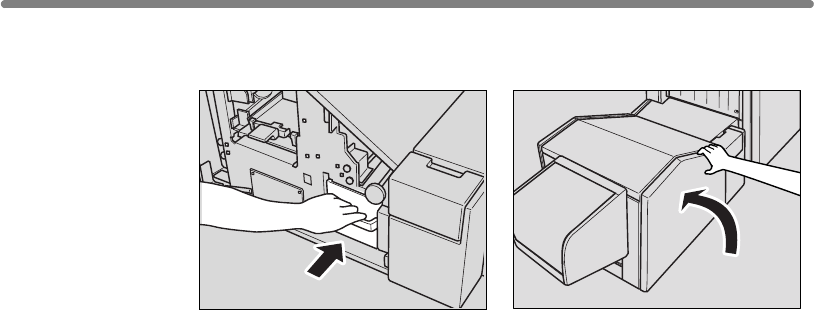
12-12
4. Return the waste basket to its original position, then close the
trimmer front door securely.
Empty Waste Basket of Q3224A Trimmer Unit (continued)
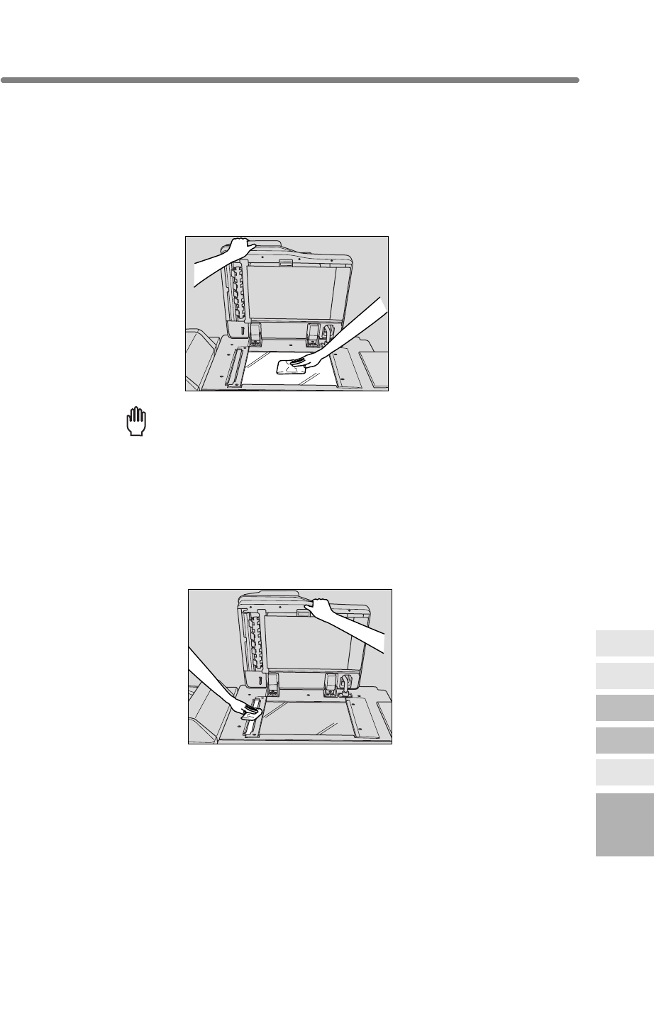
12-13
Cleaning Image Scanning Section
In order to maintain optimum copy quality, always keep the following areas clean.
Cleaning the Document Glass
Raise the document cover, and clean the glass with a clean soft cloth.
The glass may also be cleaned with a soft cloth dampened slightly with water, if it is dif-
ficult to clean.
Reminder!
Never use paint solvents, such as benzene or thinners, to clean the platen
glass.
Cleaning the Left Partition Glass
Keep the glass clean; otherwise soil marks may be copied, resulting in dark lines on the
copies.
Raise the document cover, and clean the left partition glass with a clean soft cloth.
12
Maintenance
& Supplies
Checking
Copy Count
Cleaning
Scanning
Section
Empty Trash
Basket
Inserting New
Staple Cartridge
Adding Toner
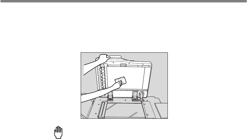
Cleaning Image Scanning Section (continued)
12-14
Reminder!
copied or the original size cannot be detected correctly.
cloth.
platen guide cover.
Cleaning the RADF Platen Guide Cover
The RADF platen guide cover should be kept clean; otherwise soil marks may be
Raise the document cover, and clean the RADF platen guide cover with a clean soft
Never use paint solvents, such as benzene or thinners, to clean the RADF
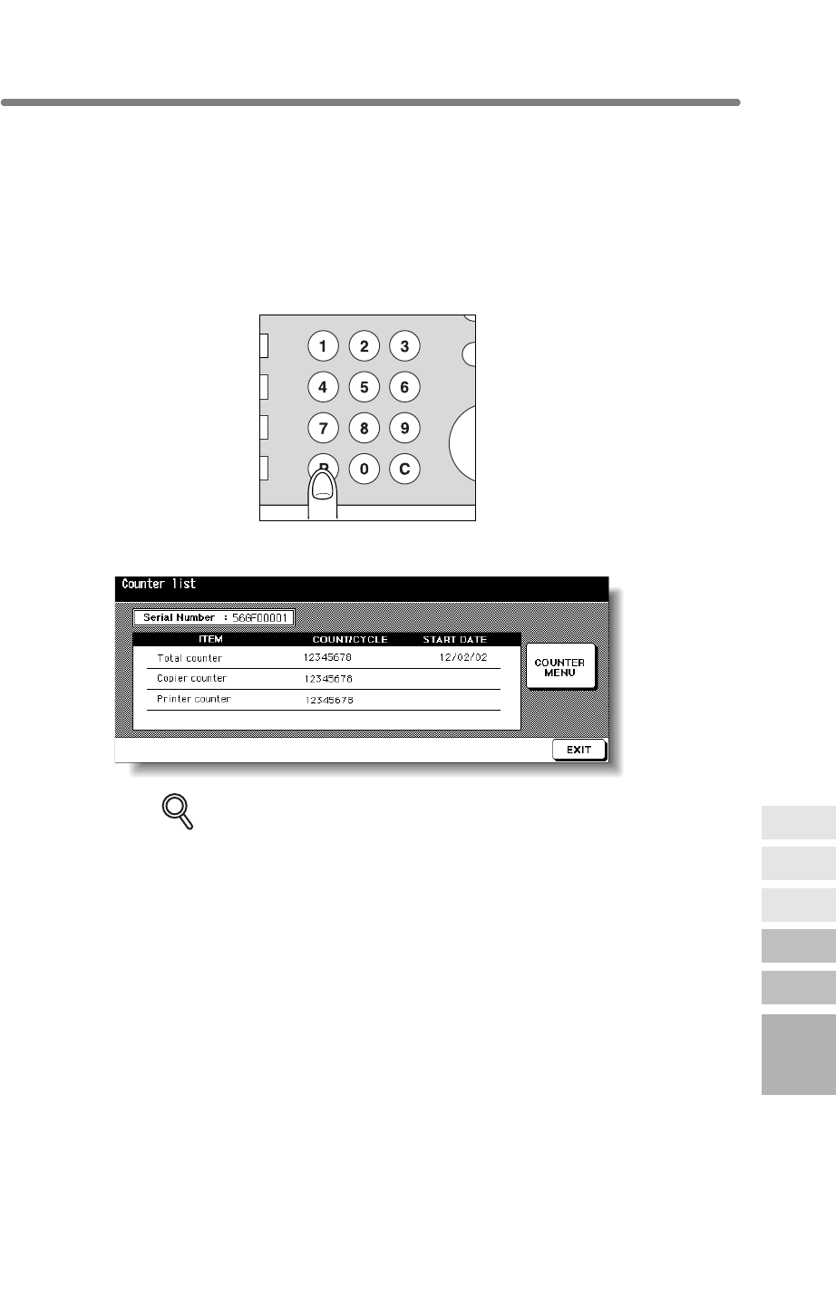
12-15
Checking Copy Count
This function allows you to view the current indication of the following items as a list on
Check the list, then print it from the Counter List Screen, if desired.
To Display the Counter List Screen
1. Press [P (COUNTER)] on the control panel.
The Counter List Screen will be displayed.
DETAILS
The Counter List Screen can be displayed even if printing job is in progress.
2. Touch EXIT to return to the Basic Screen.
R
IN
T
PR
O
S
Y
CLEAR QTY.
COUNTER
P
12
Maintenance
& Supplies
Checking
Copy Count
Cleaning
Scanning
Section
Empty Trash
Basket
Inserting New
Staple Cartridge
Adding Toner
the touch panel: Total counter, mfp counter, Printer counter, Counter start date.
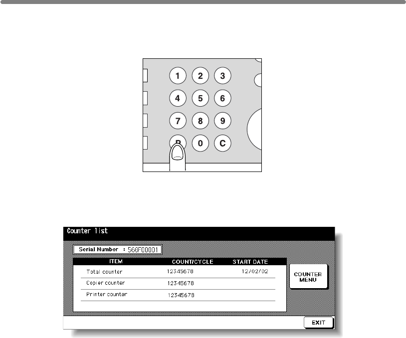
Checking Copy Count (continued)
12-16
To Print the Counter List
1. Press [P (COUNTER)] on the control panel.
The Counter List Screen will be displayed.
2. Touch COUNTER MENU.
The Basic Screen will be displayed.
3. Touch the desired tray key to select the copy size.
4. Press [START].
The Counter list will be printed out, and the Management list mode will be released
automatically.
R
IN
T
PR
O
S
Y
CLEAR QTY.
COUNTER
P

13
Machine Settings
How to Access the Key Operator Mode ..................................................13-2
[1] System Initial Setting ....................................................................13-4
13
Key Operator
Mode
Non-Image
Area Erase
Scan
Transmission
Adjustment
Timing
Adjustment
HDD
Management
Finisher
Adjustment
Side 2 Lens
Adjustment
Call Remote
Centre
Machine
Management
List Print
Memory
Switch
Power Save
Setting
Tray Auto
Select Setting
Control Panel
Adjustment
Weekly
Timer
Key Operator
Data Setting
Panel Contrast/
Key Sound
Paper Type/
Special Size
Lock/Delete
Job Memory
User Setting
Mode
Setting
System Initial
Setting
Key Operator
Mode
Key Operator Mode
Centering
E.C.M.
[3] User Setting Mode......................................................................13-10
[4] E.C.M. (Electronic Key Counter) Function Setting........................13-13
[5] Lock / Delete Job Memory .........................................................13-20
[6] Paper Type / Special Size Set ........................................................13-21
[7] Panel Contrast / Key Sound Adjustment ....................................13-23
[8] Key Operator Data Setting .............................................................13-24
[9] Weekly Timer .............................................................................13-25
[10] Control Panel Adjustment ............................................................13-34
[11] Tray Auto Select Setting ..........................................................13-35
[12] Power Save Setting......................................................................13-36
[13] Memory Switch Setting............................................................13-37
[14] Machine Management List Print ..................................................13-43
[15] Call Remote Centre .................................................................13-44
[16] Side 2 Lens Adjustment ...............................................................13-45
[17] Finisher Adjustment .................................................................13-46
[18] HDD Management Setting ...........................................................13-48
[19] Scan Transmission Setting ......................................................13-50
[20] Non-Image Area Erase Setting ....................................................13-52
[21] Timing Adjustment ...................................................................13-53
[22] Centering Adjustment...................................................................13-55
How to Monitor mfp Activity and Modify
mfp Initial
[2] mfp Initial Setting ...............................................................................13-8
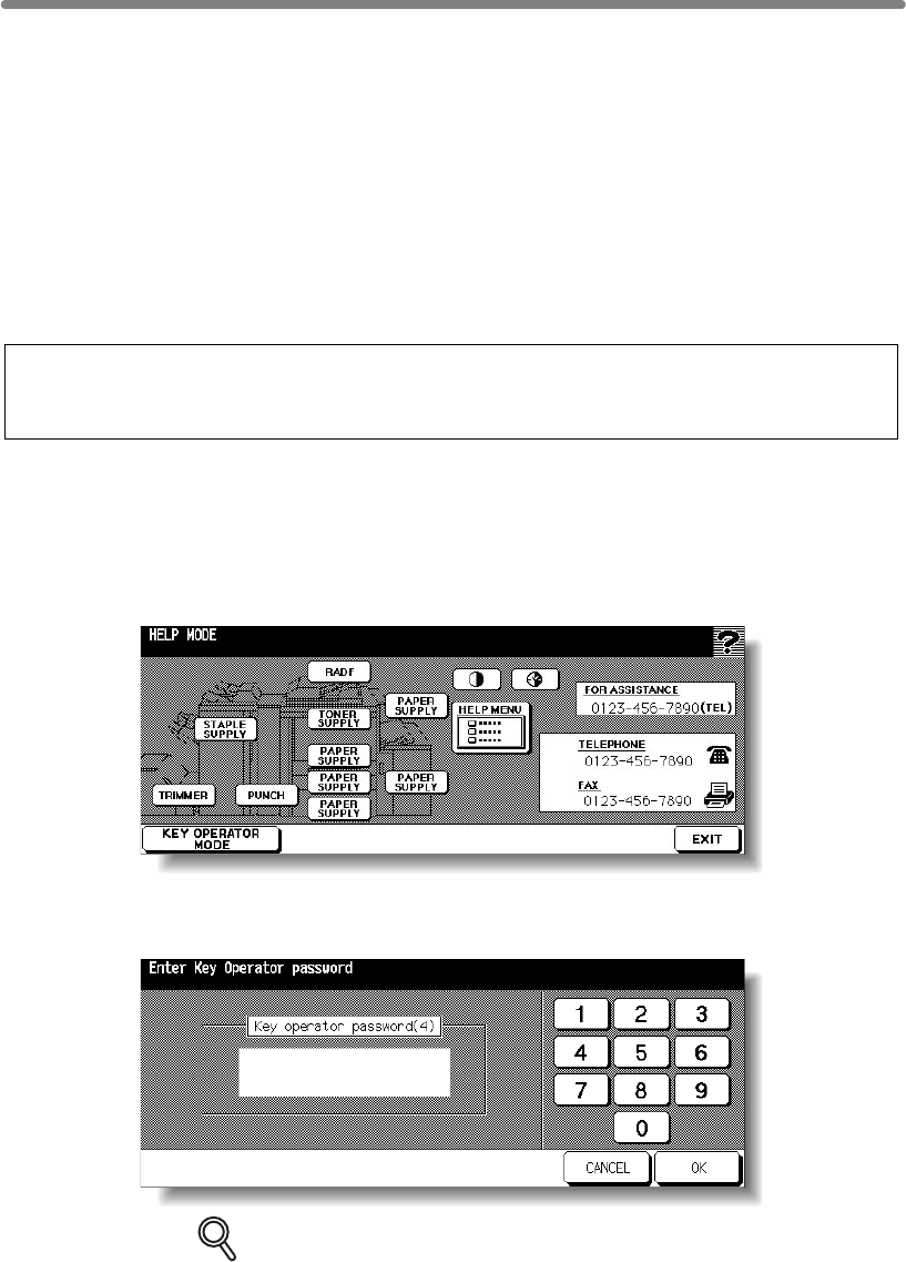
13-2
How to Access the Key Operator Mode
The Key Operator is trained to handle all special Key Operator functions that are not
performance, and service information, modifying machine settings, and controlling user
activity, for billing purposes.
A unique 4-digit Key Operator password is normally set by service at installation. If the
Entry Screen when the Key Operator mode is being accessed, and a Key Operator
password will not be required. A service-set 8-digit ECM master key code must be
entered by the Key Operator to access the Electronic Key Counter functions, and a
service-set 4-digit Weekly Timer master key code must be entered by the Key Operator
to access the Weekly Timer functions.
To ensure the security of Key Operator mode, it is recommended that you establish a
unique Key Operator password, along with the Key Operator ECM master key code
and Weekly Timer master key code, and keep them in a confidential file.
To Display the Key Operator Mode Screen
1. Press [HELP] on the control panel to display the Help Screen.
2. Touch KEY OPERATOR MODE on the Help Screen.
3. Use the keypad on the touch screen to enter your 4-digit Key Operator
password; then touch OK.
DETAILS
If an invalid Key Operator password is entered, continue by entering the
valid 4-digit password.
If the Key Operator password is not valid, check with your service represen-
tative.
accessible to the general user, such as monitoring overall mfp activity, machine
unique code is not set by service, the mfp will not display Key Operator Password
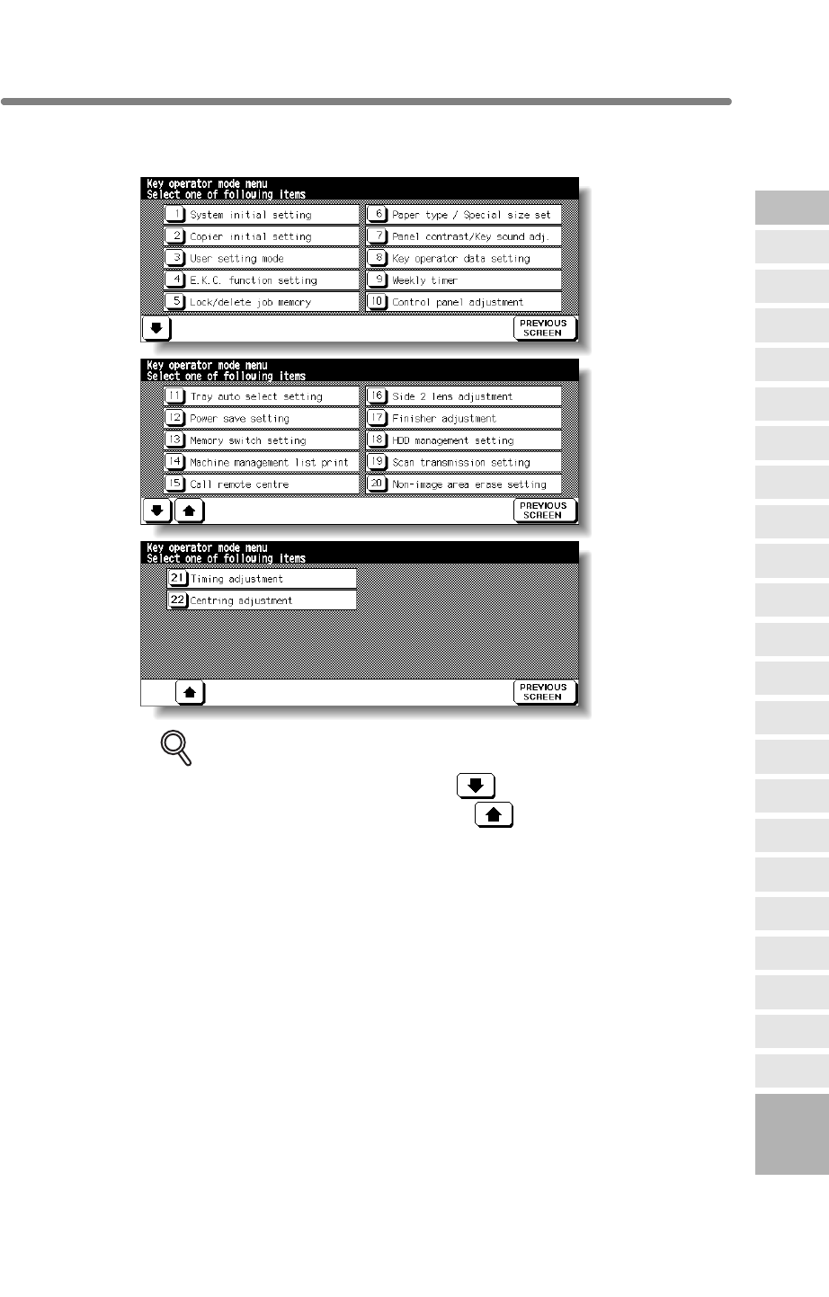
How to Access the Key Operator Mode (continued)
13-3
4. Make setting changes from the Key Operator Mode Screen, as
described on the following pages.
DETAILS
• To scroll to menus [11] to [22], touch .
To return to the previous screen, touch .
• The function number [15] Call remote centre on the Key Operator Mode
remote diagnostics activated.
5. Touch PREVIOUS SCREEN to exit the Key Operator mode.
The Basic Screen will be restored.
13
Key Operator
Mode
Non-Image
Area Erase
Scan
Transmission
Adjustment
Timing
Adjustment
HDD
Management
Finisher
Adjustment
Side 2 Lens
Adjustment
Call Remote
Centre
Machine
Management
List Print
Memory
Switch
Power Save
Setting
Tray Auto
Select Setting
Control Panel
Adjustment
Weekly
Timer
Key Operator
Data Setting
Panel Contrast/
Key Sound
Paper Type/
Special Size
Lock/Delete
Job Memory
E.C.M.
User Setting
Mode
Setting
System Initial
Setting
Key Operator
Mode
Centering
mfp Initial
Screen will be dimmed and cannot be selected on the mfp without the
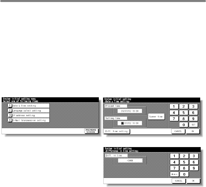
13-4
[1] System Initial Setting
• Date & Time setting: Current date and time, summer time
• Language select setting: Language used in LCD (English)
• IP address setting: IP address to be accessed from PC
• E-mail address setting: E-mail address to be informed of machine trouble or request
for supplies.
[1] Date & Time Setting
Set the current date and time, the summer time, and also the time difference.
❒Default setting: Summer time off
System Initial Setting Menu Screen Date & Time Setting Screen
Difference in Time Setting Screen
Procedure
1Touch [1] System initial setting on the Key Operator Mode Screen to display the
System Initial Setting Menu Screen.
2Touch [1] Date & Time setting to display the Date & Time Setting Screen.
3Adjust the time.
month, year, and time (in 24-hour expression).
(1) Touch SET to move the highlighted section to the number to be changed.
(2) Use the keypad on the screen to enter the number.
4To activate the summer time function, touch Summer time to highlight it. The Present
time will gain an hour.
5The Difference in time setting is provided in order to give the time difference information
at the same time when E-mail is received.
To set this function, follow the procedure below.
(1) Touch Diff. time setting to display the Difference in Time Setting Screen.
(2) Touch +– to display “+” when the local time is earlier than Universal time, or “–”
when the local time is later.
(3) Use the keypad on the screen to enter the time difference between Universal time
and the local time in the machine setting area.
(e.g. Enter “–0900” for 9 hours later than Universal time.)
Set the following initial conditions of the mfp.
The time that the mfp currently has is displayed in the upper line, in the order of date,

[1] System Initial Setting (continued)
13-5
6Touch OK to update the Present time by the Setting time and return to the System Initial
Setting Menu Screen.
7Touch PREVIOUS SCREEN to restore the Key Operator Mode Screen.
8If no further changes are required, touch PREVIOUS SCREEN to restore the Basic
Screen to perform copying operations.
13
Key Operator
Mode
Non-Image
Area Erase
Scan
Transmission
Adjustment
Timing
Adjustment
HDD
Management
Finisher
Adjustment
Side 2 Lens
Adjustment
Call Remote
Centre
Machine
Management
List Print
Memory
Switch
Power Save
Setting
Tray Auto
Select Setting
Control Panel
Adjustment
Weekly
Timer
Key Operator
Data Setting
Panel Contrast/
Key Sound
Paper Type/
Special Size
Lock/Delete
Job Memory
E.C.M.
User Setting
Mode
Setting
System Initial
Setting
Key Operator
Mode
Centering
mfp Initial
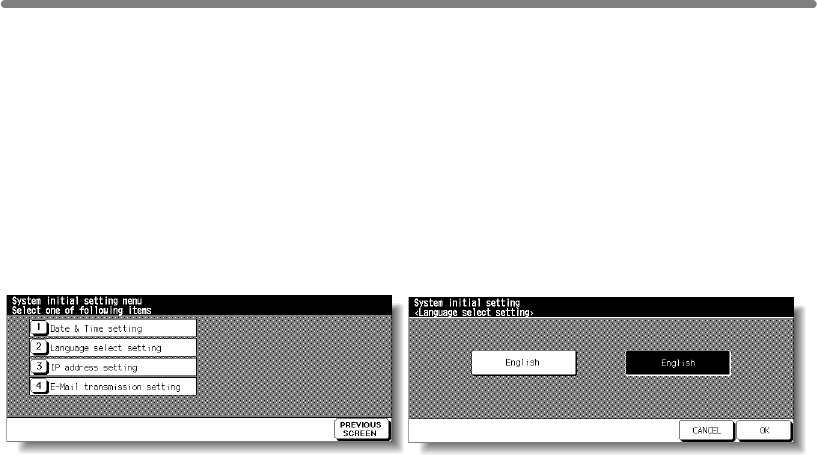
[1] System Initial Setting (continued)
13-6
[2] Language Select Setting
❒Default setting: English
System Initial Setting Menu Screen Language Selection Screen
Procedure
1Touch [1] System initial setting on the Key Operator Mode Screen to display the
System Initial Setting Menu Screen.
2Touch [2] Language select setting to display the Language Selection Screen.
3Select the desired language mode.
4Touch OK to complete the setting and return to the System Initial Setting Menu Screen.
5Touch PREVIOUS SCREEN to restore the Key Operator Mode Screen.
6If no further changes are required, touch PREVIOUS SCREEN to restore the Basic
Screen to perform copying operations.
on installation.
Note: Additional languages *French, Italian, German and Spanish) are available
Select the language used in the LCD.
upon request. Please contact your HP service representative for more details

[1] System Initial Setting (continued)
13
Key Operator
Mode
Non-Image
Area Erase
Scan
Transmission
Adjustment
Timing
Adjustment
HDD
Management
Finisher
Adjustment
Side 2 Lens
Adjustment
Call Remote
Centre
Machine
Management
List Print
Memory
Switch
Power Save
Setting
Tray Auto
Select Setting
Control Panel
Adjustment
Weekly
Timer
Key Operator
Data Setting
Panel Contrast/
Key Sound
Paper Type/
Special Size
Lock/Delete
Job Memory
E.C.M.
User Setting
Mode
Setting
System Initial
Setting
Key Operator
Mode
Centering
[3] IP Address Setting
Consult your EFI Print Controller documentation.
[4] E-Mail Transmission Setting
Consult your EFI Print Controller documentation.
13-7
mfp Initial
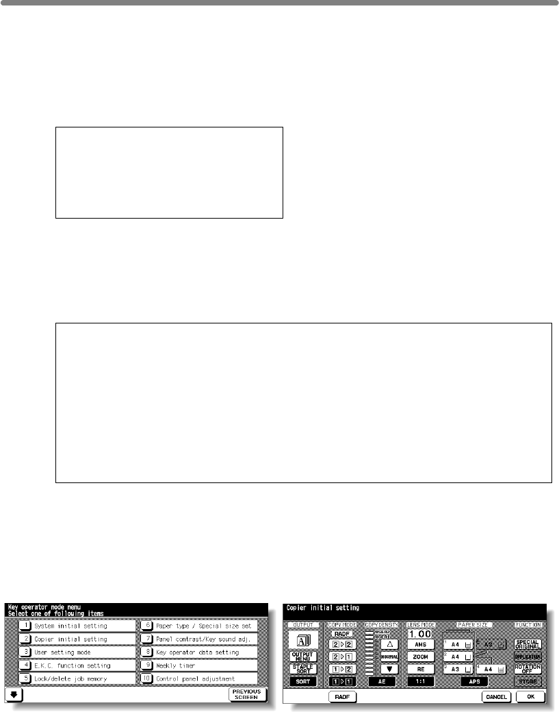
when Auto/Reset timer is operated, or when [AUTO RESET] key is pressed. These
settings can be changed by the Key Operator, as shown in this section.
Initially (i.e., at installation), the Basic Screen displays the following conditions to meet
Energy Star requirements:
Initial Setting
Copy Mode : 1-1
Copy Density : AE
Lens Mode : 1:1
Paper Tray : APS
Output Mode : offset sort
When Initial settings are changed by the Key Operator, the new initial settings display
RESET] key is pressed.
The following initial settings can be changed by the Key Operator:
Copy mode :
Copy density : [AE; manual]
Lens mode : [AMS; ratio 0.25~4.00]
Paper tray :
Output mode : [Non-sort; Sort, Group; Staple-sort; Stitch&Fold; Fold;
Punch; Trimming; Cover sheet]
Special original : [Original Direction; Text/Photo Enhance; Special Original;
Original Form]
Rotation : OFF
Setting procedures are described on the following pages.
NOTE:
The most commonly-used settings are established at installation. Before
and long-range effect of the change.
Key Operator Mode Screen
[RADF; 1-1; 1-2; 2-2; 2-1]
[APS; trays 1, 2, 3, HCI or optional tray 4]
13-8
[2] mfp Initial Setting
Initial settings are the settings that display automatically when the mfp is powered on,
changing any of the mfp settings, be sure that you understand the overall
when the mfp is powered on, when Auto/Reset timer is reached, or when [AUTO
mfp Initial Setting Screen

Procedure
1
Initial Setting Screen.
2Make a selection for each mode as initial settings.
NOTE:
The machine will restore the initial settings specified as above unless the
Memory switch No. 4 “JOB memory (30) auto recall” is turned ON with the
Job memory No. 30 registered.
3Touch OK to complete the setting and return to the Key Operator Mode Screen.
4If no further changes are required, touch PREVIOUS SCREEN to restore the Basic
Screen to perform copying operations.
13
Key Operator
Mode
Non-Image
Area Erase
Scan
Transmission
Adjustment
Timing
Adjustment
HDD
Management
Finisher
Adjustment
Side 2 Lens
Adjustment
Call Remote
Centre
Machine
Management
List Print
Memory
Switch
Power Save
Setting
Tray Auto
Select Setting
Control Panel
Adjustment
Weekly
Timer
Key Operator
Data Setting
Panel Contrast/
Key Sound
Paper Type/
Special Size
Lock/Delete
Job Memory
E.C.M.
User Setting
Mode
Setting
System Initial
Setting
Key Operator
Mode
Touch RADF to select or deselect it.
Centering
13-9
[2] mfp Initial Setting (continued)
mfp Initial
Touch [2] mfp Initial setting on the Key Operator Mode Screen to display the mfp
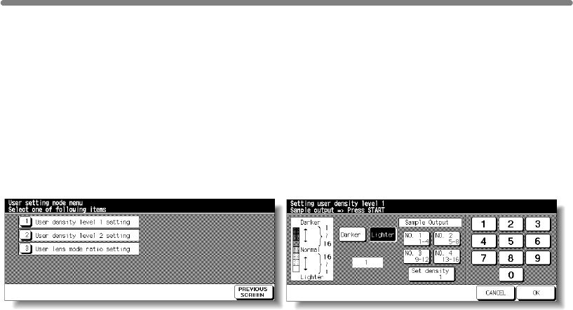
[3] User Setting Mode
Set two userset density levels and three USERSETs of magnification.
[1] User Density Level 1 Setting
Output copying samples from 16 density levels from Lighter to Normal or Normal to
Darker, then select the desired exposure and program it as USER1.
The programmed copy density can be recalled by selecting USER1 on the Basic
Screen.
User Setting Mode Menu Screen User Density Level 1 Setting Screen
Procedure
1Touch [3] User setting mode on the Key Operator Mode Screen to display the User
Setting Mode Menu Screen.
2Touch [1] User density level 1 setting to display the User Density Level 1 Setting
Screen.
3
4Touch Darker or Lighter to select the density level to be programmed.
5Touch No.1 1~4, No.2 5~8, No.3 9~12, No.4 13~16, or Set density ##, then press
[START]. The density level sample sheet will be output.
6Select the desired exposure from the sample sheet(s), then enter the density level No.
by using the touch screen keypad.
7Touch OK to complete the setting and return to the User Setting Mode Menu Screen.
8Touch PREVIOUS SCREEN to restore the Key Operator Mode Screen.
9If no further changes are required, touch PREVIOUS SCREEN to restore the Basic
Screen to perform copying operations.
Place the original on the platen glass or in the RADF.
13-10
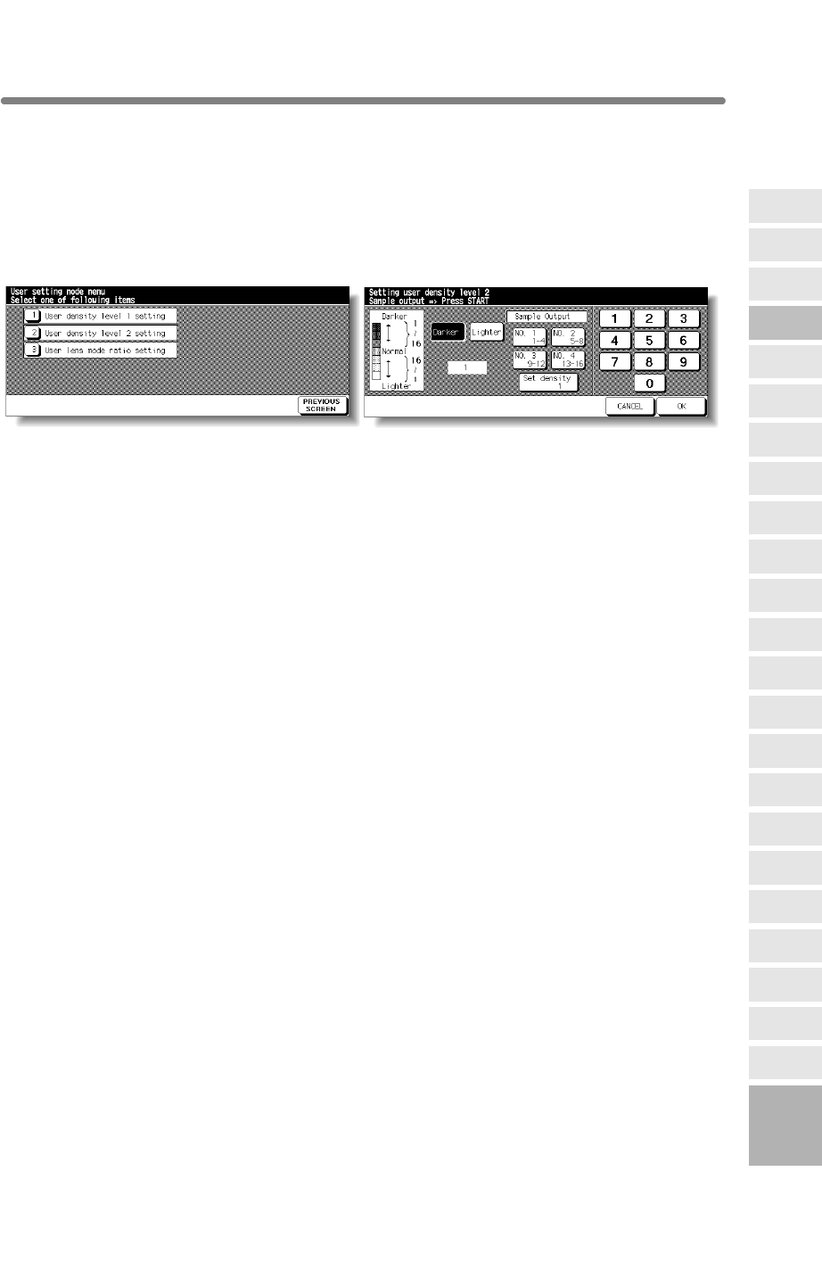
[3] User Setting Mode (continued)
[2] User Density Level 2 Setting
Output copying samples from 16 density levels from Lighter to Normal or Normal to
Darker, then select the desired exposure and program it as USER2.
The programmed copy density can be recalled by selecting USER2 on the Basic
Screen.
User Setting Mode Menu Screen User Density Level 2 Setting Screen
Procedure
1Touch [3] User setting mode on the Key Operator Mode Screen to display the User
Setting Mode Menu Screen.
2Touch [2] User density level 2 setting to display the User Density Level 2 Setting
Screen.
3Place the original on the platen glass.
4Touch Darker or Lighter to select the density level to be programmed.
5Touch No.1 1~4, No.2 5~8, No.3 9~12, No.4 13~16, or Set density ##, then press
[START]. The density level sample sheet will be output.
6Select the desired exposure from the sample sheet(s), then enter the density level No.
by using the touch screen keypad.
7Touch OK to complete the setting and return to the User Setting Mode Menu Screen.
8Touch PREVIOUS SCREEN to restore the Key Operator Mode Screen.
9If no further changes are required, touch PREVIOUS SCREEN to restore the Basic
Screen to perform copying operations.
13
Key Operator
Mode
Non-Image
Area Erase
Scan
Transmission
Adjustment
Timing
Adjustment
HDD
Management
Finisher
Adjustment
Side 2 Lens
Adjustment
Call Remote
Centre
Machine
Management
List Print
Memory
Switch
Power Save
Setting
Tray Auto
Select Setting
Control Panel
Adjustment
Weekly
Timer
Key Operator
Data Setting
Panel Contrast/
Key Sound
Paper Type/
Special Size
Lock/Delete
Job Memory
E.C.M.
User Setting
Mode
Setting
System Initial
Setting
Key Operator
Mode
Centering
13-11
mfp Initial
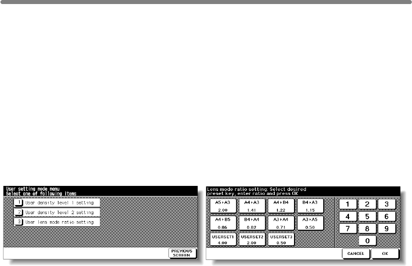
[3] User Setting Mode (continued)
[3] User Lens Mode Ratio Setting
The preset and userset ratios are used to reduce and enlarge the original image to
accommodate copy paper size, and are available on the Basic Screen.
NOTE:
Normally, users are allowed to change the three USERSETs in the bottom
line on the User Lens Mode Ratio Setting Screen. The preset keys in the top
and middle lines can also be programmed in 2-5 DIPSW mode; however,
changing them is not recommended.
❒Setting options:Userset or Preset ratio
❒Default setting: USERSET1: 4.00
USERSET2: 2.00
USERSET3: 0.50
User Setting Mode Menu Screen User Lens Mode Ratio Setting Screen
Procedure
1Touch [3] User setting mode on the Key Operator Mode Screen to display the User
Setting Mode Menu Screen.
2Touch [3] User lens mode ratio setting to display the User Lens Mode Ratio Setting
Screen.
3Touch the USERSET you want to change, then enter a ratio from 0.25~4.00, using the
keypad.
If a ratio under 0.25 is entered, 0.25 will be displayed.
If a ratio over 4.00 is entered, 4.00 will be displayed.
4Touch OK to complete the setting and return to the User Setting Mode Menu Screen.
5Touch PREVIOUS SCREEN to restore the Key Operator Mode Screen.
6If no further changes are required, touch PREVIOUS SCREEN to restore the Basic
Screen to perform copying operations.
13-12

[4] E.C.M. (Electronic Key Counter) Function Setting
This function can only be accessed by the Key Operator after a 8-digit ECM master key
code is entered. The Electronic Key Counter allows you to monitor all copying activity
by controlling ECM password accounts.
also be set. Use the ECM Key Operator Form provided at the end of this section to
record ECM password information.
The ECM stores up to 1,000 ECM passwords, each of which represents a separate
to each account may depend upon the billing system in operation and the number of
be performed only after a valid ECM password is entered.
Copy quantity and copy limit for each account can be visually confirmed on the screen.
If ECM needs to be activated on your machine, contact your service representative.
The following ECM settings can be made:
[1] E.C.M. data edit:
Change, add, or delete ECM data, and reset the copy count of the individual account.
[2] E.C.M. all count reset:
Clear the copy count for all accounts.
[3] E.C.M. function setting:
Select the ECM function to be on or off, and also set the machine condition when the
copy limit is reached to stop immediately or after a job is completed, or to only display a
warning message.
13
Key Operator
Mode
Non-Image
Area Erase
Scan
Transmission
Adjustment
Timing
Adjustment
HDD
Management
Finisher
Adjustment
Side 2 Lens
Adjustment
Call Remote
Centre
Machine
Management
List Print
Memory
Switch
Power Save
Setting
Tray Auto
Select Setting
Control Panel
Adjustment
Weekly
Timer
Key Operator
Data Setting
Panel Contrast/
Key Sound
Paper Type/
Special Size
Lock/Delete
Job Memory
E.C.M.
User Setting
Mode
Setting
System Initial
Setting
Key Operator
Mode
Centering
account that can be used for billing and record keeping. The number of users assigned
13-13
mfp Initial
This feature can track mfp usage for individual users and/or accounts as well as limit
access to the mfp to authorized users. Copy quantity limits for specific accounts can
individuals and departments using the mfp. When the ECM is activated, copying can
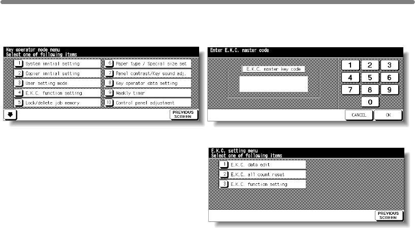
[4] E.C.M. (Electronic Key Counter) Function Setting (continued)
How to Access the ECM Setting Mode
Key Operator Mode Screen ECM Master Key Code Screen
ECM Setting Menu Screen
Procedure
1 Touch [4] E.C.M. function setting on the Key Operator Mode Screen. The ECM Master
Key Code Screen displays, if a code is required.
2 Use the keypad on the touch screen to enter your 8-digit ECM master key code, then
touch OK to display the ECM Setting Menu Screen. (See note.)
3 Select the desired ECM function, and make settings, as required.
To exit the ECM mode, touch PREVIOUS SCREEN on the ECM Setting Menu Screen.
4To exit the Key Operator mode, touch PREVIOUS SCREEN on the Key Operator Mode
Screen to restore the Basic Screen.
NOTE:
If an invalid ECM master key code is entered, continue by entering the valid
8-digit code. The ECM master key code can be set to less than 8 digits by
the Memory switch setting of the Key Operator function.
13-14
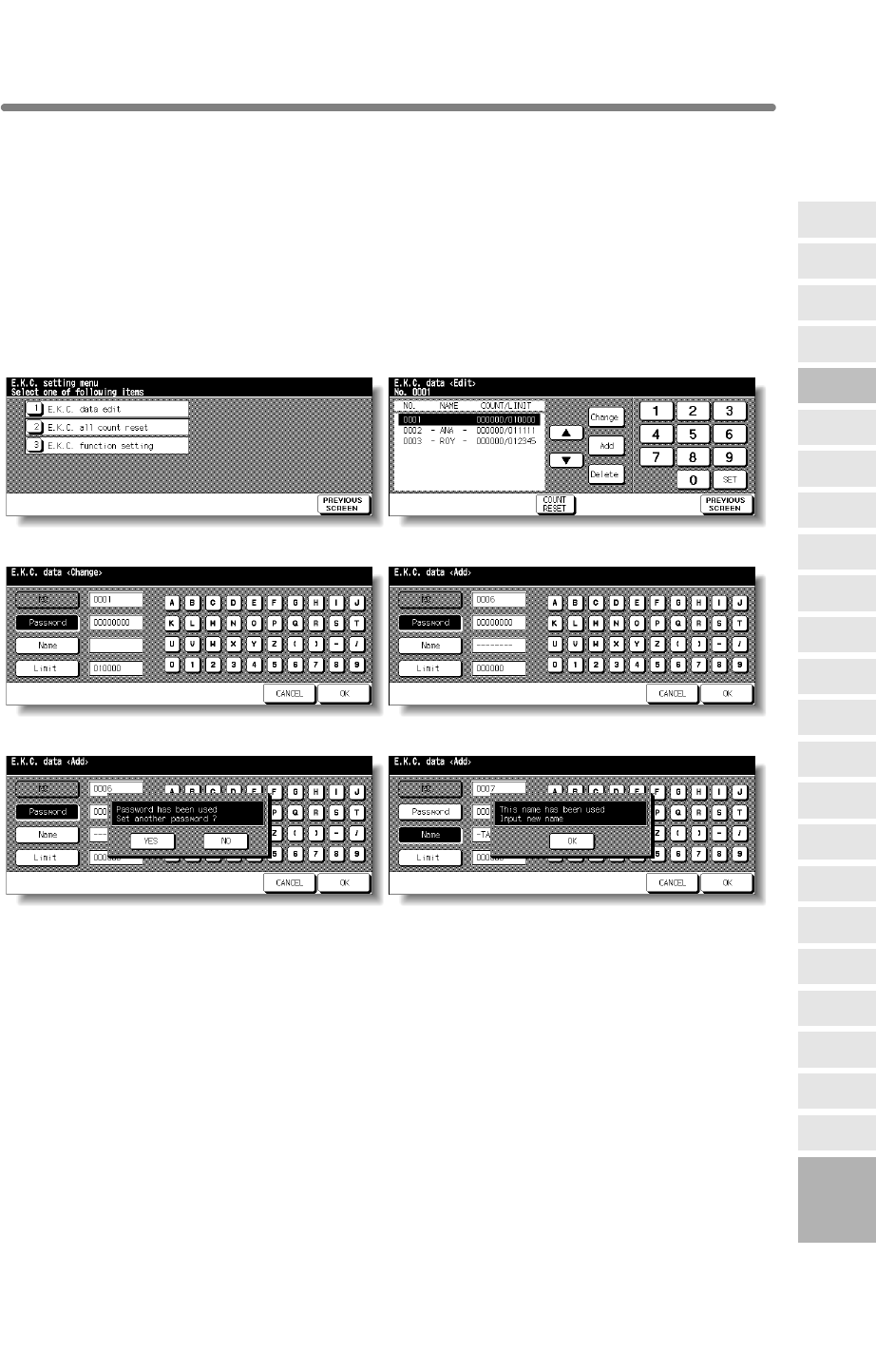
[4] E.C.M. (Electronic Key Counter) Function Setting (continued)
[1] E.C.M. Data Edit
Use this setting to display the list of copy count and copy limit for each account, to
change, add, or delete the ECM data, and to reset the copy count of the individual
account.
❒ ECM No.: Designated by Key Operator
❒ ECM Password: Unique 8-digit numeric code programmed by Key Operator for user
❒User Name: Max. 8 characters
❒ Copy Limit: 0 to 999,999 copies
Password Duplication Screen Name Duplication Screen
Procedure
1 Touch [4] E.C.M. function setting on the Key Operator Mode Screen. Enter an 8-digit
NOTE:
If an invalid ECM master key code is entered, continue by entering the valid
8-digit code.
2 Touch [1] E.C.M. data edit. The ECM Data Edit Screen will be displayed.
13
Key Operator
Mode
Non-Image
Area Erase
Scan
Transmission
Adjustment
Timing
Adjustment
HDD
Management
Finisher
Adjustment
Side 2 Lens
Adjustment
Call Remote
Centre
Machine
Management
List Print
Memory
Switch
Power Save
Setting
Tray Auto
Select Setting
Control Panel
Adjustment
Weekly
Timer
Key Operator
Data Setting
Panel Contrast/
Key Sound
Paper Type/
Special Size
Lock/Delete
Job Memory
E.C.M.
User Setting
Mode
Setting
System Initial
Setting
Key Operator
Mode
Centering
ECM Setting Menu Screen ECM Data Edit Screen
ECM Data Change Screen ECM Data Add Screen
ECM master key code, then touch OK to display the ECM Setting Menu Screen.
13-15
mfp Initial

[4] E.C.M. (Electronic Key Counter) Function Setting (continued)
3 To change, add, or delete the ECM data, and to reset the copy count of the individual
account, follow the procedure for each as described below.
To Change ECM Data:
changed, then touch Change. The ECM Data Change Screen will be displayed.
(2) Touch the desired item key to highlight it, then enter new data by using the touch
screen keypad.
Password: 8 digits max. (See note 1.)
Name: 8 characters max. (See note 2.)
Limit: 999,999 copies max.
NOTES:
1 We recommend that you make a list of all ECM passwords and account
numbers.
2 If an invalid user name is entered, continue by the valid name.
(3) Touch OK to complete the setting and to verify whether the same password or name
has been already used for another account No.
When a password is duplicated:
The Password Duplication Screen will be displayed. Touch YES to re-enter new
password, or NO to create duplicate password.
NOTE:
If duplicate password is created, the number of copies will be counted only
The Name Duplication Screen will be displayed. Touch OK to re-enter new name.
displayed.
(2) Touch the desired item key to highlight it, then enter the data by using the touch
screen keypad.
Password: 8 digits max. (See note 1.)
Name: 8 characters max. (See note 2.)
Limit: 999,999 copies max.
NOTES:
1
numbers.
2 If an invalid user name is entered, continue by the valid name.
(3) Touch OK to complete the setting and to verify whether the same password or name
has been already used for another account No.
When a password is duplicated:
The Password Duplication Screen will be displayed. Touch YES to re-enter new
password, or NO to create duplicate password.
NOTE:
If duplicate password is created, the number of copies will be counted only
The Name Duplication Screen will be displayed. Touch OK to re-enter new name.
(1) Touch p or q key on the right side of the list to highlight the ECM data to be
for the ECM password with the smallest No. We recommend you do not use
When a name is duplicated:
duplicate ECM password.
To Add ECM Data:
(1) Touch Add on the ECM Data Edit Screen. The ECM Data Add Screen will be
We recommend that you make a list of all ECM passwords and account
for the ECM password with the smallest No. We recommend you do not use
When a name is duplicated:
duplicate ECM password.
13-16
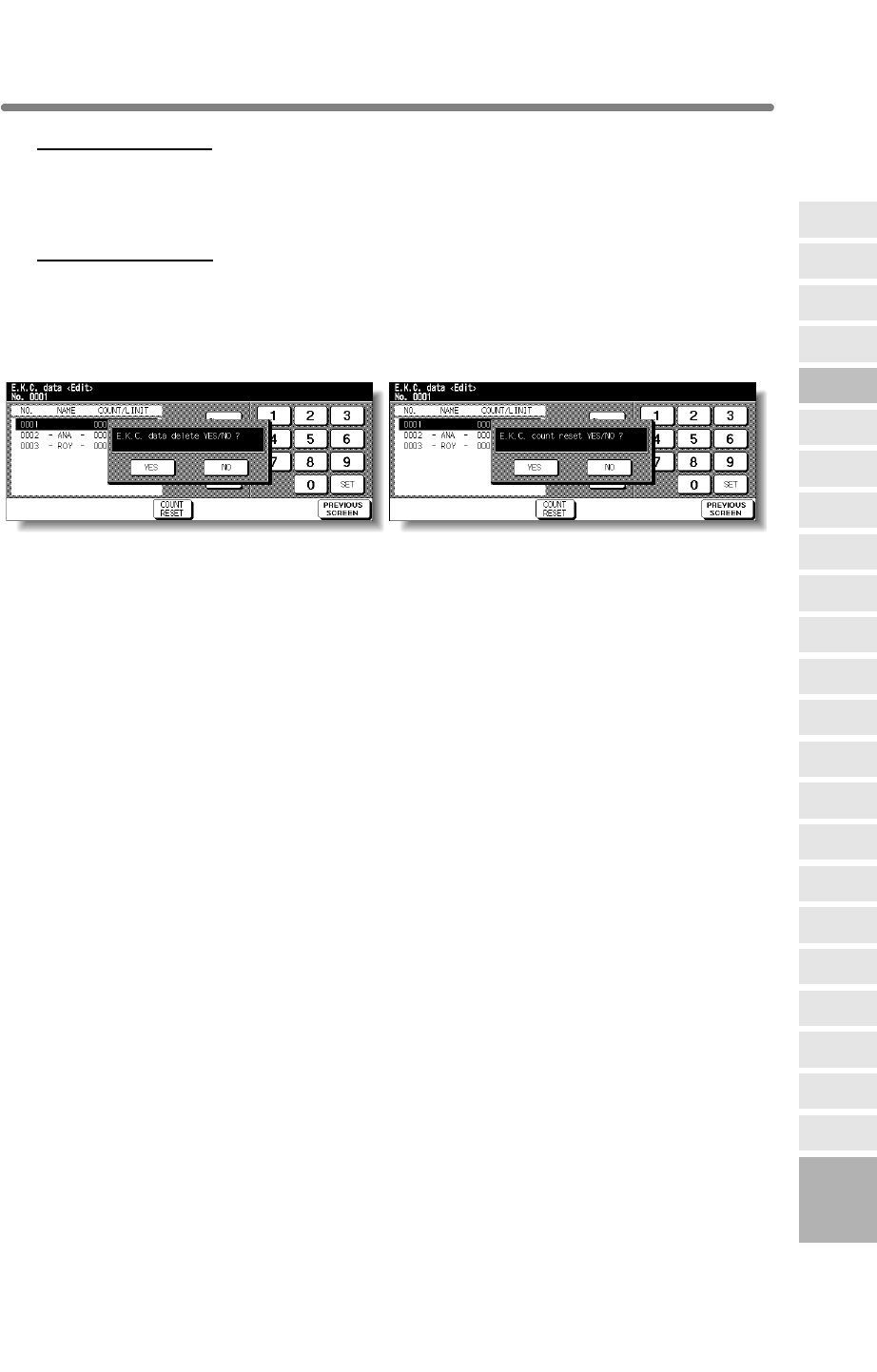
[4] E.C.M. (Electronic Key Counter) Function Setting (continued)
To Delete ECM Data:
then touch Delete. The Delete Confirmation Screen will be displayed.
(2) Touch YES to delete, or NO to cancel.
To Clear ECM Count:
touch COUNT RESET. The Reset Confirmation Screen will be displayed.
(2) Touch YES to clear the copy count of the selected ECM data, or NO to cancel.
Delete Confirmation Screen Reset Confirmation Screen
4 If other ECM setting changes are required, touch PREVIOUS SCREEN on the ECM
Data Edit Screen to return to the ECM Setting Menu Screen. Touch desired key, from
[1]~[3].
5Touch PREVIOUS SCREEN to restore the Key Operator Mode Screen.
6If no further changes are required, touch PREVIOUS SCREEN to restore the Basic
Screen to perform copying operations.
13
Key Operator
Mode
Non-Image
Area Erase
Scan
Transmission
Adjustment
Timing
Adjustment
HDD
Management
Finisher
Adjustment
Side 2 Lens
Adjustment
Call Remote
Centre
Machine
Management
List Print
Memory
Switch
Power Save
Setting
Tray Auto
Select Setting
Control Panel
Adjustment
Weekly
Timer
Key Operator
Data Setting
Panel Contrast/
Key Sound
Paper Type/
Special Size
Lock/Delete
Job Memory
E.C.M.
User Setting
Mode
Setting
System Initial
Setting
Key Operator
Mode
(1) Touch p or q key on the right side of the list to highlight the ECM data to be deleted,
(1) Touch p or q key on the right side of the list to highlight the desired ECM data, then
Centering
13-17
mfp Initial
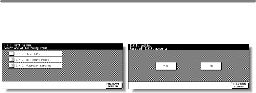
[4] E.C.M. (Electronic Key Counter) Function Setting (continued)
[2] E.C.M. All Count Reset
Reset the count for all ECM accounts.
ECM Setting Menu Screen ECM All Count Reset Screen
Procedure
1 Touch [4] E.C.M. function setting on the Key Operator Mode Screen. Enter an 8-digit
ECM master key code, then touch OK to display the ECM Setting Menu Screen.
NOTE:
If an invalid ECM master key code is entered, continue by entering the valid
8-digit code.
2 Touch [2] E.C.M. all count reset. The ECM All Count Reset Screen will be displayed.
3 Touch YES to reset all counters to zero and to return to the ECM Setting Menu Screen.
Or, touch NO to cancel. Touching PREVIOUS SCREEN will also cancel this function
and return to the ECM Setting Menu Screen.
4
5Touch PREVIOUS SCREEN to restore the Key Operator Mode Screen.
6If no further changes are required, touch PREVIOUS SCREEN to restore the Basic
Screen to perform copying operations.
If other ECM setting changes are required, touch desired key, from [1]~[3].
13-18

[4] E.C.M. (Electronic Key Counter) Function Setting (continued)
[3] E.C.M. Function Setting
Use this function to turn ECM On or Off, or to select whether the machine will stop when
when reaching maximum copy count.
ECM Setting Menu Screen ECM Function Setting Screen
Procedure
1 Touch [4] E.C.M. function setting on the Key Operator Mode Screen. Enter an 8-digit
ECM master key code, then touch OK to display the ECM Setting Menu Screen.
NOTE:
If an invalid ECM master key code is entered, continue by entering the valid
8-digit code.
2 Touch [3] E.C.M. function setting. The ECM Function Setting Screen will be displayed.
3 Touch ECM On to activate ECM or touch ECM Off to de-activate ECM.
The selected key will be highlighted.
4Touch Immediately to stop the machine at once when the copy limit is reached.
In this case, copy conditions selected for the current job will be cleared. To continue the
job using the same user password, change the copy limit of the password or clear the
copy count.
Touch After job to stop the machine after the current job is completed, when copy limit
is reached.
Touch Warning to only display a warning message when copy limit is reached.
The selected key will be highlighted.
5
6
7Touch PREVIOUS SCREEN to restore the Key Operator Mode Screen.
8If no further changes are required, touch PREVIOUS SCREEN to restore the Basic
Screen to perform copying operations.
13
Key Operator
Mode
Non-Image
Area Erase
Scan
Transmission
Adjustment
Timing
Adjustment
HDD
Management
Finisher
Adjustment
Side 2 Lens
Adjustment
Call Remote
Centre
Machine
Management
List Print
Memory
Switch
Power Save
Setting
Tray Auto
Select Setting
Control Panel
Adjustment
Weekly
Timer
Key Operator
Data Setting
Panel Contrast/
Key Sound
Paper Type/
Special Size
Lock/Delete
Job Memory
E.C.M.
User Setting
Mode
Setting
System Initial
Setting
Key Operator
Mode
Centering
Touch OK to complete the setting and return to the ECM Setting Menu Screen.
If other ECM setting changes are required, touch desired key, from [1]~[3].
13-19
mfp Initial
the count limit is reached, or if the mfp will complete the copy job before stopping
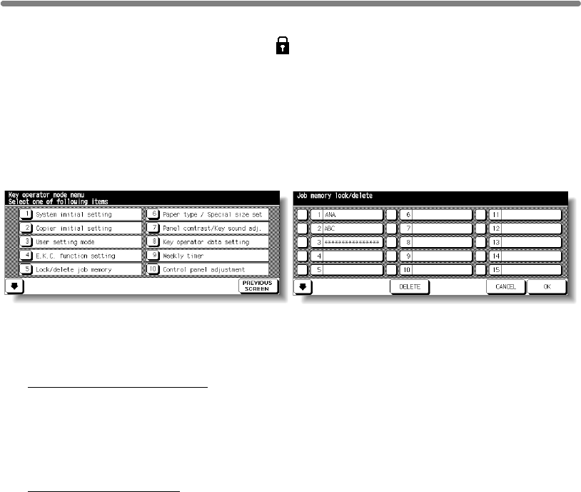
[5] Lock/Delete Job Memory
Use this function to lock/unlock or delete a Job that has been programmed.
A locked Job is indicated by a lock icon ( ) on the Lock/Delete Job Memory Screen.
The settings of a locked job cannot be changed.
❒Setting options: Lock Job memory, Unlock Job memory, Delete Job memory
❒Lock/delete is available for all 30 stored jobs
❒Job lock is available only for named jobs
❒A blank key indicates that no job is programmed
Key Operator Mode Screen Lock/Delete Job Memory Screen
Procedure
1Touch [5] Lock/delete job memory on the Key Operator Mode Screen to display the
Lock/Delete Job Memory Screen.
2To lock/unlock a job memory;
(1) Touch the key on the left side of the desired job number. Use arrow keys to scroll to
the desired job number, if required.
(2) The lock icon will appear on the touched key to show that the selected job is locked.
The previously locked job will be unlocked when selected, and the lock icon on the
touched key will disappear.
To delete a job memory;
(1) Touch the job number you want to delete. Use arrow keys to scroll to the desired job
number, if required.
(2) Touch DELETE. Selected programs and the name will be deleted from the job
memory.
3Touch OK to complete the setting and return to the Key Operator Mode Screen.
4If no further changes are required, touch PREVIOUS SCREEN to restore the Basic
Screen to perform copying operations.
❒∗∗∗∗∗∗∗∗∗∗∗∗∗∗∗∗ indicates that a job is programmed but unnamed
13-20
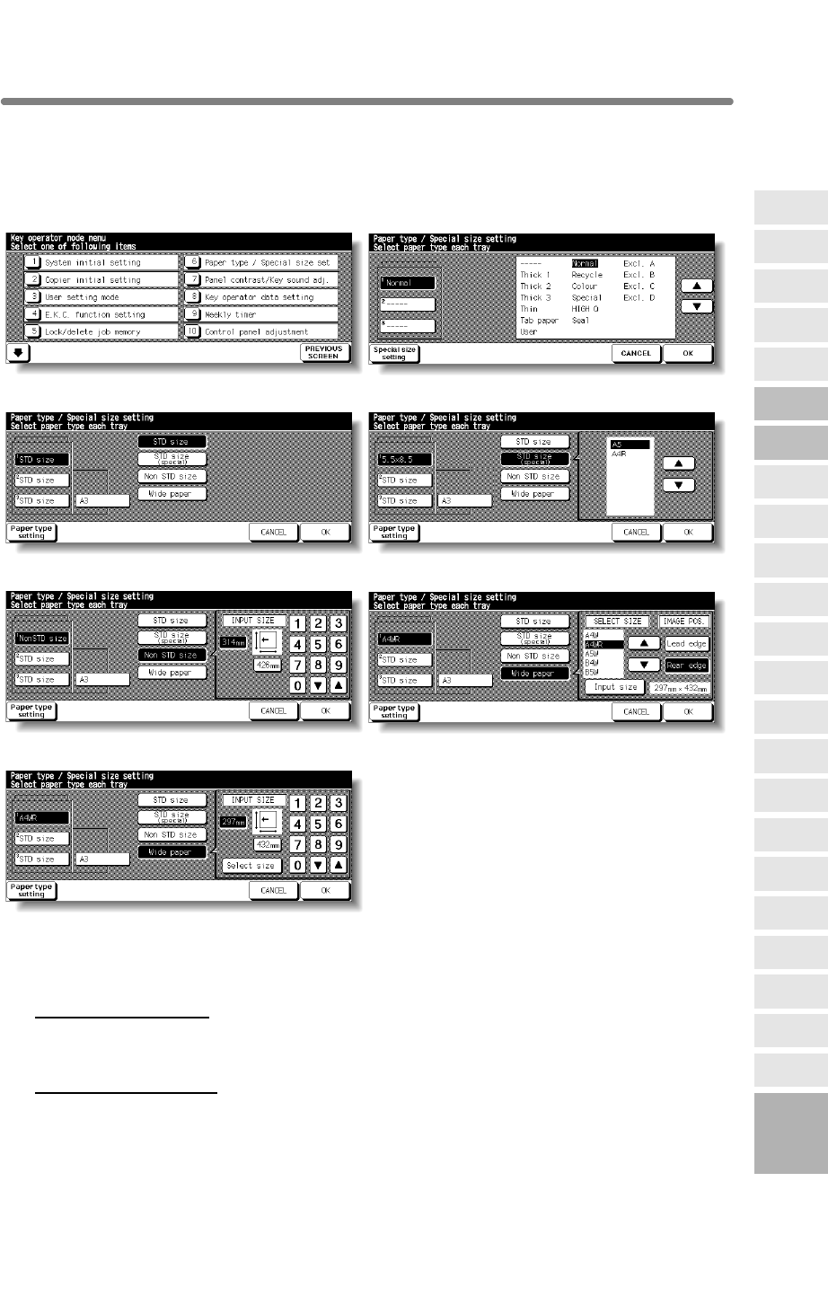
[6] Paper Type / Special Size Set
Use this function to indicate a specific paper type or to specify a special paper size for
each tray key on the Basic Screen. This is especially useful when special paper is used
on a regular basis and is always placed in a specific paper tray.
Key Operator Mode Screen Paper Type Setting Screen
Special Size Setting Screen (STD size)
Special Size Setting Screen (STD size (special))
Special Size Setting Screen (Non STD size) Special Size Setting Screen (Wide size (select))
Special Size Setting Screen (Wide size (input)
Procedure
1Touch [6] Paper type / Special size set on the Key Operator Mode Screen to display
the Paper Type Setting Screen.
2To specify paper type;
(1) Touch the desired paper tray key to highlight it.
(2) Touch the arrow keys to select paper type.
To specify special size;
(1) Touch Special size setting on the Paper Type Setting Screen to display the Special
Size Setting Screen.
(2) Touch the desired paper tray to highlight it.
(3) Touch a paper size key to specify a paper size for the selected tray.
13
Key Operator
Mode
Non-Image
Area Erase
Scan
Transmission
Adjustment
Timing
Adjustment
HDD
Management
Finisher
Adjustment
Side 2 Lens
Adjustment
Call Remote
Centre
Machine
Management
List Print
Memory
Switch
Power Save
Setting
Tray Auto
Select Setting
Control Panel
Adjustment
Weekly
Timer
Key Operator
Data Setting
Panel Contrast/
Key Sound
Paper Type/
Special Size
Lock/Delete
Job Memory
E.C.M.
User Setting
Mode
Setting
System Initial
Setting
Key Operator
Mode
Centering
13-21
mfp Initial

[6] Paper Type / Special Size Set (continued)
• Select STD size to allow the machine to automatically detect the size of paper
loaded in the tray and indicate it on the tray key.
• Select STD size (special) to display the popup menu to show available paper
sizes to be specified. Use arrow keys on the popup menu to select the desired
size.
• Select Non STD size to display the popup menu to enter the paper size by using
arrow keys or touch screen keypad.
• Select Wide size paper to display the popup menu to show available wide paper
sizes to be specified. Use arrow keys on the popup menu to select the desired
wide size, then touch Input size to display the popup menu to enter the paper size
by using arrow keys or touch screen keypad.
Touch Lead edge or Rear edge to select the image starting position.
3Touch OK on the Paper Type Setting Screen or on the Special Size Setting Screen to
complete the setting and return to the Key Operator Mode Screen.
4If no further changes are required, touch PREVIOUS SCREEN to restore the Basic
Screen to perform copying operations.
13-22
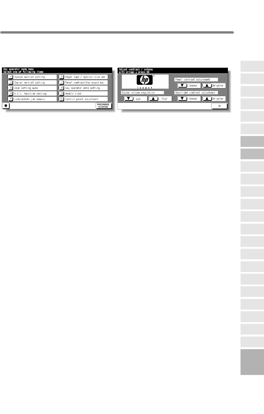
[7] Panel Contrast / Key Sound Adjustment
Use this feature to adjust the level of brightness of the touch screen portion of the
Key Operator Mode Screen
Panel Contrast/ Key Sound Adjustment Screen
Procedure
1Touch [7] Panel contrast/Key sound adj. on the Key Operator Mode Screen to display
the Panel Contrast/ Key Sound Adjustment Screen.
2Adjust the Panel contrast, Backlight contrast, or Buzzer volume, as desired.
Touch Dimmer to make the panel or backlight contrast dimmer than currently displayed,
or touch Brighter to make the panel or backlight contrast brighter than currently
displayed.
Touch Low or High to regulate the buzzer volume of the touch keys.
3Touch OK to complete the setting and return to the Key Operator Mode Screen.
4If no further changes are required, touch PREVIOUS SCREEN to restore the Basic
Screen to perform copying operations.
NOTE:
The control panel contrast feature can be adjusted from the Help screen.
When the Control panel contrast key is pressed, the Contrast adjustment
screen will be displayed.
13
Key Operator
Mode
Non-Image
Area Erase
Scan
Transmission
Adjustment
HDD
Management
Finisher
Adjustment
Side 2 Lens
Adjustment
Call Remote
Centre
Machine
Management
List Print
Memory
Switch
Power Save
Setting
Tray Auto
Select Setting
Control Panel
Adjustment
Weekly
Timer
Key Operator
Data Setting
Panel Contrast/
Key Sound
Paper Type/
Special Size
Lock/Delete
Job Memory
E.C.M.
User Setting
Mode
Setting
System Initial
Setting
Key Operator
Mode
Adjustment
Timing
Centering
13-23
control panel, and also the volume of the touch key sound.
mfp Initial
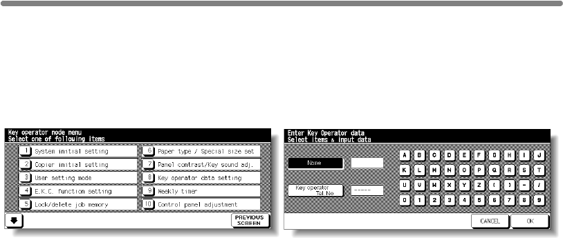
[8] Key Operator Data Setting
Use this screen to enter the name and extension number of the Key Operator indicated
on the Help Screen selected from the Basic Screen.
❒Setting options: 5-digit Key Operator telephone extension; Max. 8-character Key Operator
name
Key Operator Mode Screen Key Operator Data Setting Screen
Procedure
1Touch [8] Key operator data setting on the Key Operator Mode Screen to display the
Key Operator Data Setting Screen.
2Touch Name to highlight it, then enter the Key Operator name up to 8 characters from
the touch screen keypad.
3Touch Key Operator Tel. No. to highlight it, then enter a 5-digit extension number from
the touch screen keypad.
If the extension number is less than 5 digits, use a hyphen [-] to make it five. The hyphen
added in the beginning will be indicated as a space on the Help Screen.
4Touch OK to complete the setting and return to the Key Operator Mode Screen.
5If no further changes are required, touch PREVIOUS SCREEN to restore the Basic
Screen to perform copying operations.
13-24

[9] Weekly Timer
This function can be accessed only by the Key Operator after a unique 4-digit Weekly
Timer master key code is entered.
machine on a daily or hourly basis, and can be programmed specifically for lunch
In Addition, Timer Interrupt can be enabled (with or without a password requirement) to
allow temporary use of the machine during periods when power is shut down by the
Timer function.
Conditions required to use the Weekly Timer:
• The power plug is inserted into the socket.
• The power switch is turned on.
• The current date and time are correctly set.
If the Weekly Timer needs to be activated on your machine, contact your service repre-
sentative.
The following Weekly Timer settings can be made.
[1] Weekly timer ON/OFF setting
Enable and disable the Timer function.
[2] Timer Setting
the entire week.
[3] Timer action ON/OFF Setting
Specify the working days of the machine by the Timer, for all Mondays through
Sundays, and/or individually for each day of the given month.
[4] Lunch hour off setting
[5] Timer interrupt password set
Require Password entry for the Timer off function and establish the amount of
usage time.
NOTES:
1 The time is set in terms of the 24 hour clock, where hour [1] is the first
hour after midnight and hour [24] is the hour of midnight. For example, 6
a.m. is 06:00 hours; 6 p.m. is 18:00 hours.
2 The [AUTO RESET] key is used to change numbers determined by the
SET touch key.
13
Key Operator
Mode
Non-Image
Area Erase
Scan
Transmission
Adjustment
Timing
Adjustment
HDD
Management
Finisher
Adjustment
Side 2 Lens
Adjustment
Call Remote
Centre
Machine
Management
List Print
Memory
Switch
Power Save
Setting
Tray Auto
Select Setting
Control Panel
Adjustment
Weekly
Timer
Key Operator
Data Setting
Panel Contrast/
Key Sound
Paper Type/
Special Size
Lock/Delete
Job Memory
E.C.M.
User Setting
Mode
Setting
System Initial
Setting
Key Operator
Mode
Centering
13-25
mfp Initial
The Weekly Timer is a mfp management function that shuts down power to the
breaks, weekends and holidays, or any time the mfp is not required.
Specify the times that the mfp will turn ON and OFF for each day of the week or
Specify the lunch time interval during which the mfp will go off and on.
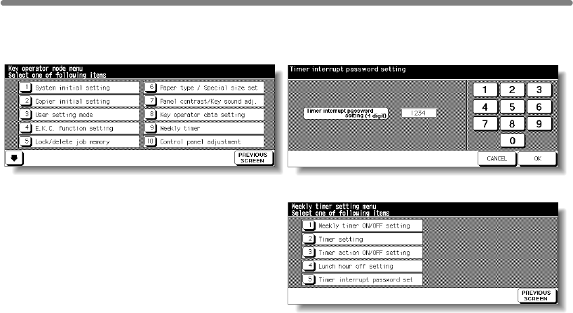
[9] Weekly Timer (continued)
How to Access the Weekly Timer Setting Mode
Key Operator Mode Screen Weekly Timer Master Key Code Screen
Weekly Timer Setting Menu Screen
Procedure
1Touch [9] Weekly timer on the Key Operator Mode Screen.
The Weekly Timer Master Key Code Screen displays when the 4-digit Weekly Timer
master key code is set by service.
Otherwise, the Weekly Timer Setting Menu Screen displays without the code
requirement.
2If the Weekly Timer Master Key Code Screen is displayed, use the keypad on the touch
screen to enter your 4-digit Weekly Timer master key code, then touch OK to display the
Weekly Timer Setting Menu Screen.
NOTE:
If an invalid Weekly Timer master key code is entered, continue by entering
the valid 4-digit code.
3Select the desired Weekly Timer function, and make settings, as required.
4To exit the Weekly Timer mode, touch PREVIOUS SCREEN on the Weekly Timer
Setting Menu Screen.
5To exit the Key Operator mode, touch PREVIOUS SCREEN on the Key Operator Mode
Screen to restore the Basic Screen.
13-26

[9] Weekly Timer (continued)
[1] Weekly Timer On/Off Setting
Weekly Timer Setting Menu Screen Weekly Timer On/Off Setting Screen
Procedure
1Touch [9] Weekly timer on the Key Operator Mode Screen.
Enter your 4-digit Weekly Timer master key code, then touch OK to display the Weekly
Timer Setting Menu Screen.
NOTE:
If an invalid Weekly Timer master key code is entered, continue by entering
the valid 4-digit code.
2Touch [1] Weekly timer ON/OFF setting to display the Weekly Timer On/Off Setting
Screen.
3Touch Weekly timer On to activate Weekly Timer, or touch Weekly timer Off to de-
activate Weekly Timer. The default setting is Weekly timer Off.
The selected key will be highlighted.
4Touch OK to complete the setting and return to the Weekly Timer Setting Menu Screen.
5Touch PREVIOUS SCREEN to restore the Key Operator Mode Screen.
6If no further changes are required, touch PREVIOUS SCREEN to restore the Basic
Screen to perform copying operations.
13
Key Operator
Mode
Non-Image
Area Erase
Scan
Transmission
Adjustment
Timing
Adjustment
HDD
Management
Finisher
Adjustment
Side 2 Lens
Adjustment
Call Remote
Centre
Machine
Management
List Print
Memory
Switch
Power Save
Setting
Tray Auto
Select Setting
Control Panel
Adjustment
Weekly
Timer
Key Operator
Data Setting
Panel Contrast/
Key Sound
Paper Type/
Special Size
Lock/Delete
Job Memory
E.C.M.
User Setting
Mode
Setting
System Initial
Setting
Key Operator
Mode
Centering
13-27
mfp Initial
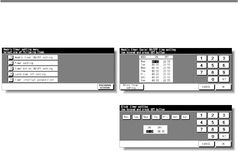
[9] Weekly Timer (continued)
[2] Timer Setting
Use this function to set the On/Off times in hours and minutes for each day of the week
or set the block time for the entire week, i.e., the same On/Off time for each day.
Weekly Timer Setting Menu Screen Weekly Timer On/Off Time Setting Screen
Weekly Timer On/Off Time Block Setting Screen
Procedure
1Touch [9] Weekly timer on the Key Operator Mode Screen.
Enter your 4-digit Weekly Timer master key code, then touch OK to display the Weekly
Timer Setting Menu Screen.
NOTE:
If an invalid Weekly Timer master key code is entered, continue by entering
the valid 4-digit code.
2Touch [2] Timer setting to display the Weekly Timer On/Off Time Setting Screen.
3When the screen is displayed, the ON-time of Monday is always highlighted.
Enter a 2-digit ON-hour (ex. 8 a.m. is 08) and a 2-digit ON-minute (ex. 7 min. is 07)
using the touch screen keypad, and then touch SET.
Touching SET repeatedly will shift the input section from Monday ON, Monday OFF,
Tuesday ON, Tuesday OFF etc.
NOTES:
• If ON-time and OFF-time are the same, power will not go on.
•
condition for specific days.
When setting Sunday OFF-time, Monday ON-time is highlighted again. Proceed to step
5.
4To set the ON/OFF time collectively for more than one day of the week, touch Block
timer setting to display the Weekly Timer On/Off Time Block Setting Screen.
5When you open this screen, the ON and OFF times are always set at 00:00~00:00.
Touch to highlight the day(s) of the week to be set. More than one can be selected at a
time.
Enter the ON-time and OFF-time using the touch screen keypad, and then touch SET
after each entry.
6Touch OK on the Weekly Timer On/Off Time Setting Screen or on the Weekly Timer On/
Off Time Block Setting Screen to complete the setting, and return to the Weekly Timer
Setting Menu Screen.
13-28
If the setting is 00:00~00:00, you will not be able to set the mfp off/on

[9] Weekly Timer (continued)
7Touch PREVIOUS SCREEN to restore the Key Operator Mode Screen.
8If no further changes are required, touch PREVIOUS SCREEN to restore the Basic
Screen to perform copying operations.
13
Key Operator
Mode
Non-Image
Area Erase
Scan
Transmission
Adjustment
Timing
Adjustment
HDD
Management
Finisher
Adjustment
Side 2 Lens
Adjustment
Call Remote
Centre
Machine
Management
List Print
Memory
Switch
Power Save
Setting
Tray Auto
Select Setting
Control Panel
Adjustment
Weekly
Timer
Key Operator
Data Setting
Panel Contrast/
Key Sound
Paper Type/
Special Size
Lock/Delete
Job Memory
E.C.M.
User Setting
Mode
Setting
System Initial
Setting
Key Operator
Mode
Centering
13-29
mfp Initial
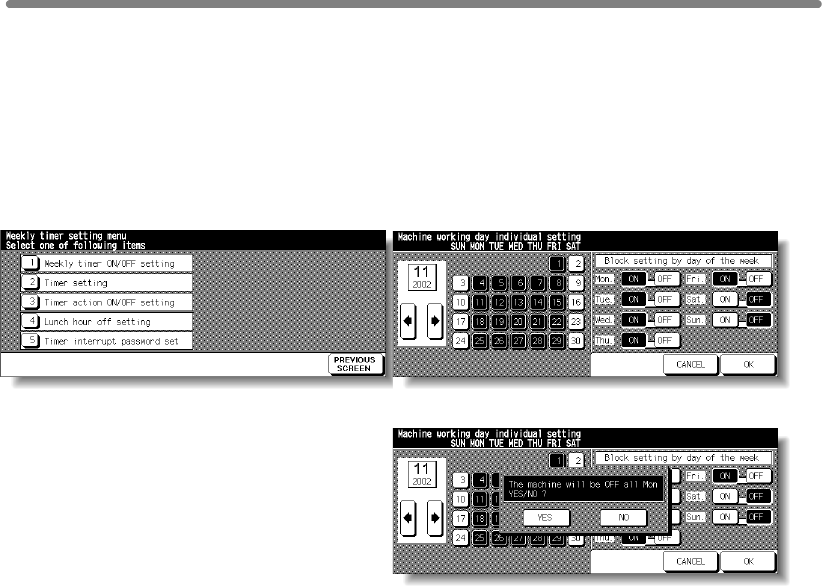
[9] Weekly Timer (continued)
[3] Timer Action On/Off Setting
Set the On-Off condition for specific days; or set it collectively, for all Mondays through
Sundays of the given month.
The default setting is collective: On for Mondays through Saturdays, and Off for
Sundays.
Weekly Timer Setting Menu Screen Timer Action On/Off Setting Screen
Timer Action Change Confirmation Screen
Procedure
1
Touch
[9] Weekly timer
on the Key Operator Mode Screen.
Enter your 4-digit Weekly Timer master key code, then touch
OK
to display the Weekly
Timer Setting Menu Screen.
NOTE:
If an invalid Weekly Timer master key code is entered, continue by entering
the valid 4-digit code.
2Touch [3] Timer action ON/OFF setting to display the Timer Action On/Off Setting
Screen.
The days of the current month are displayed on the left half of the screen, with timer-
active days highlighted.
3To activate or deactivate the Timer for any individual day, touch the key for that day to
change its indication.
To change the month, use arrows to scroll to the desired month.
4To collectively set the on/off data for the entire month by the day of the week, touch the
ON or OFF key for the desired day on the right half of the screen. If you touch an
already-highlighted key, no change will occur.
5If any change is made in the collective setting area, the Timer Action Change
Confirmation Screen will be displayed.
Touch YES to change the timer action, or touch NO to cancel.
The Timer Action On/Off Setting Screen will be restored.
6Touch OK on the Timer Action On/Off Setting Screen to complete the setting and
return to the Weekly Timer Setting Menu Screen.
13-30
Use this function to set the On/Off condition of the mfp for a given month.

[9] Weekly Timer (continued)
7Touch PREVIOUS SCREEN to restore the Key Operator Mode Screen.
8If no further changes are required, touch PREVIOUS SCREEN to restore the Basic
Screen to perform copying operations.
13
Key Operator
Mode
Non-Image
Area Erase
Scan
Transmission
Adjustment
Timing
Adjustment
HDD
Management
Finisher
Adjustment
Side 2 Lens
Adjustment
Call Remote
Centre
Machine
Management
List Print
Memory
Switch
Power Save
Setting
Tray Auto
Select Setting
Control Panel
Adjustment
Weekly
Timer
Key Operator
Data Setting
Panel Contrast/
Key Sound
Paper Type/
Special Size
Lock/Delete
Job Memory
E.C.M.
User Setting
Mode
Setting
System Initial
Setting
Key Operator
Mode
Centering
13-31
mfp Initial
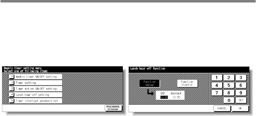
[9] Weekly Timer (continued)
[4] Lunch Hour Off Setting
Use this Lunch hour off function to shut down power for lunch break then turn on again
Only one off time interval can be programmed.
Weekly Timer Setting Menu Screen Lunch Hour Off Setting Screen
Procedure
1Touch [9] Weekly timer on the Key Operator Mode Screen.
Enter your 4-digit Weekly Timer master key code, then touch OK to display the Weekly
Timer Setting Menu Screen.
NOTE:
If an invalid Weekly Timer master key code is entered, continue by entering
the valid 4-digit code.
2Touch [4] Lunch hour off setting to display the Lunch Hour Off Setting Screen.
3Touch Function Valid to activate the Lunch hour off function.
Set OFF-time and Restart-time using the touch screen keypad, and then touch SET
after each entry.
4Touch Function Invalid to de-activate the Lunch hour off function. The time setting area
will appear grayed out and cannot be selected.
The Function Invalid setting is the factory default setting.
5Touch OK to complete the setting and return to the Weekly Timer Setting Menu Screen.
6Touch PREVIOUS SCREEN to restore the Key Operator Mode Screen.
7If no further changes are required, touch PREVIOUS SCREEN to restore the Basic
Screen to perform copying operations.
13-32
The Weekly Timer function turns the mfp ON and OFF once a day.
while the mfp is turned on due to the Weekly Timer function.
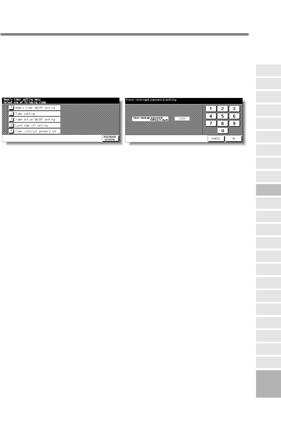
[9] Weekly Timer (continued)
[5] Timer Interrupt Password Setting
Use this password setting mode to establish a 4-digit password requirement for using
Timer Interrupt function.
The default password of 0000 allows the timer function to be interrupted without the
requirement for password entry.
Weekly Timer Setting Menu Screen Timer Interrupt Password Setting Screen
Procedure
1Touch [9] Weekly timer on the Key Operator Mode Screen.
Enter your 4-digit Weekly Timer master key code, then touch OK to display the Weekly
Timer Setting Menu Screen.
NOTE:
If an invalid Weekly Timer master key code is entered, continue by entering
the valid 4-digit code.
2Touch [5] Timer interrupt password set to display the Timer Interrupt Password
Setting Screen.
3Use the touch screen keypad to enter a 4-digit password, and then touch OK to
complete the setting and return to the Weekly Timer Setting Menu Screen.
NOTE:
When the password setting is 0000, timer interrupt can be used simply by
4Touch PREVIOUS SCREEN to restore the Key Operator Mode Screen.
5If no further changes are required, touch PREVIOUS SCREEN to restore the Basic
Screen to perform copying operations.
13
Key Operator
Mode
Non-Image
Area Erase
Scan
Transmission
Adjustment
Timing
Adjustment
HDD
Management
Finisher
Adjustment
Side 2 Lens
Adjustment
Call Remote
Centre
Machine
Management
List Print
Memory
Switch
Power Save
Setting
Tray Auto
Select Setting
Control Panel
Adjustment
Weekly
Timer
Key Operator
Data Setting
Panel Contrast/
Key Sound
Paper Type/
Special Size
Lock/Delete
Job Memory
E.C.M.
User Setting
Mode
Setting
System Initial
Setting
Key Operator
Mode
Centering
13-33
mfp Initial
turning the mfp OFF, then ON. In this case, you will be asked to enter the
duration of use (a period of time to turn the mfp power on).
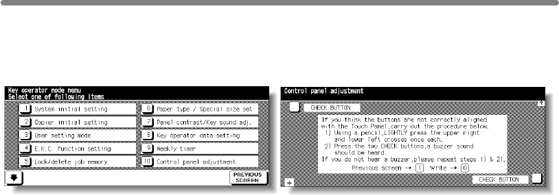
[10] Control Panel Adjustment
Use this feature to check the malfunction of the LCD touch screen due to the shift in
position of the touch sensor.
Key Operator Mode Screen Control Panel Adjustment Screen
Procedure
1Touch [10] Control panel adjustment on the Key Operator Mode Screen to display the
Control Panel Adjustment Screen.
2Touch the “+” indication at the upper right corner, then lower left corner on the screen.
The present coordinates will be displayed in the message area of the screen.
NOTE:
When touching the “+” indications, it is recommended that you use a sharp
point such as a pencil to be much more accurate.
3Check that the X coordinate and Y coordinate displayed in the first line of the message
area fall within the standard value displayed in the second line.
4Touch the CHECK BUTTONs at the upper left and lower right corners on the screen to
check if the buzzer tone functions normally.
5If the coordinates fall out of the range of the standard value in step 3, or the buzzer tone
does not sound in step 4, repeat the adjustment procedure from 2 to 4.
6Press [0] to write the new data, or press [1] to restore the Key Operator Mode Screen.
7If no further changes are required, touch PREVIOUS SCREEN to restore the Basic
Screen to perform copying operations.
13-34
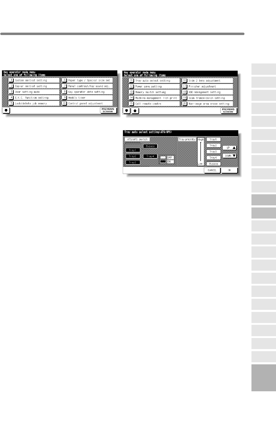
[11] Tray Auto Select Setting
Select to be detected or not to be detected, and priority of detection for each tray when
ATS/APS functions.
Key Operator Mode Screen 1 Key Operator Mode Screen 2
Tray Auto Select Setting Screen
Procedure
1Touch [11] Tray auto select setting on the Key Operator Mode Screen to display the
Tray Auto Select Setting Screen.
2On the left half of the screen, touch to highlight each tray key, then select OFF or ON to
specify whether the selected tray is to be automatically detected or not when ATS/APS
functions.
3Tray keys specified as ATS/APS ON will appear on the right half of the screen.
4Touch OK to complete the setting and restore the Key Operator Mode Screen.
5If no further changes are required, touch PREVIOUS SCREEN to restore the Basic
Screen to perform copying operations.
13
Key Operator
Mode
Non-Image
Area Erase
Scan
Transmission
Adjustment
Timing
Adjustment
HDD
Management
Finisher
Adjustment
Side 2 Lens
Adjustment
Call Remote
Centre
Machine
Management
List Print
Memory
Switch
Power Save
Setting
Tray Auto
Select Setting
Control Panel
Adjustment
Weekly
Timer
Key Operator
Data Setting
Panel Contrast/
Key Sound
Paper Type/
Special Size
Lock/Delete
Job Memory
E.C.M.
User Setting
Mode
Setting
System Initial
Setting
Key Operator
Mode
Touch to highlight the desired tray key, then change its priority by using Up (p) and
Down (q) arrow keys.
Centering
13-35
mfp Initial
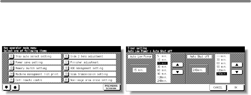
[12] Power Save Setting
Select the interval of time that must elapse before Auto Low Power and Auto Shut Off
become activated. Auto Shut Off conserves more energy than Auto Low Power. The
period of time selected for Auto Low Power cannot exceed the Auto Shut Off setting.
Key Operator Mode Screen Power Save Setting Screen
Procedure
1Touch [12] Power save setting on the Key Operator Mode Screen to display the Power
Save Setting Screen.
2The periods of time currently selected for each power save function are located on the
Timer Setting Screen below the Auto Low Power and Auto Shut Off indicators.
activating the Auto Low Power or Auto Shut Off.
NOTES:
1 The period of time selected for Auto Low Power cannot exceed the Auto
Shut Off setting.
2 If the same period of time as Auto Shut Off is selected for Auto Low
Power, the Auto Shut Off will function instead of Auto Low Power.
3Touch OK to complete the setting and restore the Key Operator Mode screen.
4If no further changes are required, touch PREVIOUS SCREEN to restore the Basic
Screen to perform copying operations.
Touch the arrow keys (p) and (q) in each area to select a specific waiting period before
13-36

[13] Memory Switch Setting
This function allows you to change the Memory Settings listed below.
See pp. 13-40~13-44 for details on Memory Settings.
SW No. Item Setting (default is underlined)
No. 01: Auto reset timer OFF / 30 sec. / 60 sec. / 90 sec. / 120 sec./
150 sec. / 180 sec. / 210 sec. / 240 sec. / 270
sec. / 300 sec.
No. 02: Full-Auto / Initial Setting
No. 03:
No. 04: Job memory auto recall (30) OFF / ON
No. 05: Finisher mode by Full-auto Face down (Sub tray) / Non-Sort / Sort /
Staple sort / Stitch&Fold / Fold / Face up (Sub
tray)
No. 06: Initial by Key counter insert OFF / ON
No. 07: Erasure outside area of orig.
Erased for except Platen (1:1) / Area outside of
orig. erased / Erased for APS/AMS only
No. 08: None / 1mm frame / 2mm frame / 3mm frame
/ 4mm frame / 5mm frame
No. 09: Automatic tray switching OFF / ON
No. 10: Platen APS OFF / ON
No. 11: OFF / ON
No. 12: Platen AMS OFF / ON
No. 13: OFF / ON
No. 14: Select tray when APS cancel APS preferential tray / Tray 1 / Tray 2 / Tray 3 /
Bypass tray
No. 15: Platen original size detect Only A series / Full size / AB series / Inch
series
No. 16: Only A series / Full size / AB series / Inch
series
No. 17:
Platen orig. size detect (SMALL)
A5R / B6R / 5.5"x8.5"R / B5 / A4 / 8.5"x11"
No. 18: Rotation ON-APS/AMS only
/ ON-APS/AMS/Reduce only
/ ON-Always
No. 19: Staple mode reset-function OFF / ON
No. 20: JOB offset operating OFF / ON
No. 21: Continuation print OFF / ON
No. 22: SDF Auto start OFF / ON-Memory mode only
No. 23: Key click sound OFF / ON
No. 24: 1 SHOT indication time 3 seconds / 5 seconds
No. 25: Power save screen Shut off mode / Low power mode
No. 26: START key latch function OFF / ON
No. 27: STOP key function JOB momentary stop / JOB cancel
No. 28: Auto select of Booklet copy Automatic selection / Non Automatic selection
No. 29: E.C.M. password under 8 digits / 8 digits
No. 30:
Arrow key change <Image Shift>
Decimal point off (1 STEP 1mm) / Decimal
point on (1 STEP 0.1mm)
No. 31: Exit direction (1 sheet, platen) Face up / Face down
No. 32:
An interruption suspended way
Division of a number of copies / During of a
number of copies
No. 33: E.C.M. password input timing Auto reset timer
/ complete job
13
Key Operator
Mode
Non-Image
Area Erase
Scan
Transmission
Adjustment
Timing
Adjustment
HDD
Management
Finisher
Adjustment
Side 2 Lens
Adjustment
Call Remote
Centre
Machine
Management
List Print
Memory
Switch
Power Save
Setting
Tray Auto
Select Setting
Control Panel
Adjustment
Weekly
Timer
Key Operator
Data Setting
Panel Contrast/
Key Sound
Paper Type/
Special Size
Lock/Delete
Job Memory
E.C.M.
User Setting
Mode
Setting
System Initial
Setting
Key Operator
Mode
AUTO RESET key function
selected
RADF-Original effect RADF+AUTO RESET key selected / RADF
RADF frame erasure selection
RADF APS
RADF AMS
RADF original size detect
Centering
13-37
mfp Initial
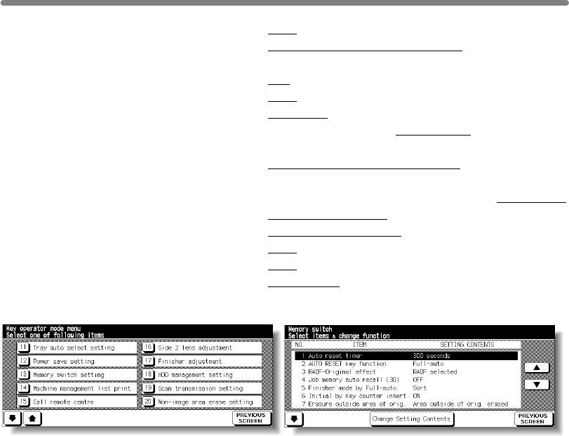
[13] Memory Switch Setting (continued)
No. 34:
Sound (No paper, toner/ JAM)
OFF / 3 seconds / 5 seconds / 10 seconds
No. 35: Reserve copy function Reserve copy by folder select / Reserve copy
by original set
No. 36: Scan stop by a pull out tray ON / OFF
No. 37:
Change page no. pos. (booklet)
OFF / ON (Outside page numbering)
No. 38:
Trimmer (STD/ Non STD size)
STD size / Non STD size
No. 39: Timer which prohibits Print OFF / 15 seconds / 30 seconds / 60 seconds /
90 seconds
No. 40: Bookmark function ON (It is cancel every JOB) / ON (It is not
cancel every JOB) / OFF
No. 41: Delete of overlay image Permission (Delete/Overwrite) / Prohibition
(Delete/Overwrite)
No. 42: Orig. direction/binding mode It is cancel every job / It is not cancel
No. 43: Image stored cont. (SRV) OFF / ON
No. 44: Image recalled cont. (SRV) OFF / ON
No. 45: Exit direction Face down / Face up
Key Operator Mode Screen Memory Switch Setting Screen
Procedure
1Touch [13] Memory switch setting on the Key Operator Mode Screen to display the
Memory Switch Setting Screen.
2Use the procedure below to select the desired item and change the setting.
select the desired item.
(3) Touch Change Setting Contents to change the setting of the highlighted item.
(4) Repeat above steps (1) to (3) to make several changes in succession.
3Touch PREVIOUS SCREEN to restore the Key Operator Mode Screen.
4If no further changes are required, touch PREVIOUS SCREEN to restore the Basic
Screen to perform copying operations.
The following functions can be provided by the Memory switch settings.
[1] Auto reset timer
Set the reset interval starting from the completion of a copying job until the machine
returns to the initial condition.
[2] AUTO RESET key function
Set the condition of the following modes when [AUTO RESET] is pressed: Copy mode,
Copy density, Magnification, Tray selection.
(1) Touch the arrow keys p and q at the right on the Memory Switch Setting Screen to
(2) Touch the arrow keys Çand È at the lower left to scroll the screen.
13-38

[4] Job memory auto recall (30)
Job memory No. 30 is automatically recalled when power is turned on or when Auto
Reset is restored.
This job recall function works only when Job No. 30 is registered.
[5] Finisher mode by AUTO RESET
Set the Finisher mode to be recalled when [AUTO RESET] is pressed.
[6] Initial by Key counter insert
Set the machine to return to the initial state when Key counter is inserted.
[7] Erasure outside area of original
Set the machine to delete the outside area of original.
[9] Automatic tray switching
to another tray that contains the same size paper.
[10] Platen APS
platen glass. (In reduction or enlargement mode, an appropriate paper size is selected
according to the ratio selected.)
[12] Platen AMS
magnification ratio to correspond to the selected paper size.
[14] Select tray when APS cancel
Select the tray to be automatically selected when APS is released.
[15] Platen original size detect
Select the series of the original paper size detected from the platen glass.
13
Key Operator
Mode
Non-Image
Area Erase
Scan
Transmission
Adjustment
Timing
Adjustment
HDD
Management
Finisher
Adjustment
Side 2 Lens
Adjustment
Call Remote
Centre
Machine
Management
List Print
Memory
Switch
Power Save
Setting
Tray Auto
Select Setting
Control Panel
Adjustment
Weekly
Timer
Key Operator
Data Setting
Panel Contrast/
Key Sound
Paper Type/
Special Size
Lock/Delete
Job Memory
E.C.M.
User Setting
Mode
Setting
System Initial
Setting
Key Operator
Mode
[13] Memory Switch Setting (continued)
according to the ratio.)
appropriate ratio for the copy when paper size is selected manually.
[3] RADF-Original effect
Set the machine condition when original is set on RADF in non-RADF mode with RADF
unit closed.
[8] RADF frame erasure selection
Set Frame erasure to function anytime in RADF mode.
[11] RADF APS
RADF. (In reduction/enlargement mode, an appropriate paper size is selected
[13] RADF AMS
Centering
13-39
mfp Initial
When paper is depleted during a copying job, the mfp continues copying by switching
The mfp automatically selects the same size copy paper as the original placed on the
After detecting the original size placed on the RADF the mfp automatically selects an
The mfp automatically selects the same size copy paper as the original placed on the
The mfp detects the size of the platen original and selects the appropriate

[13] Memory Switch Setting (continued)
[17] Platen orig. size detect (SMALL)
Select the minimum original paper size detected from the platen glass.
[18] Rotation
Select to activate, activate the Rotation only when the APS/AMS functions, or activate
the Rotation only when the APS/AMS/reduce functions.
[19] Staple mode reset-function
Staple mode is automatically canceled after a job is completed with Staple sort mode
ON. (Sort mode is selected.)
[20] JOB offset operating
[21] Continuation print
[22] SDF Auto start
[23] Key click sound
Activate or deactivate the sound each time a key is pressed on the touch panel.
[24] 1 SHOT indication time
Select the SHOT indication time function.
[25] Power save screen
[26] START key latch function
Activate or deactivate the latch function.
[27] STOP key function
Select to display or not to display the confirmation message when [STOP] key is
pressed.
[28] Auto select of Booklet copy
[29] E.C.M. password
[30] Arrow key change (Image Shift)
Select the 1 step unit of the touch key to specify the shift amount in Image shift.
to feed the SDF original.
when Stitch&Fold or Fold output mode is selected.
[16] RADF original size detect
Select the series of the original paper size detected from the RADF.
Select to feed the SDF original automatically when placed on the RADF, press [START]
Select the acceptable number of digits for the ECM master key code.
Select the screen to display when pressing the [SLEEP ON/OFF] key.
13-40
Set the mfp to offset the copies of different jobs.
Set the mfp to output multiple reserve jobs in succession.
Set the mfp with Q3220A mounted to automatically select the Booklet mode

[13] Memory Switch Setting (continued)
[31] Exit direction of 1 sheet
Select to exit face up or face down when making only 1 sheet of copy.
[32] An interruption suspended way
Select the timing to stop the job in progress when [INTERRUPT] is pressed.
[33] E.C.M. password input timing
[34] Sound (No paper/JAM)
Select the duration of the buzzer for alerting that the machine has stopped being out of
paper or due to paper misfeed.
[35] Reserve copy function
Set the selection for the reserve job setting.
[36] Scan stop by a pull out tray
Select to stop or continue the scanning job when a tray is pulled out.
[37] Change page no. pos. (booklet)
Set the machine to position the page numbers automatically on the outside edges of
the copy when using Booklet with Page Numbering in Stamp.
[38] Trimmer (STD/ Non STD size) (Function invalid)
Set the machine to allow trimming the folded or stapled & folded sheets in non-standard
size (or wide size).
[39] Timer which prohibits Print
Set the timer to allow the printing job after operating the copying job.
[40] Bookmark function
Select to set the Bookmark function only for the current job, set for all the following jobs,
or deactivate the function.
[41] Delete of overlay image
In Overlay Memory setting, select to permit or prohibit deleting the selected image data
previously stored in HDD, and also overwriting the data of the same name when storing
new data in HDD.
[42] Orig. direction/binding mode
Select to reset or save the original direction and bind position settings made on the
Special Original popup menu and Output Mode popup menu after completion of each
copying job.
[43] Image stored cont. (SRV)
When storing the image data in HDD/PC in scan/server mode, select to release or
continue the scan/server mode after completion of each image data storing job.
13
Key Operator
Mode
Non-Image
Area Erase
Scan
Transmission
Adjustment
Timing
Adjustment
HDD
Management
Finisher
Adjustment
Side 2 Lens
Adjustment
Call Remote
Centre
Machine
Management
List Print
Memory
Switch
Power Save
Setting
Tray Auto
Select Setting
Control Panel
Adjustment
Weekly
Timer
Key Operator
Data Setting
Panel Contrast/
Key Sound
Paper Type/
Special Size
Lock/Delete
Job Memory
E.C.M.
User Setting
Mode
Setting
System Initial
Setting
Key Operator
Mode
Centering
Set the input timing for the ECM password.
13-41
mfp Initial

[13] Memory Switch Setting (continued)
[44] Image recalled cont. (SRV)
When recalling the image data stored in HDD/PC in scan/server mode, select to recall
only one job or to continue recalling jobs.
[45] Exit direction
Select to exit face up or face down when making single-sided copies in non-sort or sort
mode using finisher primary (main) tray.
13-42
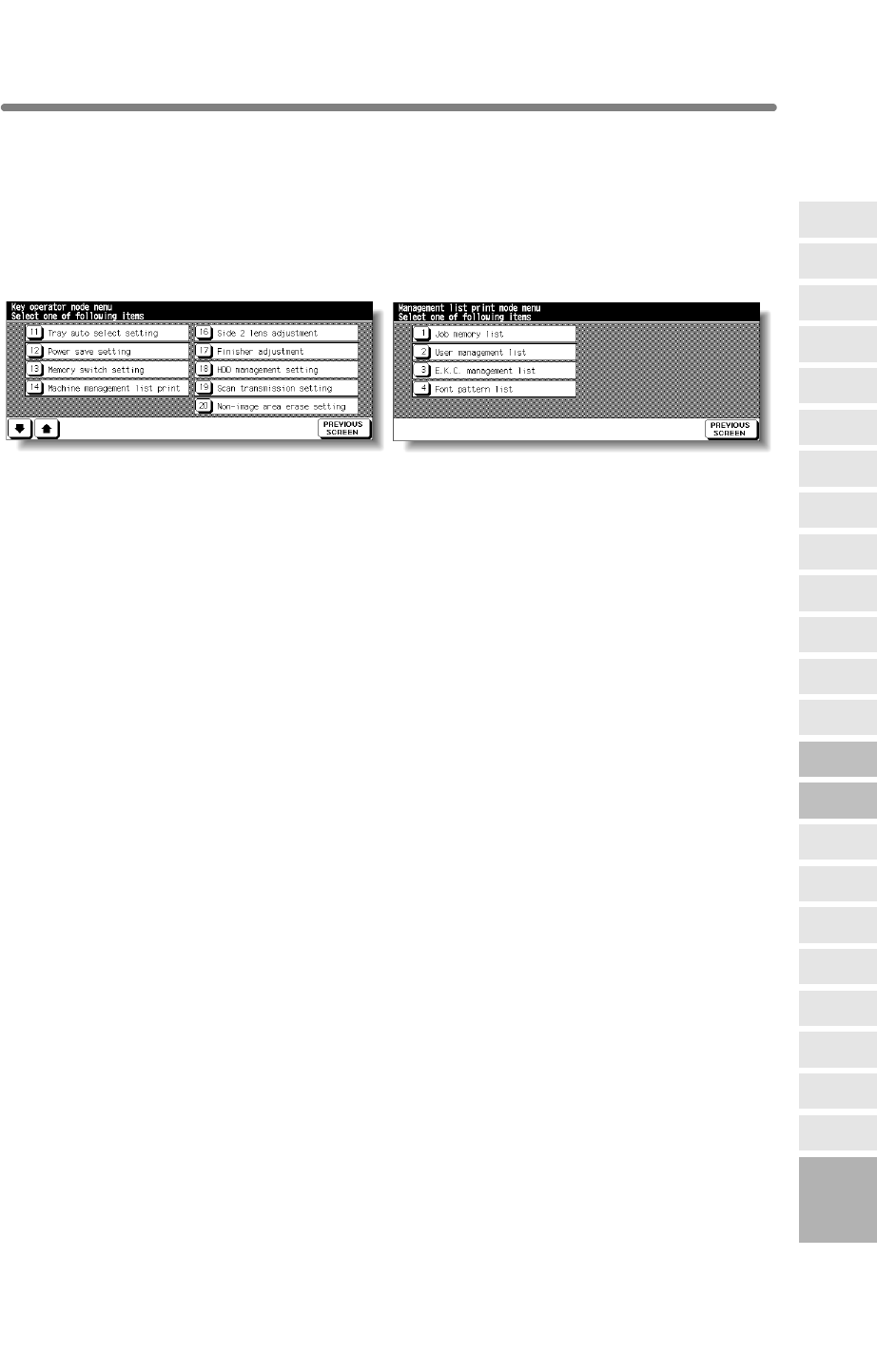
[14] Machine Management List Print
Use this function to print out the list selected from the following items.
• Job memory list: Programmed contents of Job memory
• User management list: Home position settings selected by user
• Font pattern list: Font patterns used in the machine
Key Operator Mode Screen Management List Print Menu Screen
Procedure
1Touch [14] Machine management list print on the Key Operator Mode Screen to
display the Management List Print Menu Screen.
2Touch the desired item on the screen. The Basic Screen will resume automatically.
3Press [START] to start printing the selected list.
To suspend printing, press [STOP]. Press [P] and [C] in order to return to the
Management List Print Menu Screen.
4Touch PREVIOUS SCREEN to restore the Key Operator Mode Screen.
5If no further changes are required, touch PREVIOUS SCREEN to restore the Basic
Screen to perform copying operations.
13
Key Operator
Mode
Non-Image
Area Erase
Scan
Transmission
Adjustment
Timing
Adjustment
HDD
Management
Finisher
Adjustment
Side 2 Lens
Adjustment
Call Remote
Centre
Machine
Management
List Print
Memory
Switch
Power Save
Setting
Tray Auto
Select Setting
Control Panel
Adjustment
Weekly
Timer
Key Operator
Data Setting
Panel Contrast/
Key Sound
Paper Type/
Special Size
Lock/Delete
Job Memory
E.C.M.
User Setting
Mode
Setting
System Initial
Setting
Key Operator
Mode
Centering
• E.C.M. management list:Machine informations managed by ECM
13-43
mfp Initial
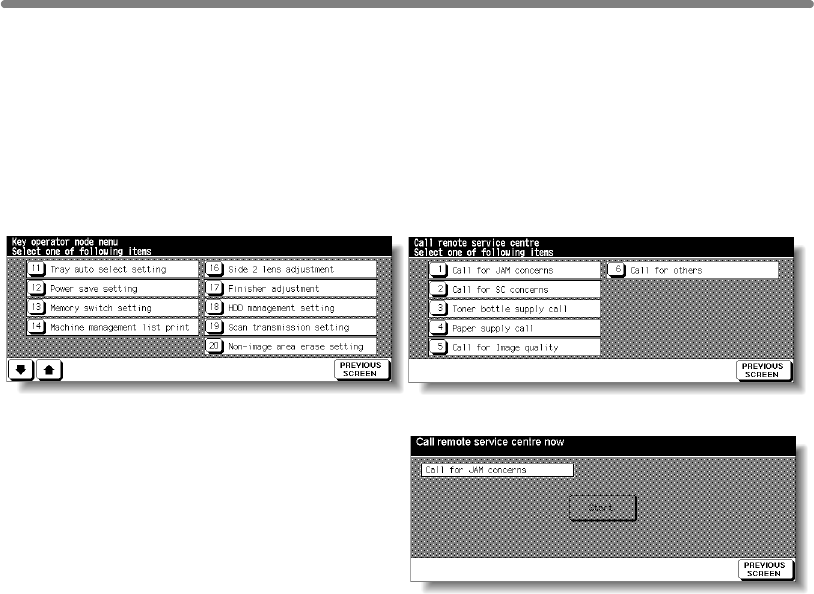
[15] Call Remote Centre
❒Setting options: Call for JAM concerns, Call for SC concerns, Toner bottle supply call, Paper
supply call, Call for image quality, Call for others
Key Operator Mode Screen Call Remote Service Centre Screen
Start Call Screen
Procedure
1Touch [15] Call remote centre on the Key Operator Mode Screen to display the Call
Remote Service Centre Screen.
2Touch [1] Call for JAM concerns; [2] Call for SC concerns; [3] Toner bottle supply
call; [4] Paper supply call; [5] Call for Image quality; or [6] Call for others.
The Start Call Screen will be displayed.
3Touch Start to call.
4Touch PREVIOUS SCREEN to restore the Key Operator Mode Screen.
5If no further changes are required, touch PREVIOUS SCREEN to restore the Basic
Screen to perform copying operations.
When activated, the Remote Diagnostics option is automatically monitored by a hp
service representative. In case of machine trouble, select the Call Remote Centre
option. Your service representative will contact you to determine the appropriate means
for resolving the problem.
13-44
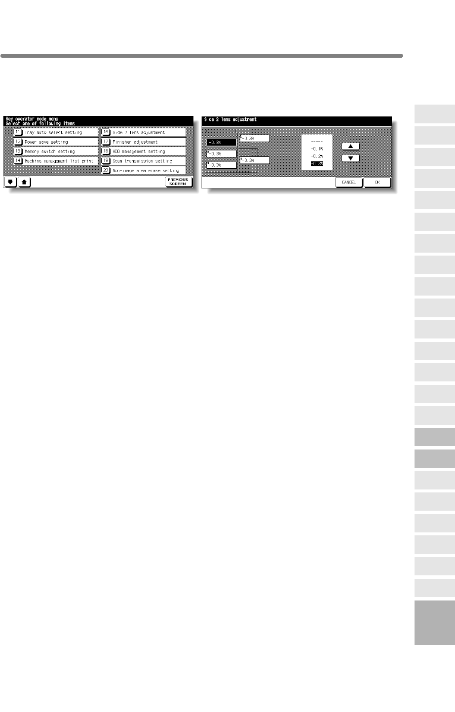
[16] Side 2 Lens Adjustment
Use this function to set the adjustment data of the magnification ratio for each tray as
Side 2.
Key Operator Mode Screen Side 2 Lens Adjustment Screen
Procedure
1Touch [16] Side 2 lens adjustment on the Key Operator Mode Screen to display the
Side 2 Lens Adjustment Screen.
2Touch to highlight the desired tray key, then touch arrow keys to select an adjustment
data.
The selected data will be displayed on the highlighted tray key.
3Touch OK to complete the setting and return to the Key Operator Mode Screen.
4If no further changes are required, touch PREVIOUS SCREEN to restore the Basic
Screen to perform copying operations.
13
Key Operator
Mode
Non-Image
Area Erase
Scan
Transmission
Adjustment
Timing
Adjustment
HDD
Management
Finisher
Adjustment
Side 2 Lens
Adjustment
Call Remote
Centre
Machine
Management
List Print
Memory
Switch
Power Save
Setting
Tray Auto
Select Setting
Control Panel
Adjustment
Weekly
Timer
Key Operator
Data Setting
Panel Contrast/
Key Sound
Paper Type/
Special Size
Lock/Delete
Job Memory
E.C.M.
User Setting
Mode
Setting
System Initial
Setting
Key Operator
Mode
Centering
13-45
mfp Initial
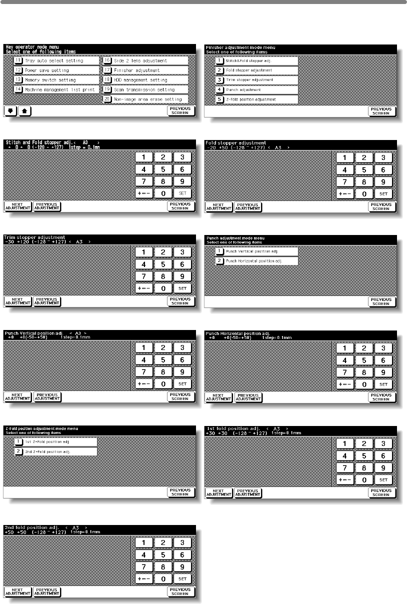
[17] Finisher Adjustment
Use this mode to make fine adjustments to each function of the finisher.
Key Operator Mode Screen Finisher Adjustment Menu Screen
Stitch&Fold Stopper Position Adjustment Screen
Fold Stopper Position Adjustment Screen
Trim Stopper Adjustment Screen Punch Adjustment Menu Screen
Punch Vertical Position Adjustment Screen Punch Horizontal Position Adjustment Screen
Z-Fold Position Adjustment Menu Screen 1st Fold Position Adjustment Screen
2nd Fold Position Adjustment Screen
13-46

[17] Finisher Adjustment (continued)
Procedure
1Touch [17] Finisher adjustment on the Key Operator Mode Screen to display the
Finisher Adjustment Menu Screen.
2Touch the desired menu key to display the adjustment screen for each function.
3Make fine adjustment on the screen. To go on or back to another adjustment screen,
touch NEXT ADJUSTMENT or PREVIOUS ADJUSTMENT. Touching PREVIOUS
SCREEN restores the Finisher Adjustment Menu Screen.
4Touch PREVIOUS SCREEN to restore the Key Operator Mode Screen.
5If no further changes are required, touch PREVIOUS SCREEN to restore the Basic
Screen to perform copying operations.
13
Key Operator
Mode
Non-Image
Area Erase
Scan
Transmission
Adjustment
Timing
Adjustment
HDD
Management
Finisher
Adjustment
Side 2 Lens
Adjustment
Call Remote
Centre
Machine
Management
List Print
Memory
Switch
Power Save
Setting
Tray Auto
Select Setting
Control Panel
Adjustment
Weekly
Timer
Key Operator
Data Setting
Panel Contrast/
Key Sound
Paper Type/
Special Size
Lock/Delete
Job Memory
E.C.M.
User Setting
Mode
Setting
System Initial
Setting
Key Operator
Mode
Centering
13-47
mfp Initial
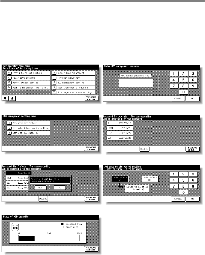
[18] HDD Management Setting
Use this function to manage the image data stored in the HDD and to check the space
available for new data.
• Password list/delete: Display the password list on the screen, or delete the image
data (JOB) by deleting the corresponding password from the list.
• JOB auto delete period setting: Specify the period of time (1 to 52 weeks) to keep
data so that it will be deleted automatically when specified period has passed.
• State of HDD capacity: Check the space in percentage.
Key Operator Mode Screen HDD Management Password Entry Screen
HDD Management Setting Menu Screen Password List/Delete Screen
Password List/Delete Screen JOB Auto Delete Period Setting Screen
State of HDD Capacity Screen
13-48

[18] HDD Management Setting (continued)
Procedure
1Touch [18] HDD management setting on the Key Operator Mode Screen.
The HDD Management Password Entry Screen will be displayed when the 4-digit HDD
management password is set by service representative.
Otherwise, the HDD Management Setting Menu Screen displays without the password
requirement.
If the HDD Management Password Entry Screen is displayed, use the keypad on the
touch screen to enter your 4-digit HDD management password; then touch OK to
display the HDD Management Setting Menu Screen.
NOTE:
The HDD management password is not initially set. Contact your service
representative, if desired.
2Touch the desired menu key to display the subsequent screen for each function.
To view the password list or delete the password and the corresponding image data:
(1) Touch [1] Password list/delete to display the Password List/Delete Screen.
(2) Touch to highlight the password key to be deleted, then touch DELETE. The popup
menu will appear for confirmation.
(3) Touch YES to delete the selected password and all the data corresponding to it or
touch NO to cancel.
(4) Touch PREVIOUS SCREEN to return to the HDD Management Setting Menu
Screen.
To delete the password and data automatically:
(1) Touch [2] JOB auto delete period setting to display the Job Auto Delete Period
Setting Screen.
(2) Touch Auto delete ON to highlight it, then enter the number of weeks to keep each
data, using the touch screen keypad. The maximum period of time is 52 weeks.
(3) Touch OK to complete the setting.
To check the current state of HDD capacity:
(1) Touch [3] State of HDD capacity to display the State of HDD Capacity Screen. The
bar chart on the screen shows the current state of HDD capacity.
(2) Touch PREVIOUS SCREEN to return to the HDD Management Setting Menu
Screen.
3Touch PREVIOUS SCREEN to restore the Key Operator Mode Screen.
4If no further changes are required, touch PREVIOUS SCREEN to restore the Basic
Screen to perform copying operations.
13
Key Operator
Mode
Non-Image
Area Erase
Scan
Transmission
Adjustment
Timing
Adjustment
HDD
Management
Finisher
Adjustment
Side 2 Lens
Adjustment
Call Remote
Centre
Machine
Management
List Print
Memory
Switch
Power Save
Setting
Tray Auto
Select Setting
Control Panel
Adjustment
Weekly
Timer
Key Operator
Data Setting
Panel Contrast/
Key Sound
Paper Type/
Special Size
Lock/Delete
Job Memory
E.C.M.
User Setting
Mode
Setting
System Initial
Setting
Key Operator
Mode
Centering
13-49
mfp Initial
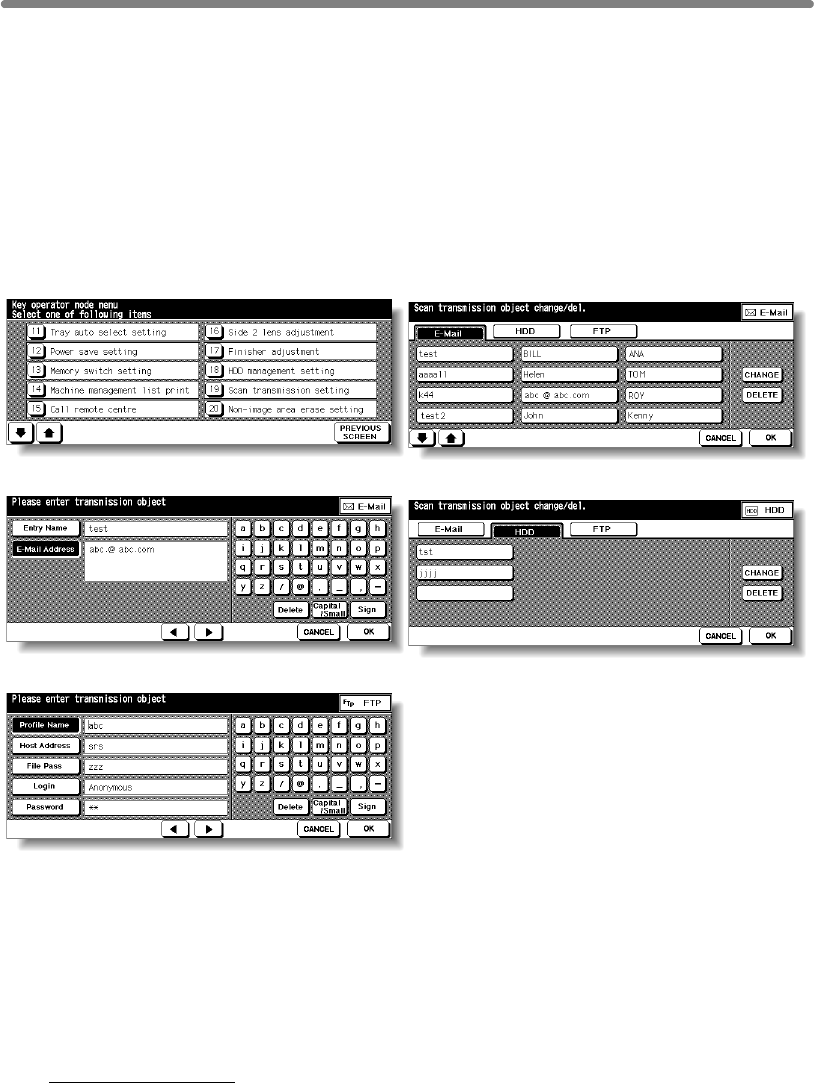
[19] Scan Transmission Setting
Use this function to change or delete the address registered for transmitting the image
data scanned on the machine.
The following three address types can be registered.
•E-mail
• HDD (box No.)
• FTP (FTP server address)
NOTE:
The [19] Scan Transmission Setting key will function only when IP-602
Printer Controller is installed in the machine.
Key Operator Mode Screen Scan Transmission Setting Screen
Change E-Mail Address Screen Change Box No. Screen
Change FTP Address Screen
Procedure
1Touch [19] Scan transmission setting on the Key Operator Mode Screen to display
the Scan Transmission Setting Screen.
2Select the desired address type.
Touch E-Mail, HDD, or FTP to display the registered name keys on each page.
3Select the name key to be changed or deleted.
To delete the address:
Touch to highlight the desired name key, then touch DELETE.
The selected key will be deleted from the screen.
Touch the È Lower arrow key to scroll, or ÇUpper arrow key to return.
13-50

[19] Scan Transmission Setting (continued)
To change the address:
(1) Touch to highlight the desired name key, then touch CHANGE.
The subsequent screen according to the address type will be displayed. (See
previous page.)
(2) Touch to highlight the registered item key on the left, then change the information
under that key using the alphabet keys on the screen.
(3) Touch OK on each screen to complete the setting and restore the Scan
Transmission Setting Screen.
4Touch OK to restore the Key Operator Mode Screen.
5If no further changes are required, touch PREVIOUS SCREEN to restore the Basic
Screen to perform copying operations.
13
Key Operator
Mode
Non-Image
Area Erase
Scan
Transmission
Adjustment
Timing
Adjustment
HDD
Management
Finisher
Adjustment
Side 2 Lens
Adjustment
Call Remote
Centre
Machine
Management
List Print
Memory
Switch
Power Save
Setting
Tray Auto
Select Setting
Control Panel
Adjustment
Weekly
Timer
Key Operator
Data Setting
Panel Contrast/
Key Sound
Paper Type/
Special Size
Lock/Delete
Job Memory
E.C.M.
User Setting
Mode
Setting
System Initial
Setting
Key Operator
Mode
Centering
13-51
mfp Initial
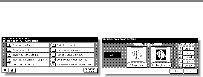
[20] Non-Image Area Erase Setting
Select the mode of Non-Image Area Erase function to be in effect when this feature is
selected on the Application Selection Screen after power is turned on or after Auto
Reset occurs.
Key Operator Mode Screen Non-Image Area Erase Setting Screen
Procedure
1Touch [20] Non-image area erase setting on the Key Operator Mode Screen to display
the Non-Image Area Erase Setting Screen.
2Select the desired erase mode and original density level.
Touch AUTO to let the machine select the erase mode and density level automatically.
To specify the erase mode manually, touch Oblique erase or Rectangle erase, as
desired, then select the density level required. Five exposure levels are provided.
NOTE:
Select AUTO mode if the specified Oblique or Rectangle Erase mode does
not function properly due to the type of set original.
3Touch OK to complete the setting and restore the Key Operator Mode Screen.
4If no further changes are required, touch PREVIOUS SCREEN to restore the Basic
Screen to perform copying operations.
13-52
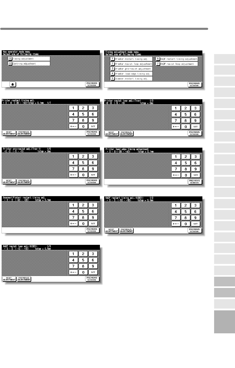
[21] Timing Adjustment
Use this mode to make fine adjustments of the timing for printing or scanning function.
Key Operator Mode Screen Timing Adjustment Menu Screen
Printer Restart Timing Adjustment Screen Printer Resist Loop Adjustment Screen
Printer Pre-resist Adjustment Screen Printer Lead Edge Timing Adjustment Screen
13
Key Operator
Mode
Non-Image
Area Erase
Scan
Transmission
Adjustment
Timing
Adjustment
HDD
Management
Finisher
Adjustment
Side 2 Lens
Adjustment
Call Remote
Centre
Machine
Management
List Print
Memory
Switch
Power Save
Setting
Tray Auto
Select Setting
Control Panel
Adjustment
Weekly
Timer
Key Operator
Data Setting
Panel Contrast/
Key Sound
Paper Type/
Special Size
Lock/Delete
Job Memory
E.C.M.
User Setting
Mode
Setting
System Initial
Setting
Key Operator
Mode
Scanner (Platen) Restart Timing Adjustment Screen
RADF Restart Timing Adjustment Screen
RADF Resist Loop Adjustment Screen
Centering
13-53
mfp Initial

[21] Timing Adjustment (continued)
Procedure
1Touch [21] Timing adjustment on the Key Operator Mode Screen to display the Timing
Adjustment Menu Screen.
2Touch the desired menu key to display the adjustment screen for each function.
3Make fine adjustment on the screen. To go on or back to another adjustment screen,
touch NEXT ADJUSTMENT or PREVIOUS ADJUSTMENT. Touching PREVIOUS
SCREEN restores the Timing Adjustment Menu Screen.
4Touch PREVIOUS SCREEN to restore the Key Operator Mode Screen.
5If no further changes are required, touch PREVIOUS SCREEN to restore the Basic
Screen to perform copying operations.
13-54
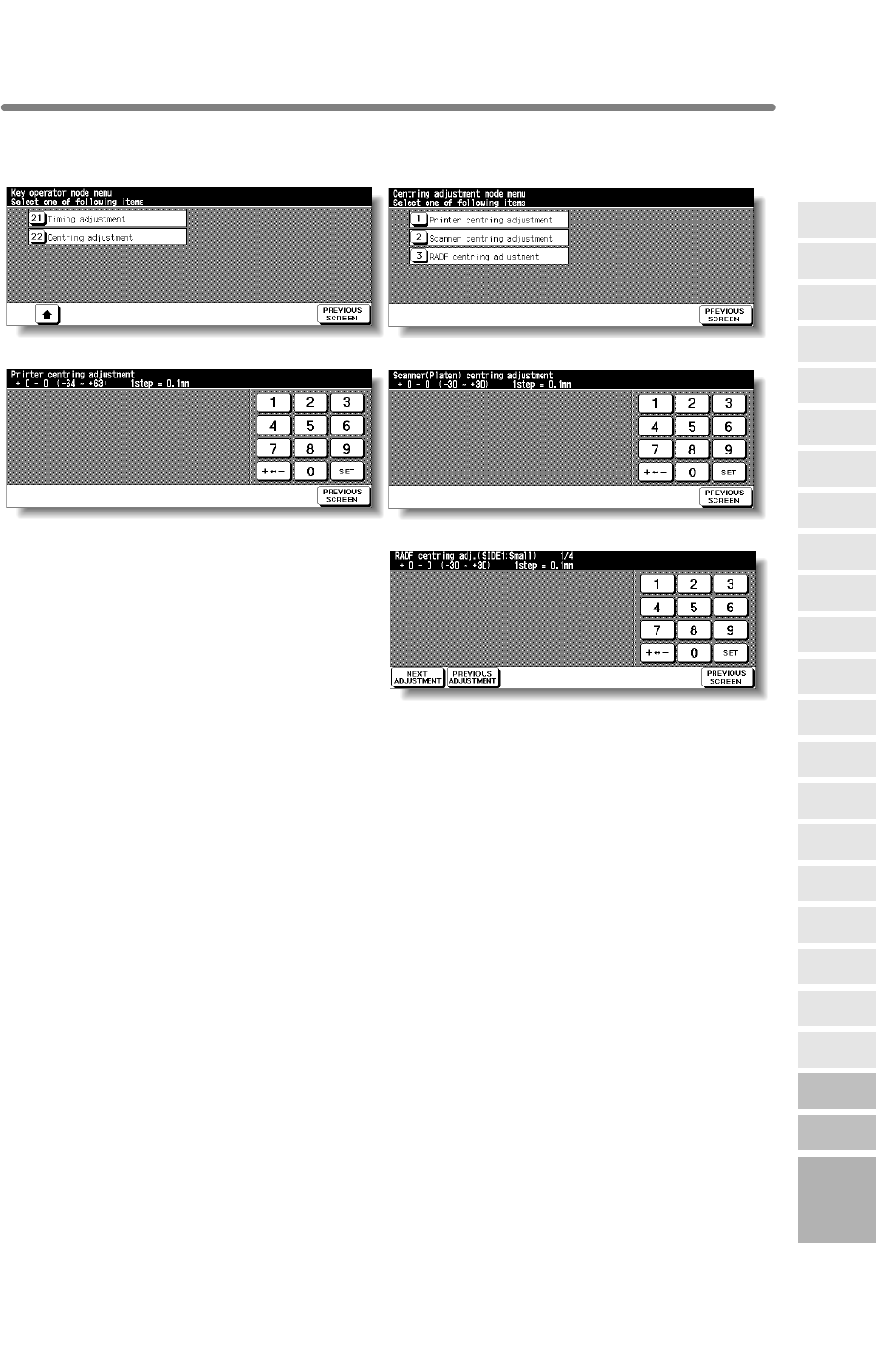
Key Operator Mode Screen
Procedure
1
2
3Make fine adjustment on the screen. To go on or back to another adjustment screen,
4Touch PREVIOUS SCREEN to restore the Key Operator Mode Screen.
5If no further changes are required, touch PREVIOUS SCREEN to restore the Basic
Screen to perform copying operations.
13
Key Operator
Mode
Non-Image
Area Erase
Scan
Transmission
Adjustment
Timing
Adjustment
HDD
Management
Finisher
Adjustment
Side 2 Lens
Adjustment
Call Remote
Centre
Machine
Management
List Print
Memory
Switch
Power Save
Setting
Tray Auto
Select Setting
Control Panel
Adjustment
Weekly
Timer
Key Operator
Data Setting
Panel Contrast/
Key Sound
Paper Type/
Special Size
Lock/Delete
Job Memory
E.C.M.
User Setting
Mode
Setting
System Initial
Setting
Key Operator
Mode
[22] Centering Adjustment
Use this mode to make fine adjustments of the image centering function.
Centering Adjustment Menu Screen
Printer Centering Adjustment Screen Scanner (Platen) Centering Adjustment Screen
RADF Centering Adjustment Screen
Touch [22] Centering adjustment on the Key Operator Mode Screen to display the
Touch the desired menu key to display the adjustment screen for each function.
touch NEXT ADJUSTMENT or PREVIOUS ADJUSTMENT. Touching PREVIOUS
Centering Adjustment Menu Screen.
SCREEN restores the Centering Adjustment Menu Screen.
Centering
13-55
mfp Initial
blank page
13-56

i
Index
Number
1.00 Magnification mode 3-15
1-2 Copying 3-21
2 in 1, 4 in 1, 8 in 1 copying 9-10
2 Repeat, 4 Repeat, 8 Repeat 9-34
2-1 Copying 3-27
2-2 Copying 3-21
A
ADD PAPER key 5-10
ADD TONER icon 12-2
Adding Toner 12-2
AE key 3-18
AMS (Automatic Magnification Selection) 3-13
APPLICATION key 9-2
Application Selection Screen 9-2
APS (Automatic Paper Selection) 3-11
AUTO Layout 9-40
Auto Low Power 2-20
Auto Shut-Off 2-20
Automatic Exposure (AE) 3-18
B
Basic Screen 2-14
Binding Margin 9-47
Binding Mode 3-48
BOOK MARK key 9-2
Booklet 9-13
Booklet mode outlet 2-6
Booklet tray 2-6
C
C (CLEAR QTY.) key 3-7
“Call for Service” message 5-2
Call for Service Screen 5-2
Cartridge housing 2-7
CAUTION 1-4
Caution Indicator 1-2
Caution label 1-2
Chapter 9-7
CHECK key 3-50
Check Mode 3-50
Checking Copy Count 12-15
Cleaning image scanning section 12-13
Combination 9-10
Control Panel 2-16
Conveyance fixing unit 2-4
Counter List Screen 12-15
D
DANGER 1-4
Density Level 3-18
Density Shift 3-20
DIMM 10-2
Double-sided copy 3-21
Double-sided original 3-27
Drum unit 2-4
Dual Page 9-21
E
Empty waste basket 12-9, 12-11
Environment 1-6
Extension Cord 1-5
1u2, 2u2 3-21
2u1 3-27
Delete image data from HDD 10-8
1 SHOT indication time 13-40
An interruption suspended way 13-41
Arrow key change (Image Shift) 13-40
AUTO RESET key function 13-38
Centering Adjustment 13-55
Change page no. pos. (booklet) 13-41
Continuation print 13-40
Control Panel Adjustment 13-34
Cover Sheet Feeding 7-19
Copy Limit 13-15
Date & Time Setting 13-4
Delete of overlay image 13-41
Diff. time setting 13-4
Auto reset timer 13-38
Auto select of Booklet copy 13-40
Automatic tray switching 13-39
Bookmark function 13-41
Call Remote Centre 13-44
E.C.M. (Electronic Key Counter) 13-13
E.C.M. All Count Reset 13-18
E.C.M. Data Edit 13-15
E.C.M. Function Setting 13-19
E.C.M. management list 13-43
E.C.M. password (Memory Switch) 13-40
E.C.M. password input timing 13-41
ECM master key code 13-14
ECM password 2-22, 13-13, 13-15
E-Mail Transmission Setting 13-7
Erasure outside area of original 13-39
Exit direction 13-42
Exit direction of 1 sheet 13-41

ii
Index
F
Finisher door 2-6
Fixed magnification mode (RE) 3-16
Fixing unit 2-4
Fold mode 7-8
Frame/Fold Erasure 9-37
FREE JOB key 3-34
Front door 2-3
Full-Image Area 9-42
G
Gateway address 13-7
Guide width for mixed originals 11-9
H
HELP key 4-6
Help Menu Screen 4-7
Help Mode 4-6
I
Image data password 10-5
Image Insert 9-18
Image scanning section 12-13
Image Shift 9-44
Image Store/Delete mode 10-4
Increase Contrast mode (Enhance) 8-4
Inserting a new staple cartridge 12-5
Installation Space 1-7
Interleaf sheet 9-16
INTERRUPT key 3-53
Interrupt Mode 3-53
IP Address Setting 13-7
J
JAM JOB key 5-8
JOB MEMORY key 4-2
Job Recall 4-5
Job Status Screen 3-37
Job Store 4-2
K
Key Operator Mode 13-2
KEY OPERATOR MODE key 13-2
Key Operator Mode Screen 13-3
Key Operator password 13-2
L
Language Select Setting 13-6
LCD touch screen 2-3, 2-16
Left partition glass 12-13
Line speed setting 13-7
Loading Paper 2-23
Loading Tabbed Sheets 2-28
Low Power Mode 2-20
M
Manual finishing operation panel 2-8
Manual staple 7-22
Manual stitch & fold mode 7-22
“Memory Full” message 5-11
Memory Overflow 5-11
Mishandled paper 5-6
Mixed Original 8-6
MODE key 10-4
Multi-sheet bypass tray 3-29
Q3219A/Q3220A Finisher 2-6
Q3637A/Q3638A Tray 4 /HCI 2-9
HDD STORE key 10-11
Image Recall mode 10-14
Image Store&Output mode 10-11
Finisher Adjustment 13-46
Finisher mode by AUTO RESET 13-39
Font pattern list 13-43
FTP server address 13-50
HDD Management Setting 13-48
Image recalled cont. (SRV) 13-42
Image stored cont. (SRV) 13-41
Initial by Key counter insert 13-39
Initial Setting 13-8
Job memory auto recall (30) 13-39
Job memory list 13-43
Job offset operating 13-40
Key click sound 13-40
Key Operator Data Setting 13-24
Lens Mode 3-13
Lock icon 13-20
Lock/Delete Job Memory 13-20
Lunch Hour Off Setting 13-32
Machine Management List Print 13-43
Memory Switch Setting 13-37
Limited use of the mfp 5-3
mfp Initial Setting 13-8

iii
Index
N
Non-Image Area Erase 9-27
Non-standard size originals 8-12
NORMAL key 3-18
O
OHP Interleave 9-16
Original direction 8-2
Original Form 8-12
Original Information 11-8
Output Mode with Finisher 3-43
Output Mode without Finisher 3-40
Overlay 9-59
P
P (COUNTER) key 2-16, 5-4, 12-15
Page space function 9-46
Paper indicator 2-23
Paper Information 11-2
Paper jam position display 5-6
Paper Size 3-11
Paper size for trays and equipments 11-5
Paper Weight 11-2
Periodic Check 1-10
Photo mode (Enhance) 8-4
Platen glass originals 11-8
Platen store mode 3-32
Plug Socket 1-5
PM CALL icon 5-4
PM counter 5-4
Positioning Mixed Originals 3-3
Positioning Originals 3-2
Positioning Original on Platen Glass 3-6
Positioning SDF Original 3-5
Power cord 1-5
Power OFF/ON Screen 5-13
Power switch 2-3
Precautions 1-9
PRE-JOB RECALL key 3-49
Preventive Maintenance 5-4
Previous job setting 3-49
Primary (main) tray 2-6
Program Job 9-25
Proof Copy 3-50
R
RE key 3-16
Reduce & Shift 9-47
Remote Diagnostics option 5-2
Repeat 9-31, 9-34
Report code No. 5-2
Reserve 3-34
Reset switch 2-4
Reverse Image 9-29
Right&Left Bind 3-48
ROTATION OFF key 7-4
Routine Handling 1-9
S
AN/SERVER LED 10-4
DF 8-10
condary (sub) tray 2-6
rver functions 10-2
tting Print Quantity 3-7
eet/Cover Insertion 9-3
PROOF COPY key 3-52
Punch mode 7-11
Q3222A/Q5684A Punching Unit 2-12
Q3221A Cover Sheet Feeder 2-8
Overlay Memory 9-61
RADF 2-3
RADF store mode 3-32
RADF originals 11-9
RADF platen guide cover 12-14
Positioning Z-Folded Originals 3-4
SLEEP ON/OFF key 2-20, 7-2
Power source 1-5
Power Plug 1-5
PECIAL ORIGINAL key 8-2
ingle-sided copy 3-27
SC
S
Se
Se
Se
Sh
S
S
Special Original popup menu 8-2
Special paper in Multi-sheet bypass tray 11-7
Stacker unit 2-7
Non-Image Area Erase Setting 13-52
Orig. direction/binding mode 13-41
Panel Contrast / Key Sound Adjustment 13-23
Paper Type / Special Size Set 13-21
Platen AMS 13-39
Platen APS 13-39
Platen orig. size detect (SMALL) 13-40
RADF AMS 13-39
RADF APS 13-39
RADF frame erasure selection 13-39
RADF-Original effect 13-39
Reserve copy function 13-41
Rotation 7-4, 13-40
Scan stop by a pull out tray 13-41
Scan Transmission Setting 13-50
Select tray when APS cancel 13-39
Side 2 Lens Adjustment 13-45
Sleep screen 13-36
Sleep Setting 13-36
Sound (No paper/JAM) 13-41

iv
Index
Stamp 9-50
Staple cartridge 12-6
STATUS key 3-37
Stitch & Fold mode 7-8
STOP key 3-10
Store Mode 3-32
Subnetmask 13-7
Summer time 13-4
System Initial Setting 13-4
T
Tandem mode 7-25
Text mode (Enhance) 8-4
Text/Photo Enhance 8-4
TIMER indicator 7-2
Timer interrupt password 7-3
To Store Copy Paper 11-7
Toner cartridge 2-4, 12-3
Toner unit 2-4
Top Bind 3-48
Transparent film 9-16
Tray / Exit Tray Capacity 11-3
Tray 1, 2, 3 2-3
Trimming mode 7-16
Trimmer unit tray 2-10
Trimmer stacker cover 2-10
Troubleshooting Tips 5-14
TYPE/SIZE key 3-29
U
V
Vertical/Horizontal Zoom Mode 7-5
W
Wake-up Screen 2-17
Warm-up Screen 2-17, 3-8
WARNING 1-4
Waste basket 2-11~13
Watermark 9-56
Work table 2-3
Z
Z-Fold mode 7-14
Z-Folded Original 8-8
Zoom Mode 3-17
Q3224A Trimmer Unit 2-10
Unsuitable RADF originals 11-8
Store image data in HDD 10-4
Staple mode reset-function 13-40
START key latch function 13-40
STOP key function 13-40
Timer Action On/Off Setting 13-30
Timer Interrupt Password Setting 13-33
Timer Setting 13-28
Timer which prohibits Print 13-41
Timing Adjustment 13-53
Tray Auto Select Setting 13-35
User Density Level 1 Setting 13-10
User Density Level 2 Setting 13-11
User Lens Mode Ratio Setting 13-12
User management list 13-43
User Setting Mode 13-10
USER1, USER2 (Density) 3-18, 13-10~13-11
USERSET (Lens Mode) 13-12
Weekly Timer 7-2, 13-25
Weekly Timer master key code 13-26
Weekly Timer On/Off Setting 13-27
blank page

www.hp.com
© 2003 Hewlett-Packard Development Company, L.P. The information contained herein is subject to change
without notice. The only warranties for HP products and services are set forth in the express warranty statements
accompanying such products and services. Nothing herein should be construed as constituting an additional
warranty. HP shall not be liable for technical or editorial errors or omissions contained herein.
Printed in USA
Printed on
recycled paper
Q3218-90901
