HP Remote Graphics Software 5.4.8 User Guide C03411288
User Manual: HP HP Remote Graphics Software 5.4.8 User Guide
Open the PDF directly: View PDF ![]() .
.
Page Count: 254 [warning: Documents this large are best viewed by clicking the View PDF Link!]
- Introduction to HP Remote Graphics Software
- RGS overview
- Supported computers and operating systems
- RGS version numbering
- RGS licensing
- RGS products
- Sender and Receiver interoperability
- Application support
- Networking support
- Connection topologies
- Establishing an RGS connection using Standard Login
- Single Sign-on and Easy Login
- RGS operating modes
- Multi-monitor configurations
- Remote Computer monitor blanking overview
- Video overlay surfaces
- Image quality
- Remote USB overview
- Remote audio
- Remote Clipboard overview
- Interoperability of RGS and Microsoft Remote Desktop Connection
- Remote Computer power saving states
- Supported keyboard locales
- RGS security features
- Installing RGS
- Installing RGS on Windows
- Installing the Receiver on Windows
- Installing the Sender on Windows
- Prerequisites for Sender installation on Windows 7
- Manual installation of the Sender on Windows
- Starting and stopping the Sender on Windows
- Sender command line options on Windows
- The Sender GUI on Windows
- Setting the Windows Sender process priority
- Setting the Sender process priority using HP PA
- Installing and enabling Single Sign-on
- Disabling Single Sign-on
- Installing and Enabling Easy Login
- Chaining custom GINA modules for Easy Login (Windows XP Professional only)
- Disabling Easy Login
- Automatic installation of the RGS Sender on Windows
- Sender installation log file on Windows
- Uninstalling the RGS Sender on Windows
- Using the RGS Diagnostics Tool on Windows
- Using the rgadmin tool
- Installing RGS on Linux
- Installing RGS on Windows
- Pre-connection checklist
- Using RGS
- Advanced capabilities
- General options
- Auto Launch
- Game Mode
- Remote audio operation
- Remote USB operation
- Attaching a local USB device to a Remote Computer
- USB session switching
- Local/Remote USB Device Management
- Supported remote USB devices
- Remote USB Access Control List
- Determining USB device information
- Adjusting Network timeout settings
- Hotkeys
- Remote Clipboard operation
- Receiver and Sender logging
- Statistics
- Using Directory Mode
- RGS properties
- Property syntax
- Setting property values in a configuration file
- Setting properties on the command line
- Authenticator properties
- RGS Receiver properties
- Receiver property hierarchy
- Receiver property groups
- Receiver general properties
- Receiver experience properties
- Receiver browser properties
- Receiver audio properties
- Receiver microphone property
- Receiver USB properties
- Receiver network properties
- Receiver hotkey properties
- Receiver Remote Clipboard properties
- Receiver logging properties
- Receiver image codec properties
- Auto Launch session properties
- Window placement and size properties
- RGS Sender properties
- Sender event logging on Windows
- Remote Application Termination
- Optimizing RGS performance
- Troubleshooting RGS
- RGS error messages
- Linux remote audio device support
- Index

HP Remote Graphics Software 5.4.8
User Guide
© Copyright 2010-2012 Hewlett-Packard
Development Company, L.P.
The information contained herein is subject
to change without notice. The only
warranties for HP products and services are
set forth in the express warranty statements
accompanying such products and services.
Nothing herein should be construed as
constituting an additional warranty. HP shall
not be liable for technical or editorial errors
or omissions contained herein.
The HP Remote Graphics Sender for
Windows uses Microsoft Detours
Professional 2.0. Detours is Copyright
1995-2004, Microsoft Corporation. Portions
of the Detours package may be covered by
patents owned by Microsoft corporation.
Microsoft, Windows, and Windows XP are
U.S. registered trademarks of Microsoft
Corporation.
Part number: 601971–005
Fifth Edition: June 2012
First Edition: April 2010

Acknowledgments
HP Remote Graphics Software was developed using several third party products
including, but not limited to:
OpenSSL: This product includes software developed by the OpenSSL Project for use in the OpenSSL
Toolkit (http://www.openssl.org/). This product includes software written by Tim Hudson
(tjh@cryptsoft.com). This product includes cryptographic software written by Eric Young
(eay@cryptsoft.com)
Jack Audio Connection Kit (JACK): JACK is a low-latency audio server, written for POSIX
conformant operating systems such as GNU/Linux and Apple OS X. JACK is released in source code
format under the GNU LESSER GENERAL PUBLIC LICENSE Version 2.1, February 1999. JACK is used
in the HP Remote Graphics Software Receiver for Linux.
This product includes software developed by the Apache Software Foundation
(http://www.apache.org/).
Portions of this software were originally based on the following: software copyright (c) 1999, IBM
Corporation, http://www.ibm.com.
Where required, related source code and licenses are re-distributed with HP Remote Graphics
Software.
iii
iv Acknowledgments

Table of contents
1 Introduction to HP Remote Graphics Software ................................................................... 1
Typical RGS configuration ......................................................................................................... 3
RGS Sender and Receiver ......................................................................................................... 4
RGS features ........................................................................................................................... 5
Additional RGS features ............................................................................................................ 6
Tabloid-size page .................................................................................................................... 7
Obtaining HP technical support ................................................................................................. 7
Software service strategy for non-HP hardware ............................................................................ 8
Other RGS documents .............................................................................................................. 8
2 RGS overview ................................................................................................................... 9
Supported computers and operating systems ............................................................................. 10
RGS support requirements ........................................................................................ 12
RGS version numbering .......................................................................................................... 12
RGS licensing ........................................................................................................................ 14
RGS products ........................................................................................................................ 15
Sender and Receiver interoperability ........................................................................................ 15
Application support ................................................................................................................ 16
Networking support ................................................................................................................ 16
Connection topologies ............................................................................................................ 16
The Remote Computer frame buffer ............................................................................ 16
One-to-one connection ............................................................................................. 17
Many-to-one connection ........................................................................................... 18
One-to-many connection .......................................................................................... 19
Establishing an RGS connection using Standard Login ................................................................ 21
Single Sign-on and Easy Login ................................................................................................. 23
Single Sign-on ........................................................................................................ 23
Easy Login .............................................................................................................. 23
Deciding between Single Sign-on and Easy Login ....................................................... 24
RGS operating modes ............................................................................................................ 26
Multi-monitor configurations .................................................................................................... 26
v
Remote Computer monitor blanking overview ............................................................................ 28
Video overlay surfaces ............................................................................................................ 28
Image quality ........................................................................................................................ 29
Remote USB overview ............................................................................................................. 30
USB session switching .............................................................................................. 31
Isochronous USB support .......................................................................................... 31
Install-time configuration of remote USB ..................................................................... 31
Unique smart card handling ..................................................................................... 33
Computers supporting remote USB ............................................................................ 36
Supported USB devices ............................................................................................ 37
Remote audio ........................................................................................................................ 38
Remote audio on Windows ...................................................................................... 38
Remote audio on Linux ............................................................................................. 41
Support of sound recording devices on Windows ....................................................... 42
Computers and operating systems which support RGS audio ........................................ 43
Remote Clipboard overview .................................................................................................... 45
Interoperability of RGS and Microsoft Remote Desktop Connection ............................................... 48
Remote Computer power saving states ...................................................................................... 48
Supported keyboard locales .................................................................................................... 49
RGS security features .............................................................................................................. 50
3 Installing RGS ................................................................................................................. 52
Installing RGS on Windows ..................................................................................................... 53
Installing the Receiver on Windows ........................................................................... 53
Manual installation of the Receiver on Windows .......................................... 53
Automatic installation of the RGS Receiver on Windows ............................... 55
Usage ...................................................................................... 56
Command line options ............................................................... 56
Receiver installation log file ....................................................................... 57
Uninstalling the RGS Receiver on Windows ................................................. 58
Installing the Sender on Windows ............................................................................. 58
Prerequisites for Sender installation on Windows 7 ...................................... 58
Manual installation of the Sender on Windows ............................................ 59
Starting and stopping the Sender on Windows ............................................ 61
Sender command line options on Windows ................................................. 62
The Sender GUI on Windows .................................................................... 64
Setting the Windows Sender process priority ............................................... 64
Setting the Sender process priority using HP PA ........................................... 65
Installing and enabling Single Sign-on ........................................................ 65
Enabling Single Sign-on during installation ................................... 65
Using the rgadmin tool to enable Single Sign-on ........................... 66
vi
Manually enabling Single Sign-on (Windows XP Professional only) .. 68
Setting the local security policy (Windows XP Professional only) ...... 69
Disabling Single Sign-on ........................................................................... 69
Using the rgadmin tool to disable Single Sign-on ........................... 69
Manually disabling Single Sign-on (Windows XP Professional
only) ........................................................................................ 70
Installing and Enabling Easy Login ............................................................. 71
Enabling Easy Login during installation ........................................ 71
Using the rgadmin tool to enable Easy Login ................................ 71
Manually enabling Easy Login (Windows XP Professional only) ....... 73
Chaining custom GINA modules for Easy Login (Windows XP Professional
only) ....................................................................................................... 74
Install time specification of the custom GINA module ..................... 74
Using the rgadmin tool to specify a custom GINA module .............. 74
Manually enabling hprgina.dll to load a custom GINA module ....... 74
Setting the Local Security Policy (Windows XP Professional) ............ 75
Disabling Easy Login ................................................................................ 75
Using the rgadmin tool to disable Easy Login ................................ 75
Manually disabling Easy Login (Windows XP Professional only) ...... 76
Manually disabling Easy Login (Linux only) ................................... 77
Automatic installation of the RGS Sender on Windows ................................. 77
Usage ...................................................................................... 77
Command line options ............................................................... 78
Sender installation log file on Windows ...................................................... 80
Uninstalling the RGS Sender on Windows ................................................... 80
Using the RGS Diagnostics Tool on Windows .............................................. 80
Using the rgadmin tool .............................................................................. 81
rgadmin tool on Windows XP Professional ................................... 81
rgadmin tool on Windows 7 ....................................................... 83
Installing RGS on Linux ........................................................................................................... 84
Installing the Receiver on Linux .................................................................................. 84
Uninstalling the Receiver on Linux .............................................................................. 85
Linux Receiver Audio requirements ............................................................................ 85
Installing the Sender on Linux .................................................................................... 86
Linux Sender Audio .................................................................................. 88
Starting the Sender on Linux ...................................................................... 88
Uninstalling the Sender on Linux ................................................................. 89
4 Pre-connection checklist .................................................................................................. 91
Local Computer (Receiver) checklist .......................................................................................... 91
Remote Computer (Sender) checklist ......................................................................................... 92
vii
Network Interface binding on the Sender .................................................................................. 94
Manual Network Interface reconfiguration ................................................................. 94
Network Interface reconfiguration using the Sender network interface binding
properties .............................................................................................................. 97
Using RGS through a firewall .................................................................................................. 98
5 Using RGS .................................................................................................................... 100
Using RGS in Normal Mode .................................................................................................. 101
Receiver Control Panel ........................................................................................... 103
Setup Mode ......................................................................................................... 104
Remote Display Window Toolbar ............................................................................ 106
Remote Computer monitor blanking operation .......................................................... 107
Linux connection considerations ............................................................................................. 108
Full-screen crosshair cursors .................................................................................... 109
Gamma correction on the Receiver .......................................................................... 109
Black or blank connection session with the Linux Sender ............................................ 109
RGS login methods ............................................................................................................... 110
Standard Login ..................................................................................................... 111
Easy Login ............................................................................................................ 111
Single Sign-on ...................................................................................................... 112
Changing your password ...................................................................................................... 113
Collaborating ...................................................................................................................... 114
Creating a collaboration session ............................................................................. 114
Collaboration notification dialog ............................................................................. 116
Effect of low bandwidth and/or high latency networks on collaboration ...................... 117
6 Advanced capabilities ................................................................................................... 118
General options ................................................................................................................... 119
General tab .......................................................................................................... 119
General tab Experience section .............................................................................. 120
Auto Launch ........................................................................................................................ 123
Game Mode ....................................................................................................................... 124
Remote audio operation ........................................................................................................ 124
Configuring audio on the Windows XP Professional Sender ....................................... 124
Calibrating audio on the Windows XP Professional Sender ........................................ 129
Configuring audio on Windows 7 Sender ................................................................ 132
Configuring audio on Linux .................................................................................... 132
Disabling audio on the Sender ................................................................................ 133
Using audio ......................................................................................................... 134
Potential audio issues ............................................................................................ 135
Remote USB operation .......................................................................................................... 136
viii
Attaching a local USB device to a Remote Computer ................................................. 138
USB session switching ............................................................................................ 139
Local/Remote USB Device Management .................................................................. 140
Supported remote USB devices ............................................................................... 141
Remote USB Access Control List .............................................................................. 141
Determining USB device information ........................................................................ 143
Determining USB device information for Windows ..................................... 143
Determining USB device information for Linux ............................................ 144
Verifying the USB data ............................................................................ 144
Troubleshooting remote USB .................................................................... 145
Computers supporting remote USB ............................................ 145
Supported USB devices ............................................................ 145
Enable Remote USB ................................................................. 145
Check USB cable connections ................................................... 146
Reset the USB device ............................................................... 146
HP Remote Virtual USB Driver ................................................... 146
USB device drivers and program support ................................... 147
Adjusting Network timeout settings ......................................................................................... 148
Network timeouts .................................................................................................. 149
Receiver network timeouts ....................................................................... 149
Sender network timeout ........................................................................... 152
Network timeout issues ........................................................................... 152
Dialog timeouts ..................................................................................................... 154
Hotkeys .............................................................................................................................. 156
Changing the Setup Mode hotkey sequence ............................................................. 157
Remote Clipboard operation ................................................................................................. 159
Remote Clipboard data transfers ............................................................................. 160
Remote Clipboard filtering ...................................................................................... 162
Using the RGS log to detect clipboard problems ....................................................... 164
Receiver and Sender logging ................................................................................................. 167
Receiver logging ................................................................................................... 167
Sender logging ..................................................................................................... 168
Statistics .............................................................................................................................. 169
7 Using Directory Mode ................................................................................................... 170
Directory file format .............................................................................................................. 170
Starting the Receiver in Directory Mode .................................................................................. 172
8 RGS properties ............................................................................................................. 174
Property syntax .................................................................................................................... 174
Setting property values in a configuration file .......................................................................... 174
ix
Setting properties on the command line .................................................................................. 175
Authenticator properties ........................................................................................................ 176
RGS Receiver properties ....................................................................................................... 176
Receiver property hierarchy .................................................................................... 176
Restoring Receiver properties default values ............................................... 177
Properties set using the Receiver Control Panel ........................................... 177
Receiver command line properties ............................................................ 177
rgreceiverconfig file properties ................................................................. 177
Archive file properties ............................................................................. 177
Receiver default properties ...................................................................... 177
Receiver property groups ....................................................................................... 177
Receiver general properties .................................................................................... 182
Receiver experience properties ............................................................................... 189
Receiver browser properties ................................................................................... 189
Receiver audio properties ....................................................................................... 190
Receiver microphone property ................................................................................ 190
Receiver USB properties ......................................................................................... 191
Receiver network properties .................................................................................... 191
Receiver hotkey properties ...................................................................................... 192
Receiver Remote Clipboard properties ..................................................................... 193
Receiver logging properties .................................................................................... 194
Receiver image codec properties ............................................................................ 195
Auto Launch session properties ............................................................................... 196
Window placement and size properties ................................................................... 197
RGS Sender properties ......................................................................................................... 199
Sender property groups ......................................................................................... 199
Sender general properties ...................................................................................... 200
Microphone property group ................................................................................... 203
Sender network timeout properties .......................................................................... 203
Sender USB access control list properties ................................................................. 203
Network Interface binding properties ....................................................................... 204
Sender clipboard property ..................................................................................... 205
9 Sender event logging on Windows ............................................................................... 206
The HPRemote log ................................................................................................................ 206
Usages of the HPRemote log .................................................................................................. 209
Additional information on event logging ................................................................................. 210
10 Remote Application Termination ................................................................................. 211
RGS connection and user status ............................................................................................. 211
HPRemote log format ............................................................................................................ 211
x
Agent design issues .............................................................................................................. 217
Desktop session logout ........................................................................................... 217
Selective environment shutdown .............................................................................. 217
Wrapping applications of interest ........................................................................... 218
Administrator alerts ............................................................................................... 218
Anticipating user disconnects and reconnects ........................................................... 218
General agent design guidelines ............................................................................. 218
Sample Agent ...................................................................................................................... 220
Additional features for Windows systems ................................................................................ 225
RGS Sender Service Recovery Settings ..................................................................... 225
Microsoft Remote Desktop Recovery ........................................................................ 226
11 Optimizing RGS performance ...................................................................................... 227
Performance tuning for all platforms ....................................................................................... 227
Performance tuning for Windows ........................................................................................... 228
Troubleshooting graphics performance ................................................................................... 228
Graphics adapter frame buffer read performance ..................................................... 228
Configuring your network for optimal performance ................................................................... 229
12 Troubleshooting RGS .................................................................................................. 231
Potential RGS issues and troubleshooting suggestions ............................................................... 231
13 RGS error messages ................................................................................................... 232
Receiver error messages ....................................................................................................... 232
Appendix A Linux remote audio device support ............................................................... 235
Index ............................................................................................................................... 236
xi

List of tables
Table 2-1 Computers and operating systems that support RGS 5.4.8 Receiver ............................................ 10
Table 2-2 Computers and operating systems that support RGS 5.4.8 Sender .............................................. 11
Table 2-3 RGS support requirements ..................................................................................................... 12
Table 2-4 Receiver remote USB support ................................................................................................. 36
Table 2-5 Sender remote USB support ................................................................................................... 36
Table 2-6 Windows RGS audio data paths ............................................................................................ 39
Table 2-7 Linux RGS audio data paths .................................................................................................. 42
Table 2-8 Receiver Remote Audio support .............................................................................................. 43
Table 2-9 Sender remote Audio Support ................................................................................................ 44
Table 10-1 RGS Sender events logged in the HPRemote log ................................................................... 212
Table 12-1 Potential RGS issues and troubleshooting suggestions ........................................................... 231
xii

List of figures
Figure 1-1 Typical RGS configuration ...................................................................................................... 3
Figure 1-2 RGS Sender and Receiver ...................................................................................................... 4
Figure 1-3 Features of RGS .................................................................................................................... 5
Figure 2-1 RGS version numbering ........................................................................................................ 13
Figure 2-2 Dialog generated when the RGS Sender is unlicensed ............................................................. 14
Figure 2-3 The Remote Computer frame buffer containing the Windows desktop ........................................ 17
Figure 2-4 Display of the Remote Computer frame buffer on the Local Computer ......................................... 17
Figure 2-5 Addition of scroll bars if the Remote Display Window is resized smaller ..................................... 18
Figure 2-6 A Local Computer displaying two desktop sessions .................................................................. 19
Figure 2-7 Multiple users can access the desktop of a Remote Computer .................................................... 20
Figure 2-8 Sharing between workstations ............................................................................................... 20
Figure 2-9 Standard Login process ........................................................................................................ 21
Figure 2-10 RGS connection process if another user is already logged into the Remote Computer ................. 22
Figure 2-11 Locked remote screen with Single Sign-on and Windows 7 ..................................................... 23
Figure 2-12 Easy Login username/password tile example ........................................................................ 25
Figure 2-13 Easy Login smart card tile example ...................................................................................... 25
Figure 2-14 Remote Computer frame buffer requires two monitors to view the Windows desktop .................. 26
Figure 2-15 A Remote Display Window spanning two monitors ................................................................ 27
Figure 2-16 Each Remote Display Window can be positioned to occupy a single monitor ........................... 27
Figure 2-17 Image quality slide bar in the Remote Display Window Toolbar .............................................. 29
Figure 2-18 Remote Computer can access the local USB devices .............................................................. 30
Figure 2-19 The local USB devices can be attached to only one Remote Computer at a time. ....................... 31
Figure 2-20 Receiver installation dialog to specify the Remote USB Configuration ....................................... 32
Figure 2-21 USB device accessibility for the setting “USB devices are Local/Remote” .................................. 33
Figure 2-22 Smart card reader accessibility pre- and post-RGS connection for settings “USB devices are
Remote” or “USB devices are Local/Remote” ............................................................................................ 34
Figure 2-23 RGS audio subsystem on Windows ..................................................................................... 38
Figure 2-24 RGS audio subsystem on Linux ............................................................................................ 41
Figure 2-25 Remote Clipboard operation ............................................................................................... 45
Figure 2-26 Enabling Remote Clipboard during Sender and Receiver installation on Windows systems. ........ 46
Figure 3-1 Receiver Remote USB configuration dialog ............................................................................. 54
Figure 3-2 Remote Clipboard Configuration dialog ................................................................................. 55
xiii
Figure 3-3 Dialog to enable or disable Remote USB in the Sender ............................................................ 59
Figure 3-4 Dialog to enable Single Sign-On or Easy Login ....................................................................... 60
Figure 3-5 Configuration of the RGS Sender license ................................................................................ 61
Figure 3-6 The Remote Graphics Sender service ..................................................................................... 62
Figure 3-7 Sender GUI ........................................................................................................................ 64
Figure 3-8 The dialog presented during Sender installation to enable Single Sign-on or Easy Login ............... 66
Figure 3-9 Using the rgadmin tool to enable Single Sign-on (Windows XP Professional) ............................... 67
Figure 3-10 Using the rgadmin tool to enable Single Sign-on (Windows 7) ................................................ 67
Figure 3-11 Addition of the GinaDLL key to the registry ........................................................................... 68
Figure 3-12 Addition of the GinaDllMode key to the registry .................................................................... 68
Figure 3-13 Using rgadmin to disable Single Sign-on (Windows XP Professional) ....................................... 69
Figure 3-14 Using rgadmin to disable Single Sign-on (Windows 7) ........................................................... 70
Figure 3-15 Using the rgadmin tool to enable Easy Login (Windows XP Professional) .................................. 72
Figure 3-16 Using the rgadmin tool to enable Easy Login (Windows 7) ..................................................... 72
Figure 3-17 Addition of the GinaDllMode key to the registry .................................................................... 73
Figure 3-18 Using rgadmin to disable Easy Login (Windows XP Professional) ............................................. 75
Figure 3-19 Using rgadmin to disable Easy Login (Windows 7) ................................................................ 76
Figure 3-20 Output of the RGS Diagnostics Tool ..................................................................................... 81
Figure 3-21 3D Updates tab ................................................................................................................ 82
Figure 3-22 Dialog to enable or disable Single Sign-on and Easy Login (Windows XP Professional) .............. 83
Figure 3-23 Dialog to enable or disable Single Sign-on and Easy Login (Windows 7) ................................. 84
Figure 4-1 Viewing network interfaces ................................................................................................... 94
Figure 4-2 Network Interface IP addresses ............................................................................................. 95
Figure 4-3 Determining the first network interface .................................................................................... 95
Figure 4-4 Advanced Settings dialog ..................................................................................................... 96
Figure 4-5 Restarting the RGS Sender .................................................................................................... 97
Figure 4-6 Network Interface binding order numerical sequence ............................................................... 98
Figure 4-7 RGS operation through a firewall .......................................................................................... 98
Figure 5-1 Starting the Receiver on Windows ....................................................................................... 101
Figure 5-2 Receiver Control Panel ....................................................................................................... 102
Figure 5-3 Remote Display Window .................................................................................................... 103
Figure 5-4 Dimming of the Remote Display Window in Setup Mode ........................................................ 105
Figure 5-5 Remote Display Window selection dialog ............................................................................. 106
Figure 5-6 Remote Display Window Toolbar ........................................................................................ 106
Figure 5-7 Local Computer warning dialog if the Remote Computer is unable to blank its monitor ............... 108
Figure 5-8 Message Dialog ................................................................................................................ 108
Figure 5-9 Log in selection flowchart ................................................................................................... 110
Figure 5-10 Easy Login process .......................................................................................................... 111
Figure 5-11 Single Sign-on process ..................................................................................................... 112
Figure 5-12 Dialog indicating that the password must be changed ......................................................... 113
Figure 5-13 Change Password dialog ................................................................................................. 113
xiv
Figure 5-14 Multiple local users can view and interact with the primary user's desktop .............................. 114
Figure 5-15 Disabling of the local users’ mice and keyboards by the primary user .................................... 115
Figure 5-16 Primary user dialog to authorize a local user to connect to the primary user’s desktop ............. 115
Figure 5-17 Collaboration notification dialog displayed on the Sender and in each Remote Display
Window ............................................................................................................................................ 116
Figure 5-18 Windows Sender GUI to disconnect collaboration users ....................................................... 116
Figure 6-1 Tabs used to access advanced RGS capabilities .................................................................... 118
Figure 6-2 General tab options ........................................................................................................... 119
Figure 6-3 General tab Experience section ........................................................................................... 121
Figure 6-4 Sound and Audio Devices Properties dialog ......................................................................... 125
Figure 6-5 Microphone device selection and audio playback device selection on the Sender ..................... 126
Figure 6-6 Select Recording Control Properties ..................................................................................... 127
Figure 6-7 Recording Control Properties dialog .................................................................................... 128
Figure 6-8 Recording Control dialog ................................................................................................... 128
Figure 6-9 Volume Control dialog ....................................................................................................... 129
Figure 6-10 Recording Control dialog ................................................................................................. 130
Figure 6-11 Sound and Audio Devices Properties dialog ....................................................................... 131
Figure 6-12 Volume Mixer for Windows 7 ........................................................................................... 132
Figure 6-13 Audio controls ................................................................................................................ 134
Figure 6-14 USB configuration during Receiver installation —USB devices are Local or Remote .................. 137
Figure 6-15 USB tab options .............................................................................................................. 138
Figure 6-16 Prior to remote attachment of the USB drive key .................................................................. 139
Figure 6-17 After remote attachment of the USB drive key ...................................................................... 139
Figure 6-18 Dynamically moving USB devices to another Remote Computer ............................................. 140
Figure 6-19 Checkbox to enable Remote USB ...................................................................................... 145
Figure 6-20 HP Remote Virtual USB driver ............................................................................................ 146
Figure 6-21 Enable installation of remote USB ...................................................................................... 147
Figure 6-22 Options available under the Network tab ........................................................................... 148
Figure 6-23 Receiver Control Panel ..................................................................................................... 150
Figure 6-24 Receiver timeout sequence ................................................................................................ 151
Figure 6-25 The Hotkeys tab options ................................................................................................... 156
Figure 6-26 Enable remote clipboard checkbox .................................................................................... 159
Figure 6-27 Transfer of data when a cut and paste is performed from a Remote Display Window to a Local
Window ............................................................................................................................................ 160
Figure 6-28 Cut and paste computer nomenclature ............................................................................... 161
Figure 6-29 Cutting and pasting between Remote and Local Computers .................................................. 162
Figure 6-30 Receiving-side filtering of cut and paste data ...................................................................... 163
Figure 6-31 Transmission of the filter string property from the RGS Receiver to the RGS Sender .................. 164
Figure 6-32 Transmission of the filter string property from the RGS Receiver to the RGS Sender .................. 165
Figure 6-33 Remote Clipboard log entries for cut and paste ................................................................... 166
Figure 6-34 Options available under the Logging tab ............................................................................ 167
xv
Figure 6-35 logSetup file ................................................................................................................... 168
Figure 6-36 Options available under the Statistics tab ........................................................................... 169
Figure 7-1 Starting the Receiver in Directory Mode ............................................................................... 172
Figure 7-2 The Receiver Control Panel in Directory Mode ....................................................................... 172
Figure 7-3 Remote Display Window selection dialog ............................................................................. 173
Figure 8-1 Receiver property hierarchy ................................................................................................ 176
Figure 8-2 The Receiver timeout error IsMutable property is set to 0 ........................................................ 181
Figure 8-3 The Receiver timeout error property menu is grayed out ......................................................... 181
Figure 8-4 The Receiver maintains a list of the most recently connected Senders. ...................................... 183
Figure 8-5 Prior to RGS 5.1.3, only one image update would be in-process at any time ............................ 186
Figure 8-6 Sequence chart for the default property value of 4 ................................................................. 187
Figure 8-7 Pointer Options tab in the Sender Mouse Properties dialog ..................................................... 188
Figure 8-8 Sender properties hierarchy ................................................................................................ 199
Figure 9-1 The HPRemote log ............................................................................................................. 206
Figure 9-2 Event Properties window .................................................................................................... 207
Figure 9-3 Reporting of the Local Computer IP address, port number and hostname when a connection is
made to the Sender ............................................................................................................................. 208
Figure 9-4 MSDN event logging information ........................................................................................ 210
Figure 10-1 Remote Computer Sender recovery options ......................................................................... 226
xvi

1 Introduction to HP Remote Graphics
Software
This guide provides information that you will need to install, configure, and use HP Remote Graphics
Software (RGS). RGS enables you to view and interact with the desktop of a remote computer over a
standard TCP/IP computer network.
HP Remote Graphics Software (RGS) is a high-performance remote desktop connection protocol that
delivers an exceptional remote desktop user experience for rich user environments that include video,
web flash animations and graphics intensive applications. All applications run natively on the remote
system and take full advantage of the compute and hardware graphics resources of the sending system.
RGS captures the desktop of the remote system and transmits it over a standard network to a window
on a local client using advanced image compression technology specifically designed for text, digital
imagery and high frame rate video applications. A local hardware keyboard and mouse is supported
as well as USB device redirection to provide an interactive, high performance, multi-display desktop
experience.
RGS supports a broad range of client virtualization technologies including multi-user virtual desktop
infrastructure (VDI) solutions, blade workstations, desktop PCs, mobile PCs, and workstations.
This guide is organized as follows:
Chapter 1: Introduction to HP Remote Graphics Software on page 1—This chapter provides an
introduction to RGS, describing a typical RGS configuration, and the roles of the Local and Remote
Computers. This chapter also describes the primary features of RGS.
Chapter 2: RGS overview on page 9—This chapter gives an overview of the RGS capabilities,
including the supported computers and operating systems, RGS connection topologies, multi-monitor
configurations, remote USB, and remote audio.
Chapter 3: Installing RGS on page 52—Installation of the RGS Sender and Receiver is described in
this chapter.
Chapter 4: Pre-connection checklist on page 91—Establishing an RGS connection from a Receiver
to a Sender requires that the Local and Remote Computers be in the correct state. This chapter provides
a checklist of items that should be verified before attempting an RGS connection.
Chapter 5: Using RGS on page 100—This chapter describes how to use RGS. Establishing a
connection from the Local Computer to the Remote Computer in Normal Mode is described, including
the different login methods. Features such as collaboration are also described.
1

Chapter 6: Advanced capabilities on page 118—This chapter describes the RGS advanced
capabilities that are provided by each of the tabs in the Receiver Control Panel.
Chapter 7: Using Directory Mode on page 170—Establishing RGS connections using Directory
Mode is described in this chapter.
Chapter 8: RGS properties on page 174—This chapter describes each of the RGS Sender and
Receiver properties.
Chapter 9: Sender event logging on Windows on page 206—This chapter describes the Windows
Event Logging capability of RGS.
Chapter 10: Remote Application Termination on page 211—This chapter describes how the
Windows Event Logging capability of RGS can be used to terminate applications if a desktop session is
left running without supervision.
Chapter 11: Optimizing RGS performance on page 227—This chapter provides a number of
suggestions to optimize RGS performance.
Chapter 12: Troubleshooting RGS on page 231—This chapter describes how to troubleshoot issues
related to establishing an RGS connection, network timeouts, graphics performance, remote audio, and
remote USB.
Chapter 13: RGS error messages on page 232—This chapter lists each of the errors reported by the
RGS Receiver and describes their probable cause.
Appendix A:Linux remote audio device support on page 235—This appendix provides information
on audio devices that are supported on Linux-based Remote Computers.
NOTE: For a version of the HP RGS 5.4.8 User Guide that may be more current than this document,
visit the HP website http://www.hp.com/support/rgs_manuals.
For release-specific information, refer to the release notes that are provided with the RGS product.
For additional RGS product information, visit the RGS homepage at http://www.hp.com/go/rgs
2 Chapter 1 Introduction to HP Remote Graphics Software
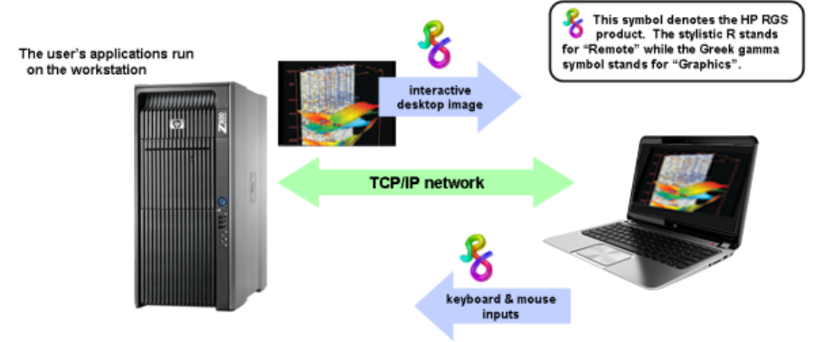
Typical RGS configuration
The following illustration shows a typical RGS configuration, consisting of a remote computer (sender)
and a local computer (receiver). In this example, the sender is the personal workstation on the left and
the receiver is the mobile workstation on the right. The user’s applications run on the sender while the
user interacts with these applications from the receiver.
Figure 1-1 Typical RGS configuration
The workstation image is transmitted over the network to the receiver, which displays the desktop image
locally in a window. RGS is designed to provide fast capture, compression, and transmission of the
desktop image over standard TCP/IP networks. RGS also captures user keyboard and mouse inputs
from the client and sends them over the network to the sender.
RGS also supports remote USB, which enables a user to connect USB devices to the receiver and have
the USB devices accessible by the sender. In addition, RGS supports remote audio, whereby audio
output from the applications is transported over the network for playback on the receiver.
Typical RGS configuration 3
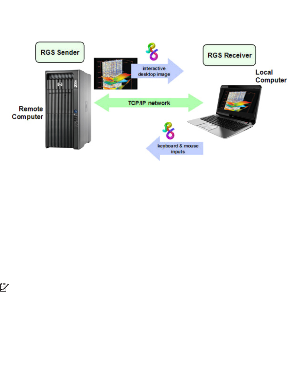
RGS Sender and Receiver
Figure 1-2 RGS Sender and Receiver on page 4 shows the two primary RGS software components,
the RGS Sender and RGS Receiver. The RGS Sender runs on the Remote Computer while the RGS
Receiver runs on the Local Computer.
Figure 1-2 RGS Sender and Receiver
The Sender and Receiver provide the following functionality:
●Sender—Runs on the Remote Computer, and transmits graphics updates, audio, and USB data to
the RGS Receiver on the Local Computer. The RGS Sender receives and processes keyboard
events, mouse events, and USB data from the Receiver.
●Receiver—Runs on the Local Computer. The RGS Receiver establishes a connection to the Remote
Computer, requests graphics updates from the Remote Computer Sender, and displays the desktop
of the Remote Computer inside a window on the Local Computer. The RGS Receiver transmits
keyboard and mouse events to the RGS Sender.
The RGS Sender captures the actual screen pixels that are generated by the graphics adapter on the
Remote Computer. This process is often referred to as screen scraping, and operates independently of
whether or not a monitor is actually connected to the Remote Computer.
NOTE: Local user refers to the person physically located at the Local Computer. Remote user refers to
the person physically located at the Remote Computer (if, in fact, a person is present at the Remote
Computer).
A local user who establishes an RGS login to the Remote Computer is known as the primary user. Once
a primary user has been established, another local user can view the Remote Computer desktop session
using RGS only if allowed by the primary user. There are situations, however, where a local user may
replace the previous primary user and become the new primary user.
The process by which a local user can become a primary user or view the primary user’s desktop is
described in detail in this guide.
4 Chapter 1 Introduction to HP Remote Graphics Software
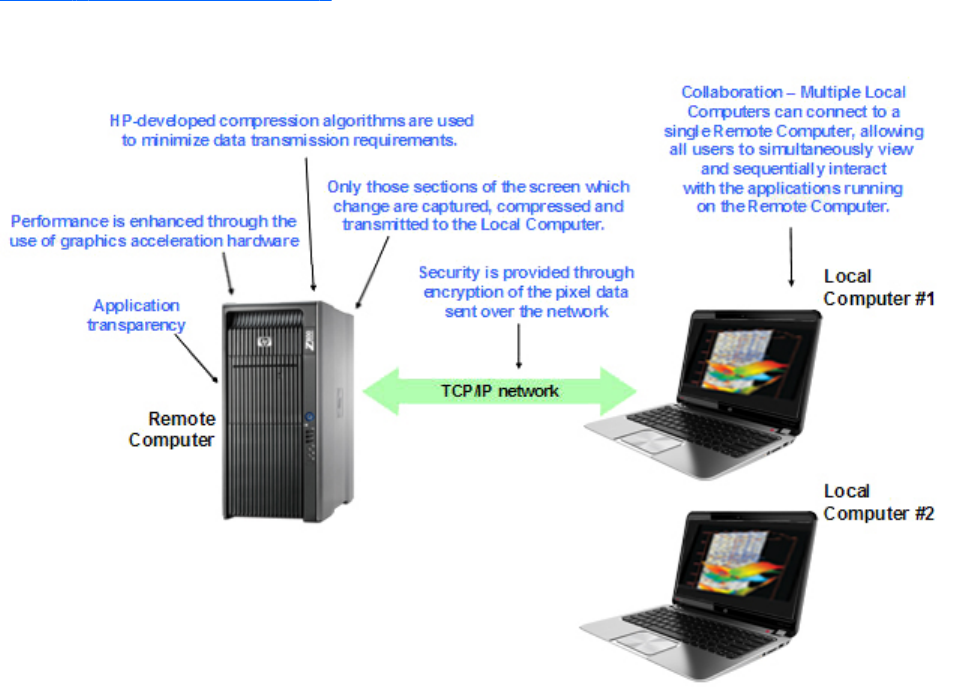
RGS features
RGS supports a number of features designed to optimize performance, security, and functionality (see
Figure 1-3 Features of RGS on page 5).
Figure 1-3 Features of RGS
●Application transparency—RGS supports application transparency, which enables
applications to be run on the Remote Computer, and accessed from the Local Computer, without
modifications.
●Graphics acceleration hardware—Performance is enhanced because the applications
running on the Remote Computer use its graphics acceleration hardware.
●HP compression/decompression algorithms—Proprietary, high-performance HP image
compression/decompression algorithms enable real-time remote visualization that is visually
lossless and highly interactive.
●Selective screen updates—Only those portions of the screen which change are captured,
compressed, and transmitted from the Remote Computer to the Local Computer, further improving
performance.
●Security—RGS supports many security features, including encryption of the pixel data sent from
the Remote Computer to the Local Computer.
●Collaboration—Multiple users can simultaneously connect to the same Remote Computer,
allowing the users to view and interact with the same desktop session and applications.
RGS features 5

Additional RGS features
RGS provides many additional features, including:
●3D application support—Users can interact with OpenGL 3D applications running on the
Remote Computer. Direct3D applications can be used as well, provided they are not in full-screen
mode. 3D applications use the full power of graphics acceleration hardware on the Remote
Computer.
●Remote USB—Many USB devices connected to the Local Computer can be attached to and
accessed by the Remote Computer. Some USB devices, such as web cams, are not supported.
●Remote Audio—Smooth, continuous, low-latency, high-quality remote audio is transmitted from
the RGS Sender to the RGS Receiver.
●Audio follows focus—In Directory Mode, the RGS Receiver can be configured to enable audio
for the session displayed in the Remote Display Window that currently has focus, and is muted for
all other remote sessions/windows.
●Directory Mode—Directory Mode enables the user to connect to multiple remote computers at
the same time. The remote computers are specified in a configuration file on the local computer.
●Easy Login—Enables fewer authentication steps when connecting to an HP personal workstation
running supported Windows operating systems or Linux distributions.
●Single Sign-on—Enables fewer authentication steps and automatic login and unlocking of the
desktop when connecting to an HP workstation running supported Windows operating systems.
●Interactive Experience Controls—Added at RGS 5.4.5, these controls allow the user to
adjust for a better interactive experience when operating across low bandwidth and/or high
latency networks.
●Windows Event Logging—Network outages or loss of connectivity between a Receiver and
Sender can leave a desktop session running without supervision. To safeguard running
applications, customer-designed agents can monitor the status of connections to determine if
termination of applications is required. Windows event logging provides a mechanism for agents
to determine the status of the connection between the Receiver and Sender.
NOTE: See the RGS 5.4.8 data sheet for latest list of features.
6 Chapter 1 Introduction to HP Remote Graphics Software

Tabloid-size page
The PDF version of this guide contains a tabloid-size page that is best viewed either on your computer
monitor or by printing it on size B (11 inches by 17 inches) or ISO A3 (297 mm by 420 mm) paper.
The tabloid page is included to permit a complex diagram (the diagram on the last page) to be
documented on a single page while maintaining readability.
The tabloid page from the PDF document may be printed individually if you have access to a tabloid-
capable printer. Go to the last page, select Current Page in the print dialog, and select Properties to
view the paper size and orientation options. Depending on your printer, paper size may be listed as
tabloid, size B, or size A3. Orientation should be set to landscape.
NOTE: The PDF version of the HP Remote Graphics Software Users Guide 5.4.8 can be found at:
http://www.hp.com/support/rgs_manuals
Obtaining HP technical support
If you encounter an issue that requires technical support, please do the following prior to contacting HP
for assistance:
●Be in front of the Local Computer or Remote Computer, whichever one is appropriate.
●Note the operating system.
●Note any applicable error messages.
●Note the applications you were using when you had the issue.
●Be prepared to spend the time necessary to troubleshoot the problem with the service technician.
For a listing of all worldwide technical support phone numbers, visit http://www.hp.com/support,
select your region, and click Contact HP in the upper-left corner.
NOTE: If your phone call is answered by a voice recognition system, and if you’re asked to provide
the name of the product, please say “Remote Graphics Software”, not “RGS”.
Tabloid-size page 7

Software service strategy for non-HP hardware
RGS 5.4.8 and later is designed for and compatible with the following Microsoft
®
Windows operating
systems on hosted OS Virtual Machine and physical machine environments:
●Windows
®
XP Professional 32- and 64-bit
●Windows 7 Professional and Enterprise 32- and 64-bit
●Red Hat Enterprise Linux V5 and V6.1 32- and 64-bit
●Suse Linux Enterprise Desktop V11 SP1 32- and 64-bit
Telephone support service is for RGS software installation and configuration support.
●Customer must have a fully functioning system with a standard Microsoft Windows operating
system (or one of the Linux operating systems supported—see list above) loaded and running
Software patch updates are available through Software Depot at http://software.hp.com under Client
Virtualization.
Other RGS documents
Other RGS documents such as the HP Remote Graphics Software Licensing Guide can be found at:
http://www.hp.com/support/rgs_manuals
8 Chapter 1 Introduction to HP Remote Graphics Software

2 RGS overview
Before exploring how to use RGS, it’s important to first understand the required system environments
and security features used and supported by RGS.
●Supported computers and operating systems on page 10
●RGS version numbering on page 12
●RGS licensing on page 14
●RGS products on page 15
●Sender and Receiver interoperability on page 15
●Application support on page 16
●Networking support on page 16
●Connection topologies on page 16
◦The Remote Computer frame buffer on page 16
◦One-to-one connection on page 17
◦Many-to-one connection on page 18
◦One-to-many connection on page 19
●Establishing an RGS connection using Standard Login on page 21
●Single Sign-on and Easy Login on page 23
●RGS operating modes on page 26
●Multi-monitor configurations on page 26
●Remote Computer monitor blanking overview on page 28
●Video overlay surfaces on page 28
●Image quality on page 29
●Remote USB overview on page 30
●Remote audio on page 38
●Remote Clipboard overview on page 45
9

●Interoperability of RGS and Microsoft Remote Desktop Connection on page 48
●Remote Computer power saving states on page 48
●Supported keyboard locales on page 49
●RGS security features on page 50
This chapter provides an overview of each of these features.
For a description of new features and other late-breaking topics, see the README.txt file in the
installation directory of either the RGS Receiver or RGS Sender. The file is best viewed using Wordpad,
Microsoft Word or Openoffice swriter.
Supported computers and operating systems
This section describes the computers and operating systems which support RGS 5.4.8. Any RGS 5.4.8
Sender can interoperate with any RGS 5.4.8 Receiver.
Table 2-1 Computers and operating systems that support RGS 5.4.8 Receiver
Receiver
Platforms
Windows XPe/
Windows
Embedded
Standard (WES
2009)/WES 7
Windows XP
Professional
SP1, SP2, SP3
32-bit, x64
Windows 7
Professional
and Enterprise
32-bit and 64-
bit
Embedded Linux RHEL V5.2 or
later; V6.2, 32-
bit, 64-bit
Desktops
Personal
Workstations*
X X HP xw and z
series
Mobile
Workstations*
XX
Desktop PCs X X
Notebook PCs X X
*NVIDIA Quadro and AMD FirePro graphics only
Thin Clients
HP t5740 WES 2009
HP t5740e WES 7
HP t5745 HP ThinPro
HP t610 WES 7, WES
2009
HP ThinPro
HP gt7720 WES 2009
HP gt7725 HP ThinPro
HP 6360t WES 7, WES
2009
10 Chapter 2 RGS overview

Table 2-2 Computers and operating systems that support RGS 5.4.8 Sender
Sender Platforms Windows XP
Professional SP1, SP2,
SP3 32-bit, x64
Windows 7 Professional
and Enterprise 32-bit
and 64-bit
RHEL V5.2 or later;
V6.2, 32-bit, 64-bit;
SLED 11, 32-bit, 64-bit
Blade Environments
HP Blade Workstations* X X X
VDI Servers X non-aero only X
*NVIDIA Quadro and AMD FirePro graphics only
Desktops
Personal Workstations* X X X
Mobile Workstations* X X
Desktop PCs X X
Notebook PCs X X
*NVIDIA Quadro and AMD FirePro graphics only
NOTE: Desktop Sender systems require 1.5 GHz or greater processor with SSE2 multi-media
instruction extension, 32-bit color display adapter, and 512 MB minimum RAM.
Windows 7 Aero theme desktop running on a Sender requires an NVIDIA graphics card and a
compatible NVIDIA driver that has native DX10 support. Windows 7 systems require driver version
191.56 and later.
In this document, references to “Windows” in the context of the RGS Sender refer to those Microsoft
operating systems in the foregoing tables that support the RGS Sender. Similarly, references to
“Windows” in the context of the RGS Receiver refer to those Microsoft operating systems in that support
the RGS Receiver.
Remote Graphics Software (RGS) is supported to the client OS level. As of the RGS 5.4.7 release (Oct
2011), the operating systems supported to the OS level are:
●Windows: Windows XP 32-bit, X64 and Windows 7 Professional 32-bit, 64-bit
●Linux: Red Hat Enterprise Linux Workstation Edition Release 5 Update 3+, RHEL 6 V1, and Suse
Linux Enterprise Desktop version 11.1 (may require specific versions of the kernel, xorg, and/or
xserver, in conjunction with the supported Linux distributions)
HP will attempt to reproduce the customer reported issue on an HP Deskside Workstation or other HP
system specified in the official support matrix provided with RGS documents, with the OS image that
HP factory installs (or formally supported) on that HP system. If HP can reproduce the behavior per this
structure, the issue will be handled per standard process. If HP cannot reproduce the behavior per this
structure then the issue must be addressed between the customer and the hardware platform provider.
NOTE: HP may require the customer to use specific versions of the kernel, xorg, and/or xserver, in
conjunction with the supported Linux distributions.
For more information on HP products, please visit http://www.hp.com/support
Supported computers and operating systems 11

RGS support requirements
Table 2-3 RGS support requirements
Operating System Bare Metal Citrix XenServer
v6
VMWare vSphere
(ESX) v5.0
Microsoft Hyper-
V
ws460 G6 BWS
Microsoft Windows XP 32-bit
SP3
Supported Supported Supported Not supported
Microsoft Windows XP 64-bit
SP3
Supported Supported Supported Not supported
Microsoft Win7 32-bit SP1 Supported Supported Supported Not supported
Microsoft Win7 64-bit SP1 Supported Supported Supported Not supported
Microsoft Server 2008 R2 SP1 Not supported Not supported Not supported Not supported
HP version of Red Hat Enterprise
Linux v5/6 (WS & Server
treated as identical)
Supported Supported Supported Not supported
Suse Linux Enterprise Server
v11, SP1
Not supported Supported Supported Not supported
SL250 server w/M2070Q GPU compute cards
Microsoft Windows XP 32-bit
SP3
Not supported Not supported Not supported Not supported
Microsoft Windows XP 64-bit
SP3
Not supported Not supported Not supported Not supported
Microsoft Win7 32-bit SP1 Not supported Not supported Not supported Not supported
Microsoft Win7 64-bit SP1 Not supported Not supported Not supported Not supported
Microsoft Server 2008 R2 SP1 Not supported Not supported Not supported Not supported
HP version of Red Hat Enterprise
Linux v5/6 (WS & Server
treated as identical)
Supported Not supported Not supported Not supported
Suse Linux Enterprise Server
v11, SP1
Supported Not supported Not supported Not supported
RGS version numbering
The RGS version (for example, version 5.4.0) contains the following three numbers:
1. Version major number
2. Version minor number
3. Version patch number
12 Chapter 2 RGS overview
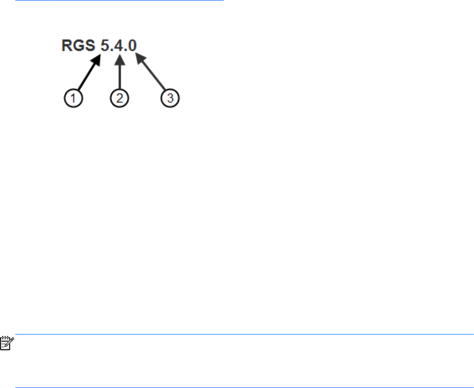
Figure 2-1 RGS version numbering on page 13 shows the positioning of the three version numbers.
Figure 2-1 RGS version numbering
RGS version description
1. Major – A major release contains sufficient changes such that interoperability with the prior
primary release is not guaranteed. For example, Sender version 5.4.0 is not guaranteed to
interoperate with Receiver version 4.2.0. A major release introduces significant new RGS features
and functionality. They will also include (roll up) the changes in any prior minor and patch
releases.
2. Minor – A minor release is generated for minor features, a security issue, or for a major defect in
a feature. A minor release is indicated by this number being non-zero. Therefore, RGS 5.4 is a
minor release.
3. Patch – A patch release is generated for issues such as bug fixes and security issues. A patch
release is indicated by this number being non-zero. Therefore, RGS 5.4.0 is not a patch release.
RGS 5.4.5 would be a patch release.
NOTE: Each patch release is a complete release of the entire RGS product, regardless of what
components have changed. For example, if a patch release is needed to make an RGS Sender security
fix available, the entire RGS product (including both the RGS Sender and Receiver) would be included
in the patch release.
RGS version numbering 13
RGS licensing
NOTE: RGS licensing applies to the RGS Sender only. The RGS Receiver is a free download and can
be used on any number of computers. Therefore, the following discussion of RGS licensing applies only
to the RGS Sender. For detailed information on RGS licensing, see the HP Remote Graphics Software
Licensing Guide, available at http://www.hp.com/support/rgs_manuals.
Two types of licenses are supported by the RGS Sender:
1. Local license file—With local licenses, each system running the RGS Sender requires a license file.
◦A license must be purchased and the license file installed for each RGS Sender computer.
2. Multi-user licenses—With multi-user licenses, a pool of RGS licenses is purchased, which are
dynamically allocated on a first-come, first-serve basis whenever an RGS Receiver first attempts to
connect to an RGS Sender. In licensing terminology, a multi-user license is checked-out when a
connection is established to the RGS Sender, and is checked-in when the connection terminates.
Multi-user licenses allow a company to purchase, for example, 75 licenses but support a user
community of perhaps hundreds of users as long as no more than 75 users ever attempt to
establish an RGS connection simultaneously.
Multi-user licenses require a license server, which can be installed on one of the computers
running the RGS Sender, or the license server can be installed on a separate computer. The RGS
product includes a setup.exe file that installs the license server—see the HP Remote Graphics
Software Licensing Guide, available at http://www.hp.com/support/rgs_manuals.
Prior to installing the RGS Sender license, you can still establish a connection from the Local Computer
to the Remote Computer, and can interact with the Remote Computer desktop. However, in the absence
of a license, the dialog shown in Figure 2-2 Dialog generated when the RGS Sender is unlicensed
on page 14 will be generated by the Remote Computer, and displayed in the window on the Local
Computer that is showing the Remote Computer desktop.
Figure 2-2 Dialog generated when the RGS Sender is unlicensed
Once the RGS Sender is licensed, the above dialog will no longer be displayed.
Users who need to deploy the RGS FlexNet license server on Linux may do so on RHEL v5 and v6 and
on SLED v11.
14 Chapter 2 RGS overview

RGS products
HP offers these RGS products :
1. HP RGS Desktop Trial Edition — HP offers a free, 60-day trial version of RGS Desktop; no
license purchase is required.
2. HP RGS VDI local license — This RGS product runs on Citrix XenDesktop and VMware VDI
(Virtual Desktop Infrastructure) platforms. RGS VDI uses a local license file key. A separate RGS
VDI license is required for each virtual machine using RGS.
3. HP RGS Desktop local license — This RGS product runs on all RGS supported platforms,
including: notebooks, desktop PCs, mobile workstations, personal workstations and HP blade
workstations. In addition, this key will also run on VMware VDI platforms that are supported by the
RGS VDI license key.
4. HP RGS Desktop multi-user license — This RGS product runs on all RGS supported
platforms, including: notebooks, desktop PCs, mobile workstations, personal workstations and HP
blade workstations. In addition, this key will also run on VMware VDI platforms that are supported
by the RGS VDI license key.
All RGS products include the same RGS Sender and the same RGS Receiver. The RGS Receiver is
unlicensed and can be installed on any number of computers.
NOTE: Except for the 60-day HP RGS Desktop Trial Edition, the above RGS products never
expire once they are installed and licensed.
When you purchase RGS, you are entitled to free upgrades to all future patch releases. For example, if
you purchase RGS 5.4.8, you are entitled to a free upgrade to patch release 5.4.9, if available.
Upgrade pricing is available for new major releases of RGS. To qualify for upgrade pricing, you must
be a licensed owner of a qualifying version of RGS. The previous two versions of RGS qualify for
upgrade pricing. For example, versions 5.4 and 5.3 both qualify for upgrade pricing for the next
major release of RGS.
For more detailed information on the RGS products, see the HP Remote Graphics Software QuickSpec
available on the RGS homepage at http://www.hp.com/go/rgs.
Sender and Receiver interoperability
RGS provides interoperability between versions of RGS Senders and Receivers that have the same
major version number. For example, Sender version 5.0 and Receiver version 5.1 will interoperate
together. However, Sender version 4.2 is not guaranteed to interoperate with Receiver version 5.0.
Connection between a Receiver and a Sender should only be attempted when their major version
numbers are the same. Beginning with RGS 5.4.0, the Windows 7 Sender added the capability to
notify the Receiver prior to shutting down. The Windows 7 Sender must exit and then restart under
several conditions such as: login, logoff, or Microsoft Remote Desktop Connection (RDC) transition. This
behavior allows the Receiver to reconnect after the Sender has restarted. Receivers prior to 5.3.0 will
show a pink or black screen and then a Reconnect dialog box if the Sender has exited.
RGS products 15

Application support
RGS supports all applications, except those applications that use full screen exclusive mode. RGS may
not be suitable for most full screen games. If a full-screen MS-DOS command prompt window is created
on the Sender (using, for example, command.com), the window will be reset to its default size by RGS.
Likewise, if a full-screen Windows XP Professional command prompt window is created (using cmd.exe
or the command prompt icon), the window will also be reset to its default size by RGS. Full-screen
DirectDraw applications are not supported (however, DirectDraw applications in a Window may work,
and should be qualified individually).
On Remote Computers running Linux, OpenGL-based applications can only be remoted if the Remote
Computer is using NVIDIA graphics.
RGS 5.2.6 and newer Sender and Receiver executables are signed for compatibility with strict anti-
virus programs.
Networking support
RGS uses TCP/IP over a standard computer network, and supports Ethernet connection speeds of
10/100/1000BASE-T (Gigabit). The RGS Sender listens on TCP/IP port 42966. The port used by the
RGS Receiver is assigned by the Local Computer OS and can vary. HP recommends full-duplex
operation between the Sender and Receiver. For information on using RGS through a firewall, see
Using RGS through a firewall on page 98.
Beginning in RGS 5.4.0, the Sender defaults to “listening” to all available network interfaces. The
Sender also has the ability to dynamically add or remove network interfaces and update IP address
changes of a network interface while there are no active RGS connections. If there are one or more
active RGS sessions, the Sender will update the network interface bindings after the connections are
disconnected. For instance, if an additional network interface is enabled and configured, the Sender
will add that network interface to the binding list and begin listening on that network interface for
connect requests. If the IP address of a network interface changes due to a DHCP change for instance,
the Sender will update the network interface binding. The Sender does not have to be restarted as with
previous versions of RGS to update network interface bindings.
NOTE: At RGS 5.2.5, the capability was added to specify the port number used by the RGS Sender.
The default Sender port number is 42966, as noted above. The Sender port number can be changed
using the Rgsender.Network.Port property. If this property is used to change the Sender port number
from its default value of 42966, the Sender port number must then be specified in establishing an RGS
connection from the Receiver to the Sender.
Connection topologies
This section describes the connection topologies supported by RGS, such as how a single Local
Computer may connect to multiple Remote Computers.
The Remote Computer frame buffer
After making a connection between a Local Computer and a Remote Computer, the Remote Computer
Sender transmits its complete frame buffer to the Local Computer. The frame buffer is the memory on the
16 Chapter 2 RGS overview
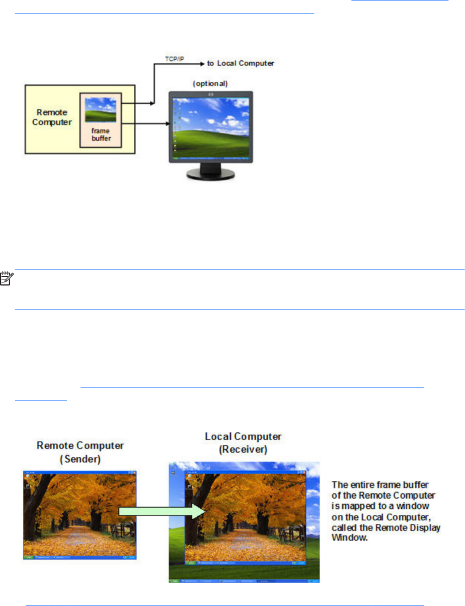
Remote Computer video adapter that holds the bitmapped image that is typically displayed on a
monitor—the frame buffer below contains the familiar Windows desktop (see Figure 2-3 The Remote
Computer frame buffer containing the Windows desktop on page 17).
Figure 2-3 The Remote Computer frame buffer containing the Windows desktop
The monitor itself is optional on the Remote Computer. For example, if the Remote Computer is a
Personal Workstation, a monitor (plus a keyboard and mouse) would typically be attached. If the
Remote Computer is an HP ProLiant Blade Workstation, it is not possible to attach a monitor to view the
primary (NVIDIA) frame buffer because the video signal from the NVIDIA graphics adapter is not
available on a connector—the contents of the frame buffer can only be viewed remotely using RGS.
NOTE: For clarity in this guide, the bitmapped image contained in the Remote Computer frame buffer
will often be shown in association with the Remote Computer, independent of whether a monitor is
actually connected (or can be connected) to the Remote Computer.
One-to-one connection
The simplest RGS connection is a single Local Computer making a connection to a single Remote
Computer. The entire frame buffer of the Remote Computer is displayed in a window on the Local
Computer (see Figure 2-4 Display of the Remote Computer frame buffer on the Local Computer
on page 17). The window on the Local Computer is called the Remote Display Window.
Figure 2-4 Display of the Remote Computer frame buffer on the Local Computer
In Figure 2-4 Display of the Remote Computer frame buffer on the Local Computer on page 17, the
Remote Computer frame buffer fits completely within the Remote Display Window on the Local
Computer monitor. However, it is possible for the Remote Computer frame buffer size to exceed the
Connection topologies 17
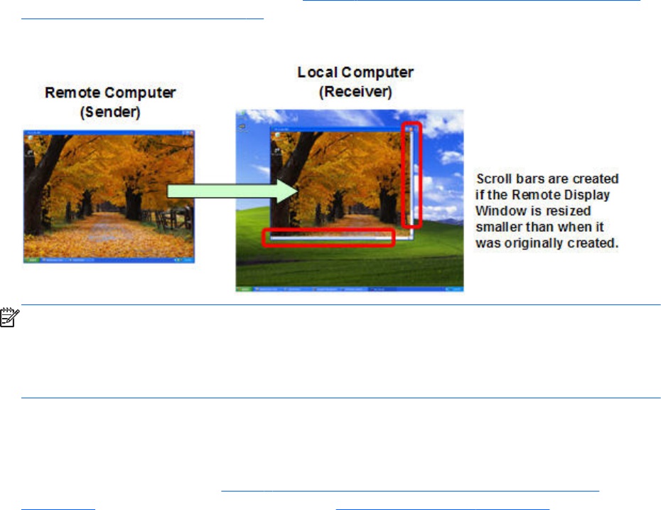
size of the Local Computer monitor (as measured in horizontal pixels by vertical pixels). As before, the
Remote Display Window will be the size of the Remote Computer frame buffer. If the Remote Display
Window is larger than the Local Computer monitor, the window will extend off the monitor.
Regardless of the size of the Remote Display Window (that is, whether it fits on the Local Computer
monitor or extends off the monitor), if the local user resizes the Remote Display Window to be smaller
than when it was originally created, scroll bars will be added to allow the local user to view the
complete Remote Computer frame buffer (see Figure 2-5 Addition of scroll bars if the Remote Display
Window is resized smaller on page 18).
Figure 2-5 Addition of scroll bars if the Remote Display Window is resized smaller
NOTE: RGS does not provide a scale-to-fit capability to allow the contents of the Remote Computer
frame buffer to be scaled to fit the Local Computer monitor. If the Remote Computer frame buffer is
larger than the Local Computer monitor, the Remote Display Window will simply extend beyond the
edges of the monitor. If the Remote Display Window is resized to fit on the monitor, scroll bars will be
added.
Many-to-one connection
The RGS Receiver supports a many-to-one connection, allowing a single Local Computer to connect to
multiple Remote Computers (see Figure 2-6 A Local Computer displaying two desktop sessions
on page 19) each running a desktop session—see RGS operating modes on page 26, specifically
18 Chapter 2 RGS overview
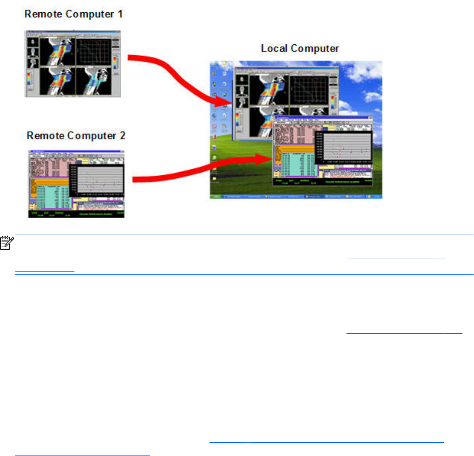
Directory Mode. The frame buffer of each Remote Computer is displayed in a separate Remote
Display Window on the Local Computer.
Figure 2-6 A Local Computer displaying two desktop sessions
NOTE: Starting up two (or more) instances of the RGS Receiver to achieve a many-to-one connection
is not supported. Achieving a many-to-one connection is only supported by Using Directory Mode
on page 170 .
The many-to-one connection capability allows implementation of a virtual KVM (keyboard, video, and
mouse) switch. The virtual KVM switch emulates the functionality of a standard KVM switch in software
to provide a convenient method to connect a single monitor, keyboard, and mouse (all on the Local
Computer) to multiple Remote Computers. Using the RGS Setup Mode (see Setup Mode on page 104)
you can switch the local monitor to display each of the Remote Computer frame buffers. The Receiver
can also switch audio between active sessions as described in the Controlling Receiver Settings section
using the audio follows focus option.
One-to-many connection
RGS also supports a one-to-many connection, allowing the frame buffer of a Remote Computer to be
displayed on multiple Local Computers (see Figure 2-7 Multiple users can access the desktop of a
Remote Computer on page 20). In this figure, there is one primary user who is logged into the
Connection topologies 19
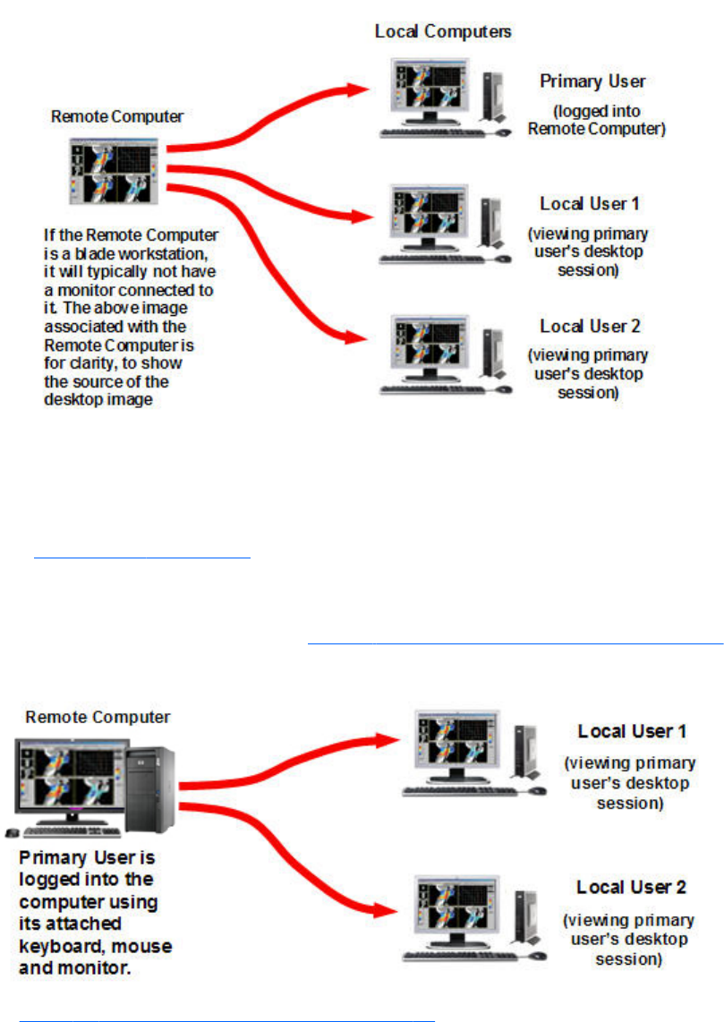
Remote Computer, and two local users who are viewing the primary user’s desktop session on the
Remote Computer.
Figure 2-7 Multiple users can access the desktop of a Remote Computer
The one-to-many configuration is ideal for collaboration because each user can interact with the
applications running on the Remote Computer (subject to RGS policies which arbitrate which user is
able to provide keyboard and mouse inputs to the Remote Computer at any particular time). As one
user interacts with the applications on the Remote Computer, all other users can view these interactions.
See Collaborating on page 114, for details.
In the previous example, it was assumed that the primary user and the local users were all physically
separate from the Remote Computer. This, however, doesn’t have to be the case. RGS works equally
well sharing between workstations (see Figure 2-8 Sharing between workstations on page 20).
Figure 2-8 Sharing between workstations
In Figure 2-8 Sharing between workstations on page 20, the primary user is directly logged into the
Remote Computer using its attached keyboard, mouse and monitor. In other words, the primary user is
physically present at the Remote Computer, while local user 1 and local user 2 are physically separate
20 Chapter 2 RGS overview
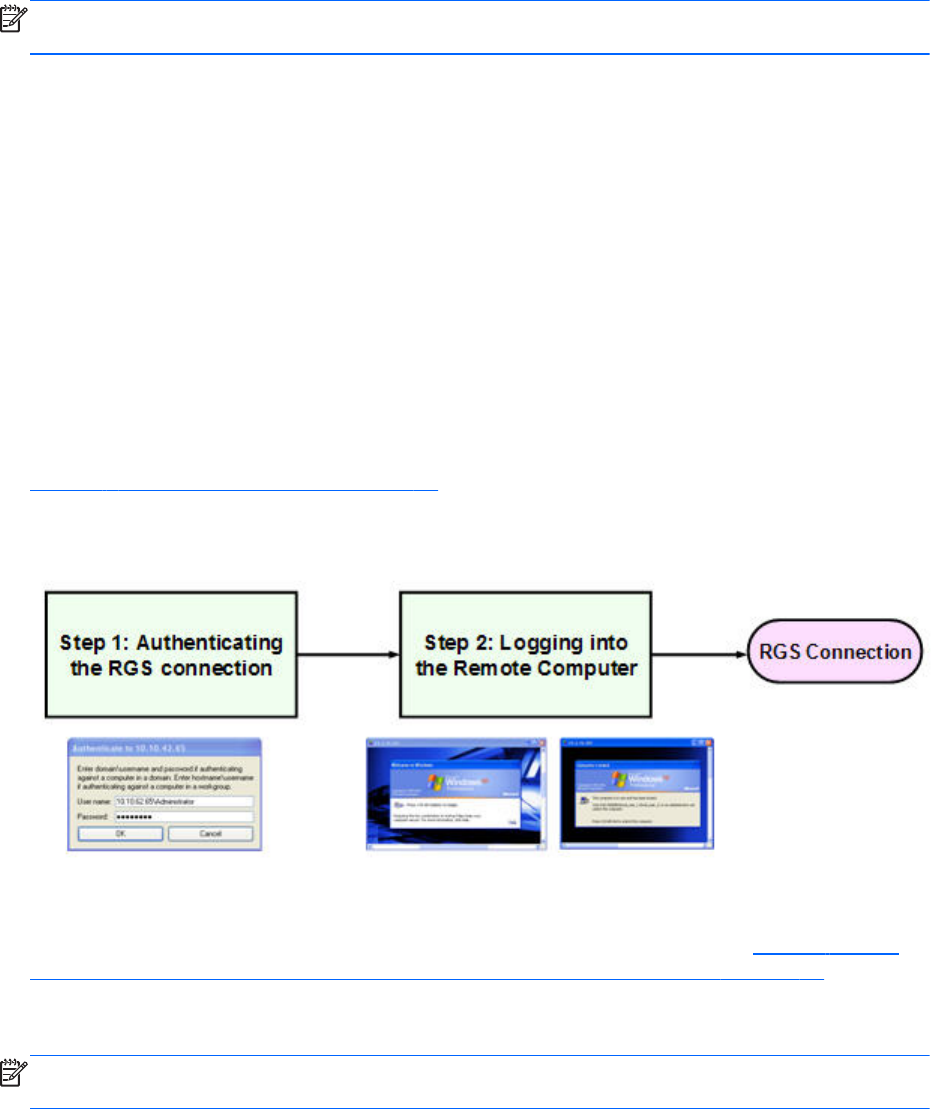
from the Remote Computer. RGS can be used by local users 1 and 2 to connect to the primary user’s
desktop.
NOTE: One-to-many (collaboration) requires a unique login account with credentials on the sender
for each participant.
Establishing an RGS connection using Standard
Login
In normal operation, users are required to authenticate twice when establishing an RGS connection
from a Local Computer to a Remote Computer. This is the Standard Login process—the two steps are:
1. The first authentication step is from the RGS Receiver to the RGS Sender— this is called
authenticating the RGS connection. The dialog for this authentication step is generated and
displayed by the RGS Receiver on the Local Computer.
2. The second authentication step is when logging into or unlocking the Remote Computer desktop
session— this is called logging into the Remote Computer. The login or unlock dialog is generated
by the Remote Computer, and is displayed in the Remote Display Window on the Local Computer.
Figure 2-9 Standard Login process on page 21 shows the two-step Standard Login RGS
connection process.
Figure 2-9 Standard Login process
If another user is already logged into the Remote Computer, the second authentication step is replaced
by an authorization step, in which the currently logged-in user receives an authorization prompt to
allow or disallow the new user to join (connect to) the existing desktop session (see Figure 2-10 RGS
connection process if another user is already logged into the Remote Computer on page 22). The
new user is allowed to connect to the existing RGS connection only if the currently logged-in user
authorizes the connection.
NOTE: One-to-many (collaboration) requires a unique login account with credentials on the sender
for each participant.
Establishing an RGS connection using Standard Login 21
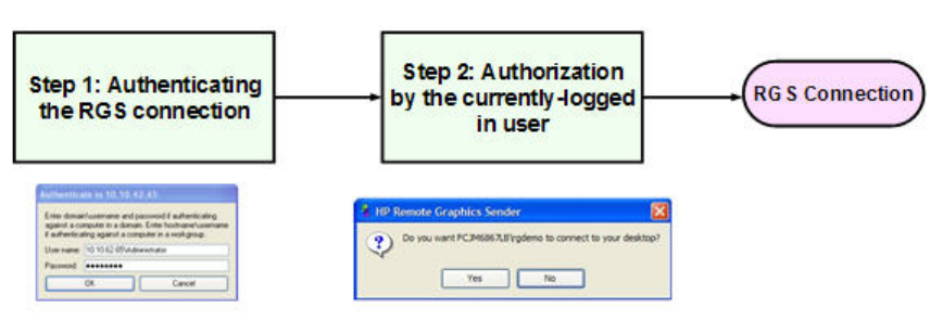
Figure 2-10 RGS connection process if another user is already logged into the Remote Computer
There are a number of variations of the Standard Login process, as detailed in the diagram of the
Standard login process on the tabloid page (the last page of the PDF version) of this guide.
22 Chapter 2 RGS overview
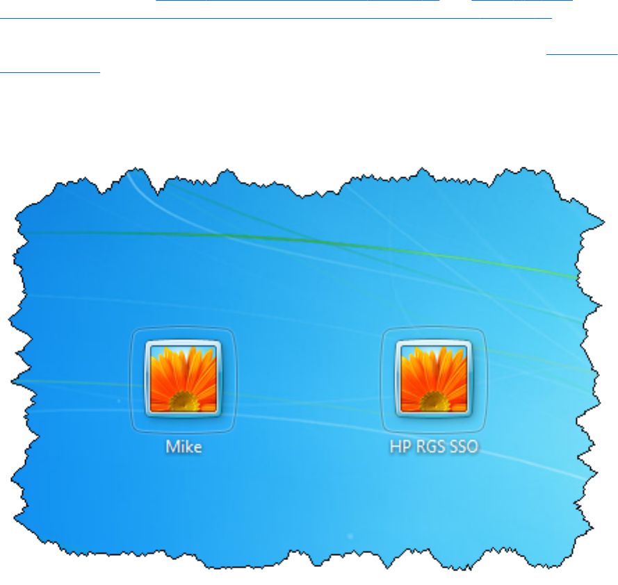
Single Sign-on and Easy Login
RGS supports two additional login methods in certain circumstances. These two methods allow users to
enter their credentials only once in connecting to a Remote Computer—these methods are described
below, along with which authentication process is used:
Single Sign-on
Single Sign-on—Supported only for Windows-based senders. The RGS connection authentication
process is used (step 1 in Figure 2-9 Standard Login process on page 21 and Figure 2-10 RGS
connection process if another user is already logged into the Remote Computer on page 22). If
authentication is successful, the user will immediately see the Windows desktop session without needing
to explicitly log into Windows or unlock the desktop. Single Sign-on is described further in Single Sign-
on on page 112.
If the user “Locks” the screen on Windows 7, a screen like the following is displayed. The user must
click the “user” tile to log in, not the RGS SSO tile
Figure 2-11 Locked remote screen with Single Sign-on and Windows 7
Easy Login
Easy Login—Supported on Windows- and Linux-based senders. The user is pre-connected to the
system and standard Windows or Linux login screens are used to login to the desktop or unlock the
screen. If authentication is successful, the user will immediately see the desktop session without needing
Single Sign-on and Easy Login 23

to be first authenticated by the RGS Receiver/Sender. Easy Login is described further in Easy Login
on page 111.
Deciding between Single Sign-on and Easy Login
If neither Single Sign-on nor Easy Login is selected, the default Standard Login will be used. In terms of
selecting between Single Sign-on and Easy Login, two factors to consider are:
●Windows XP Professional
Easy Login on Windows XP Professional supports GINA (Graphical Identification and
Authentication) chaining, allowing custom 3rd party login mechanisms to be integrated into RGS.
Single Sign-on does not support chaining of 3rd party GINA modules.
For example, a 3rd party fingerprint reader will typically install a custom GINA module. The
GINA module will allow the user to be authenticated through their standard username/password
mechanism (because the GINA modules are chaining) or with their fingerprint. The fingerprint
reader would be physically attached to the Local Computer but would be logically connected to
the Remote Computer using remote USB. If Easy Login is used, only a single login step is required
—the fingerprint reader will provide the credentials for logging into the Remote Computer.
24 Chapter 2 RGS overview
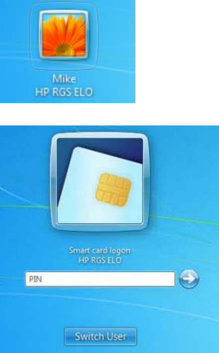
●Windows 7
Easy Login on Windows 7 uses Credential Providers to allow the user to be authenticated through
their standard username/password mechanism or using smart card or activkey technologies.
Single Sign-on does not support smart card or activkey technologies. The only Credential Providers
supported when using Easy Login are the Microsoft Password Credential Provider and the
Microsoft Smartcard Credential Provider.
For example if a smart card or activkey is not connected to the system, the user will be
authenticated through their standard username/password mechanism. However if a smart card or
activkey is connected to the system, Easy Login will use that device to authenticate the user.
Figure 2-12 Easy Login username/password tile example
Figure 2-13 Easy Login smart card tile example
●Linux
Easy Login is supported on Linux-based senders. Single Sign On is not supported on Linux-based
senders.
Single Sign-on and Easy Login 25
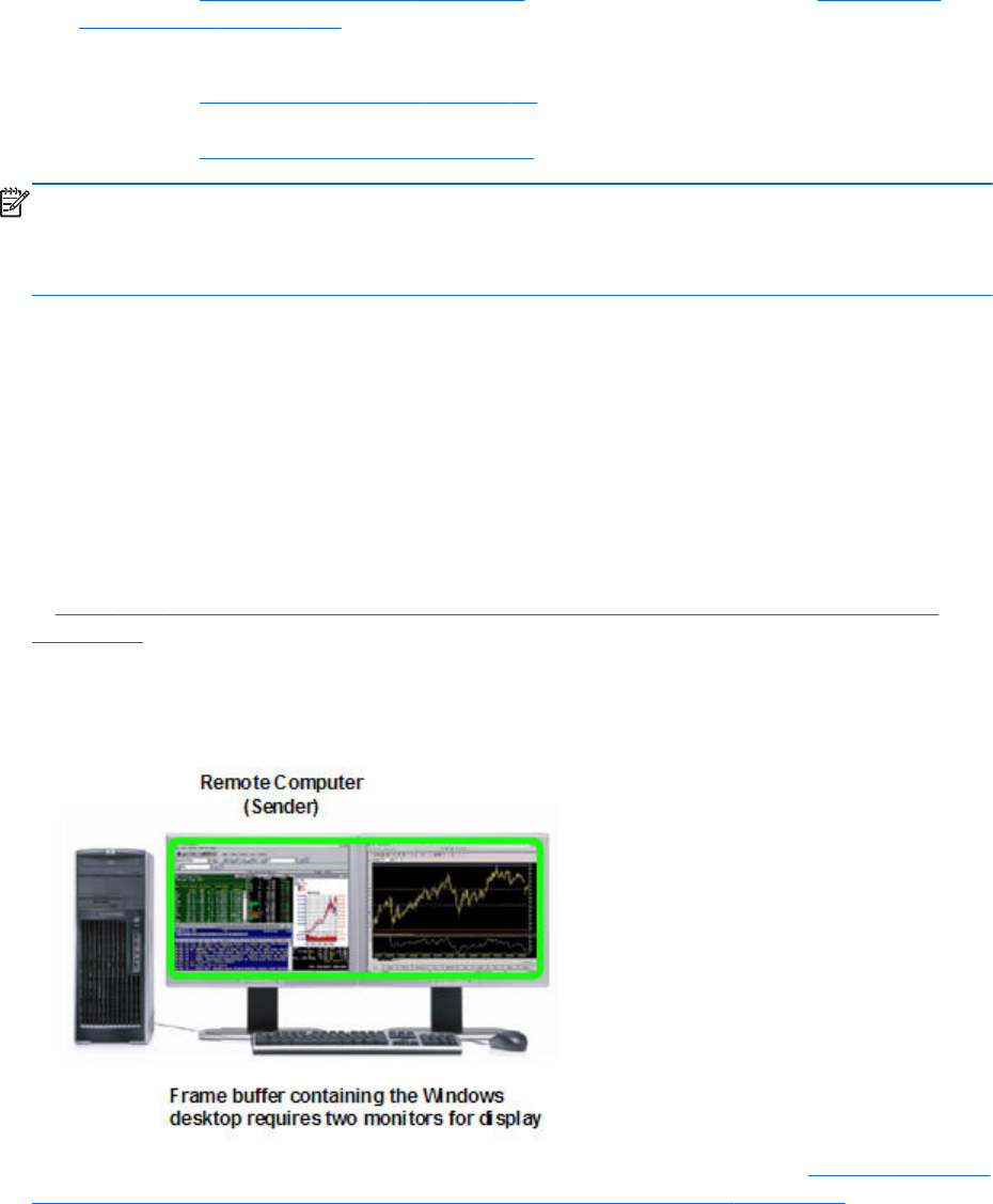
RGS operating modes
RGS supports two basic operating modes:
1. Normal Mode — This mode enables RGS to connect to a single Remote Computer, as
described in One-to-one connection on page 17, Normal Mode is described in Using RGS in
Normal Mode on page 101.
2. Directory Mode — This mode enables RGS to connect to multiple Remote Computers, as
described in Many-to-one connection on page 18. Directory Mode is based on a user-created file
which specifies which Remote Computers the RGS Receiver should connect to. Directory Mode is
described in Using Directory Mode on page 170.
NOTE: Prior to RGS 5.2.0, RGS supported a third operating mode—Enterprise Service Mode.
Enterprise Service Mode was based on the creation of a network service which specified which Remote
Computers the RGS Receiver should connect to. Enterprise Service Mode has been superseded by HP
Session Allocation Manager (SAM), and therefore has been discontinued as of the RGS 5.2.0 release.
Multi-monitor configurations
Many computers have a frame buffer that is larger in size (as measured in horizontal pixels by vertical
pixels) than what can be displayed on a single monitor. In these situations, the default operation is that
a portion of the frame buffer is used, allowing the utilized portion (containing the Windows desktop) to
be displayed on a single monitor. It is possible, however, to configure a computer so that the Windows
desktop occupies the complete frame buffer—this typically requires multiple monitors to view the
complete frame buffer (Windows desktop).
In Figure 2-14 Remote Computer frame buffer requires two monitors to view the Windows desktop
on page 26, the Windows desktop is configured to occupy the complete frame buffer of the Remote
Computer, which, for this particular Remote Computer, requires two monitors to display the Windows
desktop.
Figure 2-14 Remote Computer frame buffer requires two monitors to view the Windows desktop
When a Local Computer establishes an RGS connection to the Remote Computer of Figure 2-14 Remote
Computer frame buffer requires two monitors to view the Windows desktop on page 26, the Remote
Computer will transmit its complete frame buffer. In order for the local user to view the complete
26 Chapter 2 RGS overview
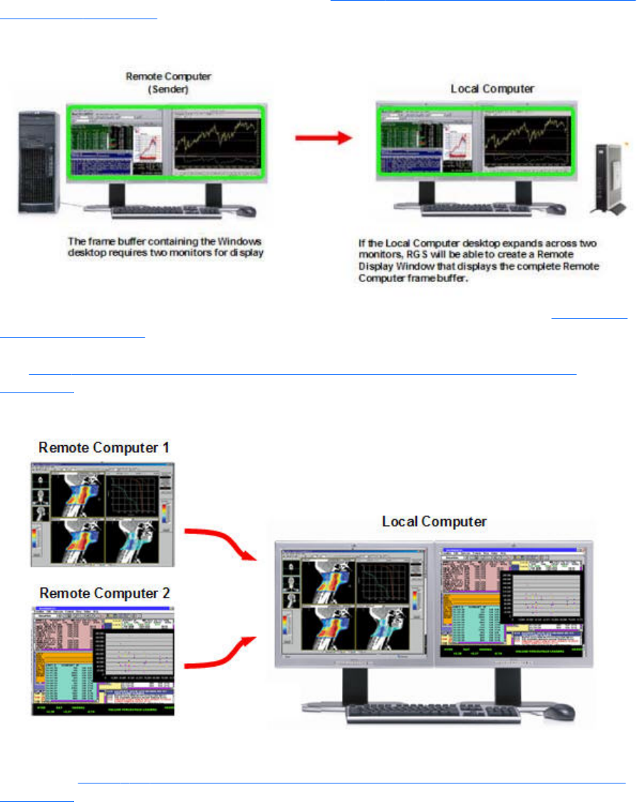
desktop of the Remote Computer, the Local Computer must have a comparably-sized frame buffer,
which will typically require two monitors to view (see Figure 2-15 A Remote Display Window spanning
two monitors on page 27).
Figure 2-15 A Remote Display Window spanning two monitors
Multiple monitors on the Local Computer are also useful in the configuration described in Many-to-one
connection on page 18. If the Local Computer is connected to two Remote Computers, each Remote
Computer frame buffer can be displayed on its own monitor if the Local Computer has two monitors
(see Figure 2-16 Each Remote Display Window can be positioned to occupy a single monitor
on page 27).
Figure 2-16 Each Remote Display Window can be positioned to occupy a single monitor
As always, each Remote Computer (Sender) frame buffer is displayed in its own Remote Display
Window. In Figure 2-16 Each Remote Display Window can be positioned to occupy a single monitor
on page 27, the user has positioned each Remote Display Window to occupy a single monitor,
achieving the result that the left monitor is dedicated to Remote Computer 1 while the right monitor is
dedicated to Remote Computer 2.
Multi-monitor configurations 27

Remote Computer monitor blanking overview
New in RGS 5.0, this feature blanks the Remote Computer monitor (if one is connected) when the local
user establishes an RGS connection to the Remote Computer and logs in—in other words, becomes the
primary user. This feature is provided for security, to ensure that the primary user’s desktop session on
the Remote Computer is not visible on a monitor connected to the Remote Computer. For details on
monitor blanking, see Remote Computer monitor blanking operation on page 107.
Video overlay surfaces
When the Windows Sender is installed on a computer, video overlay surfaces (also known as overlay
planes) are disabled on the computer. Some media players that use video overlay surfaces will not
display correctly. This can often be resolved by disabling the use of video overlay surfaces in the media
player.
Most OpenGL applications will detect the disabling of overlay surfaces, and will work correctly.
However, if your OpenGL application attempts to use the disabled overlay surfaces, it may display
incorrectly. If this is the case, check to see if your OpenGL application provides a mechanism for the
user to manually disable the use of overlay surfaces.
28 Chapter 2 RGS overview
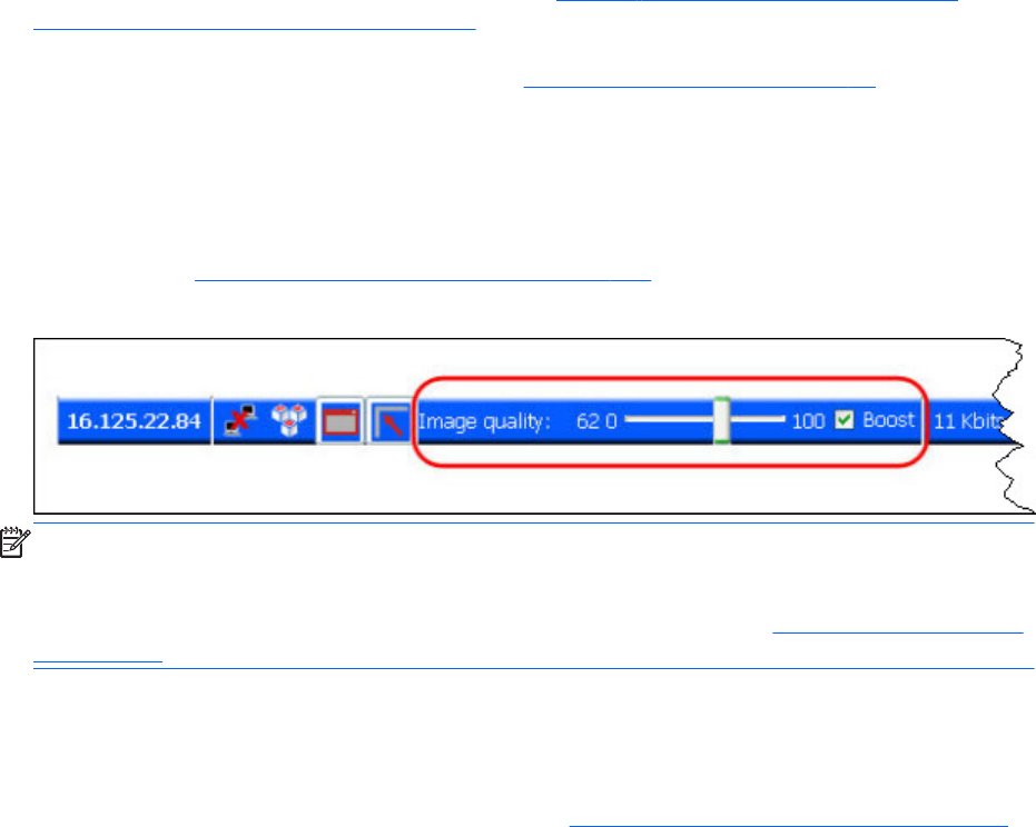
Image quality
RGS provides high-quality, high-performance image compression and decompression. Image
compression is performed on the Remote Computer to reduce the network bandwidth requirements—
this enables RGS to be used on standard networks. Image decompression is performed on the Local
Computer.
RGS supports setting of the Image quality on a per-Receiver basis. Image quality is adjusted using the
slide bar in the Remote Display Window Toolbar (see Figure 2-17 Image quality slide bar in the
Remote Display Window Toolbar on page 29). As the image quality is increased toward 100, the
amount of compression decreases, and the required network bandwidth increases. If a Receiver is
supporting multiple Remote Display Windows (see Many-to-one connection on page 18) the slide bar in
any Remote Display Window Toolbar can be adjusted—the slide bars in the other Remote Display
Windows will automatically track.
The Boost checkbox was added beginning with RGS 5.2.6, and requires that both the RGS Sender and
Receiver be version 5.2.6 or later. Checking the Boost checkbox will improve (boost) image quality for
certain types of images, primarily images containing significant amounts of text or lines. For further
information, see Remote Display Window Toolbar on page 106 .
Figure 2-17 Image quality slide bar in the Remote Display Window Toolbar
NOTE: Even with an image quality of 100, RGS still performs some image compression to reduce the
network bandwidth requirements. While the image quality on the Receiver will usually appear visually
lossless to the user, the actual image data sent over the network will be “lossy” to a limited extent. The
exception is the Sender codec JPEG-LS which is mathematically lossless. See Sender general properties
on page 200 for more information.
Beginning in RGS 5.4.5, the image quality slider control and Boost check box have been duplicated in
the Receiver Advanced > General tab under the Experience area. These controls are
synchronized with the controls in the Remote Display Window Toolbar. The added quality slider
and Boost check box provide a convenient location for the user to adjust best desired image quality
while adjusting the Interactive Experience controls. See General tab Experience section on page 120
for more details.
Image quality 29
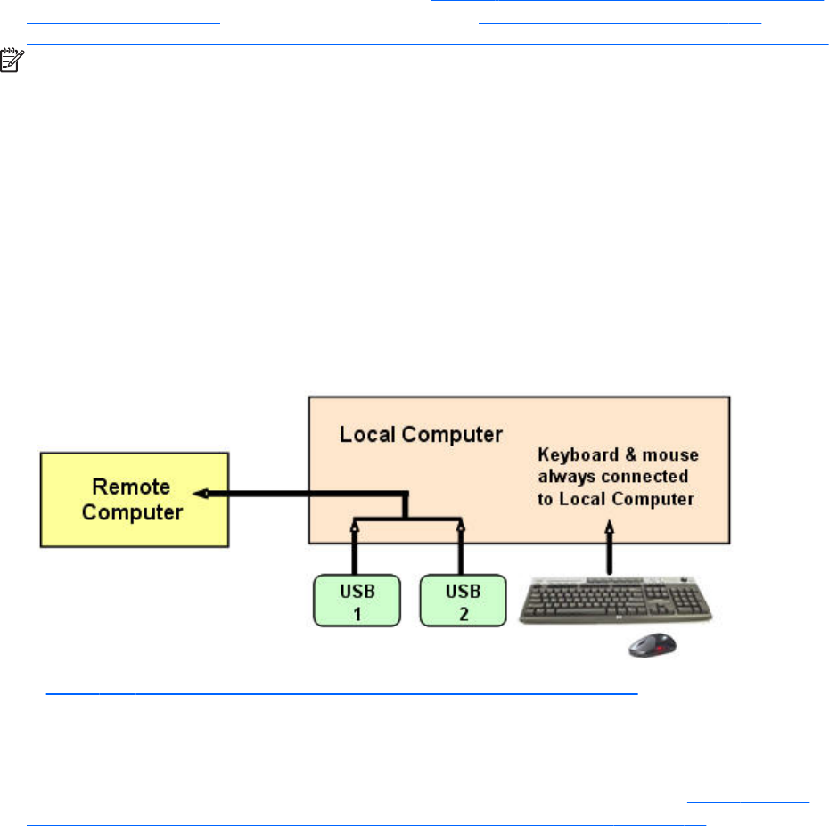
Remote USB overview
RGS supports remote USB, which allows USB devices connected to the Local Computer (local USB
devices) to be attached to a Remote Computer. Remote USB is supported on Remote Computers running
Windows, and enables the Remote Computer to have direct access to the local USB devices as if they
are connected directly to the Remote Computer (see Figure 2-18 Remote Computer can access the local
USB devices on page 30). For details on remote USB, see Remote USB operation on page 136.
NOTE: Hewlett-Packard RGS supports remote USB. Devices that adhere to the USB standard should
work. Because RGS is a remote graphics protocol and is emulating the USB protocol over a network,
devices that are sensitive to timing may not work at all. This includes USB devices with security and
encryption mechanisms built into them. The additional network delay could be looked at as a threat.
Other devices that are known to break the USB standard, such as WEB CAMS, may also not function
at all. Performance of USB devices over RGS will not be equal to that of a locally connected device.
File copies may take longer due to the additional overhead of the network protocol sitting on top of the
USB protocol.
HP recommends that customers thoroughly test any USB device they are considering to use with RGS as
Hewlett-Packard cannot certify and or guarantee it will work over a remote USB protocol. Many USB
vendors do not support their devices over any remote USB protocol and you should check with the USB
vendor for support concerns first.
Figure 2-18 Remote Computer can access the local USB devices
In Figure 2-18 Remote Computer can access the local USB devices on page 30, two USB devices are
connected to the Local Computer. Using RGS, the local USB devices can be attached to the Remote
Computer. The keyboard and mouse always remain connected to the Local Computer, and cannot be
attached to the Remote Computer.
The local USB devices can be collectively attached to a single Remote Computer (see Figure 2-19 The
local USB devices can be attached to only one Remote Computer at a time. on page 31). The local
USB devices cannot be split between multiple Remote Computers nor can they be collectively attached
to multiple Remote Computers.
30 Chapter 2 RGS overview
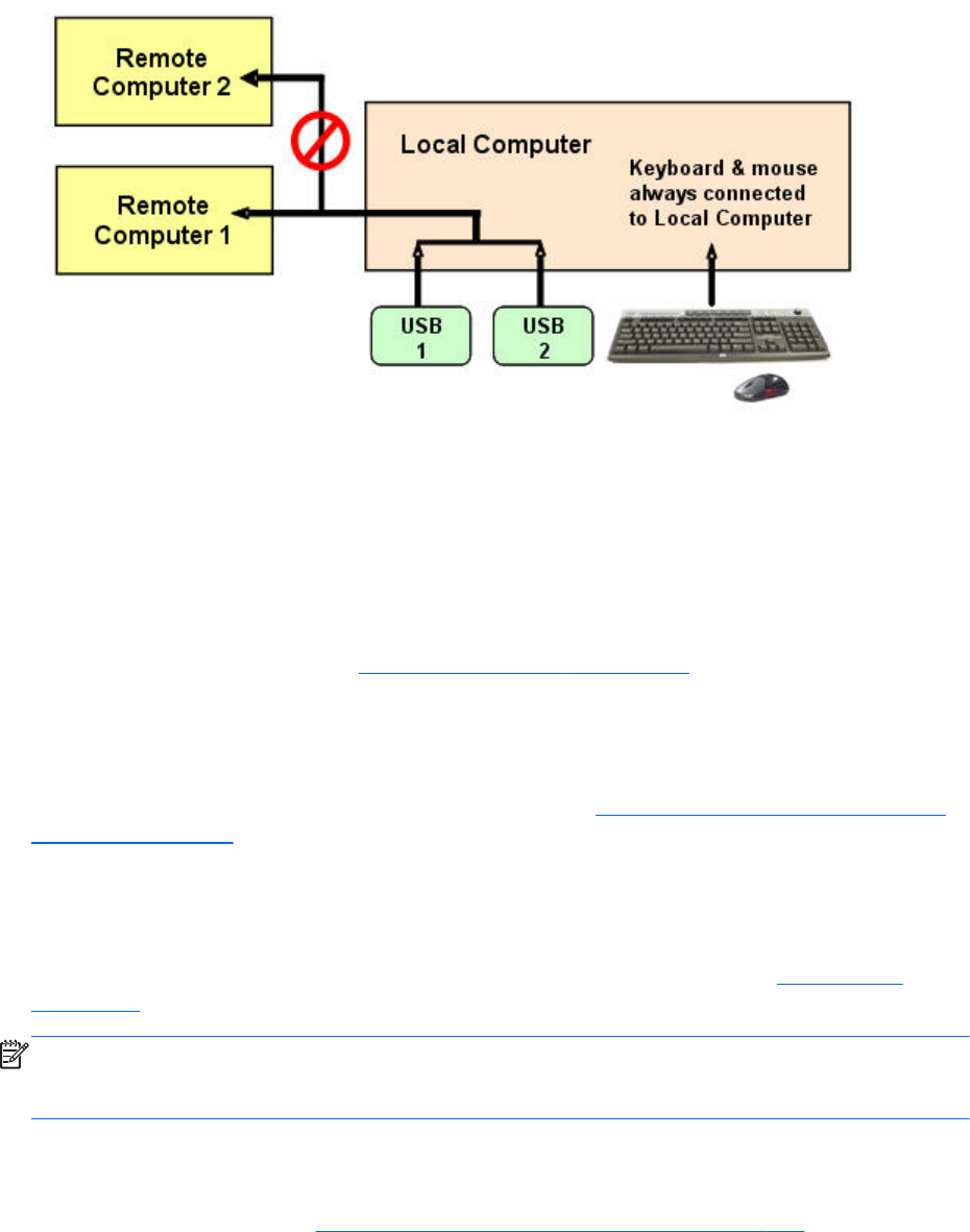
Figure 2-19 The local USB devices can be attached to only one Remote Computer at a time.
USB session switching
At RGS 5.1.3, the ability to dynamically move USB devices from one Remote Computer to another was
added. Prior to RGS 5.1.3, it was necessary to first disconnect all RGS connections (sessions) to the
Remote Computers, and then re-establish connections while specifying a new Remote Computer to
attach the USB devices to. With RGS 5.1.3, USB devices can be detached from one Remote Computer,
and made accessible by another Remote Computer without first needing to disconnect the RGS
connections. For details on this, see Remote USB operation on page 136 .
Isochronous USB support
At RGS 5.2.0, support was added for the USB isochronous data type, which is commonly used for
streaming data devices such as audio and video devices. See Support of sound recording devices on
Windows on page 42 for an overview of the two ways USB microphones can now be used with
RGS.
Install-time configuration of remote USB
This section provides an overview of install-time configuration of remote USB—see Installing RGS
on page 52 for more details.
NOTE: The Remote USB configuration cannot be changed after installation of the Sender and
Receiver—to select a different USB configuration option, the Sender or Receiver must be uninstalled and
reinstalled.
During installation of the RGS Receiver, you can select one of three Remote USB Configuration options,
local, remote or local then remote.
The "auto" option described in Local/Remote USB Device Management on page 140 alters this
behavior. It will re-enumerate any device marked as auto on connect and disconnect. For instance, you
have a USB key device that you have marked "auto". Until the Receiver is started it will be attached to
the local system. Once the Receiver is started and makes a connection to a Sender it will then be taken
Remote USB overview 31
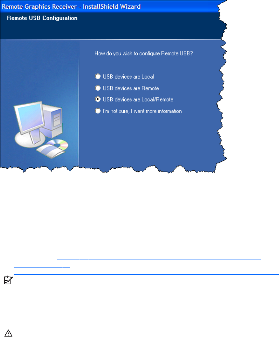
away from the local system and remoted to the Sender system. Upon disconnect it will be given back to
the local system.
Figure 2-20 Receiver installation dialog to specify the Remote USB Configuration
The three Remote USB Configuration options are:
1. USB devices are Local—All USB devices will remain local, and will be accessible only by the
Local Computer—none of the USB devices will be accessible by a Remote Computer.
2. USB devices are Remote—All USB devices can be accessed by the Remote Computer, and
none of the USB devices can be accessed by the Local Computer.
3. USB devices are Local/Remote—Whether USB devices are locally or remotely accessible
depends on when they are plugged into the Local Computer relative to establishment of an RGS
connection (see Figure 2-21 USB device accessibility for the setting “USB devices are Local/
Remote” on page 33).
NOTE: In addition to the general default settings for remote USB configurations, RGS 5.2.6 and
higher releases support auto-remote and auto-return of user-specified USB devices when using
Windows on both the Sender and Receiver platforms. RGS 5.4.0 introduced a new auto-remote
configuration syntax for the Windows Registry entries. Auto-remote allows specified USB devices
to be automatically attached to a remote Sender session at RGS connection and then returned to
the local client at RGS disconnect.
CAUTION: Enabling auto-remoting of specific USB devices requires modifications to the
Windows Registry. Registry modifications should only be made by experienced personnel.
Because an incorrect Registry setting can cause serious problems, you should always make a
backup of the Registry prior to making any changes.
32 Chapter 2 RGS overview
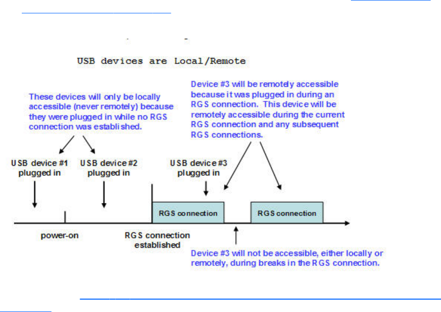
For information on how to modify the Registry to support auto-remoting. (see Local/Remote USB
Device Management on page 140
Figure 2-21 USB device accessibility for the setting “USB devices are Local/Remote”
As can be seen in Figure 2-21 USB device accessibility for the setting “USB devices are Local/Remote”
on page 33, USB device accessibility depends on when the USB device is plugged into the Local
Computer. If a USB device is inserted while no RGS connection is established, the device will be
locally-accessible only. If a USB device is inserted while an RGS connection is established, the device
will be remotely-accessible only.
Once a USB device is established as locally-accessible or remotely-accessible, its status can only be
changed by removing and inserting the device while in the alternate RGS connection state (either
connected or not connected). For example, to make a locally-accessible USB device remotely
accessible, the USB device needs to be removed and inserted after an RGS connection is established.
Unique smart card handling
New with RGS 5.1.3 is unique handling of USB smart card readers, including Common Access Card
(CAC) readers. Prior to RGS 5.1.3, smart card readers were handled in the same manner as other USB
devices, as described above. With RGS 5.1.3, smart card readers are now handled in a unique
manner, as follows:
●Unique smart card handling requires, on the Sender, that Easy Login be enabled.
Windows XP Professional – The chaining GINA module msgina.dll will be utilized.
Windows 7 – The HP ELO Credential Provider will be utilized.
●Unique smart card handling also requires that the Local and Remote Computers both be running
Windows.
●For USB configuration settings USB devices are Remote and USB devices are Local/
Remote, smart card readers will always be accessible by the Local Computer prior to
Remote USB overview 33
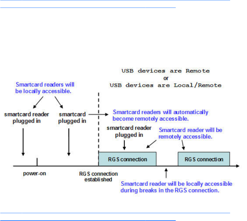
establishing a connection to a Remote Computer. This is to allow the smart card reader to be used
by the Local Computer prior to using the smart card to authenticate access to the Remote
Computer.
●Figure 2-22 Smart card reader accessibility pre- and post-RGS connection for settings “USB
devices are Remote” or “USB devices are Local/Remote” on page 34 shows the local and
remote accessibility of the smart card reader for USB configuration settings USB devices are
Remote and USB devices are Local/Remote. In both cases, smart card readers will be locally
accessible prior to establishing an RGS connection, and will be remotely accessible once an RGS
connection is established.
Figure 2-22 Smart card reader accessibility pre- and post-RGS connection for settings “USB
devices are Remote” or “USB devices are Local/Remote”
●Figure 2-22 Smart card reader accessibility pre- and post-RGS connection for settings “USB
devices are Remote” or “USB devices are Local/Remote” on page 34 indicates that the USB
devices are Remote and USB devices are Local/Remote settings are effectively ignored
for smart card readers. In particular, the USB devices are Remote setting is ignored as evidenced
by the smart card reader being locally accessible prior to establishment of an RGS connection.
Similarly, the USB devices are Local/Remote setting is ignored as evidenced by the locally-
accessible smart card reader automatically becoming remotely accessible once an RGS
connection is established.
●If a smart card reader is plugged in after an RGS connection is established, it will be available
remotely.
●If there is a break in the RGS connection, the smart card reader will become locally accessible.
If RDC is used to connect from the Local Computer to the Remote Computer, it is possible to get into a
situation where the smart card reader cannot be used to log into the Remote Computer (for details on
34 Chapter 2 RGS overview

the interoperability of RGS and RDC, see Interoperability of RGS and Microsoft Remote Desktop
Connection on page 48. This situation can arise as follows:
1. The user uses a smart card reader to log into the Remote Computer with RDC. Assume that this
login session is established from the user’s home.
2. Assume further that the user inadvertently leaves the RDC login session established, and departs
for work.
3. From work, the user attempts to log into the Remote Computer with RGS using an at-work smart
card reader in Easy Login mode (which is required for the smart card reader, as noted previously).
Because the home RDC login session is still active, RGS will require the user to authenticate the
connection (which is not normally required with Easy Login).
However, the user may not have a login name and password—the user may be totally relying on
smart card readers at home and at work to log into the Remote Computer. If the user is unable to
authenticate the connection with a user name and password, the USB smart card reader will not
be remotely mounted to the Remote Computer, and the user will not be able to log into the Remote
Computer.
4. To prevent this situation, the user should log out from the RDC session prior to leaving home.
5. To address this situation if it occurs, the user can do one of the following:
●Contact IT, and have an administrator log into the Remote Computer with RGS, which will
terminate the RDC session. After the administrator disconnects the RGS connection, the user
can establish an RGS connection using the smart card reader.
●Reboot the Remote Computer.
●Return home, and log out from the RDC session.
NOTE: Unlike RDC, an RGS user can leave a remote "user session" created from the home RGS
connection active and locked, and then log in from work with RGS. The home RGS connection must
be disconnected, but the remote user login can be left in an active and locked state as previously
stated. The smart card reader will operate correctly in both situations, and the work RGS login session
will replace the home login session. If the home RGS connection is left connected an Easy Login
connection from work will not succeed because of the existing connection and the user will be required
to perform steps similar to the steps in paragraph 5 above to be able to log in from work.
Remote USB overview 35

Computers supporting remote USB
Remote USB connections are supported by the computers and operating systems shown in the tables
below.
Table 2-4 Receiver remote USB support
Receiver Platforms Windows XPe/WES
2009/WES 7
Windows XP
Professional SP1,
SP2, SP3 32-bit,
x64
Windows 7
Professional and
Enterprise 32-bit
and 64-bit
Embedded Linux
Desktops
Personal Workstations X X
Mobile Workstations X X
Desktop PCs X X
Notebook PCs X X
Thin Clients
HP t5740 WES 2009
HP t5740e WES 7
HP t5745 HP ThinPro
HP t610 WES 7, WES 2009 HP ThinPro
HP gt7720 WES 2009
HP gt7725 HP ThinPro
HP 6360t WES 7, WES 2009
Table 2-5 Sender remote USB support
Sender Platforms Windows XP Professional SP1,
SP2, SP3 32-bit, x64
Windows 7 Professional and
Enterprise 32-bit and 64-bit
Blade Environments
HP Blade Workstations X X
VDI Servers X X
Desktops
Personal Workstations X X
Mobile Workstations X X
Desktop PCs X X
Notebook PCs X X
36 Chapter 2 RGS overview
Supported USB devices
The information in this section supersedes any previous supported USB device information.
Starting with the 5.2.0 release, RGS supports all USB transfer types (bulk, isochronous, interrupt and
control). This support means that a wide range of USB devices will work remotely with RGS.
RGS works very closely with the Windows USB driver stack. Any USB device that exclusively uses the
Windows USB driver stack for functionality should work with RGS. The less a USB device's driver
complies with the Windows USB driver stack, the less likely it will work with RGS.
Remote USB overview 37
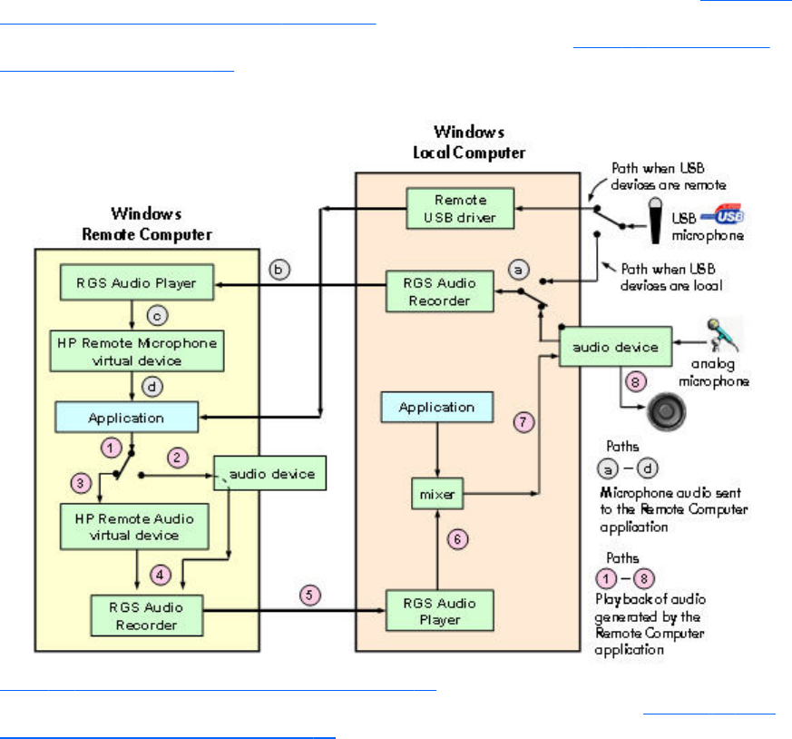
Remote audio
This section describes RGS support of remote audio on Windows and Linux. Rather than describe all
four combinations of Remote and Local Computers running Windows and Linux, the following sections
describe remote audio when both computers are running Windows, followed by a remote audio
description when both computers are running Linux.
Remote audio on Windows
RGS on Windows supports remote audio, allowing audio generated by the application on the Remote
Computer to be captured and transmitted to the Local Computer for playback. In addition, microphone
input on the Local Computer running Windows XP can be sent to the application running on the Remote
Computer also using Windows XP. Remote microphone is not supported on Windows 7. Figure 2-23
RGS audio subsystem on Windows on page 38 shows the RGS audio subsystem (green boxes) for
Windows, and the audio data paths—these data paths are described in Table 2-6 Windows RGS
audio data paths on page 39.
Figure 2-23 RGS audio subsystem on Windows
Table 2-6 Windows RGS audio data paths on page 39 describes each of the audio data paths. The
numbering and lettering in the table correspond to the numbering and lettering in Figure 2-23 RGS
audio subsystem on Windows on page 38.
38 Chapter 2 RGS overview

Table 2-6 Windows RGS audio data paths
Audio Playback from the Remote Computer to the
Local Computer
Sending of microphone audio from the Local
Computer to the Remote Computer
1. The application-generated audio output.
2. If an audio device is installed, the application-generated
audio is routed through it.
3. If there is no audio device (such as with a blade
workstation), the HP Remote Audio virtual device is
automatically installed, and the application-generated
audio is routed to it.
4. Audio from either the audio device or the HP Remote
Audio virtual device is sent to the RGS Audio Recorder.
5. The RGS Audio Recorder captures the audio, which is
sent by RGS to the Local Computer.
6. The RGS Audio Player on the Local Computer decodes
the received audio, and sends it to the audio mixer.
7. The output of the audio mixer is sent to the Local
Computer audio device.
8. The audio device drives an audio output device, such as
a speaker.
USB devices are local:
1. The user selects the microphone source, either a USB
microphone or an analog microphone. The RGS Audio
Recorder captures the selected microphone source.
2. The audio captured by the RGS Audio Recorder is sent
by RGS to the RGS Audio Player on the Remote
Computer.
3. The RGS Audio Player decodes the audio signal, and
sends it to the HP Remote Microphone virtual device.
4. The HP Remote Microphone virtual device appears to the
application as a local microphone, and sends the
microphone audio to the application.
USB devices are Remote: Beginning at RGS 5.2.0,
certain USB microphones can be mounted to the Remote
Computer using the remote USB driver for the supported
microphones. See the previous section for a description of
Remote USB operation.
In RGS 5.4.8, the device the audio is recorded from can be specified in the RGS Sender property
Rgsender.Audio.Linux.DeviceName.
Run the command:
cat /proc/asound/devices
From this, you will see a list of the audio devices and it will look something like this:
0: [ 0] : control
1: : sequencer
8: [ 0- 0]: raw midi
16: [ 0- 0]: digital audio playbac
17: [ 0- 1]: digital audio playback
24: [ 0- 0]: digital audio capture
32: [ 1] : control
33: : timer
48: [ 1- 0]: digital audio playback
56: [ 1- 0]: digital audio capture
Remote audio 39
There are two important things. The first is what’s between the “[ ]”. The first number is the “card”
(denoted “c” below) and the second number is the “device” (denoted “d” below). The second important
thing is the word “capture” in the description.
Rgsender.Audio.Linux.DeviceName=plughw:c,d
In the example above, depending upon which audio device you would like to capture the audio from,
you could specify the device with:
Rgsender.Audio.Linux.DeviceName=plughw:0,0
or
Rgsender.Audio.Linux.DeviceName=plughw:1,0
40 Chapter 2 RGS overview
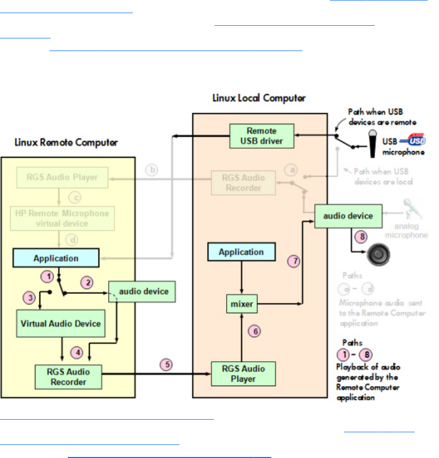
Remote audio on Linux
RGS on Linux also supports remote audio, allowing audio generated by the application on the Remote
Computer to be captured and transmitted to the Local Computer for playback. Figure 2-24 RGS audio
subsystem on Linux on page 41 shows the RGS audio subsystem (green boxes), and the audio data
paths for Linux—these data paths are described in Table 2-7 Linux RGS audio data paths
on page 42. To simplify comparison with Windows, all audio components shown on the Windows
diagram in Figure 2-23 RGS audio subsystem on Windows on page 38 are retained below, but
partially obscured if not supported on Linux.
Figure 2-24 RGS audio subsystem on Linux
Table 2-7 Linux RGS audio data paths on page 42 describes each of the audio data paths. The
numbering and lettering in the table correspond to the numbering and lettering in Figure 2-23 RGS
audio subsystem on Windows on page 38. For a list of audio devices supported on Linux Remote
Computers, see Linux remote audio device support on page 235 .
Remote audio 41

Table 2-7 Linux RGS audio data paths
Audio Playback from the Remote Computer to the
Local Computer
Sending of microphone audio from the Local
Computer to the Remote Computer
1. The application-generated audio output.
2. If an audio device is installed, the application-generated
audio is routed through it.
3. If the Virtual Audio Device is installed, the application
generated audio is routed through it.
4. Audio from either the audio device is sent to the RGS
Audio Recorder.
5. The RGS Audio Recorder captures the audio, which is
sent by RGS to the Local Computer.
6. The RGS Audio Player on the Local Computer decodes
the received audio, and sends it to the audio mixer.
7. The output of the audio mixer is sent to the Local
Computer audio device.
8. The audio device drives an audio output device, such as
a speaker.
USB devices are Local: RGS on Linux does not support
locally-mounted USB microphones.
USB devices are Remote: Beginning at RGS 5.2.0,
certain USB microphones can be mounted to the Remote
Computer using the remote USB driver. The Remote Computer
must be running Windows. Remote USB is not supported on
the Linux Sender. See the previous section for a description of
Remote USB operation.
Support of sound recording devices on Windows
NOTE: The Windows Sounds and Audio Devices Properties dialog allows the user to select
the “sound recording device”. For simplicity, “microphone” is used below instead of “sound recording
device”. Remote microphone is not supported on Windows 7.
Prior to RGS 5.2.0, a Receiver-attached USB microphone couldn’t be remotely connected to the Sender
in the same manner as other remote USB devices (see Remote USB overview on page 30 ). Audio from
a Receiver-attached USB microphone would need to be first processed by the Windows USB audio
driver on the Receiver. The audio would then be sent to the RGS Audio Recorder (see Remote audio on
Windows on page 38 ) for capture and transmission to the Sender.
In order for a USB microphone to be used in this manner, USB devices are Local must be selected in
the Remote USB Configuration dialog during installation. This ensures the USB microphone is a local
device, allowing its audio to be captured by the RGS Audio Recorder. This capability allows use of any
USB microphone supported by Windows.
At RGS 5.2.0, the Remote USB driver (on the Local Computer) has been enhanced to support the USB
isochronous data type, which is commonly used for streaming data such as that generated by audio
and video devices. This enables certain isochronous USB microphones to be accessed directly by the
Remote Computer in the same manner as other USB devices.
To remotely attach USB microphones to the Remote Computer, either of these Remote USB
Configuration settings can be selected:
●USB devices are Remote
●USB devices are Local/Remote
42 Chapter 2 RGS overview

If USB devices are Remote is selected, a USB microphone can be accessed anytime by the Remote
Computer. If USB devices are Local/Remote is selected, how the USB microphone can be
accessed by the Remote Computer depends on when the microphone is connected to the Local
Computer relative to establishment of the RGS connection. If the microphone is connected to the Local
Computer prior to establishment of the RGS connection, the microphone will be a local device only,
and will be accessible by the Remote Computer only via the Receiver RGS Audio Recorder. If the
microphone is connected to the Local Computer after RGS connection establishment, the microphone
will be a remote device only, and can be accessed directly by the Remote Computer. The figure in
Remote audio on Windows on page 38 shows these two cases.
HP recommends using the audio access method introduced at RGS 5.2.0, whereby the Remote
Computer can directly access the USB microphone, for the following reasons:
●The pre-RGS 5.2.0 audio access method continuously records and transmits audio independent of
whether the application on the Remote Computer is requesting audio input. This can consume
network bandwidth, especially when the level of background noise at the microphone is above the
audio threshold used to detect valid audio.
●The RGS 5.2.0 audio access method allows audio parameters to be set by audio controls on the
Remote Computer alone. The pre-RGS 5.2.0 audio access method requires setting audio
parameters on both the Remote Computer and Local Computer.
Computers and operating systems which support RGS audio
The table below shows the computers and operating systems that support RGS audio. For further details
on Remote Audio, see Remote audio operation on page 124.
Table 2-8 Receiver Remote Audio support
Receiver
Platforms
Windows XPe/
WES 2009/WES
7
Windows XP
Professional
SP1, SP2, SP3
32-bit, x64
Windows 7
Professional
and Enterprise
32-bit and 64-
bit
Embedded
Linux
RHEL V5.2 or
later; V6.2, 32-
bit, 64-bit
Desktops
Personal
Workstations
X X HP xw and z series
Mobile
Workstations
XX
Desktop PCs X X
Notebook PCs X X
Thin Clients
HP t5740 WES 2009
HP t5740e WES 7
HP t5745 HP ThinPro
HP t610 WES 7, WES
2009
HP ThinPro
Remote audio 43

Table 2-8 Receiver Remote Audio support (continued)
Receiver
Platforms
Windows XPe/
WES 2009/WES
7
Windows XP
Professional
SP1, SP2, SP3
32-bit, x64
Windows 7
Professional
and Enterprise
32-bit and 64-
bit
Embedded
Linux
RHEL V5.2 or
later; V6.2, 32-
bit, 64-bit
HP gt7720 WES 2009
HP gt7725 HP ThinPro
HP 6360t WES 7, WES
2009
Table 2-9 Sender remote Audio Support
Sender Platforms Windows XP
Professional SP1, SP2,
SP3 32-bit, x64
Windows 7 Professional
and Enterprise 32-bit
and 64-bit
RHEL V5.2 or later;
V6.2, 32-bit, 64-bit;
SLED 11, 32-bit, 64-bit
Blade Environments
HP Blade Workstations X X X
VDI Servers X X
Desktops
Personal Workstations X X HP only (customer configured)
Mobile Workstations X X
Desktop PCs X X
Notebook PCs X X
44 Chapter 2 RGS overview
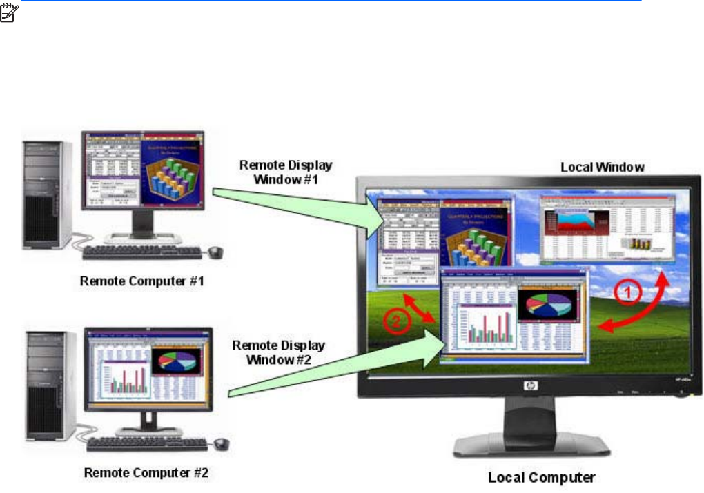
Remote Clipboard overview
Remote Clipboard was originally supported with RGS 5.1.3, enabling the user to cut or copy data
between a window on the Local Computer (the Local Window) and a Remote Display Window
(provided that both the Remote and Local Computers are running Windows, and the applications being
used support cut and paste, and copy and paste. Beginning with RGS 5.3.0, Remote Clipboard cut
and paste of ANSI text data is supported between Windows Receiver systems and Linux Sender
systems.
Beginning with RGS 5.4.8, the clipboard can be enabled to work on a limited permissions receiver
window for collaboration mode.
NOTE: For simplicity, the phrase “cut and paste” is used subsequently to refer to both cut and paste
as well as copy and paste.
At RGS 5.2, support was added for cut and paste between two Remote Display Windows (see the
graphic below).
Figure 2-25 Remote Clipboard operation
Cut and paste are supported in the following scenarios.
1. Between a Local Window and a Remote Display Window (in both directions)—The
Remote Computer may be running Windows or Linux. The Local Computer must be running
Windows.
2. Between two Remote Display Windows (in both directions)—In this case, the Local
Computer can be running either Windows or Linux; the Remote Computers may be running
Windows or Linux.
Remote Clipboard overview 45
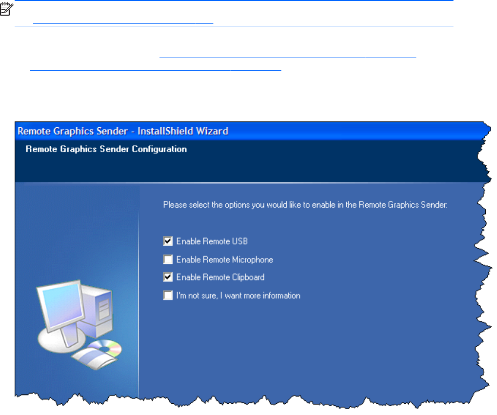
NOTE: Not all data formats can be transferred using cut and paste between Windows applications.
See Remote Clipboard operation on page 159 for detailed information on the supported formats.
In order for Remote Clipboard to be usable, it must be enabled during both the Sender and Receiver
installations on Windows (see the Manual installation of the Receiver on Windows on page 53” and
the Manual installation of the Sender on Windows on page 59) for further information on Remote
Clipboard installation.
Figure 2-26 Enabling Remote Clipboard during Sender and Receiver installation on Windows
systems.
46 Chapter 2 RGS overview
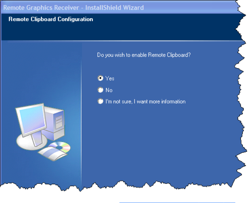

Interoperability of RGS and Microsoft Remote
Desktop Connection
This section discusses interoperability considerations for RGS and Remote Desktop Connection (RDC).
Because RGS and RDC both provide connection to a remote desktop, their interoperation is important
to understand.
If a local user is connected to a Remote Computer using RDC, and then attempts to establish an RGS
connection, the RGS connection only works if the local user credentials match for both connections. This
implies that the same user wants access to transition from RDC to an RGS connection. If the credentials
match, the current RDC session disconnects, and the RGS Receiver takes control of the Remote
Computer Windows desktop session. The current user does not log off, and work continues with the
new connection.
The reverse works as well. If a user is connected with RGS, and then connects with RDC (using the
same credentials as the RGS connection), the RDC session displaces the RGS connection. In this case,
the RGS Sender will disconnect all Receivers (including all RGS collaborators). The Windows desktop
session remains active during the switch.
If an RDC user disconnects from a Remote Computer using the RDC disconnect button, the session
remains logged in, and all applications continue to run. The session, however, locks its screen. An RGS
connection works only if the credentials match the currently logged-in user.
If a user logs out of their session while using RDC, the RGS Sender returns the system to its initial
logged out state. Any authorized user can connect and log into this system using RGS.
An RDC connection made to a Sender already occupied with a RGS connection by a non-matching
user prompts the new user to logout the current RGS user. Only administrators can log out other users.
Non-administrators are refused with a warning message about permissions. If RDC logs out the current
RGS user, then the Sender disconnects all of its receivers (including all RGS collaborators).
Under reverse circumstances for the above, RGS connections will not log out an existing RDC user,
regardless of authority. RGS will report an authorization failure message concerning a different user
owning the desktop
When RGS displaces an existing RDC session on Windows 7, the desktop may enter into a temporary
logged in and unlocked state due to these operations. The user should exercise caution in situations
where even a temporarily unlocked desktop is a security concern.
Cause Solution
Windows 7 performs session operations that are outside the
control of RGS.
This issue can be avoided by logging out of the RDC session
before establishing an RGS connection.
Remote Computer power saving states
In order for a Local Computer to establish connection to a Remote Computer, the Remote Computer
cannot be in a power saving state, such as Windows hibernate or standby. Furthermore, the Remote
Computer cannot utilize wake-on-LAN in an attempt to power-up in order to respond to a connection
48 Chapter 2 RGS overview
request from the Local Computer—the Remote Computer must be powered-up, and able to respond to
an RGS connection request at all times.
Supported keyboard locales
The following keyboard localizations are supported when connected to a Linux Sender:
1. French
2. German
3. Japanese
4. Norwegian
5. Swedish
6. United Kingdom
7. U.S. English
The following keyboard localizations are supported when connected to a Windows Sender:
1. Belgian French
2. Canadian French
3. Chinese (Simplified) – US Keyboard
4. Chinese (Traditional) – US Keyboard
5. Czech
6. Czech (QWERTY)
7. Danish
8. Dutch
9. Finnish
10. French
11. German
12. Italian
13. Japanese
14. Korean
15. Latin American
16. Norwegian
17. Portuguese
Supported keyboard locales 49
18. Portuguese (Brazilian ABNT)
19. Russian
20. Spanish
21. Swedish
22. Swiss French
23. Swiss German
24. Turkish Q
25. United Kingdom
26. United Kingdom Extended
27. United States-International
28. US
RGS security features
Because of the distributed nature of an RGS connection, providing connection security is critically
important. RGS implements many features to provide connection security, including:
●Authentication: When a local user attempts to connect to a Remote Computer, the user
credentials are validated using the native authentication method on the Remote Computer. If the
credentials are not authenticated, the connection is closed. On Windows, authentication uses
NTLM or Kerberos. On Linux, authentication uses the Pluggable Authentication Module (PAM).
●Authorization: Multiple connections to the same Remote Computer are only allowed if the user
logged into the desktop of the Remote Computer (primary user) allows the connection. When
another user attempts to connect to the Remote Computer, an authorization dialog is displayed on
the desktop of the Remote Computer that asks whether the new user should be allowed to connect.
●Automatic desktop locking: The desktop of the Sender system locks when the primary user
disconnects. This prevents collaboration users from being able to interact with a remote session
after the primary user has disconnected. This feature is supported on Windows. On Linux, this
feature is supported on the Gnome, KDE, and CDE desktop environments.
●Automatic disconnect: On Linux, all Receivers will disconnect when the primary user
disconnects. This prevents collaboration users from interaction with a remote session after the
primary user disconnects.
●Automatic disconnect of collaboration users on Login: All collaboration users are
disconnected when a login event occurs. Only the primary user remains connected when the
desktop of the remote computer is logged in.
●Automatic disconnect on log off: All Receivers are disconnected when the primary user logs
off of the remote desktop. This can be disabled by setting the IsDisconnectOnLogoutEnabled
Sender property to "0". See the Sender properties for more information.
50 Chapter 2 RGS overview

●Connection status: A desktop icon in the application tray animates when other users are
connected.
●Collaboration notification: See Collaboration notification dialog on page 116.
●Connections are not allowed when an iLO remote console is enabled: If the iLO
remote console is enabled on a HP Blade Workstation, connections to the blade using RGS are
denied.
●Disconnect Everyone: All Receivers can be easily disconnected using the Sender GUI. This is
useful when hosting a collaboration session, such as in a classroom environment, and the session
ends. The Sender GUI is an icon in the system tray. Simply right-click the GUI and select
Disconnect >Everyone.
●Remote Keyboard/Mouse: The Sender GUI can enable or disable mouse and keyboard input
for all collaboration users.
●Single user connection: A user, identified by a username, is only allowed one connection to a
RGS Sender. If the same username connects more than once to a Sender, the previous connection
drops and the new connection continues on. If several users attempt to share a username, only one
connection is active at a time.
●SSL encryption: SSL securely encrypts all data transmitted between a Receiver and Sender pair.
RGS security features 51

3 Installing RGS
This chapter describes the following aspects of installing RGS:
●Installing the RGS Receiver on Windows
●Installing the RGS Sender on Windows
●Installing the RGS Receiver on Linux
●Installing the RGS Sender on Linux
NOTE: RGS licensing applies to the RGS Sender only. The RGS Receiver is a free download and can
be used on any number of computers. Licensing of the RGS Sender on Windows and Linux is described
in the HP Remote Graphics Software Licensing Guide, available at http://www.hp.com/support/
rgs_manuals. Note that Sender licensing is checked when an RGS connection is established; therefore,
the licensing mechanism has no affect on downloading the RGS product, and installing the RGS
Sender.
However, as described in RGS licensing on page 14 , installing the RGS Sender without a valid license
will result in an error dialog being displayed in the Remote Display Window. Therefore, before
downloading a new RGS version, and installing a new RGS Sender, ensure that your RGS license
entitles you to use the new Sender version. Again, refer to the HP Remote Graphics Software Licensing
Guide at http://www.hp.com/support/rgs_manuals for detailed information.
NOTE: The RGS Sender is configured to start when the Sender computer boots (or, in the case of
Linux, also when the X server starts). The RGS Receiver can be started from a command line. However,
because the Receiver can also be started from the menu, both methods of starting the Receiver (on a
command line and using the menu) are described together, in Using RGS in Normal Mode
on page 101 .
52 Chapter 3 Installing RGS

Installing RGS on Windows
This section describes installation of the RGS Receiver and Sender on Windows. See Supported
computers and operating systems on page 10 for a list of the Windows operating systems that support
the RGS Receiver and Sender.
Installing the Receiver on Windows
This section describes manual and automatic installation of the RGS Receiver on Windows.
Manual installation of the Receiver on Windows
To install the Receiver on Windows, log into an account with administrator privileges, and perform the
following steps:
1. Go to the directory where you downloaded RGS, and change to the directory
WIN
32\
RECEIVER
.
2. Double-click Setup.exe to start the Receiver installation, and follow the instructions on the screen.
Installing RGS on Windows 53
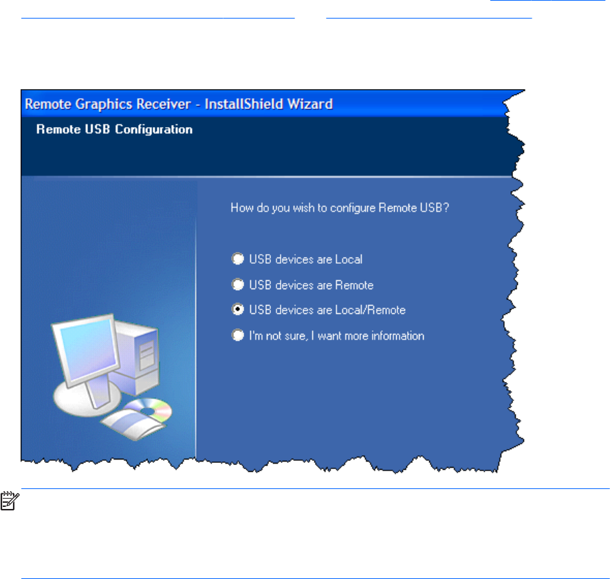
3. During the installation, the Remote USB Configuration dialog is displayed (see Figure 3-1 Receiver
Remote USB configuration dialog on page 54 and Remote USB overview on page 30). To see
additional information, select I’m not sure, I want more information, and click Next.
Select the USB configuration option that meets your needs, and click Next.
Figure 3-1 Receiver Remote USB configuration dialog
NOTE: For many USB devices, the Windows operating system provides default USB drivers.
While these default drivers may, in fact, work with your USB devices, it is recommended that you
install the manufacturer supplied USB drivers to optimize functionality and performance of your
USB devices. The manufacturer supplied driver should be installed on the computer, Local or
Remote, where the USB devices will be logically (not physically) attached.
54 Chapter 3 Installing RGS
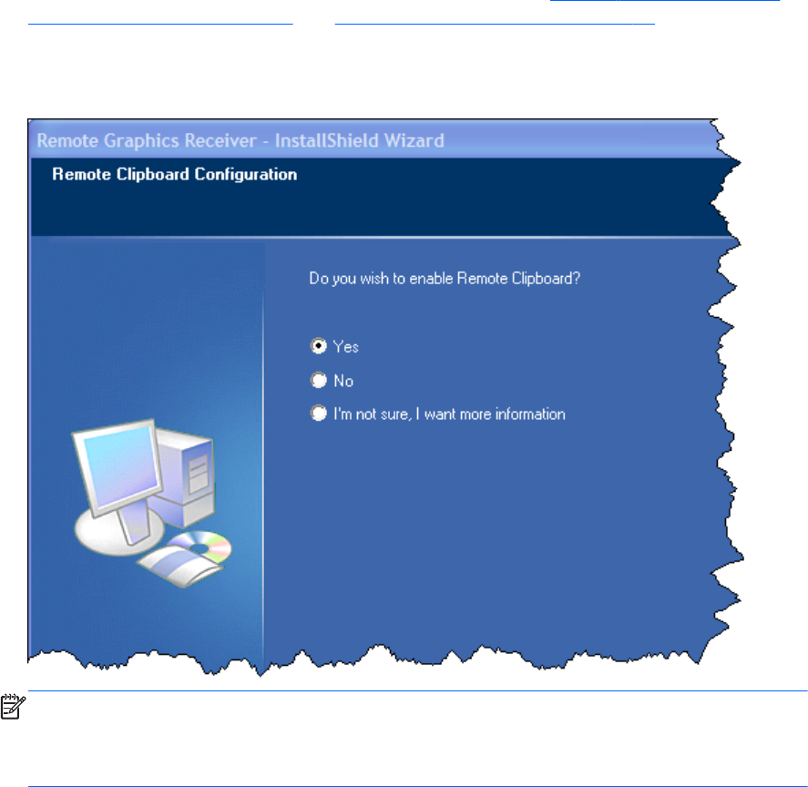
4. The Remote Clipboard Configuration dialog is displayed next (seeFigure 3-2 Remote Clipboard
Configuration dialog on page 55 and Remote Clipboard overview on page 45). To see
additional information, select I’m not sure, I want more information, and click Next.
Select the desired Remote Clipboard Configuration option, and click Next.
Figure 3-2 Remote Clipboard Configuration dialog
NOTE: Selecting “Yes” will cause the hprclipboard.dll library to be installed with the RGS
Receiver. If you select “No”, this DLL won’t be installed and you won’t be able to use Remote
Clipboard. To enable Remote Clipboard later, you would need to reinstall the RGS Receiver, and
select “Yes” in the above dialog.
5. The final installation step will normally prompt you to restart your computer.
Automatic installation of the RGS Receiver on Windows
The RGS Receiver can be installed or removed in automatic mode. Automatic mode allows the Receiver
to be installed or removed without any user interaction. Automatic mode will also restart the computer,
if required, after the installation process completes.
Should an illegal combination of command line options be specified, or if an error occurs during the
install process, the install will abort and the error will be logged to the Receiver installation log file.
Setup will exit without making any changes if automatic installation of the same version currently
installed is attempted.
Installing RGS on Windows 55

Usage
Setup.exe /autoinstall /agreetolicense [/folder=<folder>]
[/usb=local | /usb=remote | /usb=localRemote]
[/clipboard]
[/noreboot]
Setup.exe /autoremove [/noreboot]
Setup.exe /viewlicense
Setup.exe /help
Command line options
/autoinstall
This option performs one of the following:
●Installs the Receiver if it is not currently installed.
●Updates the Receiver if a prior version of the Receiver is currently installed.
●Exits without changes if the version being installed is the same as the version that is currently
installed.
The Receiver will not be reinstalled if the version of the Receiver being installed is older than the version
of the Receiver currently installed.
/agreetolicense
Use of this option indicates that the user agrees to the license for use of this software. This option is
required when doing an install.
/autoremove
Remove the Receiver.
/folder=<folder>
Specifies the destination folder, default is C:\Program Files\Hewlett-Packard\Remote Graphics Receiver.
/usb=local
Install USB in Local Mode.
56 Chapter 3 Installing RGS

/usb=remote
Install USB in Remote Mode. The system will automatically restart after the install completes.
/usb=localRemote
Install USB in Local/Remote Mode. The system will automatically restart after the install completes. This is
the default if none of /usb=local, /usb=remote, and /usb=localRemote are specified.
/clipboard
Enable remote clipboard.
/noreboot
Do not reboot the system when the setup requires a reboot to complete.
/viewlicense
Displays the EULA (End User License Agreement) for use of this software.
/help
Display usage text.
Receiver installation log file
Installation of the Receiver creates an installation log file. This log file can be viewed by the user to
obtain details about what operations were performed, and view any errors that occurred during the
installation process. When Setup.exe for the RGS Receiver is run, the following log file is created:
%TEMP%\rgreceiverInstaller
The log file is especially useful for automatic installs because installer errors are not displayed on the
screen, and are only viewable using the log file. If the log file already exists when the installer is run,
the installer will remove the current contents of the log file before writing to it. This prevents the log file
from growing without bounds.
Installing RGS on Windows 57
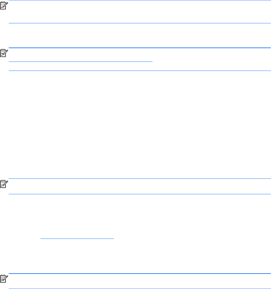
Uninstalling the RGS Receiver on Windows
To uninstall the RGS Receiver, use the Windows Add or Remove Programs feature from the Control
Panel. Select Remote Graphics Receiver, and click Remove. A dialog box will open with choice of
REMOVE or Exit without changes. Choose REMOVE to uninstall the RGS Receiver. On certain
client computers simply re-run the setup.exe program that you used to originally install the Receiver in
place of using the Windows Add or Remove Programs feature.
NOTE: After the Receiver is uninstalled, you may be prompted to restart your computer. This restart is
very important—if it is not performed, installation of a later version of the RGS Receiver may not
succeed.
Installing the Sender on Windows
NOTE: The Sender can only be installed on the computers and operating systems shown in
Supported computers and operating systems on page 10. Installing the Sender on a non-supported
computer will prevent an RGS connection from being established.
This section covers the following topics:
●Prerequisites for Sender installation on Windows 7
●Manual installation of the Sender on Windows
●The Sender diagnostics tool, rgdiag.exe
●Starting and stopping the Sender
●Sender command line options on Windows
●The Sender GUI
●Automatic installation of the RGS Sender on Windows
NOTE: Starting with RGS 5.1.3, installation of the Sender on Windows may be performed remotely
using Remote Desktop Connection.
Prerequisites for Sender installation on Windows 7
Prior to installing the Sender on Windows 7, if an NVIDIA driver is not currently installed and is
required, the NVIDIA graphics driver must be installed first. The latest NVIDIA driver for your product is
available at http://www.hp.com/support. Select Download drivers and software. Enter the
product to search for. Select the OS. Scroll down to Driver — Graphics — NVIDIA. Download the
driver. Windows 7 systems require driver version 191.56 and later.
Install the NVIDIA graphics driver following the instructions in the download package.
NOTE: Installing the NVIDIA graphics driver after the Sender has been installed may prevent the use
of Windows Aero on Windows 7.
58 Chapter 3 Installing RGS
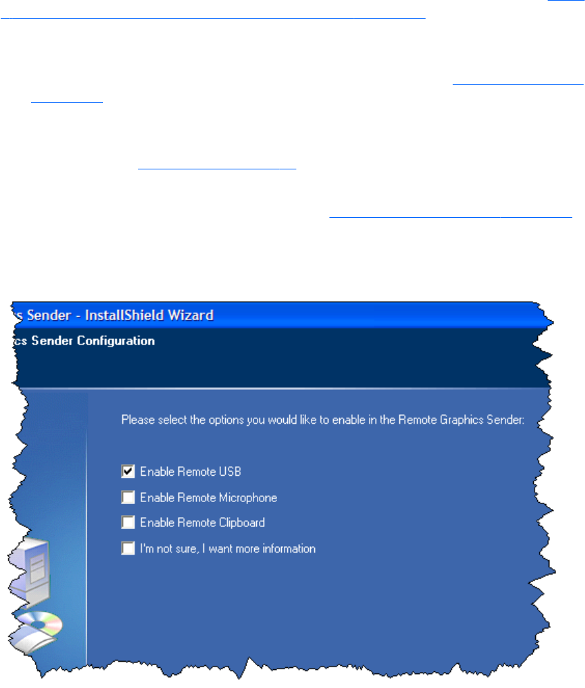
Manual installation of the Sender on Windows
To install the Sender on Windows, log into an account with administrator privileges, and perform the
following steps:
1. Go to the directory where you downloaded RGS, and change to the directory win32\sender.
2. Double-click Setup.exe to start the Sender installation, and follow the instructions on the screen.
3. During the installation, the Remote Graphics Sender Configuration dialog is displayed (see Figure
3-3 Dialog to enable or disable Remote USB in the Sender on page 59). Check the boxes
appropriate to your requirements, as follows:
●Enable Remote USB—Check this box if USB devices attached to the Local Computer need
to be accessible by the Remote Computer. For further information, see Remote USB overview
on page 30.
●Enable Remote Microphone—Check this box to enable remote microphone. Remote
microphone is not supported on Windows 7 therefore; this option is not available on
Windows 7. (see Remote audio on page 38)
●Enable Remote Clipboard—Check this box if your Local Users will need Remote
Clipboard capability. For further information, see Remote Clipboard overview on page 45
●I’m not sure, I want more information—For further information, check this box, and
click Next.
Figure 3-3 Dialog to enable or disable Remote USB in the Sender
Installing RGS on Windows 59
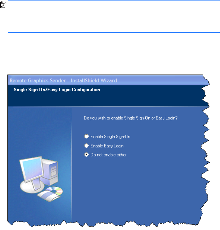
NOTE: For many USB devices, the Windows operating system provides default USB drivers.
While these default drivers may, in fact, work with your USB devices, it is recommended that you
install the manufacturer supplied USB drivers to optimize functionality and performance of your
USB devices. The manufacturer supplied USB driver should be installed on any computer, Local or
Remote, where the USB devices will be logically (not necessarily physically) attached.
4. If you are installing the Sender on HP blade workstations or HP personal workstations running
Windows XP Professional or Windows 7, you will be presented with a dialog to enable either
Single Sign-On or Easy Login. If you’re not sure, you will be able to configure them later using the
rgadmin.exe tool.
Figure 3-4 Dialog to enable Single Sign-On or Easy Login
60 Chapter 3 Installing RGS
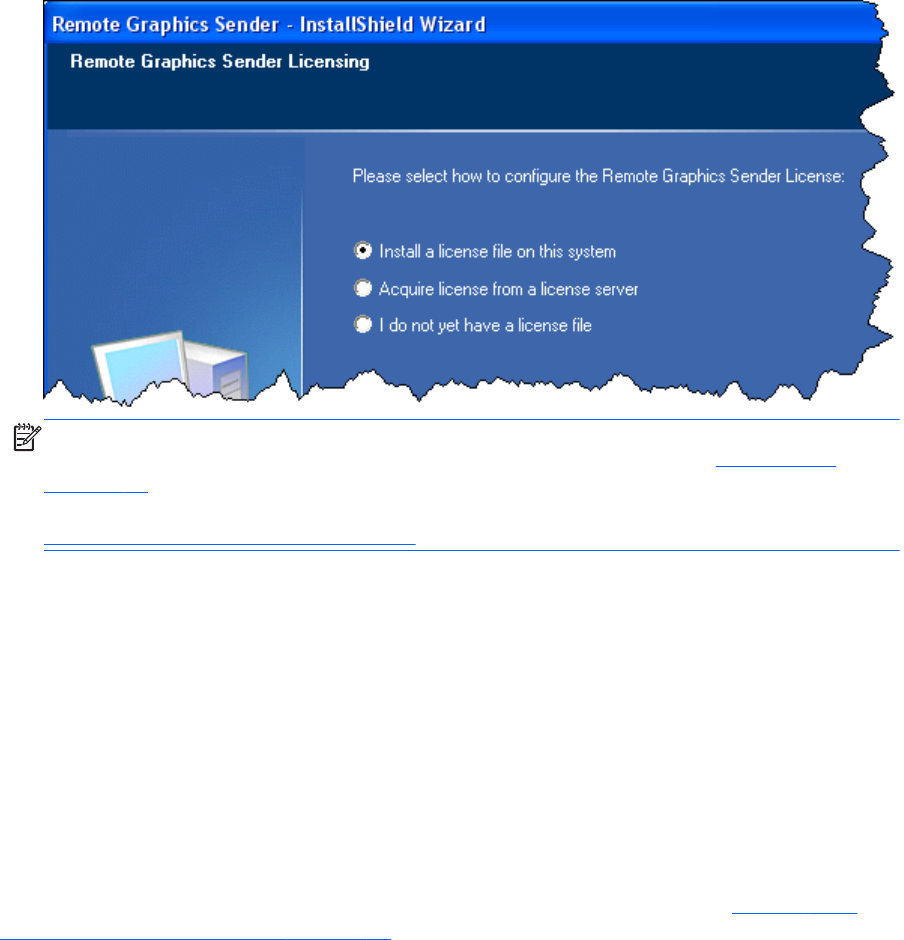
5. Next, the Sender installer will prompt you for the Sender license. If you have a Sender license file,
click the appropriate radio button, click Next, and provide the requested information. If you don’t
yet have a license file, click I do not yet have a license file, and click Next. You can install
your license file later.
Figure 3-5 Configuration of the RGS Sender license
NOTE: Absent a license file, the RGS Sender will still function correctly, and you’ll be able to
establish a connection from the RGS Receiver. However, the dialog shown in RGS licensing
on page 14 will be displayed in the Remote Display Window. Installation of the license file is
described in detail in the HP Remote Graphics Software Licensing Guide, available at
http://www.hp.com/support/rgs_manuals
6. You will be prompted to restart your computer after the Sender installation is complete. Select yes
when asked to restart the system.
Starting and stopping the Sender on Windows
The Sender is automatically started each time Windows starts.
The Sender installer adds a new Windows Service. This is necessary to enable some features, such as
the ability to send CTRL-ALT-DEL key sequences, and also view locked screens. Additionally, installing
the Sender service executable as a service allows Windows to automatically start the Sender service
process when the computer is started.
You can control Windows Services by accessing the "Services" panel. The "Services" panel can be
accessed from the Windows Control Panel by selecting Administrative Tools. Figure 3-6 The
Remote Graphics Sender service on page 62 shows the Administrative Tool for Services. The Remote
Graphics Sender is highlighted. The status of the service is "Started", and the service is configured to
start up automatically. By right-clicking on the Remote Graphics Sender service, the service can be
Installing RGS on Windows 61
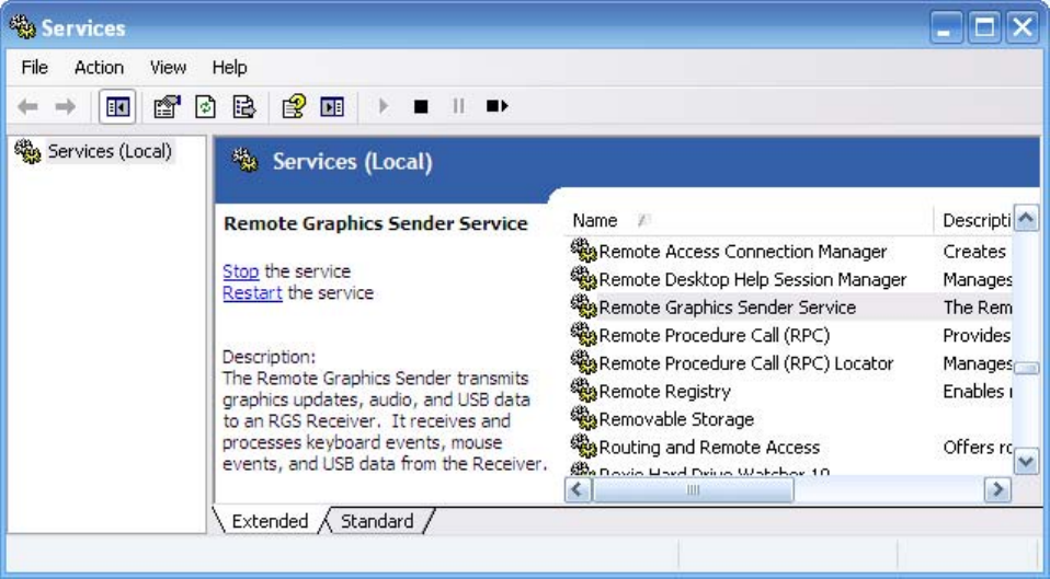
stopped, started, or resumed. Additionally, the properties of the service can be controlled such as the
start-up type and the recovery mode.
Figure 3-6 The Remote Graphics Sender service
Sender command line options on Windows
The Windows Sender is comprised of two processes, one of which runs as a Windows Service. When
the Remote Computer boots, the installed services are typically started. The service process,
rgsendersvc.exe will then start the RGS Sender process rgsender.exe. When the RGS Sender is
installed, an entry is added in the Windows Registry for the Remote Graphics Sender service.
rgsender.exe supports the following options passed to it via registry parameters to rgsendersvc.exe (see
the registry editing instructions below):
[-nocollab]
[-timeout value]
[-authtimeout value]
[-l logSetupFile]
[-v | -ver | -version]
[-h | -help | -?]
[-belownormal | -normal | -abovenormal | -high]
[-Rgsender.propertyname=value]
The functionality of each option is as follows:
62 Chapter 3 Installing RGS

-nocollab—Disables collaboration. When specified, only the primary user can connect to the Sender.
-timeout value—The timeout in milliseconds used to detect and disconnect an inactive connection. This
option sets the property Rgsender.Network.Timeout.Error. See Adjusting Network timeout settings
on page 148 for more details.
-authtimeout value—The timeout in milliseconds used to detect and notify the user of a network
disruption. This option sets the property Rgsender.Network.Timeout.Dialog. See Adjusting Network
timeout settings on page 148 for more details.
-l logSetupFile—Specifies the "logSetupFile" file used to describe various logging parameters for Sender
error and informational output. This file is used to determine where the output goes (to a file or to
standard error) as well as the type of output logged (INFO or DEBUG). At installation, the Sender
default is with "-l logSetup" turned on, where the logSetup file in the installation directory is set for
output to a file named rg.log at INFO debug level.
[-v | -ver | -version] —Prints the Senders version information and is useful from a command window.
[-h | -help | -?] —Prints a listing of the various command line options, those that are listed on this page
and is useful from a command window.
-belownormal —Sets the process priority of the Sender to below normal.
-normal —Sets the process priority of the Sender to normal. This is the default priority.
-abovenormal —Sets the process priority of the Sender to above normal.
-high —Sets the process priority of the Sender to high.
-Rgsender.propertyname=value—Can be used to specify one or more RGS Sender properties. See RGS
properties on page 174 for general information on RGS properties. For information specifically on
RGS Sender properties, see RGS Sender properties on page 199
regedit can be used to modify the parameters that are used for starting the Sender by the Sender
service as follows:
1. Start regedit —This can be done by opening a Windows command prompt and executing the
command “regedit” or using the "run" command line from the Start menu.
2. Using regedit, navigate to the key:
HKEY_LOCAL_MACHINE\SYSTEM\CurrentControlSet\Services\rgsender
3. 3. Add the desired process priority command-line option for starting the Remote Graphics Sender
service. For example, to increase the process priority to high add the “-high” option to the key
“ImagePath” as follows: "C:\Program Files\Hewlett-Packard\Remote Graphics Sender
\rgsendersvc.exe":
-l logSetup -high
4. Restart the Sender service and RGS Sender with the new option. This can be done using the
Windows Service Control Manager (see Starting and stopping the Sender on Windows
on page 61) or by re-starting the computer.
Installing RGS on Windows 63

The Sender GUI on Windows
The Sender displays the HP Remote Graphics Software icon in the application tray. The icon animates
when Receivers are connected to the Sender. Right-click the icon to display the Sender GUI (see Figure
3-7 Sender GUI on page 64).
Figure 3-7 Sender GUI
The following options are provided by the Sender GUI:
●Collaborator Input > Enable or Disable—If Disable is selected, all local users are in view-
only mode—only the primary user can control the Remote Computer desktop using a keyboard
and mouse. If Enable is selected, all local users (and the primary user) can interact with the
Remote Computer desktop.
●Disconnect > Collaboration Users or Everyone—Disconnects Receiver sessions for either
collaboration users or all users.
●About—Displays the RGS program information.
Setting the Windows Sender process priority
This section discusses adjusting the process priority of the Windows Sender. The default process priority
of the Windows Sender is normal. In some cases, increasing the process priority of the Sender will
improve interactivity— for example, when the Windows scheduling algorithms does not give the RGS
Sender sufficient CPU time to maintain smooth interactivity. Networking performance can also
contribute to reduced interactivity.
The Windows Sender on some laptops has exhibited inconsistent performance. Increasing the Sender
priority to high usually improves interactivity in this case. This provides the Sender more frequent
access to the CPU, and improves the update frequency to the Receiver.
Process priority for the Sender is command line accessible for the Windows Sender. Four command-line
options are available:
●-belownormal
●-normal
●-abovenormal
●-high
Priorities low and realtime cannot be selected for the Windows Sender.
64 Chapter 3 Installing RGS

There are two ways to set the process priority of the Windows Sender:
●Use regedit to modify the rgsender service start up parameters in the Windows Registry. (see the
regedit instructions in the Sender command line options on Windows on page 62 section)
●Use HP Performance Advisor (HP PA) to configure Windows Sender priority (available only on HP
Workstations)
CAUTION: Adjusting the process priority of the Sender to a level higher than –normal can cause
other normally privileged processes to receive fewer CPU cycles than normal. Therefore, caution should
be observed in adjusting the priority of the Sender.
Setting the Sender process priority using HP PA
The HP Performance Advisor (HP PA) can be used adjust the priority of the Sender without having to
use regedit. HP PA is available for HP Workstations only from this location: http://www.hp.com/go/
performanceadvisor
See the HP PA help and documentation for further information.
Installing and enabling Single Sign-on
CAUTION: Installing RGS Single Sign-on is for experienced users and IT administrators only. Please
read all directions completely before proceeding, and exercise caution when installing.
Windows XP Professional – The RGS shared library, hprgina.dll, enables Single Sign-on. The file
hprgina.dll is a GINA (Graphical Identification and Authentication) module that is loaded by the
Windows XP Professional WinLogon.exe process. There are three ways to install hprgina.dll, and
therefore enable RGS Single Sign-on for Windows XP Professional.
Windows 7 – Single Sign-on for Windows 7 uses the RGS SSO Credential Provider. The Credential
Provider can only be installed during RGS installation or by running the rgadmin tool.
Enabling Single Sign-on during installation
Single Sign-on can be enabled during Figure 3-8 The dialog presented during Sender installation to
enable Single Sign-on or Easy Login on page 66 installation—enabling Single Sign-on installs the
hprgina.dll module on Windows XP Professional or the RGS SSO Credential Provider on Windows 7.
This is the preferred method to enable Single Sign-on. The default during installation is to not enable
Single Sign-on. The administrator must answer two questions to enable Single Sign-on (see Figure 3-8
The dialog presented during Sender installation to enable Single Sign-on or Easy Login on page 66).
Installing RGS on Windows 65
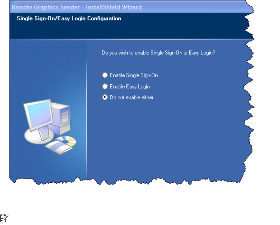
If Single Sign-on is enabled and the computer is running Windows XP Professional, the computer must
be restarted before Single Sign-on is operational.
Figure 3-8 The dialog presented during Sender installation to enable Single Sign-on or Easy Login
Using the rgadmin tool to enable Single Sign-on
NOTE: The rgadmin tool is only installed and supported on Windows XP and Windows 7.
The rgadmin tool can be used to enable Single Sign-on—check the Enable Single Sign-on radio button
and click Apply. Enabling Single Sign-on installs the hprgina.dll module on Windows XP Professional
or the RGS SSO Credential Provider on Windows 7. Using the rgadmin tool to enable Single Sign-on is
preferred over the manual method, described next for Windows XP Professional.
66 Chapter 3 Installing RGS
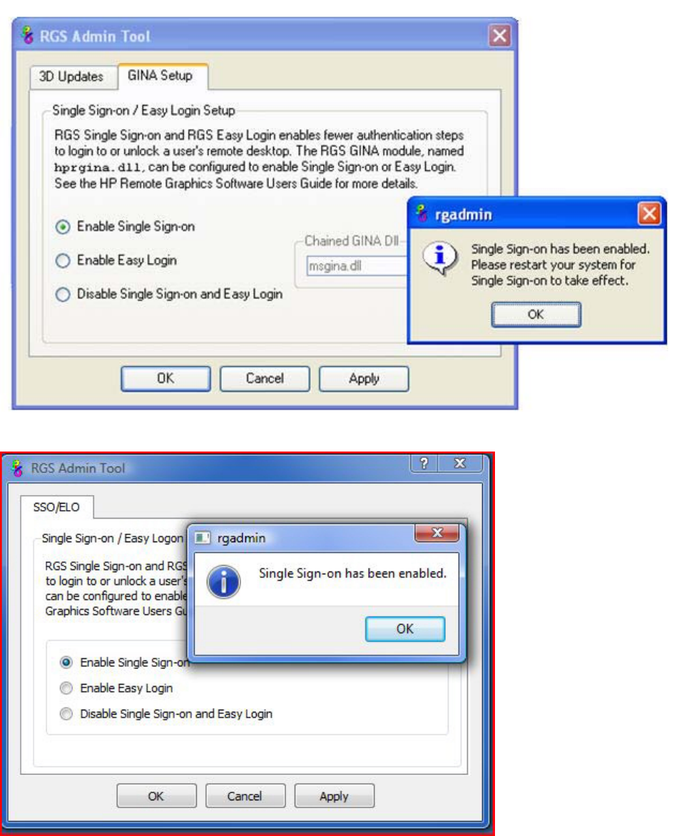
Figure 3-9 Using the rgadmin tool to enable Single Sign-on (Windows XP Professional)
Figure 3-10 Using the rgadmin tool to enable Single Sign-on (Windows 7)
Installing RGS on Windows 67
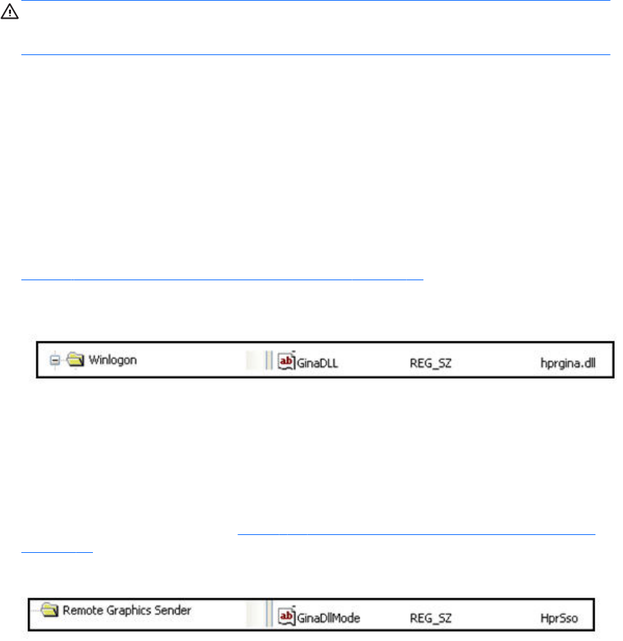
Manually enabling Single Sign-on (Windows XP Professional only)
Although the manual method is not the preferred method to enable Single Sign-on, it is provided so that
administrators will know exactly what parts of the operating system are being modified. To manually
enable Single Sign-on, perform the following steps:
1. Install the Sender on the HP workstation. If the RGS Sender is not installed or installs with errors,
DO NOT perform the remaining steps. Doing so will put the computer in a state that requires a
complete re-installation of the operating system.
2. After the RGS Sender is installed, confirm that hprgina.dll exists in the C:\WINDOWS\system32
directory. The Sender installer copies hprgina.dll directly into the system32 directory.
CAUTION: If the hprgina.dll does not exist in C:\WINDOWS\system32, do not perform the
remaining steps. Doing so will put the system in a state that requires a complete re-installation of
the operating system.
3. Add the GinaDLL registry key if it does not already exist. If the GinaDLL key does not exist, the
Microsoft default GINA DLL (msgina.dll) is loaded by WinLogon. Adding the GinaDLL registry key,
and setting its value to hprgina.dll informs WinLogon to load hprgina.dll instead of the default
msgina.dll.
Adding the GinaDLL registry key is done using regedit, the Windows Registry Editor. Create the
key as type REG_SZ (a string type). The full path of the key is:
HKEY_LOCAL_MACHINE\Software\Microsoft\Windows NT\CurrentVersion
\Winlogon\GinaDll
4. Set the value of the GinaDLL key to the text "hprgina.dll". Confirm the spelling before closing.
Figure 3-11 Addition of the GinaDLL key to the registry on page 68 shows the registry key
contents.
Figure 3-11 Addition of the GinaDLL key to the registry
5. Add the GinaDllMode registry key if does not already exist. This can be done through the use of
regedit as well. Create the key as type RGS_SZ (a string type). The full path of the key is:
HKEY_LOCAL_MACHINE\Software\Hewlett-Packard\Remote Graphics Sender
\GinaDllMode
6. To actually enable Single Sign-on, set the value of the GinaDllMode key to the text "HprSso".
Confirm the spelling before closing. Figure 3-12 Addition of the GinaDllMode key to the registry
on page 68 shows the registry key contents.
Figure 3-12 Addition of the GinaDllMode key to the registry
7. Restart the computer. The hprgina.dll module will be loaded by WinLogon when started.
68 Chapter 3 Installing RGS
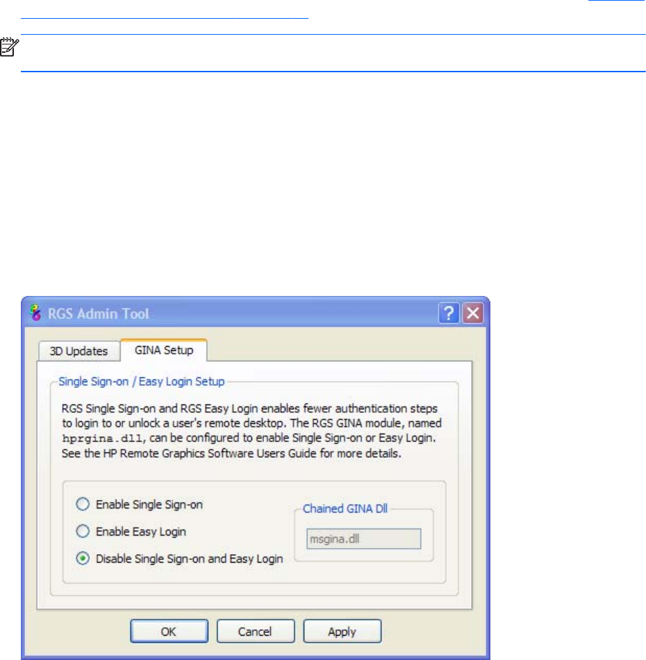
Summary—If the GinaDLL key does not currently exist in the registry, the Microsoft default GINA DLL
(msgina.dll) is loaded by WinLogon. Adding the GinaDLL registry key, and setting its value to
hprgina.dll, informs WinLogon to load hprgina.dll instead of the default msgina.dll.
Setting the local security policy (Windows XP Professional only)
The local security policy "Interactive logon: Do not require CTRL-ALT-DEL" must be disabled to support
Single Sign-on. This can be set in the Windows "Local Security Settings" under "Security Options." The
RGS Diagnostics Tool programmatically detects if this local security policy is set correctly. See Using the
RGS Diagnostics Tool on Windows on page 80 for information on this tool.
NOTE: Creating the GinaDLL registry key disables the Windows "Fast User Switching" and
"Welcome Screen" features.
Disabling Single Sign-on
The methods to disable Single Sign-on are described below.
Using the rgadmin tool to disable Single Sign-on
Using the rgadmin tool to disable Single Sign-on is preferred over the manual method for Windows XP
Professional, described next. The rgadmin tool must be used to disable Single Sign-on for Windows 7.
Select Disable Single Sign-on and Easy Login, and then click Apply.
Figure 3-13 Using rgadmin to disable Single Sign-on (Windows XP Professional)
Installing RGS on Windows 69

Figure 3-14 Using rgadmin to disable Single Sign-on (Windows 7)
Manually disabling Single Sign-on (Windows XP Professional only)
To disable Single Sign-on without using the rgadmin tool, delete or rename the value of the GinaDLL
registry key. If there is no other custom GINA module on the computer, simply removing the GinaDLL
key definition from the registry entry below disables Single Sign-on.
HKEY_LOCAL_MACHINE\Software\Microsoft\Windows NT\CurrentVersion\Winlogon
\GinaDll
CAUTION: If the value of the GinaDLL key contains the name of a custom GINA DLL, and the file
does not exist in C:\WINDOWS\system32, the computer will not start correctly after the next reboot.
The computer will then require a complete re-installation of the operating system.
GinaDLL key is removed using regedit, the Windows Registry Editor. Be sure to actually remove the key
by selecting the GinaDLL key in regedit, and select the Delete entry in the Edit menu. Once the key is
deleted, it will no longer show up as a key in the WinLogon subkey. When the system reboots, the
default GINA module, msgina.dll, will be loaded by the WinLogon.exe process.
If there is a custom GINA DLL module on the system, and if it replaces the default msgina.dll, change
the value of the GinaDLL value from hprgina.dll to the name of the custom GINA module. To change
the value of the GinaDLL key, select the GinaDLL key in regedit, and then select the Modify entry in the
Edit menu. A dialog box appears allowing the value of the key to be changed. Type the name of the
custom GINA module in the "Value data:" area. Confirm that the custom GINA module entered
actually exists in C:\WINDOWS\system32. When the computer restarts, the custom GINA module will
be loaded by the WinLogon.exe process.
70 Chapter 3 Installing RGS

Installing and Enabling Easy Login
CAUTION: Installing RGS Easy Login is for experienced users and IT administrators only. Please read
all directions completely before proceeding, and exercise caution when installing.
Easy Login is only supported on HP blade workstations running the RGS Sender. The RGS shared
library, hprgina.dll, enables Easy Login for Windows XP Professional. The file hprgina.dll is a GINA
(Graphical Identification and Authentication) module that is loaded by the Windows XP Professional
WinLogon.exe process. There are three ways to install hprgina.dll for Windows XP Professional, and
therefore enable RGS Easy Login on the Sender. The RGS ELO Credential Providers enable Easy Login
for Windows 7. Easy Login for Windows 7 must be enabled during RGS installation or by running the
rgadmin tool. In RGS 5.4.8 and later, Easy Login can be enabled on Linux by adding the following
properties to the rgsenderconfig file:
●Rgsender.IsAnonymousConnectionForceEnabled=1
●Rgsender.IsClassicEasyLogonEnabled=1
Enabling Easy Login during installation
Easy Login can be enabled during RGS Sender installation—enabling Easy Login installs the hprgina.dll
module for Windows XP Professional or the RGS ELO Credential Providers for Windows 7. This is the
preferred method to enable Easy Login. The default during installation is to not enable Easy Login. The
user must answer two questions to enable Easy Login, as shown in Figure 3-8 The dialog presented
during Sender installation to enable Single Sign-on or Easy Login on page 66. If the computer is
running Windows XP Professional, the computer must be restarted before Easy Login is operational.
Using the rgadmin tool to enable Easy Login
The rgadmin tool can be used to enable Easy Login—check the Enable Easy Login radio button and
click Apply. Enabling Easy Login installs the hprgina.dll module for Windows XP Professional or the
Installing RGS on Windows 71
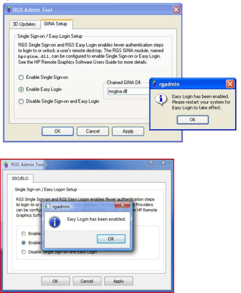
RGS ELO Credential Providers for Windows 7. Using the rgadmin tool to enable Easy Login is
preferred over the manual method, described next for Windows XP Professional.
Figure 3-15 Using the rgadmin tool to enable Easy Login (Windows XP Professional)
Figure 3-16 Using the rgadmin tool to enable Easy Login (Windows 7)
72 Chapter 3 Installing RGS
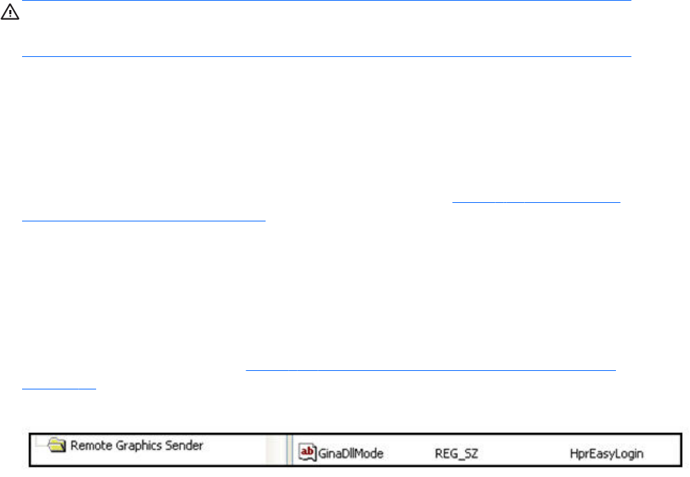
Manually enabling Easy Login (Windows XP Professional only)
Although the manual method is not the preferred method to enable Easy Login, it is provided so that
administrators will know exactly what parts of the operating system are being modified. To manually
enable WinLogon to load the hprgina.dll module, perform the following steps:
1. Install the Sender on the HP workstation. If the RGS Sender is not installed or installs with errors,
do not perform the remaining steps. Doing so will put the computer in a state that requires a
complete re-installation of the operating system.
2. After the RGS Sender is installed, confirm that hprgina.dll exists in the C:\WINDOWS\system32
directory. The Sender installer copies hprgina.dll directly into the system32 directory.
CAUTION: If the hprgina.dll does not exist in C:\WINDOWS\system32, do not perform the
remaining steps. Doing so will put the system in a state that requires a complete re-installation of
the operating system.
3. Add the GinaDLL registry key if it does not already exist. This can be done through the use of
regedit, the Windows Registry Editor. Create the key as type REG_SZ (a string type). The full path
of the key is:
HKEY_LOCAL_MACHINE\Software\Microsoft\Windows NT\CurrentVersion
\Winlogon\GinaDLL
4. Set the value of the GinaDLL key to the text "hprgina.dll" as shown in Figure 3-11 Addition of the
GinaDLL key to the registry on page 68. Confirm the spelling before closing.
5. Add the GinaDllMode registry key if does not already exist. This can be done through the use of
regedit as well. Create the key as type RGS_SZ (a string type). The full path of the key is:
HKEY_LOCAL_MACHINE\Software\Hewlett-Packard\Remote Graphics Sender
\GinaDllMode
6. To actually enable Easy Login, set the value of the GinaDllMode key to the text "HprEasyLogin".
Confirm the spelling before closing. Figure 3-17 Addition of the GinaDllMode key to the registry
on page 73 shows the registry key contents:
Figure 3-17 Addition of the GinaDllMode key to the registry
7. Restart the computer. The hprgina.dll module will be loaded by WinLogon when started.
Summary—If the GinaDLL key does not currently exist in the registry, the Microsoft default GINA DLL
(msgina.dll) is loaded by WinLogon. Adding the GinaDLL registry key, and setting its value to
hprgina.dll, informs WinLogon to load the hprgina.dll instead of the default msgina.dll.
The hprgina module is a chaining GINA DLL. When the RGS hprgina.dll is loaded by WinLogon, the
hprgina module loads the msgina.dll shared library. The hprgina module chains (forwards) all GINA
requests to the msgina.dll module.
Installing RGS on Windows 73
Chaining custom GINA modules for Easy Login (Windows XP Professional
only)
If it is determined in step 3 above that the GinaDLL registry key does exist, and the value of the key is
not msgina.dll, then a custom GINA module is currently loaded and being used by WinLogon. Custom
GINA modules provide custom authentication dialogs or even custom user authentication methods. If it
is determined that functionality of both the RGS Easy Login and a custom GINA module is required, the
hprgina.dll needs further configuration. The hprgina.dll module needs to be set up to load the custom
GINA module rather than the default msgina.dll as described above. There are three ways to enable
the hprgina.dll module to load a custom GINA module:
Install time specification of the custom GINA module
A custom GINA module can be chained by the hprgina.dll at install time. This is the preferred method.
The installer will bring up a GUI that allows the Easy Login GINA module (hprgina.dll) to be enabled,
as well as provides a text box to enter the name of the custom GINA module. The name of the custom
module is all that is needed, provided it is installed in the C:\WINDOWS\system32 directory. If the
custom module is installed elsewhere, the full file path needs to be entered.
Using the rgadmin tool to specify a custom GINA module
The rgadmin tool can be used to chain a custom GINA module. When Enable Easy Login is
selected, the associated text entry box Chained GINA Dll is not grayed out. Enter the name of the
custom GINA module in the text box, and click Apply. Using the rgadmin tool to specify a custom
GINA module is preferred over the manual method, described next.
Manually enabling hprgina.dll to load a custom GINA module
To manually enable the hprgina.dll module to load a custom GINA module, create a new registry key,
ChainedGinaDLL, with the value of the key containing the name of the chained custom GINA module.
Perform steps 1–6 shown above (the restart will be done below) plus the following three steps to chain
custom modules:
1. Create the ChainedGinaDLL registry key. Create the key as type REG_SZ (a string type). The full
path of the key is:
HKEY_LOCAL_MACHINE\Software\Hewlett-Packard\Remote Graphics Sender
\ChainedGinaDLL
2. Set the value of the new ChainedGinaDLL key to the name of the custom GINA module. For
example, if the name of the custom GINA module is foogina.dll, then the value of the key should
be foogina.dll. The value should match the string originally discovered in the registry key GinaDLL.
Confirm the spelling before closing.
3. Restart the computer.
When the RGS hprgina.dll is loaded by WinLogon, hprgina.dll will load the chained GINA
module foogina.dll. The hprgina module then chains all GINA requests to the foogina.dll module.
If the custom foogina.dll is also a chaining GINA module, foogina.dll, in turn, chains itself to the
msgina.dll module. Three GINA DLLs will be loaded as part of the WinLogon.exe process: (1)
hprgina.dll, (2) foogina.dll, and (3) msgina.dll.
74 Chapter 3 Installing RGS
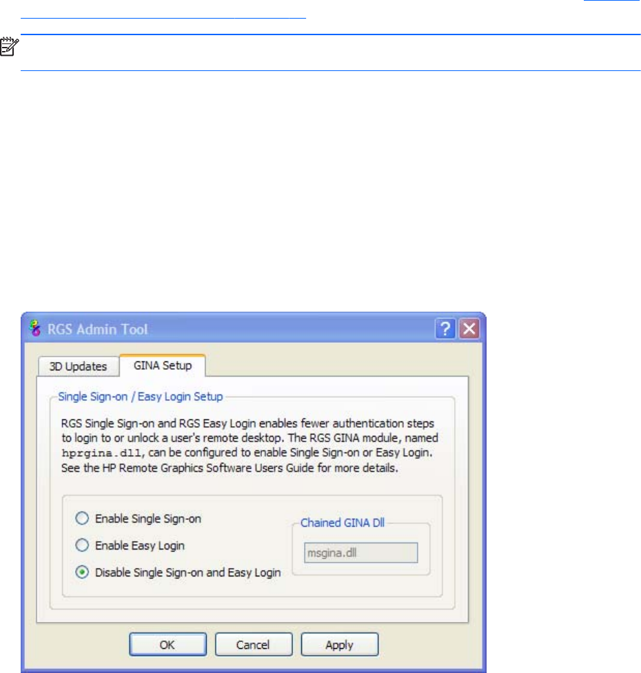
Setting the Local Security Policy (Windows XP Professional)
The local security policy "Interactive logon: Do not require CTRL-ALT-DEL" must be disabled to support
Easy Login. This can be set in the Windows "Local Security Settings" under "Security Options." The
RGS Diagnostics Tool programmatically detects if this local security policy is set correctly. See Using the
RGS Diagnostics Tool on Windows on page 80 for more information.
NOTE: Creating the GinaDLL registry key disables the Windows "Fast User Switching" and
"Welcome Screen" features.
Disabling Easy Login
The methods to disable Easy Login are described below.
Using the rgadmin tool to disable Easy Login
The rgadmin tool can be used to disable Easy Login. Using the rgadmin tool to disable Easy Login is
preferred over the manual method, described next for Windows XP Professional. The rgadmin tool must
be used to disable Easy Login for Windows 7.
Select Disable Single Sign-on and Easy Login, and then click Apply.
Figure 3-18 Using rgadmin to disable Easy Login (Windows XP Professional)
Installing RGS on Windows 75
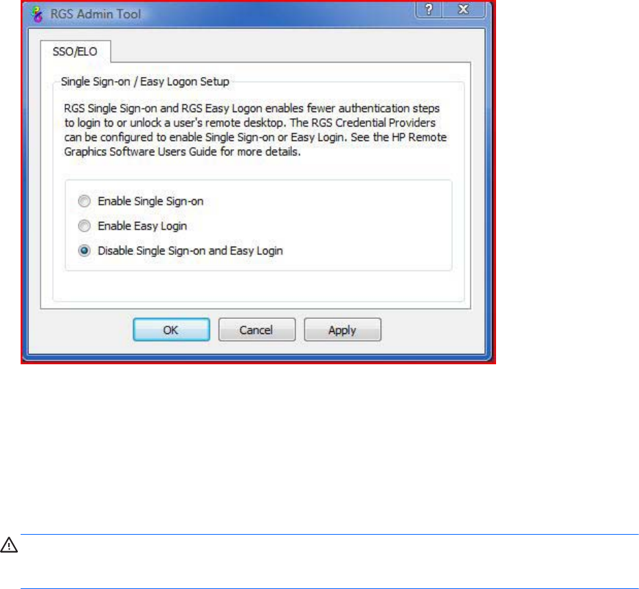
Figure 3-19 Using rgadmin to disable Easy Login (Windows 7)
Manually disabling Easy Login (Windows XP Professional only)
To disable Easy Login without using the rgadmin tool, delete or rename the value of the GinaDLL
registry key. If there is no other custom GINA module on the system, simply removing the GinaDLL key
definition from the registry entry below disables Easy Login.
HKEY_LOCAL_MACHINE\Software\Microsoft\Windows NT\CurrentVersion\Winlogon
\GinaDll
CAUTION: If the value of the GinaDLL key contains the name of a custom GINA DLL, and the file
does not exist in C:\WINDOWS\system32, the system will not start correctly upon the next reboot. The
system will then require a complete re-installation of the operating system.
The GinaDLL key is removed using regedit, the Windows Registry Editor. Be sure to actually remove the
key by selecting the GinaDLL key in regedit, and select the Delete entry in the Edit menu. Once the key
is deleted, it no longer shows up as a key in the WinLogon subkey. When the system reboots, the
default GINA module, msgina.dll, will be loaded by the WinLogon.exe process.
If there is a custom GINA DLL module on the system and it replaces the default msgina.dll, change the
value of the GinaDLL value from hprgina.dll to the name of the custom GINA module. To change the
value of the GinaDLL key, select the GinaDLL key in regedit, and then select the Modify entry in the Edit
menu. A dialog box appears allowing the value of the key to be changed. Type the name of the custom
GINA module in the "Value data:" area. Confirm that the custom GINA module entered actually exists
on the system in C:\WINDOWS\system32. When the system reboots the custom GINA module is
loaded by the WinLogon.exe process.
76 Chapter 3 Installing RGS

Manually disabling Easy Login (Linux only)
In RGS 5.4.8 and later, Easy Login can be disabled on Linux by adding the following properties to the
rgsenderconfig file:
Rgsender.IsAnonymousConnectionForceEnabled=0
Rgsender.IsClassicEasyLogonEnabled=0
Automatic installation of the RGS Sender on Windows
The RGS Sender can be installed or removed in automatic mode. Automatic mode allows the Sender to
be installed or removed without any user interaction. Automatic mode will also restart the computer, if
required, after the installation process completes.
Should an illegal combination of command line options be specified, or if an error occurs during the
install process, the install will abort and the error will be logged to the Sender installation log file. Setup
will exit without making any changes if automatic installation of the same version currently installed is
attempted.
Usage
Setup.exe /autoinstall /agreetolicense [/folder=<folder>]
[/usb]
[/remotemic]
[/clipboard]
[/sso | [/el [/gina=<filename>]]]
[/rgslicenseserver=<port@host> | /rgslicensefile=<filename>]
[/noreboot]
Setup.exe /autoremove [/noreboot]
Setup.exe /viewlicense
Setup.exe /help
Installing RGS on Windows 77

Command line options
/autoinstall
This option performs one of the following:
●Installs the Sender if it is not currently installed.
●Updates the Sender if a prior version of the Sender is currently installed.
●Exits without changes if the version being installed is the same as the version that is currently
installed.
The Sender will not be reinstalled if the version of the Sender being installed is older than the
version of the Sender currently installed.
/agreetolicense
Use of this option indicates that the user agrees to the license for use of this software. This option is
required when doing an install.
/autoremove
Remove the Sender.
/folder=<folder>
Specifies the destination folder, default is C:\Program Files\Hewlett-Packard\Remote Graphics
Sender.
/usb
Enable remote USB.
/remotemic
Enable remote microphone.
/clipboard
Enable remote clipboard.
78 Chapter 3 Installing RGS

/sso
Enable Single Sign-on, only one of /sso and /el can be used.
/el
Enable Easy Login, only one of /sso and /el can be used.
/gina=<filename>
Chaining GINA module to use, default is "msgina.dll", can only be specified if /el is used.
/rgslicenseserver=<port@host>
The license to run the RGS Sender is acquired from a license server listening on the
specified port and host. The port/host must be in the form of port@host. The port and
the trailing “@” are optional, in which case the default port is used for the given
host. Only one of /rgslicenseserver= or /rgslicensefile= may be specified.
/rgslicensefile=<filename>
The license to run the RGS Sender is acquired from the specified file. The filename may be
omitted by specifying the option as “/rgslicensefile=”, in which case the Sender will be
installed without a license, and the license file can be manually copied to the install folder at a
later time. Only one of /rgslicenseserver= or /rgslicensefile= may be specified. If neither /
rgslicenseserver= or /rgslicensefile= are specified, the install will proceed as if this option was
specified without a filename.
/noreboot
Do not reboot the system when the setup requires a reboot to complete.
/viewlicense
Displays the EULA (End User License Agreement) for use of this software.
/help
Display usage text.
Installing RGS on Windows 79

Sender installation log file on Windows
As with installation of the Receiver, installation of the Sender also creates an installation log file. This
log file can be viewed by the user to obtain details about what operations were performed, and view
any errors that occurred during the installation process. When Setup.exe for the RGS Sender is run, the
following log file is created:
%TEMP%\rgsenderInstaller
The log file is especially useful for automatic installs because installer errors are not displayed on the
screen, and are only viewable using the log file. If the log file already exists when the installer is run,
the installer will remove the current contents of the log file before writing to it. This prevents the log file
from growing without bounds.
Uninstalling the RGS Sender on Windows
To uninstall the RGS Sender, use the Windows Add or Remove Programs feature from the Control
Panel. Select Remote Graphics Sender, and click Remove A dialog box will open with choices for:
Remove – Retain User Settings, Remove – Delete User Settings, Exit without changes.
Retain User Settings will leave the user specific Sender settings in the registry while Delete User Settings
removes the user specific Sender settings from the registry.
NOTE: After the Sender is uninstalled, you will be prompted to restart your computer. This restart is
very important—if it is not performed, installation of a later version of the RGS Sender may not
succeed.
Using the RGS Diagnostics Tool on Windows
During the installation of the Windows Sender, the RGS Diagnostics Tool (rgdiag.exe) is installed. The
tool can be used to detect potential issues (such as Windows firewall settings, Guest Account security
policies, RDC interoperability, and Easy Login settings) that might prevent a remote connection. The
80 Chapter 3 Installing RGS
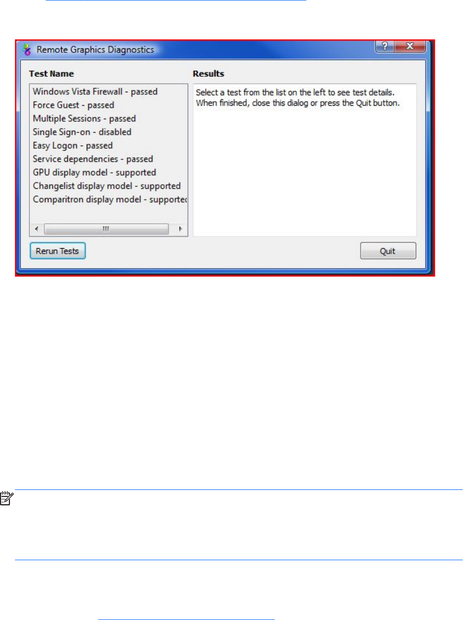
dialog Figure 3-20 Output of the RGS Diagnostics Tool on page 81 shows the output generated by
the tool.
Figure 3-20 Output of the RGS Diagnostics Tool
The Test Name left panel shows the list of tests that have been run. Selecting a test with the mouse
will display additional information in the Results right panel. The Rerun Tests button on the bottom
left reruns all tests. The example window shows that all tests have passed. If a test failed, click the test
title to display its details in the Results panel. This information can be used to determine what this test
looked for, why it failed, whether this failure would prevent connections, and suggestions on how to fix
the problem.
The RGS Diagnostics Tool can be run any time after RGS Sender installation. To run the Diagnostics
Tool, use Windows Explorer to display the RGS Sender installation folder, and locate the rgdiag.exe
program with the RGS icon. On a 32-bit Windows system, this tool is normally located at:
C:\Program Files\Hewlett-Packard\Remote Graphics Sender\rgdiag.exe
Using the rgadmin tool
The rgadmin tool is described for use on Windows XP Professional and Windows 7.
NOTE: The rgadmin tool is only installed and supported on Windows XP and Windows 7.
This section describes use of the Sender rgadmin.exe tool. For a normal Sender installation, this tool
can be found at:
C:\Program Files\Hewlett-Packard\Remote Graphics Sender\rgadmin.exe
rgadmin tool on Windows XP Professional
When run on Windows XP Professional, the rgadmin.exe program displays two tabs. The 3D
Updates tab (see Figure 3-21 3D Updates tab on page 82) can be used to enable automatic 3D
Installing RGS on Windows 81
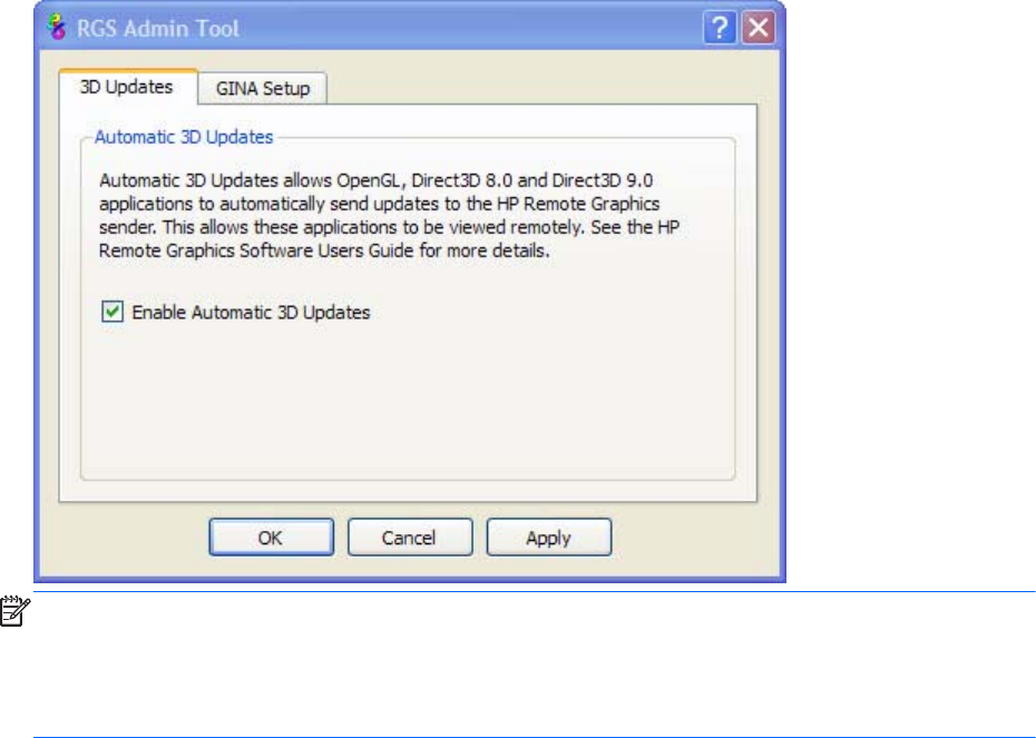
updates from the application to the Sender. These updates inform the Sender what screen rectangles
have been changed by the 3D application.
Figure 3-21 3D Updates tab
NOTE: RGS versions prior to RGS 4.0 required the manual placement of the RGS OpenGL32.dll
library into the application directory for each application. For RGS 4.0 and later, this library may
cause applications to fail on startup. Because automatic updates of OpenGL applications are now
supported, the OpenGL32.dll library is no longer required, and should be removed from any
application directories where it resides.
When rgadmin is started, it reports the current status of Single Sign-on and Easy Login. To change the
status, check the desired radio button. After clicking Apply, you’ll be requested to restart your
computer if the computer is running Windows XP Professional—this is required in order for the new
setting to take affect.
82 Chapter 3 Installing RGS
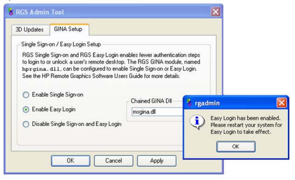
Figure 3-22 Dialog to enable or disable Single Sign-on and Easy Login (Windows XP Professional)
rgadmin tool on Windows 7
Beginning with RGS 5.4.8, rgadmin is supported on Windows 7 to enable and disable both Single
Sign-on and Easy Login
Installing RGS on Windows 83
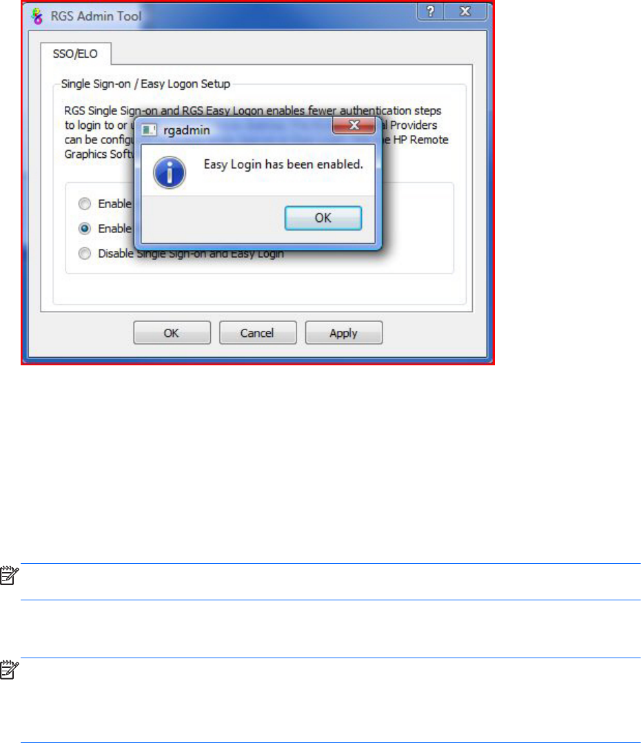
When rgadmin is started, it reports the current status of Single Sign-on and Easy Login. To change the
status, check the desired radio button. After clicking Apply, Single Sign-on or Easy Login are
immediately available on Windows 7.
Figure 3-23 Dialog to enable or disable Single Sign-on and Easy Login (Windows 7)
Installing RGS on Linux
This section describes how to:
●Install and uninstall the RGS Receiver on Linux
●Audio requirements for the Linux Receiver
●Install and uninstall the RGS Sender on Linux.
NOTE: The RGS Sender uses TCP/IP port 42966. The Linux installer adds an iptables entry to open
this port.
Installing the Receiver on Linux
NOTE: Beginning with RGS 5.1.3, the Linux RGS Receiver is available in both 32-bit and 64-bit
versions. The Xlib version 1.1.5 is not supported.
RGS only supports multi-head displays on Linux systems that have NVIDIA cards in TwinView mode. ATI
dual-head is not supported.
84 Chapter 3 Installing RGS

To install the RGS Receiver on Linux, perform the following steps:
1. Login as root.
2. Go to the directory where you downloaded RGS, and change to the directory lin32/receiver (32-
bit version) or lin64/receiver (64-bit version).
3. Execute the following command:
./install.sh
4. The Receiver will be installed into /opt/hpremote/rgreceiver. To start the Receiver, execute the
following command:
/opt/hpremote/rgreceiver/rgreceiver.sh
To start the Receiver in directory mode, execute the following command:
/opt/hpremote/rgreceiver/rgreceiver.sh -directory
5. Optionally, add the directory /opt/hpremote/rgreceiver to your PATH environment variable.
NOTE: Starting the Receiver on Linux is described further in Using RGS in Normal Mode
on page 101.
Uninstalling the Receiver on Linux
To uninstall the RGS Receiver on Linux find the name of the RedHat RPM package for the Remote
Graphics Receiver, by typing:
rpm -q -a | grep -i rgreceiver
If the Receiver is installed on the system, you will see rgreceiver_linux_32-5.1-0 or a similar Receiver
package. To remove the Receiver's RPM package, become root and type:
rpm -e --allmatches rgreceiver_linux_32
Linux Receiver Audio requirements
The RGS Receiver installer will install a version of JACK Audio Connection Kit if one is not already
installed on the system. JACK is a low-latency sound server that works in conjunction with an ALSA
sound driver to mix and direct audio on the Receiver system. The version of JACK provided with the
RGS Receiver installer is the version that is expected to be started by the script in /opt/hpremote/
rgreceiver/hprgsaudio. A different version may require adjustments to this script to provide different
options for the JACK daemon.
The JACK Audio Connection Kit is installed as an RPM package. The RGS Receiver will run on systems
without audio hardware, but the Receiver will not run without the libraries provided by the JACK RPM
package. If the RGS Receiver is being removed from the system, JACK can also be removed using the
following command.
rpm -e jack-audio-connection-kit
Installing RGS on Linux 85

Installing the Sender on Linux
NOTE: The Linux RGS Sender can only be installed on the computers and Linux operating systems
shown in Supported computers and operating systems on page 10. Installing the Sender on a non-
supported computer will prevent an RGS connection from being established.
Like the Windows RGS Sender, the Linux RGS Sender also requires a License Key in order to establish
an RGS connection. For information on RGS Sender licensing on Linux, see the HP Remote Graphics
Software Licensing Guide, available at http://www.hp.com/support/rgs_manuals
To install the Sender on Linux, perform the following steps: A fully functional Linux install is required
prior to beginning the RGS Sender install.
1. Log in as root.
2. Install the accelerated NVIDIA graphics driver. This is required prior to installing the RGS Sender.
The NVIDIA driver install creates the file /etc/X11/xorg.conf used by the RGS Sender installation.
The minimum NVIDIA driver version for RHEL6 is 256.53. The latest NVIDIA driver for your
product is available at http://www.hp.com/support . Select Download drivers and
software . Enter the product to search for. Select the OS. Scroll down to Driver — Graphics —
NVIDIA. Download the driver.
Install the driver using the Linux rpm command.
NOTE: The rpm command must be executed as the user root .
TIP: Installing the driver while the system is at run level 3 should allow the installation to
complete without a reboot. Installing while at run level 5 will require a reboot.
3. Go to the directory where you downloaded RGS, and change to the directory lin64/sender.
4. Execute the following command:
./install.sh
This command will give you a choice of performing a manual installation or a partially automated
installation (automating steps 5 and 6). The RGS Sender will be installed to /opt/hpremote/
rgsender.
5. This last step of the install is optional, and will ask if you would like to automatically customize the
following files to enable proper function of the Linux Sender:
a. /etc/X11/xorg.conf—The configuration file for the X server will be modified to load the rge
extension in the “Modules” section.
b. /etc/pam.d/rgsender—This configuration file will be modified to allow the Sender to interact
with the currently supported PAM authentication.
c. /etc/pam.d/gdm*, /etc/pam.d/kdm*, /etc/pam.d/xdm*—These configuration files will be
modified to ensure proper PAM authentication window manager support for the Sender
process. If a different window manager is in use, that file must be manually configured.
86 Chapter 3 Installing RGS

The rgsender_config_64-*.rpm provides an automated way to handle the standard customizations
described below. This is especially useful for network or unattended installations requiring default
PAM authentication settings. The rpm can also be run independently of the install script.
NOTE: This automated step must be performed after any actions that install their own X server
configuration files because, in step (a) above, these files are modified to load the rge module
required for proper Sender functionality. If these files are replaced or modified later, the modules
modifications described below must be correctly executed.
6. If you choose not to use the customization described in step 5, perform the following steps to
update the respective configuration:
a. Add the "rge" extension to the X Server configuration file (/etc/X11/xorg.conf). In the
Modules section of this file, add the following line:
Load "rge"
The Module section should now read as follows:
Section "Module"
...
Load "rge"
...
EndSection
Next, you need to disable the Composite extension. To do this, add this text just below the
Section "Module" that you just edited to add the rge extension:
Section "Extensions"
Option "Composite" "Disable"
EndSection
The Sender will be installed to /opt/hpremote/rgsender, and will be started automatically
when the X Server or system is restarted.
b. The Linux Sender uses the Pluggable Authentication Module (PAM) for authentication.
If you are using the GNOME Desktop Manager or KDE Desktop Manager, add the following
line to the files listed below:
session optional pam_rg.so
Files (and all related derivatives):
/etc/pam.d/gdm
/etc/pam.d/kdm
/etc/pam.d/xdm
c. Some Linux distribution versions utilize newer or older PAM support modules and support
conventions. The rgsender_config_64*-.rpm performs configuration analysis to determine
Installing RGS on Linux 87

types of pam_unix*.so, pam_env*.so, common-auth, and pam_stack.so may apply to your
configuration for the /etc/pam.d/rgsender configuration file. If you choose to do all of your
own customizations manually, please run the rgsender_config_64*-rpm at least once on a
test system to determine an example of any customizations that you might need in your
current environment.
7. If another desktop manager, such as Enlightenment, is being used, you will need to make similar
changes to the PAM configuration file used by it. Consult your Linux and Desktop Manager
documentation for further information.
8. If the PAM system has been configured to use custom PAM authentication modules then you may
need to manually configure the PAM module that is used by the RGS Sender. You should consult
your Linux documentation when configuring PAM. If you are using a custom PAM authentication
module called “libpam_custom.1” you may need to edit the PAM configuration file "/etc/pam.d/
rgsender” to specify the PAM authentication module to be used by the RGS Sender. For example,
you may need to add the following line to the file "/etc/pam.d/rgsender”.
auth optional /lib/security/pam_custom.1
9. The RGS Sender will not accept remote connections when a DNS name inquiry does not resolve to
a valid/active IP address—the Sender expects to fully resolve the machine name to an active
network connection IP. To test this, the command hostname -i should report an active IP
address for the qualified hostname. Failure to resolve this address from a qualified hostname may
result in remote connection errors. One way to address the hostname/IP name resolution is to edit
the /etc/hosts file, and bind the machine name to its proper IP address as follows:
127.0.0.1 localhost localhost.localdomain
88.1.89.122 blade2 blade2.datacenter.com
10. If the Sender is being installed on the HP ProLiant xw460c Blade Workstation, the blade
workstation needs to be rebooted into User Mode after Sender installation is complete. For
information on selecting User Mode, refer to the document Administrator’s Guide for Linux on HP
ProLiant Blade Workstations, available at http://www.hp.com/support/xw460c_manuals.
Linux Sender Audio
The RGS Sender will attempt to capture audio from the default audio device to be played back on the
RGS Receiver. The audio device on the Sender system needs to be configured appropriately to enable
audio capture. See Configuring audio on Linux on page 132 for details on configuring the audio
device on a Linux sender.
The HP Blade Workstation does not have audio hardware. The Virtual Audio Driver can be used to
enable audio to be captured and played back on the RGS Receiver. The driver and appropriate
libraries need to be compiled and installed to match the current Linux kernel. The source code and
instructions for installation are in the virtual_audio_driver.tar file and can be found in the source
directory on the distribution disc.
Starting the Sender on Linux
The Linux Sender is started by the “rge” X server extension whose configuration is described in the
previous section. The Sender cannot be started manually. Proper configuration and startup of the
88 Chapter 3 Installing RGS
Sender can be verified by examining the X server log file (Xorg.0.log). The log file will show that the
extension is loaded, and that the extension has started the Sender:
Log file content should be like:
(II) LoadModule: "rge"
(II) Loading /usr/lib64/xorg/modules/extensions/librge.so
.
.
.
(RG) 10:29:52.654 HP Remote Graphics extension. Build date : Jul 15 2009
(RG) 10:29:53.002 Listening for RG connections at /var/opt/hpremote/rgsender/sockets/rgsender-
rge:0
(RG) 10:29:53.631 Started rgsender process PID = 5780
END of log file example.
The rgsender.sh command has two options that can be executed from the command line. The
rgsender.sh command does not start the Sender if either of these options are used.
The functionality of each option is as follows:
[-v | -ver | -version] —Displays the Sender version information.
[-h | -help | -?] —Displays the rgsender.sh command line options that are listed on this page.
Uninstalling the Sender on Linux
To uninstall the RGS Sender on Linux, perform the following steps:
1. Log in as root.
2. If the default install.sh was used, then the following command should report some variation of the
following packages:
# rpm -qa | grep -i rgsender
rgsender_linux_64-5.4.8-1
rgsender_config_64-5.4.8-1
3. To remove the rgsender package (and corresponding configuration rpm if used), execute the
command:
rpm -e --allmatches rgsender_linux_64 rgsender_config_64
4. If the rgsender_config_64-*.rpm was installed, it must be removed first (or together as
demonstrated above) before removing the rgsender_linux_64-*.rpm package. This resolves
dependencies between the packages, and undoes the previous customizations performed by this
Installing RGS on Linux 89
rpm. If you are upgrading your system from a previous version of RGS, it is suggested that you
remove both packages, and then apply the new software rpms for supported results.
90 Chapter 3 Installing RGS
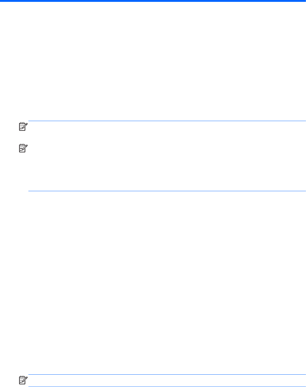
4 Pre-connection checklist
Establishing an RGS connection from a Receiver to a Sender requires that the Local and Remote
Computers be in the correct state. This chapter provides a checklist of items that should be verified
before attempting an RGS connection.
NOTE: This chapter can also be used as a troubleshooting aid. If a connection attempt fails, the
checklists below can be used to help diagnose the problem.
NOTE: The port used by the RGS Receiver is assigned by the Local Computer OS and can vary. The
RGS Sender listens on TCP/IP port 42966. At RGS 5.2.5, the capability was added to specify the port
number used by the RGS Sender. The default Sender port number is 42966, as noted above. The
Sender port number can be changed using the Rgsender.Network.Port property. If this property is used
to change the Sender port number from its default value of 42966, the Sender port number must then
be specified in establishing an RGS connection from the Receiver to the Sender.
Local Computer (Receiver) checklist
Verify the following items on the Receiver computer before attempting to establish a connection.
1. Verify the hostname or IP address of the Remote Computer—Verify that you have the
correct hostname or IP address of the Remote Computer. If the Remote Computer hostname fails to
resolve to the correct IP address, address this problem before continuing.
2. Verify that, from the Local Computer, you can ping the Remote Computer—If
you’re unable to ping the Remote Computer, you won’t be able to establish an RGS connection.
Ping the Remote Computer using the same computer designator you’ll be using to establish an
RGS connection, either the hostname or the IP address of the Remote Computer. Open a
Command window and execute either:
ping hostname
or
ping <IP address>
If no ping reply is received, the Sender computer is unreachable or is not running—resolve this
problem before continuing. If a ping reply is received, the Sender computer is reachable by RGS.
NOTE: Ensure that firewall settings are not preventing the ping command from working.
Local Computer (Receiver) checklist 91

Remote Computer (Sender) checklist
Modification and verification of the Sender state can be performed either by connecting a keyboard,
mouse, and monitor directly to the Remote Computer, or by using Remote Desktop Protocol to log in
remotely to the Remote Computer. In either case, verify each of the following items:
1. OPTIONAL: Ensure RGS Sender licensing is set up—Beginning at RGS 5.2.0, HP
implemented licensing for the RGS Sender. For an overview of RGS licensing, see RGS licensing
on page 14 . For detailed information on RGS licensing, see the HP Remote Graphics Software
Licensing Guide, available at http://www.hp.com/support/rgs_manuals.
NOTE: Step 1 is optional because you can establish a connection from the Receiver to the
Sender without a Sender license. However, as shown in Figure 2-2 Dialog generated when the
RGS Sender is unlicensed on page 14, an error dialog will be displayed in the Remote Display
Window if the Sender license file is missing or invalid. If you don’t set up RGS licensing now, you
can do it after you’ve verified you can establish an RGS connection.
2. Ensure you have a login account on the Remote Computer—When establishing an
RGS connection, the Remote Computer will prompt you for a user name and password. Ensure
that you have a login account on the Remote Computer.
3. Verify the Remote Computer login account does not have a blank password—The
Remote Computer will not allow a connection for any account with a blank or undefined
password. Any accounts on the Remote Computer used for connection by the Local Computer must
have password protection.
4. OPTIONAL: Disable Guest login access—By default, Windows allows any user who can
access a computer over the network to login with Guest access. Because this is a potential security
issue, HP recommends that you disable Guest logins on the Remote Computer. To disable this
policy, open the "Control Panel", selecting "Administrative Tools", selecting "Local Security
Policy", expanding the "Local Policies", expanding "Security Options", and setting "Network
access: Sharing and security model for local accounts" to "Classic – local users authenticate as
themselves". For more information on this topic, go to:
http://support.microsoft.com/kb/103674
5. Ensure that the RGS Sender is running on the Remote Computer—This can be done
on Windows as follows:
a. Click Start
b. Right-click My Computer
c. Select Manage from the menu.
d. In the Computer Management console, click the + sign to expand Services and
Applications and select Services. The service Remote Graphics Sender should be
listed as Started.
6. Verify that the rgdiag.exe diagnostics tool passes all tests on the RGS Sender on
Windows—This tool may be run any time after Sender installation. Refer to Using the RGS
Diagnostics Tool on Windows on page 80 for information on running this tool.
92 Chapter 4 Pre-connection checklist

7. Network Interface binding—Beginning with RGS 5.4.0 the Sender defaults to listening to
multiple network interfaces if the computer is so equipped. If the Remote Computer has multiple
network interfaces, the Sender will dynamically add or remove network interfaces without
restarting the Sender. This topic is expanded considerably in Network Interface binding on the
Sender on page 94 .
8. Linux Sender machine name and IP address—The default on Linux is to bind the machine
name to the following loopback interface in the /etc/hosts file:
127.0.0.1 blade2 localhost.localdomain
The RGS Sender will not accept remote connections with this configuration. Edit the /etc/hosts file
and bind the machine name to its proper IP address as follows:
127.0.0.1 localhost localhost.localdomain
88.1.89.122 blade2 blade2.datacenter.com
For Linux systems with multiple network interfaces, each IP address must be listed in the /etc/hosts
file for example:
192.168.89.122 blade2 blade2.datacenter.com
192.168.90.111 blade2b blade2b.datacenter.com
9. User-started X environments do not reliably support outside connections—Users
who manually start X desktops (such as with startx) from the console command line will find that
outside access attempts may not properly connect or be authenticated. This stems primarily from
incomplete PAM session management and permissions to the console. Users should avoid this
condition, and achieve login management through the display manager launched in init-level 5 of
the system.
10. Windows APIPA (Automatic Private IP Addressing)—APIPA can cause the RGS Sender
to open sockets on private IP addresses. This can occur, for example, if the Sender computer is
unable to connect to a DHCP server. Because the private IP addresses are not visible to the RGS
Receiver, RGS connections will not work. You can verify if the Sender is using private IP addresses
by typing the following in a command window:
netstat -n -a
If the IP address associated with the Sender port (listening port 42966) is private, APIPA is the
likely cause. For more information on this topic, go to:
http://support.microsoft.com/kb/220874
11. Log out—If you do log into the Remote Computer to verify any of the above items, ensure that
you log out when you’re done.
Remote Computer (Sender) checklist 93
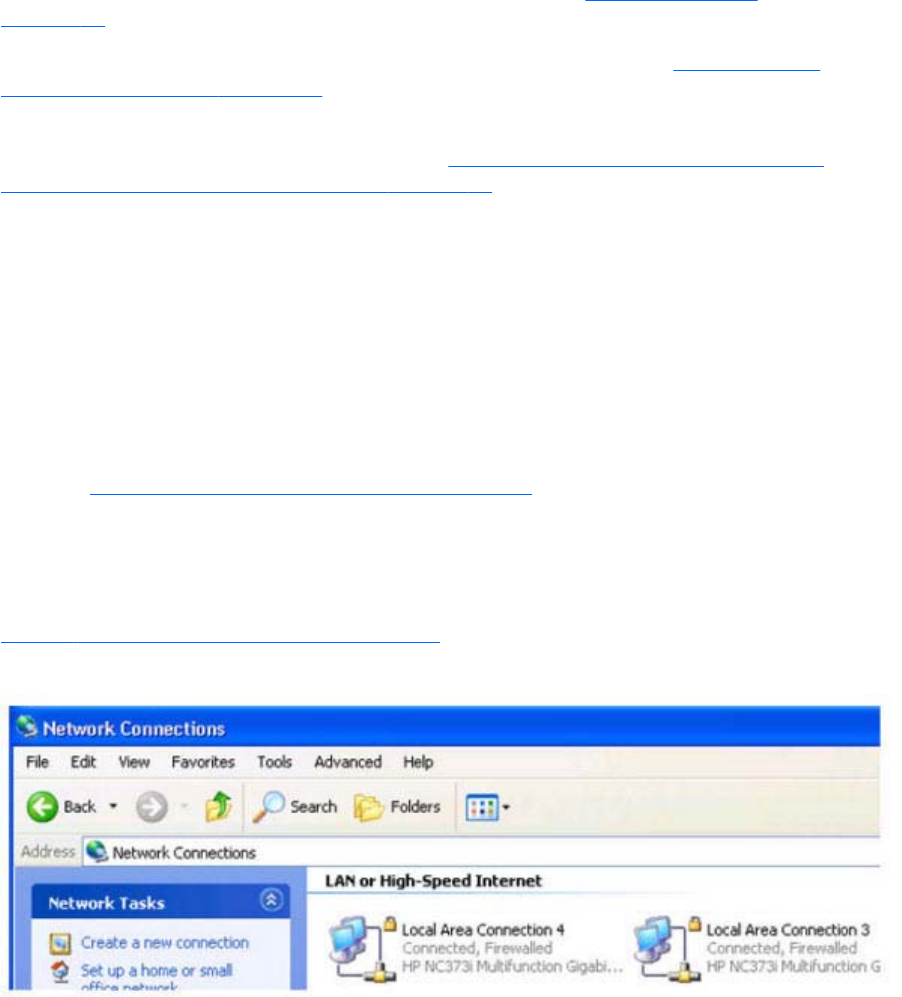
Network Interface binding on the Sender
If the Remote Computer has multiple network interfaces, beginning with RGS 5.4.0 the Sender defaults
to “listening” on all network interfaces. If this is undesirable, the previous behavior can be restored by
manually configuring the network interface binding properties.
There are four methods to deal with multiple network interfaces:
1. Allow the Sender to listen on all network interfaces and dynamically add and remove network
interfaces, the default behavior of RGS 5.4.0 and beyond. See the Networking support
on page 16 section for more detail.
2. Manually reconfigure which of the two network interfaces RGS binds to—see Manual Network
Interface reconfiguration on page 94.
3. Use the RGS Sender network interface binding properties (introduced at RGS 5.1) to explicitly
specify which network interface RGS binds to—see Network Interface reconfiguration using the
Sender network interface binding properties on page 97.
4. Disable one of the network interfaces and restart the Sender—the Sender will then bind to the
enabled network interface. The disadvantage of this method, of course, is that one of the network
interfaces will no longer be usable.
Methods 2 and 3 are described in the next two sections.
Manual Network Interface reconfiguration
To manually configure which network interface the Sender binds to, set the Sender property
Rgsender.Network.IsListenOnAllInterfacesEnabled=0 overriding the default which is to listen on all
interfaces. See Network Interface binding properties on page 204, for more detail. If the Sender
property Rgsender.Network.IsListenOnAllInterfacesEnabled=0 then the RGS Sender binds to the
network interface specified by the Rgsender.Network.Interface.<x>.IsEnabled=1 property. To determine
the IP address of a network interface, perform the following steps on the Remote Computer:
1. To view both network interfaces, click Start > Control Panel > Network Connections (see
Figure 4-1 Viewing network interfaces on page 94).
Figure 4-1 Viewing network interfaces
94 Chapter 4 Pre-connection checklist
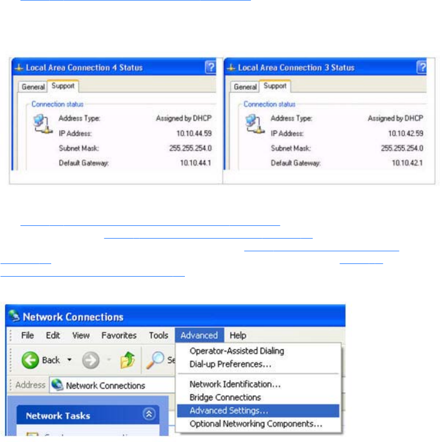
2. Double-click each LAN icon and the Support tab, which displays the network interface IP address
(see Figure 4-2 Network Interface IP addresses on page 95). While this provides the IP address
of each network interface, it does not indicate which network interface is considered the “first
network interface”.
Figure 4-2 Network Interface IP addresses
3. To determine which is the first (0th) network interface, click Advanced > Advanced Setting
(see Figure 4-3 Determining the first network interface on page 95). The Advanced Settings
dialog is displayed (see Figure 4-4 Advanced Settings dialog on page 96). The “first network
interface” is listed at the top in the Connections box. In Figure 4-4 Advanced Settings dialog
on page 96, the first network interface is Local Area Connection 3, which (from Figure 4-2
Network Interface IP addresses on page 95) has an IP address of 10.10.42.59.
Figure 4-3 Determining the first network interface
Network Interface binding on the Sender 95
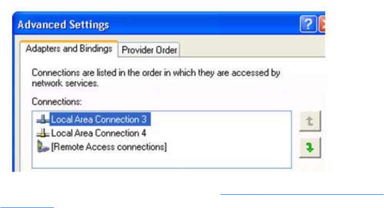
Figure 4-4 Advanced Settings dialog
The arrows to the right of the Connections box in Figure 4-4 Advanced Settings dialog
on page 96 can be used to change the order of the network interfaces and, therefore, which
network interface will be used by the RGS Sender. In the above example, the RGS Sender will use
Local Area Connection 3 with an IP address of 10.10.42.59.
To establish a connection from the RGS Receiver to the blade workstation, enter a hostname or IP
address in the HP Remote Graphics Receiver box. If you enter a hostname instead of an IP
address, it is possible the hostname will resolve to the IP address of an incorrect network interface.
This could be caused by a number of factors, including how your DHCP and DNS servers are
configured.
If the hostname resolves to the IP address of an incorrect network interface, you can either:
●Enter the network interface IP address (instead of hostname) in the HP Remote Graphics
Receiver box.
●Reconfigure your DHCP and DNS servers so that the hostname resolves to the IP address of
the correct (first) network interface.
96 Chapter 4 Pre-connection checklist
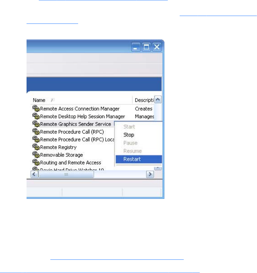
●Use the Nslookup command to determine the IP address that the hostname resolves to. Then,
using the arrow buttons to the right of the Connections box on the Advanced Settings screen
(see Figure 4-4 Advanced Settings dialog on page 96) change the first network interface to
correspond with the IP address returned by Nslookup. After performing this step, you must
either reboot the computer, or restart the RGS Sender (see Figure 4-5 Restarting the RGS
Sender on page 97).
Figure 4-5 Restarting the RGS Sender
Network Interface reconfiguration using the Sender network
interface binding properties
At RGS 5.1, several new Sender properties were added to allow the administrator to configure which
network interface(s) the RGS Sender will listen to for connection requests. For a description of these
properties, refer to Network Interface binding properties on page 204.
Figure 4-6 Network Interface binding order numerical sequence on page 98 shows how the two
network interfaces can be referenced in numerical sequence in their binding order. The network
interface binding properties permit specification of which network interface (either 0 or 1) the RGS
Sender will listen to for connection requests. For example, using the Rgsender.Network.Interface.
1.IsEnabled property, an administrator can specify that the RGS Sender will listen for connection
Network Interface binding on the Sender 97
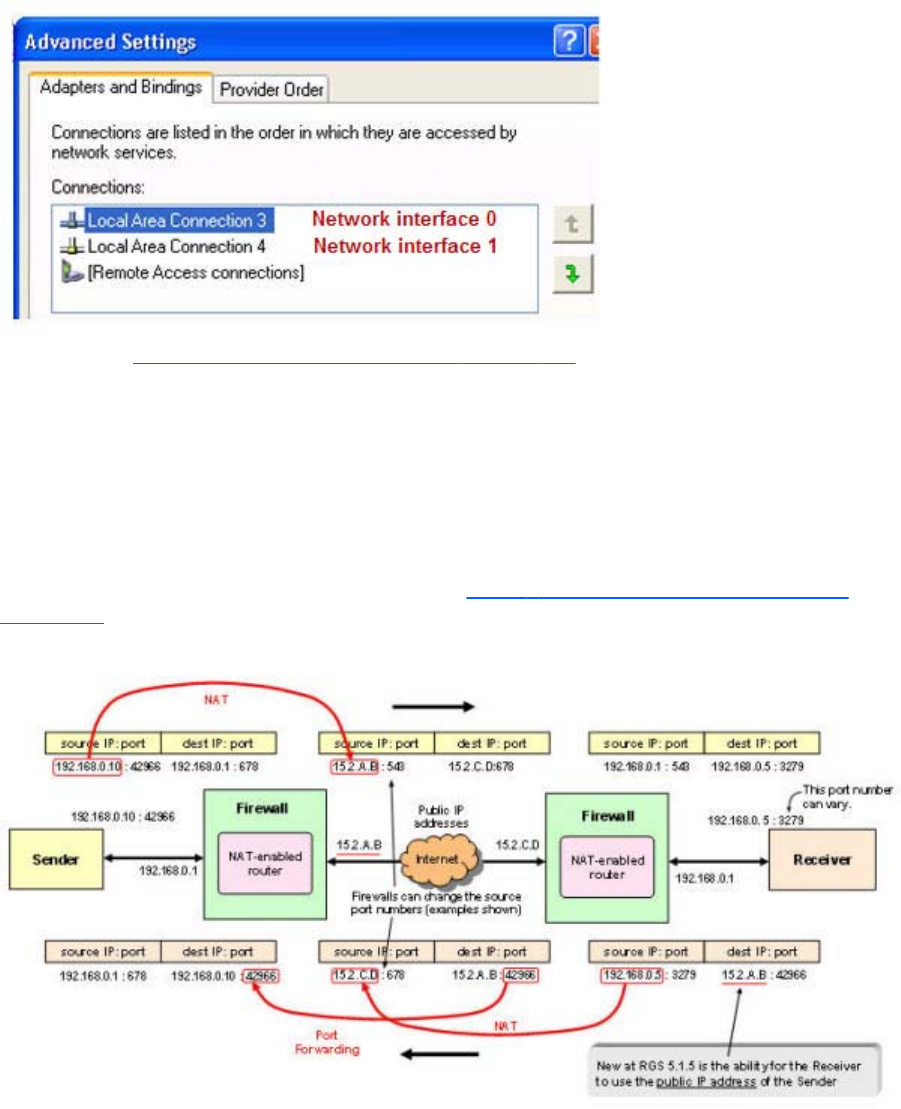
requests on network interface 1 (corresponding to Local Area Connection 4), even though network
interface 1 is the second network interface in binding order.
Figure 4-6 Network Interface binding order numerical sequence
Again, refer to Network Interface binding properties on page 204 for a description of these
properties.
Using RGS through a firewall
New at RGS 5.1.5 is the ability for the Receiver to use the public IP address of the Sender. This feature
has been added to allow RGS to be used through a simple firewall. To take advantage of this feature,
the Sender and Receiver firewalls must both support NAT (Network Address Translation). In addition,
the Sender firewall must support port forwarding (see Figure 4-7 RGS operation through a firewall
on page 98).
Figure 4-7 RGS operation through a firewall
98 Chapter 4 Pre-connection checklist

NOTE: The port used by the RGS Receiver is assigned by the Local Computer OS and can vary. The
RGS Sender listens on TCP/IP port 42966. At RGS 5.2.5, the capability was added to specify the port
number used by the RGS Sender. The default Sender port number is 42966, as noted above. The
Sender port number can be changed using the Rgsender.Network.Port property as described in
Network Interface binding properties on page 204. If this property is used to change the Sender port
number from its default value of 42966, the Sender port number must then be specified in establishing
an RGS connection from the Receiver to the Sender.
Using RGS through a firewall 99

5Using RGS
This chapter describes how to use RGS to establish a connection from a Local Computer to a Remote
Computer, including:
●Using RGS in Normal Mode
●Functionality and use of the Receiver Control Panel
●Setup Mode
●Remote Display Window Toolbar
●Remote Computer monitor blanking
●Linux connection considerations
●RGS login methods
●Receiver command line options
●Collaborating
100 Chapter 5 Using RGS
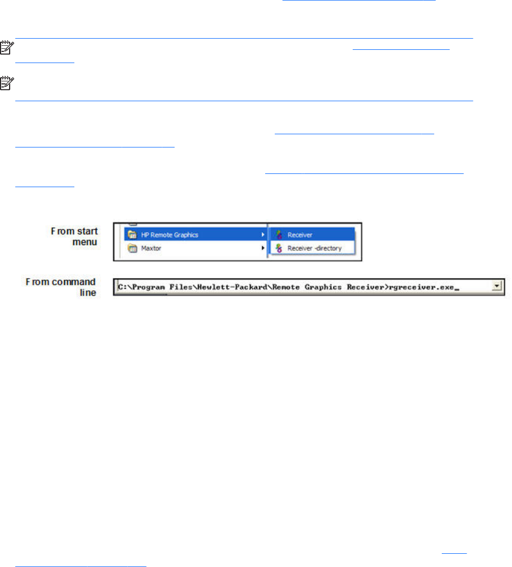
Using RGS in Normal Mode
Normal Mode is one of the two RGS operating modes—see RGS operating modes on page 26.
Normal Mode is the simplest means of establishing a connection—you enter the IP address or hostname
of the Remote Computer in the Local Computer Receiver Control Panel, and click Connect.
NOTE: The second RGS operating mode, Directory Mode, is described in Using Directory Mode
on page 170 .
NOTE: The RGS Sender listens on TCP/IP port 42966. The port used by the RGS Receiver is
assigned by the Local Computer OS and can vary.
Before attempting to connect to a particular Remote Computer for the first time, HP recommends that
you verify that the Remote and Local Computers satisfy the Pre-connection checklist on page 91 . The
Pre-connection checklist on page 91 can also be used as a troubleshooting aid if a connection attempt
fails. After verifying the preconnection checklist, start the Receiver on the Local Computer. This can be
done from the start menu or from the command line (see Figure 5-1 Starting the Receiver on Windows
on page 101).
Figure 5-1 Starting the Receiver on Windows
The RGS Receiver supports the following command line options for the Windows executable,
rgreceiver.exe, and the Linux executable, rgreceiver.sh:
[-config [filename]]
[-directory [file]]
[-nosplash]
[-v | -ver | -version]
[-h | -help | -?]
-Rgreceiver.propertyname=value
-config filename—Specifies the name of a RGS Receiver configuration file to use.
-directory [file]—Starts the Receiver in Directory Mode. If the optional file path is specified, the
file is opened and used to look up the Remote Computers assigned to the user. If a file is not specified,
the user is prompted to enter a path to the directory file. For information on Directory Mode, see Using
Directory Mode on page 170.
-nosplash—Disables display of the splash screen when the Receiver starts.
[-v | -ver | -version]—Displays the Receiver version information.
Using RGS in Normal Mode 101
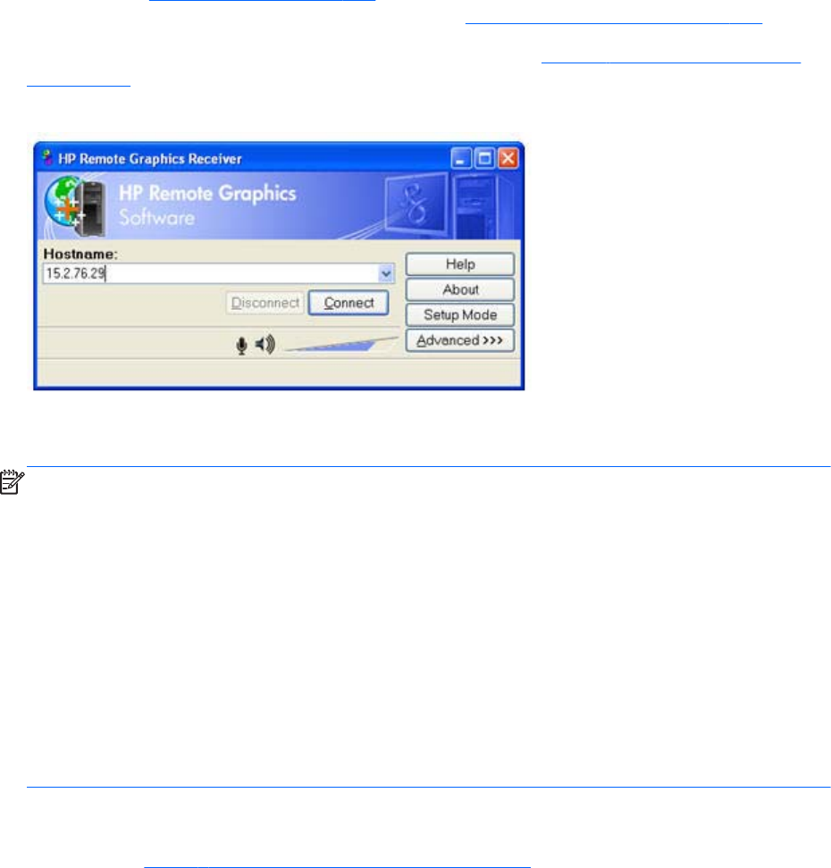
[-h | -help | -?]—Displays the Receiver command line options that are listed on this page
-Rgreceiver.propertyname=value—Can be used to specify one or more RGS Receiver
properties. See RGS properties on page 174 for general information on RGS properties. For
information specifically on RGS Receiver properties, see RGS Receiver properties on page 176.
After the Receiver starts, you’ll see the Receiver Control Panel (see Figure 5-2 Receiver Control Panel
on page 102).
Figure 5-2 Receiver Control Panel
To create an RGS connection, enter the hostname or IP address of the Remote Computer in the
Hostname dialog box, and then press Enter or click Connect.
NOTE: At RGS 5.2.5, the capability was added to specify the port number used by the RGS Sender.
The default Sender port number is 42966. The Sender port number can be changed using the
Rgsender.Network.Port property. If this property is used to change the Sender port number from its
default value of 42966, the Sender port number must then be specified in the above Hostname dialog
box, in either of the following formats:
hostname:port number
IP address:port number
For example, if the Rgsender.Network.Port property is used to change the Sender port to 42970, the
Sender IP address in the figure above would need to be modified to include the port number, as
follows:
15.2.76.29:42970
Provide a username and password, as prompted. If the connection succeeds, the Remote Display
Window will be displayed on the Local Computer, showing the desktop session of the Remote
Computer (see Figure 5-3 Remote Display Window on page 103).
102 Chapter 5 Using RGS
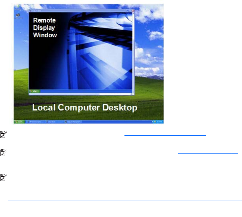
Figure 5-3 Remote Display Window
NOTE: If the connection attempt fails, refer to the Pre-connection checklist on page 91 , for a list of
conditions which must be met in order for a connection to be established.
NOTE: If your RGS Sender is not yet licensed, the error dialog in Section RGS licensing on page 14
will be displayed in the Remote Display Window. For information on Sender licensing, see the HP
Remote Graphics Software Licensing Guide, available at http://www.hp.com/support/rgs_manuals.
NOTE: On Linux, The Receiver Control Panel will not stay on top of other windows in the desktop,
and can therefore get lost. Also, for session managers that support multiple desktops, the Receiver
control panel will not, by default, show up in all desktops. Refer to Setup Mode on page 104 to
understand how to raise the Receiver Control Panel to the top of the window stack.
In Normal Mode, the Local Computer can connect to only one Remote Computer at a time, as
described in One-to-one connection on page 17 If an attempt is made to connect to a second Remote
Computer using the Receiver Control Panel, the connection to the first Remote Computer is terminated.
Receiver Control Panel
Now that a connection has been established, the Receiver Control Panel is described in more detail.
The Receiver Control Panel is used to perform the following tasks:
●Establish a connection: To establish a connection to a Remote Computer, enter the hostname
or IP address of the computer in the Hostname field. Press Enter or click the Connect button to
connect to the Remote Computer. The selector on the right side of the text box displays a history of
previously connected computers that can be selected.
●Close a connection: To close a connection, press the Disconnect button.
●Enter Setup Mode: To enter Setup Mode, press the Setup Mode button. In Setup Mode, the
Receiver suspends mouse and keyboard input to the Remote Computer, allowing the user to use
Using RGS in Normal Mode 103

the mouse and keyboard to interact with local Remote Display Windows. See Setup Mode
on page 104 for more information.
●View advanced operations: Click Advanced>>> to view the tabs which provide access to
many of the advanced capabilities of RGS.
●Display help: Click Help to display the online help. On Linux, the online help is displayed
separately in a web browser, such as Mozilla. On Windows, the online help is displayed using
the CHM file viewer hh.exe.
●Display program information: Click About to display RGS program and copyright
information.
The Receiver Control Panel contains a status bar at the bottom of the window. The status bar provides
information that describes the current state of the RGS Receiver. For example, it displays the messages
“connection in progress”, “connection succeeded”, and “connection failed.” The status bar can be
useful in diagnosing connection problems because it also displays the general reason for a connection
failure, such as “Authorization Failed” or “Authentication Failed”.
Setup Mode
Depending on how you configure RGS on the Local Computer, the Remote Display Window may cover
the entire Local Computer monitor. Furthermore, the Remote Display Window may be set to borderless
—therefore, the window won’t have the title bar and borders that normally allow the window to be
moved, minimized, and resized. Such a configuration raises a number of questions, including:
●How do you move or resize the window absent a title bar and borders?
●If multiple Remote Display Windows are covering each other, how do you select a particular
Remote Display Window to view?
Complicating the situation is that all keyboard and mouse events in the Remote Display Window are
sent to the Remote Computer for processing. Therefore, the keyboard and mouse cannot be readily
used to interact with the locally-displayed Remote Display Window.
To address this situation, RGS provides Setup Mode. In Setup Mode, transmission of keyboard and
mouse events to the Remote Computer is suspended—instead, the keyboard and mouse can be used to
interact with the Remote Display Window on the Local Computer. In Setup Mode, you can perform a
number of operations, including:
●Move a borderless Remote Display Window
●Raise a particular Remote Display Windows that is being obscured by another Remote Display
Window
NOTE: In Normal Mode, only a single Remote Display Window can be displayed on the Local
Computer. Displaying Multiple Remote Display Windows on the Local Computer requires using
Directory Mode (see Using Directory Mode on page 170).
104 Chapter 5 Using RGS
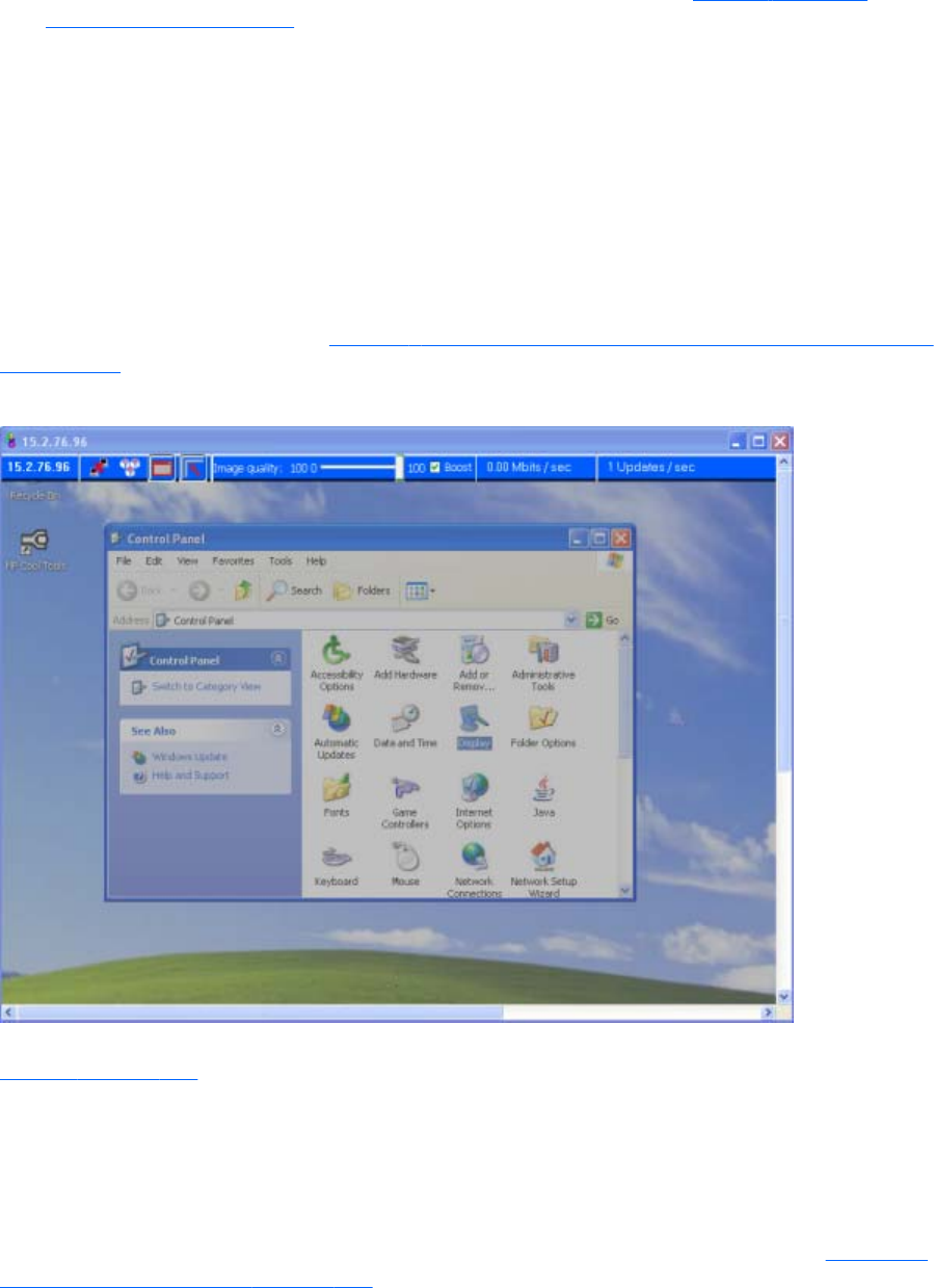
Setup Mode can be activated in two ways:
1. By clicking the Setup Mode button on the Receiver Control Panel (see Figure 5-2 Receiver
Control Panel on page 102). This presumes, of course, that the Receiver Control Panel is visible.
2. By typing a special key sequence on the keyboard, called a hotkey sequence.
The hotkey sequence method of activating Setup Mode is required in situations where, for example, the
Remote Display Window is borderless, and is covering the entire Local Computer monitor, including the
Receiver Control Panel. Because the Receiver Control Panel is obscured, its Setup Mode button is
inaccessible. The default hotkey sequence to enter Setup Mode is:
Shift press, space press, space release
When the Receiver detects this key sequence, it does not send the key sequence to the Remote
Computer—instead, the Receiver activates Setup Mode on the Local Computer, as denoted by dimming
of the Remote Display Window (see Figure 5-4 Dimming of the Remote Display Window in Setup Mode
on page 105).
Figure 5-4 Dimming of the Remote Display Window in Setup Mode
The default hotkey sequence can be changed using the Hotkeys tab in the Receiver Control Panel (see
Hotkeys on page 156). As long as the Shift key is held down (following the Shift press, space press,
and space release hotkey sequence used to enter Setup Mode), Setup Mode remains active. When the
Shift key is released, Setup Mode exits. In contrast, the Setup Mode button on the Receiver Control
Panel toggles the state of Setup Mode each time the user clicks on the button.
If Setup Mode is activated by the hotkey sequence (as opposed to the Setup Mode button), and you
have multiple Remote Display Windows on your computer, you can bring up the Remote Display
Window selection dialog to view a thumbnail image of each Remote Display Window (see Starting the
Receiver in Directory Mode on page 172)
Using RGS in Normal Mode 105
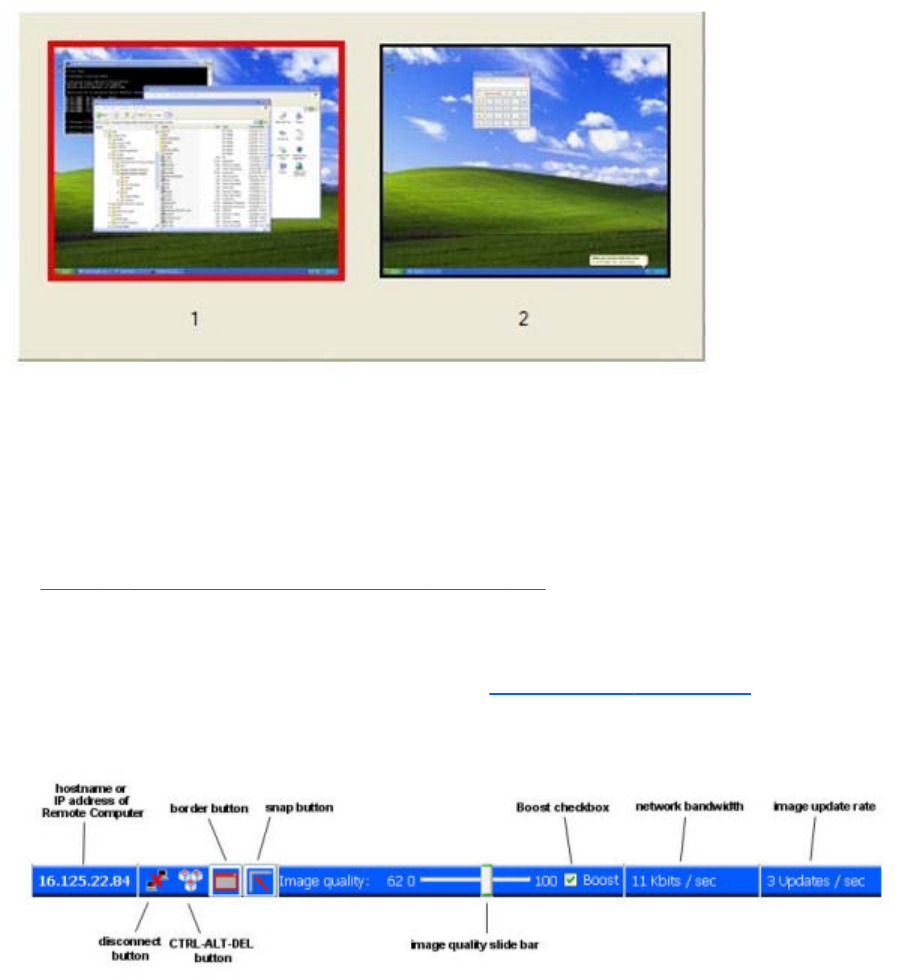
Figure 5-5 Remote Display Window selection dialog
The Remote Display Window selection dialog is only displayed in Directory Mode—this is the mode
that supports multiple Remote Display Windows.
Remote Display Window Toolbar
The Remote Display Window Toolbar provides information on the RGS connection, and allows several
RGS parameters to be controlled. The toolbar is positioned at the top of the Remote Display Window
(see Figure 5-6 Remote Display Window Toolbar on page 106) and is toggled on and off by pressing
the H key while in Setup Mode. In this particular case, Setup Mode can be entered by either method—
the Setup Mode button or the hotkey sequence—and the H key can be used to display the toolbar.
Introduced at RGS 5.4.5, a new feature Auto show toolbar, allows the Remote Display Window
Toolbar to be automatically displayed. See the Receiver General options on page 119 tab for more
information.
Figure 5-6 Remote Display Window Toolbar
The Remote Display Window Toolbar provides the following:
●hostname—The hostname or IP address of the Remote Computer
●disconnect button—Disconnects the current RGS session
●CTRL-ALT-DEL button—Sends the CTRL-ALT-DEL key sequence to the Remote Computer. Some
key sequences, such as CTRL-ALT-DEL, are trapped by the Local Computer, and therefore are not
forwarded to the Remote Computer. This button allows the user to send a CTRL-ALT-DEL sequence
to the Remote Computer without using the keyboard.
106 Chapter 5 Using RGS

●Borders button—Adds or removes window borders and decorations on the Remote Display
Window.
●Snap button—When selected, this option causes the Remote Display Window to snap to the
edges of the monitor whenever the boundaries of the window are within 30 pixels of any edge of
the monitor.
●Image quality slide bar—Sets the image quality and, therefore, the amount of compression.
Higher image quality reduces the amount of compression, and therefore consumes greater
network bandwidth.
●Boost checkbox—When checked, will improve (boost) image quality for certain types of
images, namely those images containing significant amounts of text or lines. Because of the high
contrast ratio between adjacent pixels, such images often don’t compress well. When the Boost
checkbox is checked, such high contrast cases will be compressed in a manner to better preserve
their visual quality, but at the possible expense of higher network bandwidth and/or lower image
update rates. HP recommends that you experiment with different settings of the image quality slide
bar and the Boost checkbox to find the optimal settings for your environment.
The Boost checkbox was added beginning with RGS 5.2.6, and requires that both the RGS
Sender and Receiver be version 5.2.6 or later. The Boost setting can also be controlled by the
Rgreceiver.ImageCodec.IsBoostEnabled Receiver property.
●Network bandwidth—Displays the current network bandwidth consumed by this connection.
●Image update rate—Displays the number of image updates per second for this connection.
Remote Computer monitor blanking operation
Monitor blanking on the Remote Computer is provided for security, so that the primary user’s desktop
session on the Remote Computer is not visible if a monitor is connected to the Remote Computer.
The default behavior is that the Remote Computer monitor will blank to black when the user connects
and logs in. The Remote Computer monitor will unblank when the user disconnects or logs out. Below
are several additional details on monitor blanking on HP Personal Workstations:
●The one element on the monitor that does not go blank is the cursor.
●Blanking can take up to two seconds from the time the primary user logs in or reconnects until the
time that the monitor is actually blanked.
●The HP Personal Workstations also block input from a directly-connected keyboard and mouse
when monitor blanking is occurring. When keyboard or mouse input is received by the Remote
Computer, the monitor will enter the display powersave mode, and the cursor will be blanked as a
result.
●An exception to input blocking is the CTRL-ALT-DEL key sequence. When this sequence is received
by the Remote Computer from a directly-connected keyboard, the Remote Computer desktop will
display the login dialog on the Local Computer. The Remote Computer monitor will remain blank
while this occurs but the monitor will exit its powersave mode, and keyboard input will become
unblocked until this dialog is dismissed.
NOTE: Remote Computer monitor blanking is not supported if the remote computer is a virtual
machine (e.g., VMWare ESX, Citrix Xen, etc).
Using RGS in Normal Mode 107
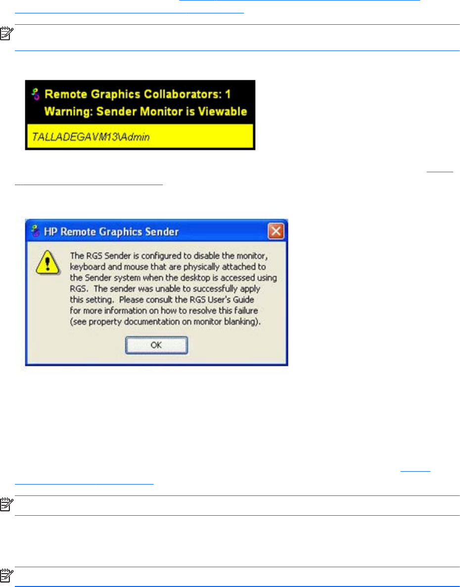
If monitor blanking is enabled but the Remote Computer is unable to blank the display (because, for
example, the computer is not one of the supported computers listed previously), a warning dialog is
displayed on the Local Computer (see Figure 5-7 Local Computer warning dialog if the Remote
Computer is unable to blank its monitor on page 108).
NOTE: Linux screen blanking functionality is not supported on Dual-Monitor systems unless NVIDIA
TwinView is in use.
Figure 5-7 Local Computer warning dialog if the Remote Computer is unable to blank its monitor
Click Warning: Sender Monitor is Viewable to view the associated message dialog (see Figure
5-8 Message Dialog on page 108).
Figure 5-8 Message Dialog
The Remote Computer monitor blanking feature can be disabled by setting the following Sender
property to 0 (false).
Rgsender.IsBlankScreenAndBlockInputEnabled
If this property is set to 0, monitor blanking will be disabled, meaning that a monitor connected to the
Remote Computer will display the user’s desktop session. Furthermore, because monitor blanking is
disabled, the warning dialog will not be displayed. For more details on this property, see Sender
general properties on page 200.
NOTE: RGS 5.4.8 adds support for screen blanking on Linux-based senders.
Linux connection considerations
NOTE: The Switch User functionality added to RHEL6 is not supported by RGS.
108 Chapter 5 Using RGS
Full-screen crosshair cursors
Certain applications that use large crosshair cursors (for example, Dassault Systemes ICEM Surf uses a
full-screen crosshair cursor) will not display correctly on the Receiver. Full-screen crosshair cursors can
be disabled by typing the following in a terminal window:
X11xprop -root -remove _SGI_CROSSHAIR_CURSOR
This will force the application to use an X cursor, which will display correctly on the Receiver.
Gamma correction on the Receiver
The color on a 3D application on the Sender can look incorrect when displayed on a Receiver. This is
because the gamma of the Local Computer monitor may not match the gamma of the Remote Computer
monitor. To correct this, any tool that will adjust the gamma for a display can be used. Some tools will
adjust the gamma for the entire monitor, while others will adjust the gamma on a per-window basis.
Per-window tools that can be used to adjust only the Receiver window will provide the best results.
Black or blank connection session with the Linux Sender
Connection to an X server that is configured with less than 24-bit or 32-bit default visuals (depending
on the graphics device) will cause the Linux Sender to generate a black or blank connection screen. For
example, some default installations may configure a 16-bit visual in /etc/X11/xorg.conf after the
installation. Reconfiguring the X server to serve 24-bit (or 32-bit) default visuals, and restarting the X
server will usually fix the black or blank connection situation.
Linux connection considerations 109
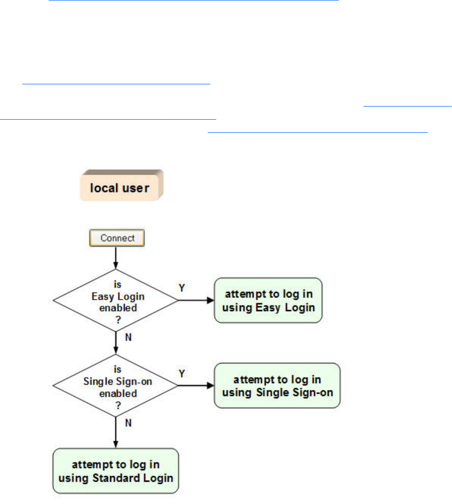
RGS login methods
RGS provides three methods for the local user to log into a Remote Computer:
●Standard Login—supported on Windows and Linux Senders. For an overview of Standard
Login Establishing an RGS connection using Standard Login on page 21.
●Easy Login—supported on Windows XP Professional and Windows 7 Senders on HP blade
workstations. Beginning with RGS 5.4.8, Easy Login is also supported on Linux Senders.
●Single Sign-on—supported on Windows XP Professional and Windows 7 Senders on HP blade
workstations and HP personal workstations. For an overview of Single Sign-on and Easy Login, see
Single Sign-on and Easy Login on page 23. Single Sign-on is not supported on Linux senders.
The log in method that is used is dependent on how the Sender was installed—see Figure 3-4 Dialog to
enable Single Sign-On or Easy Login on page 60. If neither Easy Login nor Single Sign-on was enabled
during installation, Standard Login is used (see Figure 5-9 Log in selection flowchart on page 110).
Figure 5-9 Log in selection flowchart
Each method is described below.
110 Chapter 5 Using RGS
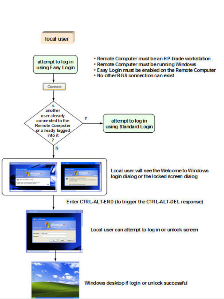
Standard Login
Standard Login is the process by which a local user attempts to connect to a Remote Computer that has
neither Single Sign-on nor Easy Login enabled.
See the tabloid page (the last page of the PDF version) of this guide for a diagram of the Standard
login process.
Easy Login
The Easy Login flowchart is shown in Figure 5-10 Easy Login process on page 111. If the Easy Login
conditions are met, the RGS connection authentication step is skipped, and the local user is presented
either with the Welcome to Windows login dialog or the locked screen dialog.
Figure 5-10 Easy Login process
RGS login methods 111
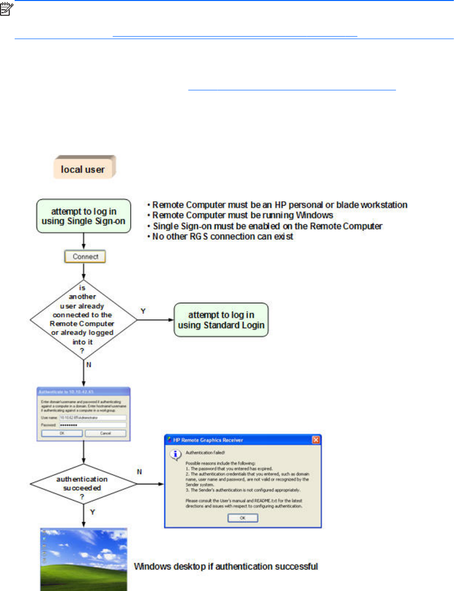
NOTE: There are several Sender setup issues that can prevent an Easy Login connection to the RGS
Sender. The RGS Diagnostics Tool programmatically detects several of these issues, and suggests
possible solutions. See Using the RGS Diagnostics Tool on Windows on page 80 for more details.
Single Sign-on
The Single Sign-on flowchart is shown in Figure 5-11 Single Sign-on process on page 112. If the
Single Sign-on conditions are met, the user authenticates the RGS connection, and the Windows log in
or unlock step is skipped. The user is presented with the Windows desktop following RGS connection
authentication.
Figure 5-11 Single Sign-on process
112 Chapter 5 Using RGS
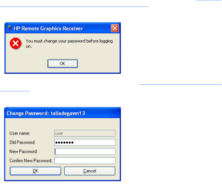
Changing your password
In RGS 5.0 and earlier, attempting to make a connection with an expired password would generate an
Authentication failed! error message. In this situation, the user would either need direct access to the
Remote Computer to change the password, or would need to call IT to have the password changed.
Starting at RGS 5.1, you can change an expired password from the RGS Receiver. If you enter an
expired password, you will see a dialog stating that the password must be changed (see Figure 5-12
Dialog indicating that the password must be changed on page 113).
Figure 5-12 Dialog indicating that the password must be changed
After clicking OK, you’ll see the Change Password dialog (see Figure 5-13 Change Password dialog
on page 113).
Figure 5-13 Change Password dialog
Enter the requested information to change your password.
Changing your password 113
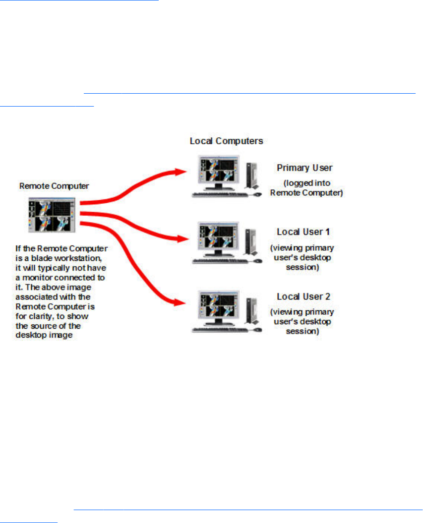
Collaborating
RGS enables the primary user to share his or her desktop session with several users simultaneously (see
One-to-many connection on page 19). This feature can be used in a variety of collaborative scenarios
including classroom instruction, design reviews, and technical support.
Creating a collaboration session
A collaboration session is created when one or more users are authorized by the primary user to
connect to the primary user’s desktop session. This allows all users to view and interact with the primary
user’s desktop (see Figure 5-14 Multiple local users can view and interact with the primary user's
desktop on page 114).
Figure 5-14 Multiple local users can view and interact with the primary user's desktop
The user currently controlling the mouse and keyboard is called the floor owner. Only one user, the
floor owner, can interact with the desktop at a time. To transition the floor owner, the current floor
owner must cease using the keyboard or mouse for a short period of time (0.5 seconds). If another user
uses the mouse or keyboard while the current floor owner is inactive during this .5 second period, floor
ownership transfers to the new user.
In a collaboration session, the shape of the local cursor is modified for the floor owner. For the other
remote users, the local cursor is left unchanged, and a remote cursor is displayed in the Remote Display
Window.
Use of the mouse and keyboard by collaboration users can be disabled by the primary user using the
Sender GUI (see Figure 5-15 Disabling of the local users’ mice and keyboards by the primary user
on page 115). Authorized local users will still be able to view the primary user’s desktop, but will be
unable to interact with it.
114 Chapter 5 Using RGS
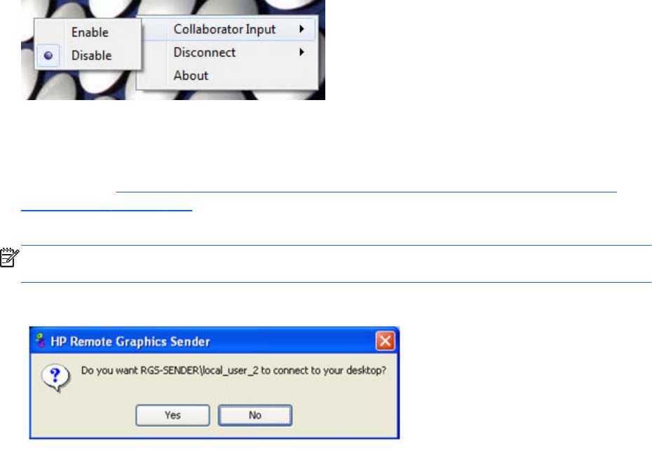
Figure 5-15 Disabling of the local users’ mice and keyboards by the primary user
Connection between a Local Computer and a Remote Computer is permitted only if the primary user
allows the connection and if all users have unique login accounts for the remote computer. Users may
not share the same login account. A question dialog, stating the domain and user name of the local
user attempting a connection, is displayed on the Remote Computer desktop when a local user attempts
to connect (see Figure 5-16 Primary user dialog to authorize a local user to connect to the primary
user’s desktop on page 115). All currently connected local users will also see this dialog because they
are currently viewing the Remote Computer desktop.
NOTE: One-to-many (collaboration) requires a unique login account with credentials on the sender
for each participant.
Figure 5-16 Primary user dialog to authorize a local user to connect to the primary user’s desktop
The different cases for establishing a collaborative session are:
●If no one is logged into the Remote Computer desktop (in other words, there is no primary user),
all authenticated users are connected, and can view the Windows login desktop. However, when
any one user logs into the Remote Computer desktop (and, therefore, becomes the primary user),
all other authenticated users (who are viewing the Windows login desktop) will be disconnected
as a security precaution.
●If the primary user authorizes a connection from a local user, the new user connects to the Remote
Computer and can view its desktop.
●If the primary user does not allow the connection, the new user will be unable to connect.
●On Windows, if the primary user disconnects, the desktop is locked, but the Receivers will remain
connected.
●On Linux, if the primary user disconnects, the desktop is locked, and all users are disconnected.
●If the local user connecting to the primary user’s computer is the same user as the primary user, the
collaboration dialog is not displayed, and the connection is allowed.
The Sender desktop icon in the system application tray displays the status of connections. The icon
animates when Receivers are connected.
All Receivers can be easily disconnected from the HP Remote Graphics icon located in the system tray
or from the Sender GUI by right-clicking on the icon or GUI. This is useful when hosting collaborative
session, such as in a classroom environment, and the session ends.
Collaborating 115
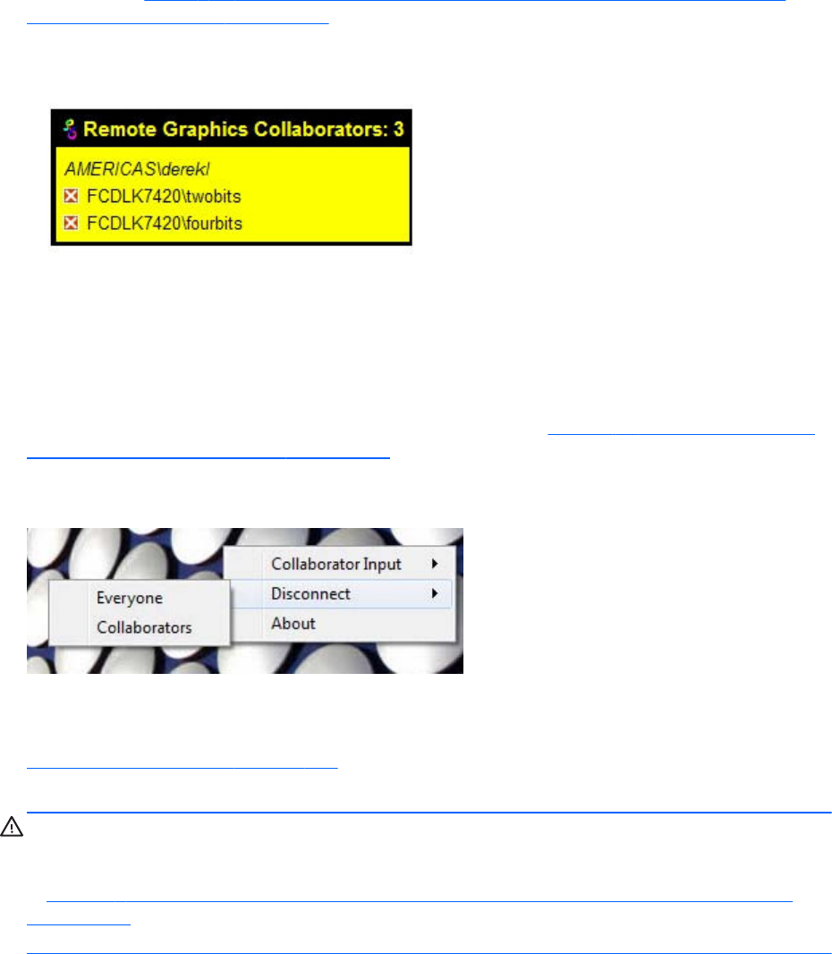
Collaboration notification dialog
The Windows Sender displays a collaboration notification dialog when collaboration users are
connected. This Sender-created dialog appears in each Remote Display Window that is connected to
the Sender. The dialog displays a list of domain\usernames for each user connected to the Remote
Computer (see Figure 5-17 Collaboration notification dialog displayed on the Sender and in each
Remote Display Window on page 116).
Figure 5-17 Collaboration notification dialog displayed on the Sender and in each Remote Display
Window
When the collaboration notification dialog is displayed, it indicates there are multiple connections to
the Remote Computer desktop. Primary and collaboration users are identified using different fonts in the
notification dialog. The primary user is italicized and listed first. Collaboration usernames follow, and
are displayed using a normal font. The figure above shows three active connections, one a primary
user and the other two collaboration users. A small button with an “X” is displayed next to all
collaboration usernames. Pressing this button disconnects the corresponding collaboration user.
All collaboration users can be disconnected using the Sender GUI. Figure 5-18 Windows Sender GUI
to disconnect collaboration users on page 116 shows the Windows Sender GUI selection that can be
used to disconnect collaboration users.
Figure 5-18 Windows Sender GUI to disconnect collaboration users
Prior to RGS 5.2.0, the collaboration notification dialog could not be hidden (although it could be
moved elsewhere on the desktop by clicking in the dialog and dragging it). Beginning at RGS 5.2.0, a
new Sender property has been added—the Rgsender.IsCollaborationNotificationEnabled property (see
Sender general properties on page 200 ). This property allows the user to enable or disable display of
the collaboration notification dialog.
CAUTION: Caution is advised in disabling the collaboration notification dialog because neither the
Remote User (if present) or the Local Users will be notified who is participating in a collaboration
session. Furthermore, if display of the collaboration notification dialog is disabled, the warning dialog
in Figure 5-7 Local Computer warning dialog if the Remote Computer is unable to blank its monitor
on page 108 (which is displayed when the Remote Computer is unable to blank its monitor) will also
be prevented from being displayed.
If the collaboration notification dialog is being displayed, the Sender will remove it when all
collaboration connections terminate.
116 Chapter 5 Using RGS

Effect of low bandwidth and/or high latency networks on
collaboration
The update rates of all collaborators is limited by the lowest update rate of any one collaborator. This is
required for content synchronization.
When collaborating with highly interactive content any one collaborator connected via a low
bandwidth and/or high latency network can cause all collaborators to have a less than satisfactory
experience. This experience can be improved for all collaborators. The collaborator or collaborators
with the lowest update rates can use the interactive experience controls introduced in RGS 5.4.5 to
lower their image quality and allow the update rate to be improved for all collaborators. See General
tab Experience section on page 120 for details.
Collaborating 117
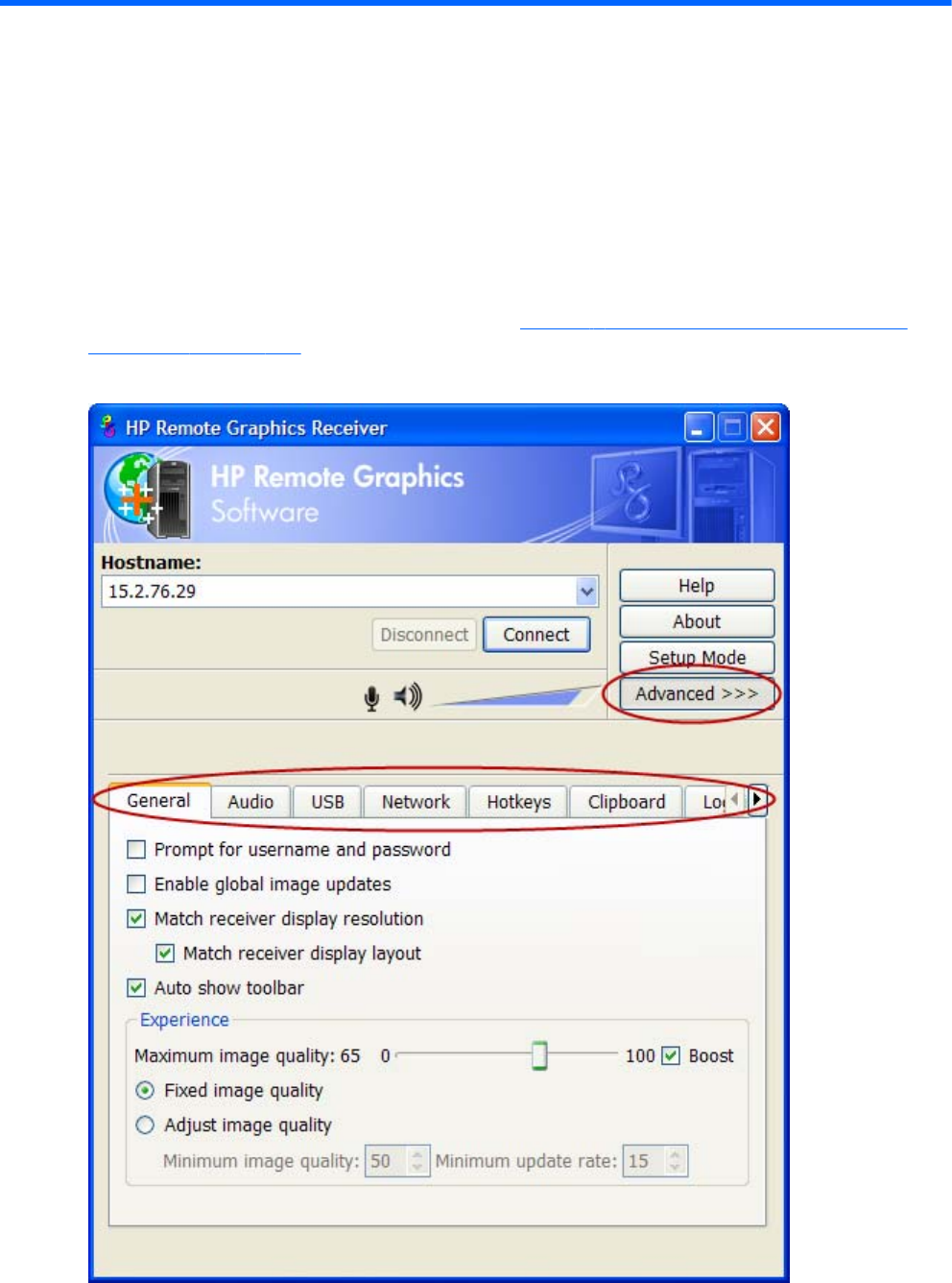
6 Advanced capabilities
This chapter discusses the many advanced capabilities of RGS. Click the Advanced>>> button in the
Receiver Control Panel to display the tabs shown in Figure 6-1 Tabs used to access advanced RGS
capabilities on page 118.
Figure 6-1 Tabs used to access advanced RGS capabilities
118 Chapter 6 Advanced capabilities
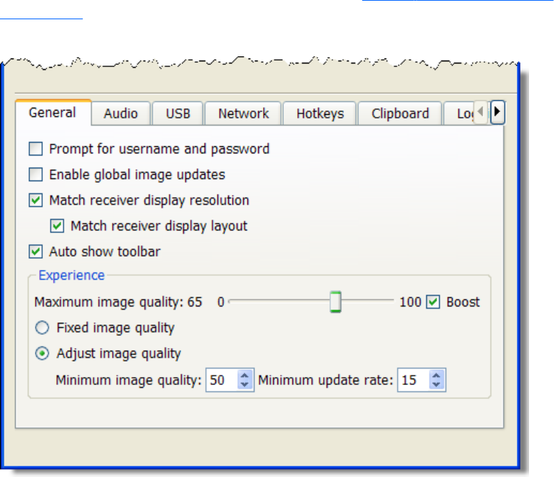
The capabilities available under each of these tabs will be described in detail. Unless required for
clarity, the portion of the Receiver Control Panel above the tabs will not be shown.
General options
General tab
The options available under the General tab are shown in Figure 6-2 General tab options
on page 119.
Figure 6-2 General tab options
General options 119
The options available under the General tab are:
●Prompt for username and password—In certain scenarios (such as silent authentication as
described in Standard Login on page 111) the Receiver will not prompt the local user for a
domain, username, and password. If the local user desires a prompt in order to enter an alternate
domain, username, and password, the user can check this box. If checked, the authentication
dialog is always displayed when the Connect button is clicked. This is advantageous on Sender/
Receiver pairs running Windows and Directory Mode with different connection needs for each
session.
●Enable global image updates—When checked (enabled), all of the individual regions of the
Remote Computer Sender frame buffer that have changed since the last update of the Remote
Display Window are combined into a single update that encloses all of the regions that have
changed. The advantage of this approach is that there is no perceptible painting of the individual
regions as can sometimes be observed when this option is disabled. However, the single rectangle
can include a large number of pixels that have not changed since the last update, and thus can
significantly reduce the update rate. Enabling this option may improve visual quality at the
expense of performance.
●Match receiver display resolution—When checked, the Receiver will negotiate with the
Remote Computer Sender to have the Sender adjust its display resolution to match the Receiver
display resolution. If the Sender is unable to match the resolution of the Receiver, a warning dialog
is issued to the local user.
NOTE: Match receiver display layout is not supported on Linux by default. Users need to
configure the X-Server with the proper modelines and or metamodes for this feature to work.
●Match receiver display layout—This checkbox is new with RGS 5.1.3. When checked, the
Receiver will try to set the layout of the Remote Computer's physical displays to have the same
display layout and resolution as the Receiver displays. If the Sender is unable to match the layout
and resolution of the Receiver physical displays, the Sender will try to just match the Receiver
display resolution. For example, if the Receiver has two physical displays in a 1x2 layout and a
overall virtual display resolution of 2560x1024 (1280x1024x2), the Receiver will try to set the
Sender to the same layout and resolution. If that fails, the Receiver will try to set a single Sender
physical display resolution of 2560x1024. If that fails, an error is reported to the local user.
NOTE: Match receiver display layout is not supported on Linux.
For information on the properties associated with the above two checkboxes, see Receiver general
properties on page 182—specifically, see the Rgreceiver.IsMatchReceiverResolutionEnabled and
Rgreceiver.IsMatchReceiverPhysicalDisplaysEnabled properties.
●Auto show toolbar—Automatically display the toolbar when the cursor is near the top of the
Remote Display Window.
General tab Experience section
Introduced in RGS 5.4.5, the controls available in the Experience section allow the user to adjust for
a better interactive experience. Typically these adjustments will be made when working with highly
interactive applications such as a CAD application in low bandwidth and/or high latency network
environments. Allowing RGS to degrade the image quality while attempting to maintain a minimum
update rate, can smooth the movement of objects on the screen during the movement of the object.
120 Chapter 6 Advanced capabilities
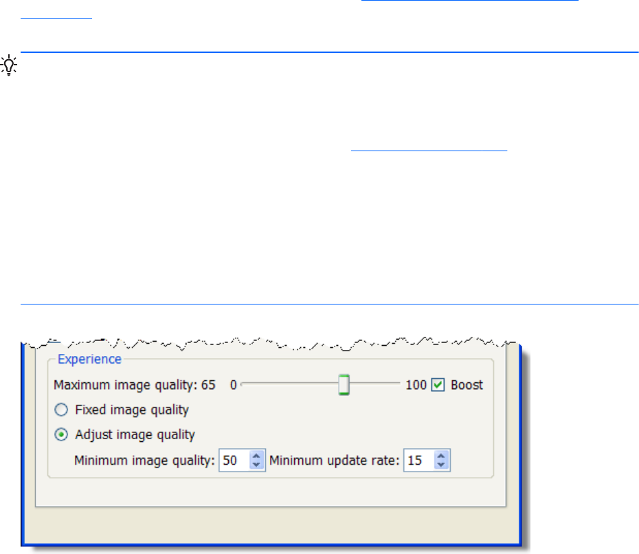
When the user stops interacting, RGS will return the image quality to the level set by the Maximum
image quality slider if the update rate will allow. These controls will also improve the viewing of
video by degrading the image quality to a point where the update rate can be maintained thereby
smoothing the video. Experimentation with both the Minimum image quality setting and the
Minimum update rate will allow the user to find an acceptable image quality while enjoying
smoother interactive movements on the screen. While the RGS 5.4.5 Receiver and Sender will
interoperate with previous RGS versions, as described in Sender and Receiver interoperability
on page 15 , both the RGS Receiver and Sender must be revision 5.4.5 or newer to use the new
interactive experience controls.
TIP: Certain Windows user environment configuration adjustments can improve the user interactive
experience by minimizing the bandwidth required.
Mute the audio on the Receiver if it is not needed using the Receiver's mute button, not the system mute
function, or adjust the audio in the Receiver Advanced > Audio tab to use mono with a the quality at
11 or 22 KHz. See an example of these controls in the Using audio on page 134 section.
Adjust the Performance settings using the Windows Control Panel > System Properties >
Advanced.
The Adjust for best performance option will minimize the bandwidth requirements for RGS. The
most noticeable performance improvement can be made by disabling the fade and animation options,
especially the Animate windows when minimizing and maximizing option. Text based
applications performance is most improved by disabling Smooth edges of screen fonts and
ensuring that the RGS Boost button is enabled (default).
Figure 6-3 General tab Experience section
General options 121
●Maximum image quality—This is the original user quality adjustment. The quality slider
adjusts the maximum image quality desired. When selecting Fixed image quality RGS will
maintain the image quality specified by this control setting. When selecting Adjust image
quality RGS will use this control setting for the target image quality when the updates per second
allow.
●Fixed image quality—RGS maintains the image quality specified by the Maximum image
quality slider described above. This selection is the default and will provide the best interactive
experience in high bandwidth and/or low latency network environments. Select this choice for the
normal RGS behavior as in previous versions.
●Adjust image quality—When selected, RGS will begin to degrade the image quality down to
the Minimum image quality setting anytime the updates per second falls below the
Minimum update rate. This selection is useful in low bandwidth and/or high latency network
environments. By adjusting these settings, a better interactive experience is achieved.
◦Minimum image quality—The Minimum image quality control specifies the lowest
quality level that will be used during the automatic adjustment. The Minimum image
quality is absolute - the system will not lower quality below the specified value. Valid
settings are from 0 to 100.
◦Minimum update rate—The Minimum update rate controls how aggressively the
image quality is reduced. Specifying a Minimum update rate of 30 will drive the most
aggressive quality reduction. The Minimum update rate is a target. The available
bandwidth may be too low to maintain the target rate. Valid settings are 0 to 30 updates per
second.
122 Chapter 6 Advanced capabilities

Auto Launch
On Windows beginning with RGS 5.4.0, the RGS Receiver supports file association. The user can
create property files with the extension ".rgreceiver" using the same format as the RGS Receiver
configuration file. See Setting property values in a configuration file on page 174 for more details. For
example, the file "hostname.rgreceiver" could be used for creating a property configuration file for
connecting to the system with name "hostname". If the user double-clicks or opens a file with the
".rgreceiver" extension, the RGS Receiver will be automatically started and the property file read and
applied. Create a folder in the user's home folder to safely store Auto Launch configuration files. See
Auto Launch session properties on page 196 for property details.
Auto Launch 123

Game Mode
Game Mode is a feature accessed via Hotkeys on page 156 introduced in RGS 5.4.0.
When operating in normal cursor mode, RGS synchronizes the cursor movements of a Sender to a
controlling Receiver by placing the senders cursor at the same absolute coordinates of the receivers
cursor. Some applications rely on a relative movement of the cursor to interact with a 3D environment.
These applications may programmatically readjust the cursor position after a movement is detected. In
the default mode of operation where RGS is moving the cursor to an absolute position, these
applications may have erratic behavior or cause a loss of cursor control. Game Mode is an attempt to
provide better cursor control for such applications.
Game Mode is a toggle on the Receiver to supply the Sender with relative cursor movements. This will
enable applications that rely on relative movements to be controlled with RGS. Game Mode is enabled
and disabled by pressing the hot key followed by the ‘G’ key. By default, the key sequence is ‘Shift
Down, Space Down, Space up, G’.
When Game Mode is enabled, the cursor will be locked to the Receiver's Remote Display Window.
The Remote Display Window Toolbar can be enabled, but interacting with the Remote Display Window
Toolbar is not possible when Game Mode is enabled. The Receiver is dependent on the Sender for
updating the cursor position. Network connections with a high latency may not be suitable for use with
Game Mode. The Remote Display Window can be repositioned without leaving Game Mode. When a
connection is terminated, Game Mode will be disabled.
RGS may not be suitable for full screen games. The techniques used by games to quickly draw to the
screen will often prevent RGS from being able to extract the contents of the remote frame buffer for
display. This is often seen as partially rendered scene or a completely scrambled scene. A game that
works in a windowed mode may be able to be controlled when Game Mode is enabled. However, the
extremely high frame rates and low latencies required to successfully operate some games are not
possible with the current RGS protocol. See Application support on page 16 for the official description
of supported applications.
Remote audio operation
For an overview of remote audio, see Remote audio on page 38. Before describing the RGS audio
capabilities available under the Receiver Control Panel Audio tab, Sender audio configuration and
calibration are described.
Configuring audio on the Windows XP Professional Sender
NOTE: It is critical that a mixer control such as “Wave Out Mix”, “Stereo Mix”, or some variation on
“Mixer” is available. The Creative Audigy driver calls this the “What U Hear” control. See Figure 6-8
Recording Control dialog on page 128 for a mixer example. If a mixer control is not available, see
Potential audio issues on page 135 for troubleshooting suggestions.
To configure audio on the Windows XP Professional Sender, open the Sound and Audio Devices
Properties dialog in the Windows Control Panel, and select the Audio tab (see Figure 6-4 Sound and
Audio Devices Properties dialog on page 125).
124 Chapter 6 Advanced capabilities
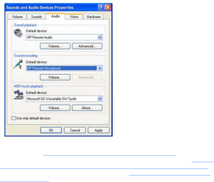
Figure 6-4 Sound and Audio Devices Properties dialog
The first step is to configure the Sound playback device (if used) and the Sound recording device (if
used). As shown in Figure 2-23 RGS audio subsystem on Windows on page 38, the Sender contains
audio components for both Sound playback and Sound Recording (microphone input). Figure 6-5
Microphone device selection and audio playback device selection on the Sender on page 126 on the
next page repeats the Sender portion of the diagram from Figure 2-23 RGS audio subsystem on
Windows on page 38, and describes how to select the Sound playback and Sound recording devices
on your Remote Computer.
Remote audio operation 125
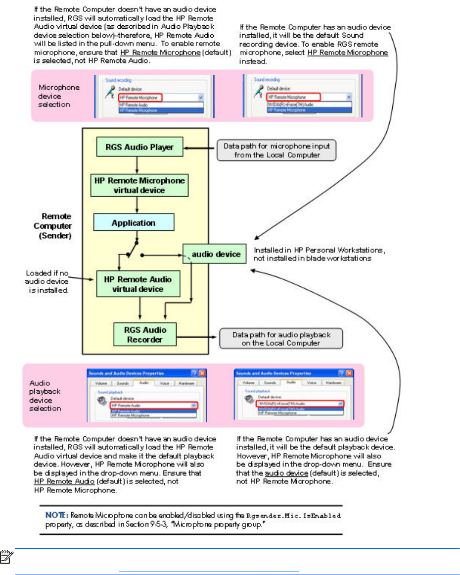
Figure 6-5 Microphone device selection and audio playback device selection on the Sender
NOTE: Remote Microphone can be enabled/disabled using the Rgsender.Mic.IsEnabled property, as
described in the section Microphone property group on page 203.
The HP Remote Audio device has only the mixer available in the recording control panel and the
volume level for this line cannot be adjusted. If an audio device is detected during installation, an
attempt is made to select the mixer as the recorder input. Due to wide variations in naming and volume
levels, it is likely that the mixer line will need to be selected by hand.
126 Chapter 6 Advanced capabilities
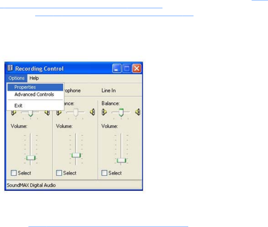
To select the mixer as the input line, click the Volume button in the Sound recording section of Figure
6-4 Sound and Audio Devices Properties dialog on page 125. This brings up the Recording Control
window (see Figure 6-6 Select Recording Control Properties on page 127). Many audio device drivers
do not show all available inputs by default. The mixer line is often one of the control lines that is not
visible by default. To make it visible, click the Options item in the menu, and then click Properties as
shown.
Figure 6-6 Select Recording Control Properties
This brings up another window showing all available volume controls. The control associated with the
mixer is often called “Wave Out Mix”, “Stereo Mix”, or some variation on “Mixer”. The Creative
Audigy driver calls this the “What U Hear” control. Make sure this control is enabled in a similar
manner to Figure 6-7 Recording Control Properties dialog on page 128.
Remote audio operation 127
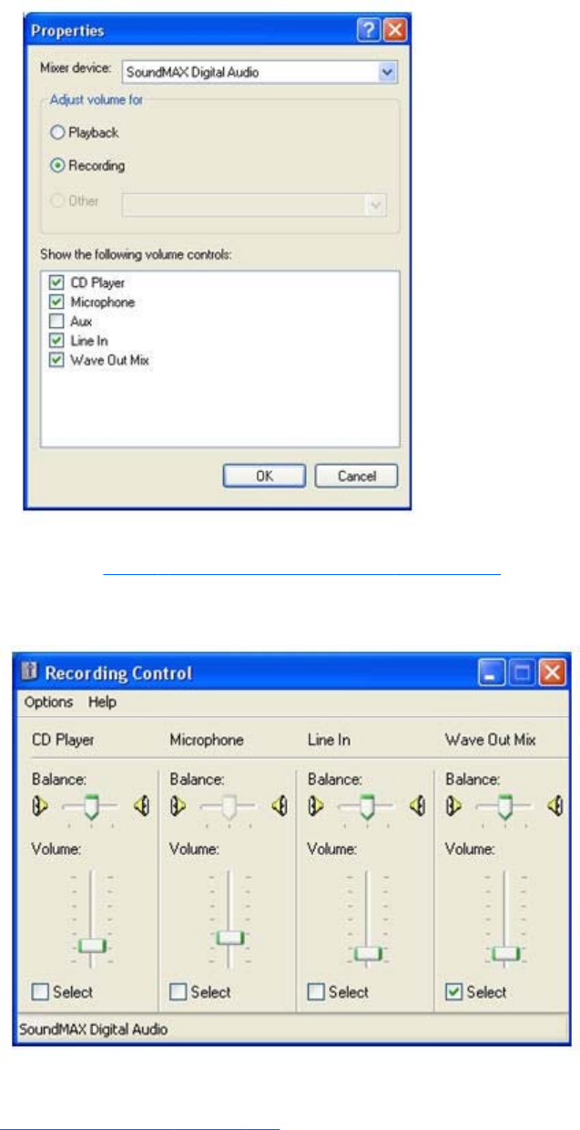
Figure 6-7 Recording Control Properties dialog
Press the OK button and the Recording Control window should now have the mixer line as one of the
controls (see Figure 6-8 Recording Control dialog on page 128). Make sure this item is selected, and
the volume level is not at the lowest setting.
Figure 6-8 Recording Control dialog
After selecting the mixer, the Sender should record audio information and send it to the Receiver. See
the following section to improve the audio quality. If you are not receiving an audio signal, refer to
Potential audio issues on page 135.
128 Chapter 6 Advanced capabilities
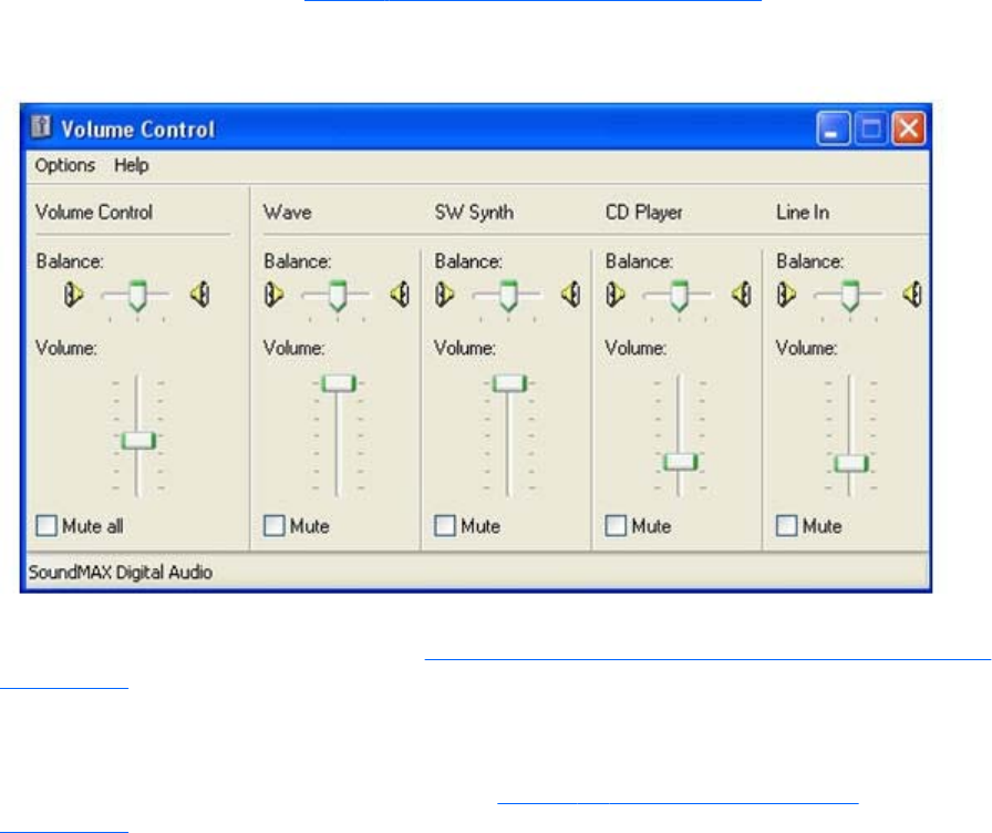
Calibrating audio on the Windows XP Professional Sender
The audio signal captured by the Sender is modified by two different device driver volume controls,
and then the master volume level is artificially inserted into the signal. If these volume controls are too
low, you might not hear the audio signal. If they are too high, the signal might be distorted. This section
describes a technique to hand tune the volume controls to reduce the amount of distortion. These
operations should be performed while connected to the Sender through the Receiver.
The Wave line of the volume control is the first volume control to affect the audio signal outside of the
application that generates the signal. Setting this value to the maximum level gives you the most
resolution in your audio signal. Figure 6-9 Volume Control dialog on page 129 shows the Wave
volume control at its maximum level.
Figure 6-9 Volume Control dialog
The next volume control to adjust is the mixer line in the Recording Control window. The name of this
line varies with different audio devices. See Configuring audio on the Windows XP Professional Sender
on page 124 for information on how to determine the name of this control. For our example, the
control is called Wave Out Mix. Adjust this volume control while playing a sound. At higher levels, the
audio signal gets clamped and the signal becomes distorted. Decrease the level until the sound
becomes clear. On some devices, the mixer volume control does not go to zero. In this case, the Wave
line of the Volume Control will need to be reduced. Figure 6-10 Recording Control dialog
on page 130 demonstrates the Wave Out Mix level needed to eliminate distortion.
Remote audio operation 129
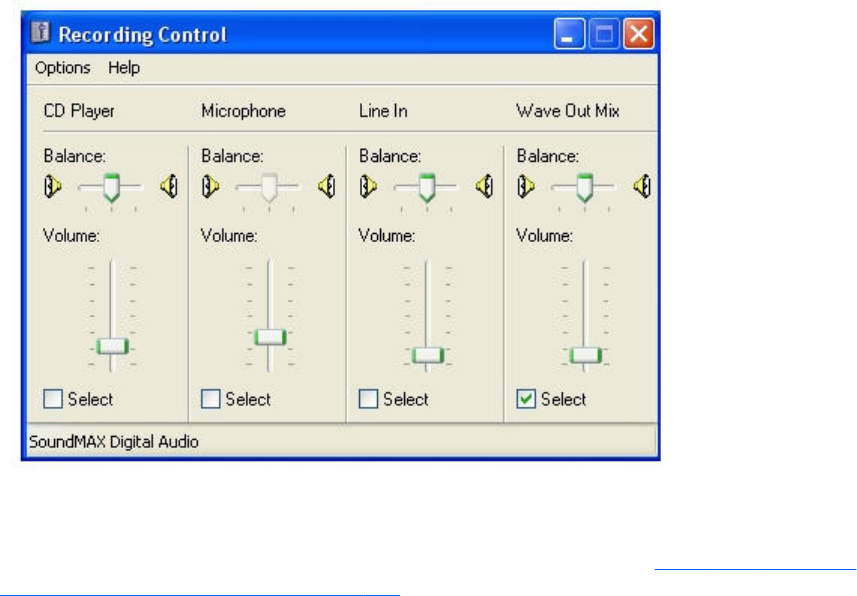
Figure 6-10 Recording Control dialog
The best sound to play to calibrate your audio device is a low frequency sound with high amplitude. By
default, Windows has a program event that meets these requirements. To play this sound, open up the
Sound and Audio Devices window, and click the Sounds tab as shown in Figure 6-11 Sound and
Audio Devices Properties dialog on page 131.
130 Chapter 6 Advanced capabilities
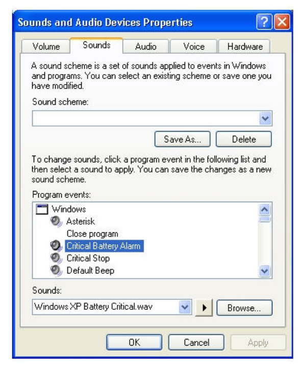
Figure 6-11 Sound and Audio Devices Properties dialog
Select the Critical Battery Alarm program event, and press the play button (the triangle located next to
the Browse button). The wav file associated with this event is recorded near maximum intensity. If you
can play this sound without distortion, most sounds should play without distortion. Some media
applications modify their audio signal prior to sending it to the audio device. The Windows Media
Player may appear to distort some audio files. This is due to signal modification by some type of
enhancement, such as an equalizer.
Remote audio operation 131
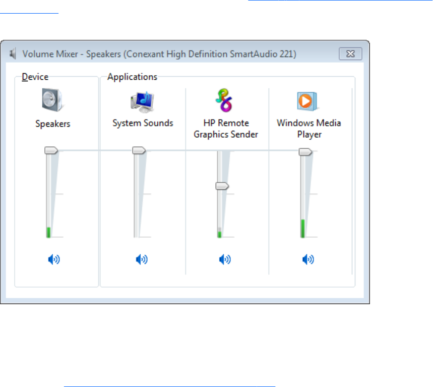
Configuring audio on Windows 7 Sender
When a connection is established between a Receiver and Sender, an audio session is created on the
Sender. When audio is enabled in the Receiver GUI, audio will be captured from the default playback
device. The master volume level on the Sender should have the expected impact on the remote audio
volume level. Windows 7 also allows application specific volume controls through the Volume Mixer.
This can be opened through the volume control in the taskbar. This control will allow the Sender volume
to be adjusted relative to the master volume as shown in Figure 6-12 Volume Mixer for Windows 7
on page 132
Figure 6-12 Volume Mixer for Windows 7
Configuring audio on Linux
The audio devices on Linux are not consistent in the naming conventions of the audio controls. The RGS
Sender installer will attempt to adjust volume levels for known audio devices to allow audio to be
captured. See Linux remote audio device support on page 235 for a list of supported audio devices.
This section describes how to adjust volume levels for the supported audio devices. This information
may be helpful for configuring audio devices that are not currently supported by the RGS Sender
installer.
Volume levels can typically be adjusted through the Volume Control application. This is usually found in
the gnome panel or the system preferences menu. The Volume Control application may not show all
available volume controls. The preferences for the Volume Control application may need to be adjusted
to allow access to hidden volume controls.
The alsamixer is a command line program for adjusting volume. This application will not hide audio
controls like its GUI counterpart, however it is not as intuitive. Press the h key after running alsamixer to
get additional information on how to control capture volumes.
132 Chapter 6 Advanced capabilities
The Audigy2ZS and Audigy 4 audio devices require the controls labeled "PCM Capture" to have a
non-zero volume. Other volume controls will not impact the volume of the signal captured through RGS.
Since the Master control does not impact RGS, the volume of the speakers on the sender system can be
muted without preventing RGS from capturing an audio signal.
The Sound Blaster Live! needs to have recording enabled on the Wave control in addition to having a
non-zero volume level. Similar to the Audigy cards, the Master control does not impact RGS.
Unsupported PCI audio devices are known to allow capture of application generated audio. The names
of the controls that need to be adjusted are not consistent. Names of controls that may need to be
adjusted include "PCM", "Capture" and "Mix".
Disabling audio on the Sender
Most audio devices will allow the Sender speakers (if present) to be disabled while still allowing audio
to be sent to the Receiver. This is done by enabling the mute for the master volume control through the
Sounds and Audio Devices control panel or through the Volume icon in the taskbar. The Volume icon in
the taskbar will change when mute is enabled.
Enabling mute on some devices will prevent audio from arriving at the Receiver. The Realtek audio
device used in the HP xw4300 has this issue. One possible solution when running the 32-bit version of
Windows is to disable the audio device prior to installing the Sender. This will cause the HP Remote
Audio device driver to be installed. The real audio device and the HP Remote Audio device should not
be enabled at the same time. The Sender will connect to the first audio device it detects, which may not
be the device that is selected by the user.
Remote audio operation 133
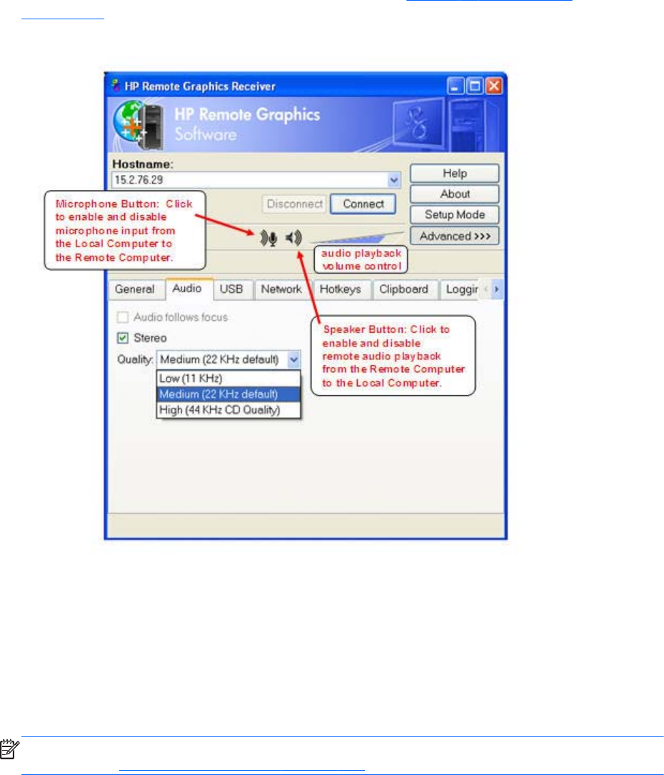
Using audio
The audio controls in the Receiver Control Panel are shown in Figure 6-13 Audio controls
on page 134.
Figure 6-13 Audio controls
The Speaker Button on the Receiver Control Panel enables and disables remote audio playback. When
remote audio playback is enabled, the Sender records and transmits audio to the Receiver for
playback. Audio controls in the Receiver Control Panel allow you set the audio volume, quality, and
stereo/mono format. Note that audio quality and stereo settings will affect your overall network usage
—higher quality audio and stereo usage will increase the network traffic.
The Microphone Button on the Receiver Control Panel enables and disables remote microphone. When
remote microphone is enabled, microphone input from the Local Computer is sent to the Remote
Computer for capture by the Remote Computer application.
NOTE: The audio controls in the Receiver Control Panel can be set by using Receiver audio
properties. See Receiver audio properties on page 190.
134 Chapter 6 Advanced capabilities

The options available under the Audio tab are:
●Audio follows focus—This checkbox determines how audio is handled when the Receiver is
connected to multiple Remote Computers in Directory mode. Checking this box enables playback
of the audio stream from the Remote Computer whose Remote Display Window currently has the
keyboard focus. When unchecked, the Receiver combines the audio from all Remote Computers
into a single audio stream. If multiple Receivers are executing, the audio is combined from all
Receivers into a single audio stream.
NOTE: Directory Mode operation is discussed in Using Directory Mode on page 170.
●Stereo—This checkbox enables or disables stereo audio. Stereo audio sends independent audio
streams for the left and right channels but at the expense of greater network bandwidth utilization.
If this box is unchecked, monaural audio is sent by the Remote Computer.
●Quality—This pull-down menu allows the local user to select one of three different audio quality
settings:
◦Low—Specifies a sampling rate of 11 kHz.
◦Medium—Specifies a sampling rate of 22 kHz.
◦High—Specifies a sampling rate of 44 kHz, which is equivalent to CD quality audio.
Higher quality audio (and its higher sampling rate) requires more network bandwidth, and
can impact the performance of RGS, especially over bandwidth-constrained networks.
Potential audio issues
Several potential audio issues are described below along with their potential causes.
●No mixer control available on Windows XP — If a mixer control such as “Wave Out Mix”,
“Stereo Mix”, “What U Hear”, or an equivalent control is not available, remote audio will not
work. Either disable the audio device and reinstall the RGS Sender to get the virtual audio driver,
update the audio driver, or use a different audio device.
●No audio on Windows Receiver—Verify that your Local Computer audio device is working. The
volume control slider on the Receiver should play the default beep when released. Ensure that the
Speaker Button on the Receiver Control Panel is not in the mute position. Refer to Configuring
audio on the Windows XP Professional Sender on page 124 for information on selecting the mixer
as the input line. Refer to Calibrating audio on the Windows XP Professional Sender on page 129
for information on how to ensure the volume levels are not too low. Make sure that mute is not
enabled on the Wave line of the Sender or Receiver Volume Control.
●No audio on Windows 7 after connecting or disconnecting an audio device—Reconfiguring an
audio device while an application is using that device can cause the application to stop working.
If an audio device is reconfigured, the Sender may stop transmitting audio. Disconnecting the
Receiver and reconnecting will cause the Sender to use the new audio configuration.
Some audio device drivers have the ability to detect when a speaker jack is in use. Plugging in
headphones to these devices may cause the device to reconfigure. This can result in temporary
loss of remote audio. Reconnecting the Receiver may be necessary to restore audio.
Remote audio operation 135

If all of the audio devices on a system are configured as not plugged in, the audio device cannot
be opened. Some programs, such as Windows Media Player, will display an error indicating that
an audio device is not available. Something will need to be plugged into one of the unplugged
devices to allow audio to work on these devices.
●Audio not continuous—Low bandwidth connections can cause discontinuities in the audio stream.
Reducing the quality and turning off stereo may improve the audio quality. Some high priority CPU
intensive tasks may disrupt the audio stream. The Windows Task Manager may help you identify
such a task. Another possible problem may be a bad network setup.
●PC speaker sounds not working—The Sender captures all audio information sent through the
mixer. This includes most audio alerts, MIDI, Direct Sound and Direct Music. Sounds generated by
the PC speaker are not captured by the Sender and will not be transmitted.
●Audible pops and glitches in sound—This is most likely because the network bandwidth or system
resources are starving the audio streaming from continuous play.
◦Try a lower audio quality setting to reduce network bandwidth usage.
◦Be sure you system is not doing something so computationally intensive that it is starving RGS
from keeping up with graphics and audio processing.
●Enabling audio causes continuous network traffic—When the Sender detects an audio signal, that
signal is sent to the Receiver. If the audio device on the Sender is silent, there should not be any
network traffic due to audio. If the audio device is generating a large amount of noise, that noise
may be interpreted as an audio signal, and be sent to the Receiver. This may occur when
something is connected to the "Line In" port of the audio device. Reducing volume levels or
disconnecting any external devices may help reduce the interference.
●ToggleKeys sound not working—The Accessibility control in Windows will play a sound when
some control keys are pressed. This sound is not heard on the Receiver because it is played
through the PC Speaker. See the section “PC speaker sounds not working” above.
●No audio with multiple audio devices—The Sender will open up the device that is registered as
the default audio device. The Sender is a service that is running in a different context. If you have
multiple audio devices, it may choose a different device than you have selected as the default.
Disable the extra audio device to ensure the Sender uses the correct device. See Configuring
audio on the Windows XP Professional Sender on page 124 to set up the audio device after
disabling the extra audio device.
Remote USB operation
For an overview of remote USB, see Remote USB overview on page 30.
This section provides an example of using remote USB. A USB drive key is plugged into the Local
Computer, and remote USB is used to attach the drive key to a Remote Computer. This example
assumes the Receiver was installed with the remote USB configuration option shown in Figure 6-14 USB
configuration during Receiver installation —USB devices are Local or Remote on page 137. For a
discussion of the USB installation options, see Installing the Receiver on Windows on page 53.
136 Chapter 6 Advanced capabilities
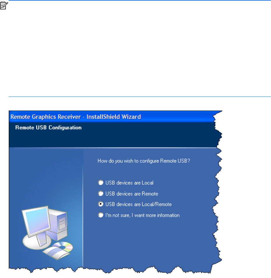
NOTE: Hewlett-Packard RGS supports remote USB. Devices that adhere to the USB standard should
work. Because RGS is a remote graphics protocol and is emulating the USB protocol over a network,
devices that are sensitive to timing may not work at all. This includes USB devices with security and
encryption mechanisms built into them. The additional network delay could be looked at as a threat.
Other devices that are known to break the USB standard, such as WEB CAMS, may also not function
at all. Performance of USB devices over RGS will not be equal to that of a locally connected device.
File copies may take longer due to the additional overhead of the network protocol sitting on top of the
USB protocol.
HP recommends that customers thoroughly test any USB device they are considering to use with RGS as
Hewlett-Packard cannot certify and or guarantee it will work over a remote USB protocol. Many USB
vendors do not support their devices over any remote USB protocol and you should check with the USB
vendor for support concerns first.
Figure 6-14 USB configuration during Receiver installation —USB devices are Local or Remote
Remote USB operation 137
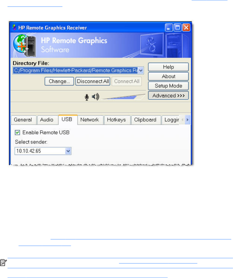
Attaching a local USB device to a Remote Computer
The options available under the USB tab in the Receiver Control Panel are shown in Figure 6-15 USB
tab options on page 138.
Figure 6-15 USB tab options
The USB options are:
●Enable Remote USB—This checkbox can be used to dynamically (during an active RGS
connection) enable or disable USB connections to the Remote Computer. When enabled, USB
devices plugged into the Local Computer appear to the Remote Computer as locally attached
devices. Because remote USB supports hot plug connections, it is not necessary to disable remote
USB before plugging or unplugging USB devices on the Local Computer.
●Select sender—If multiple Remote Computers are specified in Directory Mode, the Select sender
drop down menu is used to select which Remote Computer (Sender) receives the remote USB
connection. In Figure 6-14 USB configuration during Receiver installation —USB devices are Local
or Remote on page 137, the RGS Receiver is operating in Directory Mode and the Remote
Computer at IP address 10.10.42.65 is selected to receive the remote USB connection.
NOTE: Directory Mode operation is discussed in Using Directory Mode on page 170.
Figure 6-16 Prior to remote attachment of the USB drive key on page 139 shows the presence of the
USB drive key on the Local Computer before the remote USB attachment is made.
138 Chapter 6 Advanced capabilities
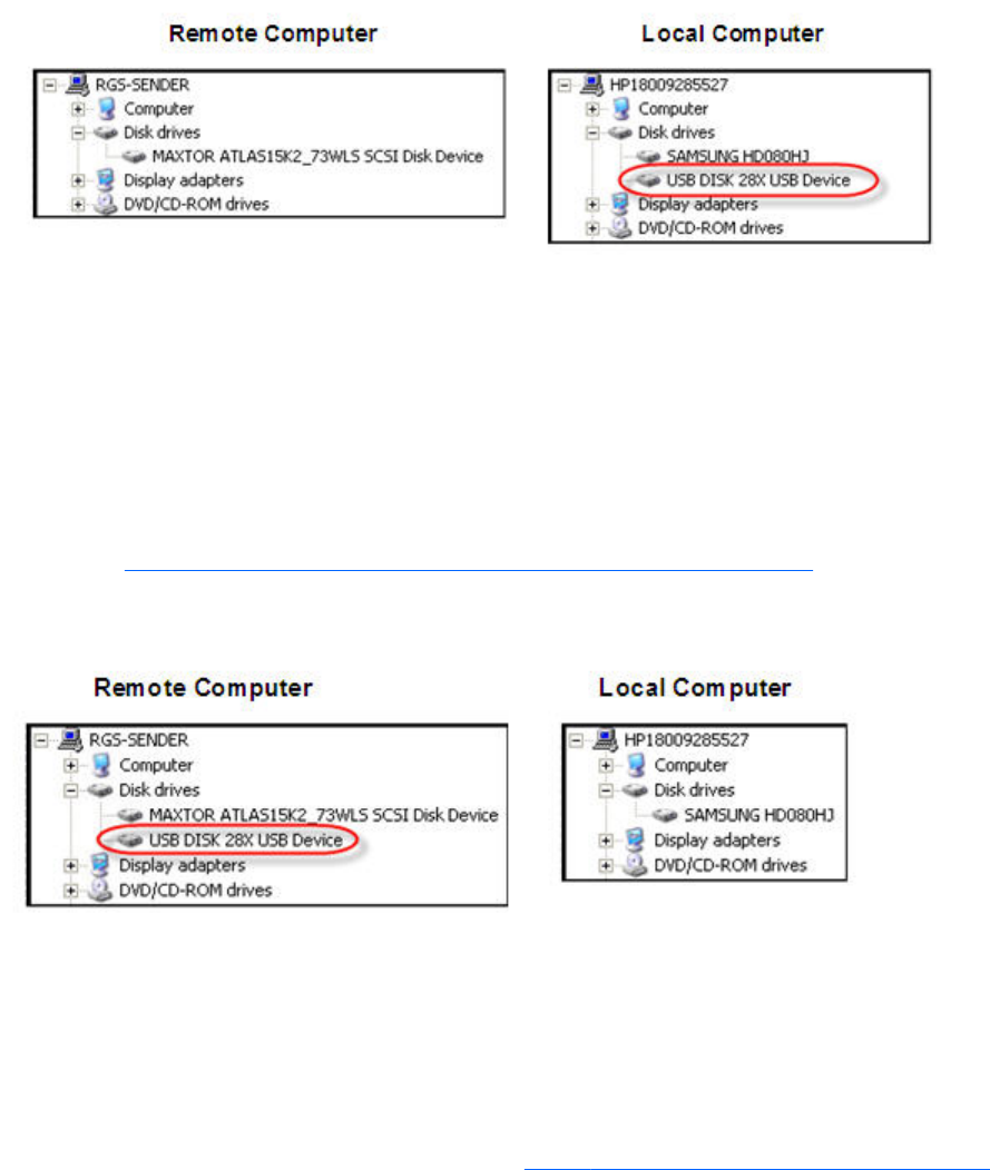
Figure 6-16 Prior to remote attachment of the USB drive key
To connect the USB drive key to a Remote Computer in Directory Mode, perform the following steps:
1. Click the USB tab on the Receiver Control Panel.
2. Click the Enable Remote USB checkbox to enable the remote USB connection.
3. Select the IP address (or hostname) of the Remote Computer, and click Connect.
4. Once connection has been established, remove and re-insert the USB drive key—this step is
required to initiate the remote USB attachment.
As shown in Figure 6-17 After remote attachment of the USB drive key on page 139, the USB drive
key is now attached to the Remote Computer, and is no longer available to the Local Computer.
Figure 6-17 After remote attachment of the USB drive key
USB session switching
New with RGS 5.1.3 is the ability to dynamically move USB devices from one Remote Computer to
another. This enables USB devices to be detached from one Remote Computer, and made accessible
by another Remote Computer without first needing to disconnect the RGS connections. To move USB
devices to a different Remote Computer in Directory Mode, simply specify the new Remote Computer
(Sender) in the Select sender: dropdown menu (see Figure 6-18 Dynamically moving USB devices to
Remote USB operation 139
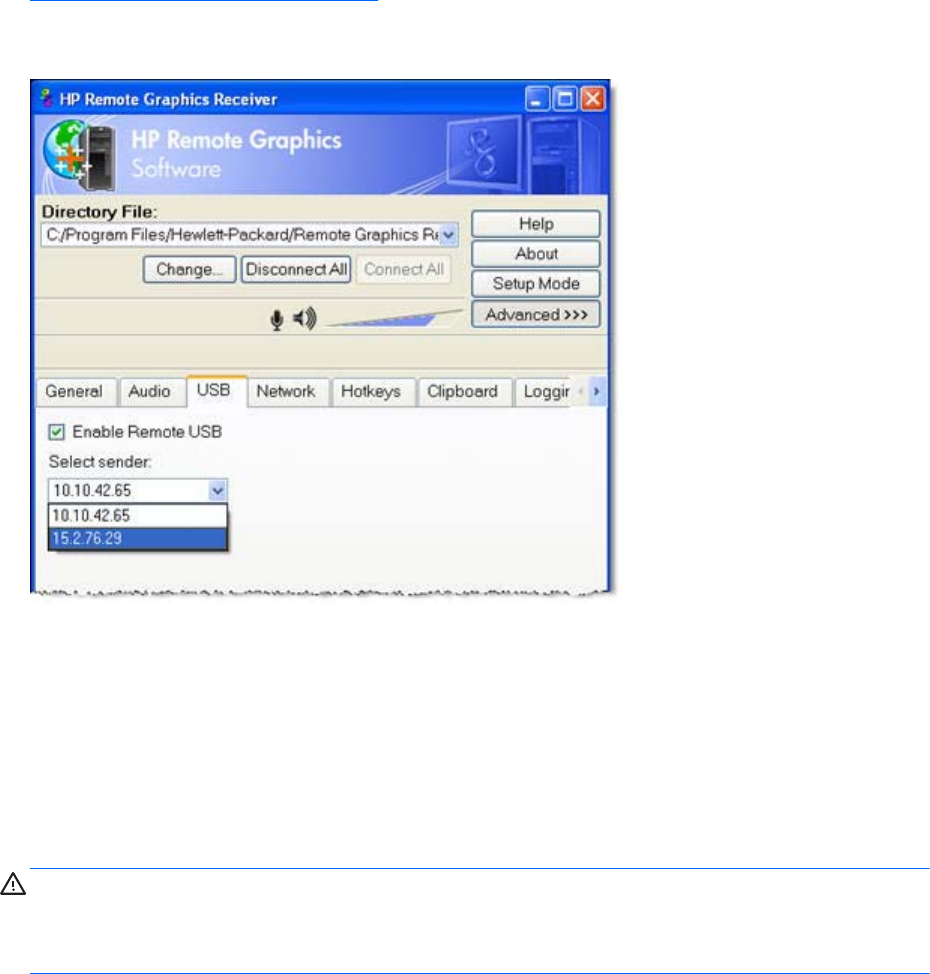
another Remote Computer on page 140). The USB devices will be detached from the current computer
and attached to the selected computer.
Figure 6-18 Dynamically moving USB devices to another Remote Computer
Local/Remote USB Device Management
In addition to the general default settings for remote USB configurations, RGS 5.2.6 and higher
releases support auto-remote and auto-return of user-specified USB devices when using Windows on
both the Sender and Receiver platforms. RGS 5.4.0 introduced a new auto-remote configuration syntax
for the Windows Registry entries. Auto-remote allows specified USB devices to be automatically
attached to a remote Sender session at RGS connection and then returned to the local client at RGS
disconnect.
CAUTION: Enabling auto-remoting of specific USB devices requires modifications to the Windows
Registry. Registry modifications should only be made by experienced personnel. Because an incorrect
Registry setting can cause serious problems, you should always make a backup of the Registry prior to
making any changes.
To specify auto-remoting of a particular USB device, perform the following steps:
1. Get the vendor id and device id for your usb device using the following steps. For this example
assume that you found the vendor id is 0x1234 and device id is 0x5678.
a. Open Device Manager and find the USB device to be auto-remoted.
b. Right-click the USB device and select Properties.
c. Select the Details tab and select Hardware Ids in the dropdown menu. The Hardware Ids
format will be:
USB\Vid_xxxx&Pid yyyy
140 Chapter 6 Advanced capabilities
where xxxx is the VendorID and yyyy is the ProductID
The VendorID and ProductID are reported in hexadecimal format, and should be entered in
hexadecimal format in the new key created below.
2. Create the following Registry key:
HKLM\System\CurrentControlSet\Services\hprpusbh\Parameters\Device
3. Create the following Registry key, where the new key at the end of the Device key is the vendor
and device IDs like Vid_1234&Pid_5678:
HKLM\System\CurrentControlSet\Services\hprpusbh\Parameters\Device\Vid_1234&Pid_5678
4. In the key created in Step 3, create a string value (REG_SZ) named "Mode" :
HKLM\System\CurrentControlSet\Services\hprpusbh\Parameters\Device
\Vid_1234&Pid_5678\Mode
5. Set the Mode Data value to one of the following :
default – Allow the device to work in local, then remote mode.
local – Allow the device to be used on the local system only.
remote – Allow the device to be used on a remote system only.
auto – Allow the device to be used on the local system until there is a connection to a Sender
system. Once the connection has been made the device will be removed from the local system and
remoted to the Sender system.
Supported remote USB devices
HP has tested a number of USB devices to verify they work correctly when attached to a Remote
Computer from a Local Computer.
Remote USB Access Control List
RGS supports a per-Remote Computer access control list (ACL) file that specifies which USB devices are
allowed to be remotely attached to the Remote Computer from a Local Computer, and which USB
devices are denied attachment. The ACL file, which resides on the Remote Computer, supports
allowing/denying USB device attachments based on the following nine USB descriptor fields:
1. Device Class
2. Device Subclass
3. Device Protocol
4. Vendor ID
5. Product ID
6. Device BCD
7. Manufacturer
Remote USB operation 141

8. Product Type
9. Serial Number
USB device mounting can also be allowed/denied based on the following two parameters:
1. IP address of the Local Computer
2. The domain group of the local user
The ACL file supports two rule types: “allow” and “deny”. The rules are evaluated by the Remote
Computer for each USB connection request from a Local Computer as follows:
●If any rule indicates the USB connection should be denied, the connection is denied, regardless of
any other rule.
●If any rule indicates the USB connection should be allowed, and if there are no rules that deny the
connection, the connection is allowed.
●If no rules match at all, the connection is denied.
Therefore, a deny rule takes precedence over an allow rule. The ACL file is implemented as an XML
(Extensible Markup Language) file. The ACL schema file is located at:
C:\Program Files\Hewlett-Packard\Remote Graphics Sender\hprUsbAcl.xsd
For backwards compatibility, the following default ACL file(installed during Sender installation) allows
all USB connections to be made:
C:\Program Files\Hewlett-Packard\Remote Graphics Sender
\hprDefaultUsbAcl.xml
The names for these files can be changed using the properties described in Sender USB access control
list properties on page 203. The default ACL file contains the following contents, which allows all USB
connections to be made:
<?xml version="1.0" encoding="ISO-8859-1" standalone="no"?> <hprUsbAcl>
rule type="allow"> <name>Allow all USB devices (HP default)</name> </
rule> </ruleset> </hprUsbAcl>
The following example ACL file denies all remote USB attachment requests:
<hprUsbAcl> <ruleset> <rule type="deny"/> </ruleset> </hprUsbAcl>
Rules may contain filters based on the 11 parameters listed previously. These parameters are repeated
below along with the name of the filter element.
1. Device Class— bDeviceClass
2. Device Subclass— bDeviceSubclass
3. Device Protocol— bDeviceProtocol
4. Vendor ID— idVendor
5. Product ID— idProduct
142 Chapter 6 Advanced capabilities

6. Device BCD— bcdDevice
7. Manufacturer— manufacturer
8. Product Type— product
9. Serial Number— serialNumber
CAUTION: Filtering on device strings (manufacturer, product, and serial number) may not be
reliable. Device vendors are not required to add data to these fields, and many do not. Before
deploying a solution that depends on a string-based filter, ensure that the devices you wish to use
implement the appropriate device strings.
10. IP address of the Local Computer—peerAddress
11. The domain group of the local user—group
The following ACL file allows only USB devices with a Device Class (bDeviceClass) of 7 to be remotely
attached while denying everything else:
<hprUsbAcl> <ruleset> <rule type="allow"> <name>Allow printing devices</
name> <filter bDeviceClass="07"/> </rule> </ruleset> </hprUsbAcl>
The following ACL file denies USB devices for a specific range of Local Computer IP addresses while
allowing all other Local Computers to use remote USB:
<hprUsbAcl> <ruleset> <rule type="allow"> <name>Allow all devices</name>
</rule> <rule type="deny"> <name>Deny 192.168.9.0 subnet</name> <filter
peerAddress="192.168.9.0/20"/> </rule> </ruleset> </hprUsbAcl>
The following ACL file allows USB connections for members of the DEFAULT-DOMAIN\administrators
group while denying all other USB connections:
<hprUsbAcl> <ruleset> <rule type="allow"> <name>Allow members of DEFAULT-
DOMAIN\administrators</name> <filter group="DEFAULT-DOMAIN
\administrators"/> </rule> </ruleset> </hprUsbAcl>
Determining USB device information
This section describes how to obtain several of the most-used USB device parameters.
Determining USB device information for Windows
To obtain the Vendor ID and the Product ID for a USB device on Windows, perform the following steps:
1. Open the device manager.
●Go to the Control Panel and run "System"
●Select the "Hardware" tab
●Select the "Device Manager" button, this runs the device manager program.
2. Double-click the Universal Serial Bus Controllers
Remote USB operation 143

3. Double-click the specific device, which brings up a separate window.
4. Select the Details tab and select one of the following properties from the pull down menu:
●"Hardware Ids" property—This property shows the Vendor ID, Product ID and Revision for
the device. The Vendor ID is the 4 hex digits after "Vid_". The Product ID is the 4 hex digits
after "Pid_". The Revision is the 4 hex digits after "Rev_". For example, an iPod has a
"Hardware Ids" property that looks like this:
USB\Vid_05ac&Pid_120a&Rev_0001
This gives us the following values:
iPod Vendor ID: 0x05AC
iPod Product ID: 0x120A
iPod Revision: 0x0001
●"Compatible Ids" property—This property shows the class code, subclass code and protocol
code for the device. The class code is the 2 hex digits after "Class_". The subclass code is
the 2 hex digits after the "SubClass_". The protocol code is the 2 hex digits after the "Prot_".
For example, an iPod has a "Compatible Ids" property that looks like this:
USB\Class_08&SubClass_06&Prot_50
This gives us the following values:
iPod Class Code:08(Mass Storage Device)
iPod Subclass Code:06(SCSI transparent command set)
iPod Protocol Code:50(Bulk-only transport)
Determining USB device information for Linux
An open source program called "usbview" is available on the SourceForge web site. There are three
different programs called "usbview". The one to use is the "original" version. This is the plain usbview
that was registered on "1999-12-20" and is administered by "kroah". Do not use "usbview2" or
"usbview-1.8". The URL for this software is:
http://sourceforge.net/projects/usbview
Verifying the USB data
Once a device has been identified using one of the previous methods, you should verify that the correct
device was used. This can be done by consulting one of the many USB ID lists. There are documents
that contain most of the registered Vendor IDs and Device IDs. There are different documents that
contain the different registered classes and subclasses. By comparing the values of the device to these
documents, the user can verify that they are looking at the correct device and not some other device
that is also plugged into the system.
The linux-usb group keeps an up-to-date list of registered USB Vendor IDs and Device IDs. This
document resides on the http://www.linux-usb.org site at:
144 Chapter 6 Advanced capabilities
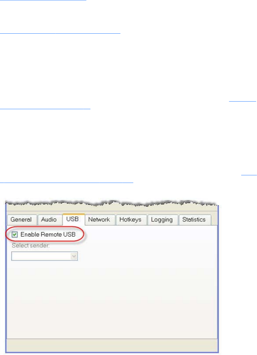
http://www.linux-usb.org/usb.ids
The registered classes and subclasses are documented by the USB Device Working Group (DWG). The
latest document from DWG for 1.0 defined class codes is hosted at:
http://www.usb.org/developers/defined_class
Troubleshooting remote USB
If you have problems connecting a remote USB device from a Local Computer to a Remote Computer,
the following checklist may help identify the problem.
Computers supporting remote USB
Ensure that both the Remote Computer and the Local Computer support remote USB— see Computers
supporting remote USB on page 36.
Supported USB devices
Verify that the USB device you’re using is supported. HP has tested a number of USB devices to verify
they work correctly when attached to a Remote Computer from a Local Computer.
Enable Remote USB
Verify that Remote USB is enabled under the USB option tab of the Receiver Control Panel (see Figure
6-19 Checkbox to enable Remote USB on page 145).
Figure 6-19 Checkbox to enable Remote USB
Remote USB operation 145
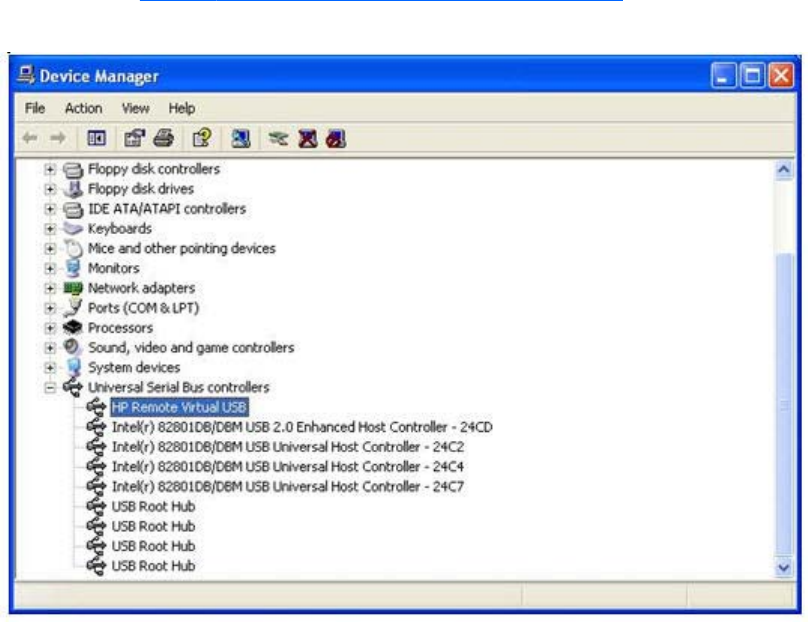
Check USB cable connections
Verify that the USB device is physically connected to the Local Computer. Check to see that it has
power and is turned on. Some devices may require that the user initiate an action before it connects.
To further verify your connections, recognized devices on the Receiver system appear in the Proc file
system under the /proc/devices/usb_remote directory. At least two files appear in this directory for a
single connected device:
●/proc/devices/usb_remote/devices — File contains a list of recognized devices by the Receiver
system.
●/proc/devices/usb_remote/# — If only one USB device is recognized, the "devices" file will have
a single entry, 192. The file descriptor named 192 is the Remote USB device. Dumping this file
with 'cat 192', for example, displays specific data about device 192. This should reflect the
connected USB device. If multiple devices are connected, then each will have a file descriptor
numbered consecutively starting at 192.
Reset the USB device
If the USB device has a reset button, press the button.
HP Remote Virtual USB Driver
Verify that the HP Remote Virtual USB driver is installed and active on the Remote Computer. Open the
Windows Device Manager, and verify that HP Remote Virtual USB is listed under Universal Serial Bus
Controllers (see Figure 6-20 HP Remote Virtual USB driver on page 146).
Figure 6-20 HP Remote Virtual USB driver
146 Chapter 6 Advanced capabilities
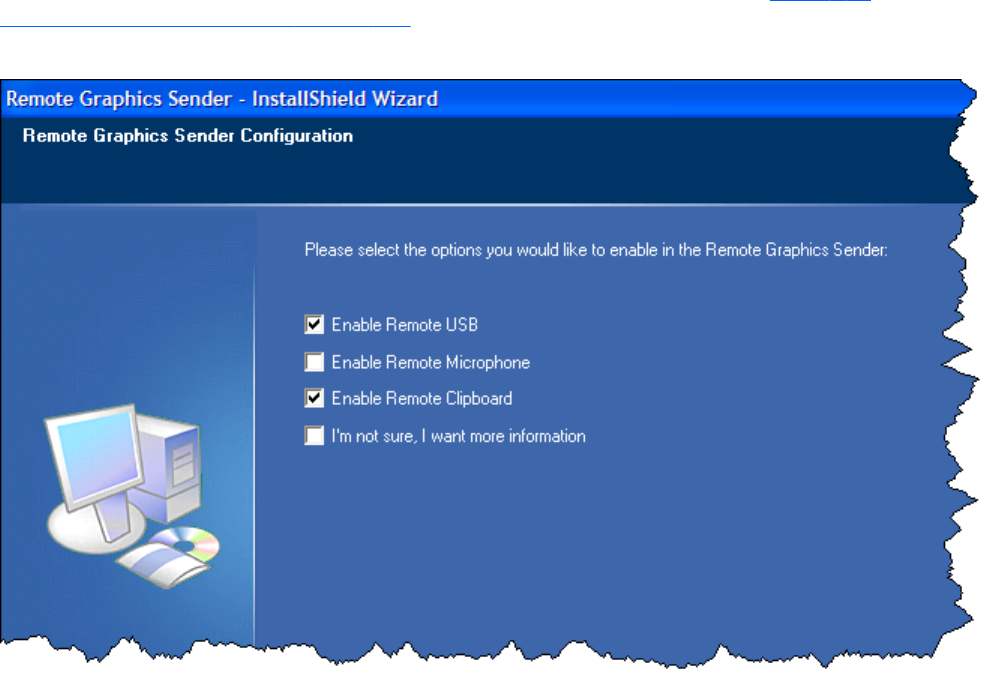
If the HP Remote Virtual USB driver is not reported, reinstall the RGS Sender software. During
installation, verify that the Remote USB box is checked in the Configuration window (see Figure 6-21
Enable installation of remote USB on page 147).
Figure 6-21 Enable installation of remote USB
USB device drivers and program support
Verify that the device drivers and programs required by the device are installed and available on the
Sender system. Many USB devices require manufacturer-supplied software to work on a system. This
software must often be installed before the USB device is connected to the system.
Remote USB operation 147
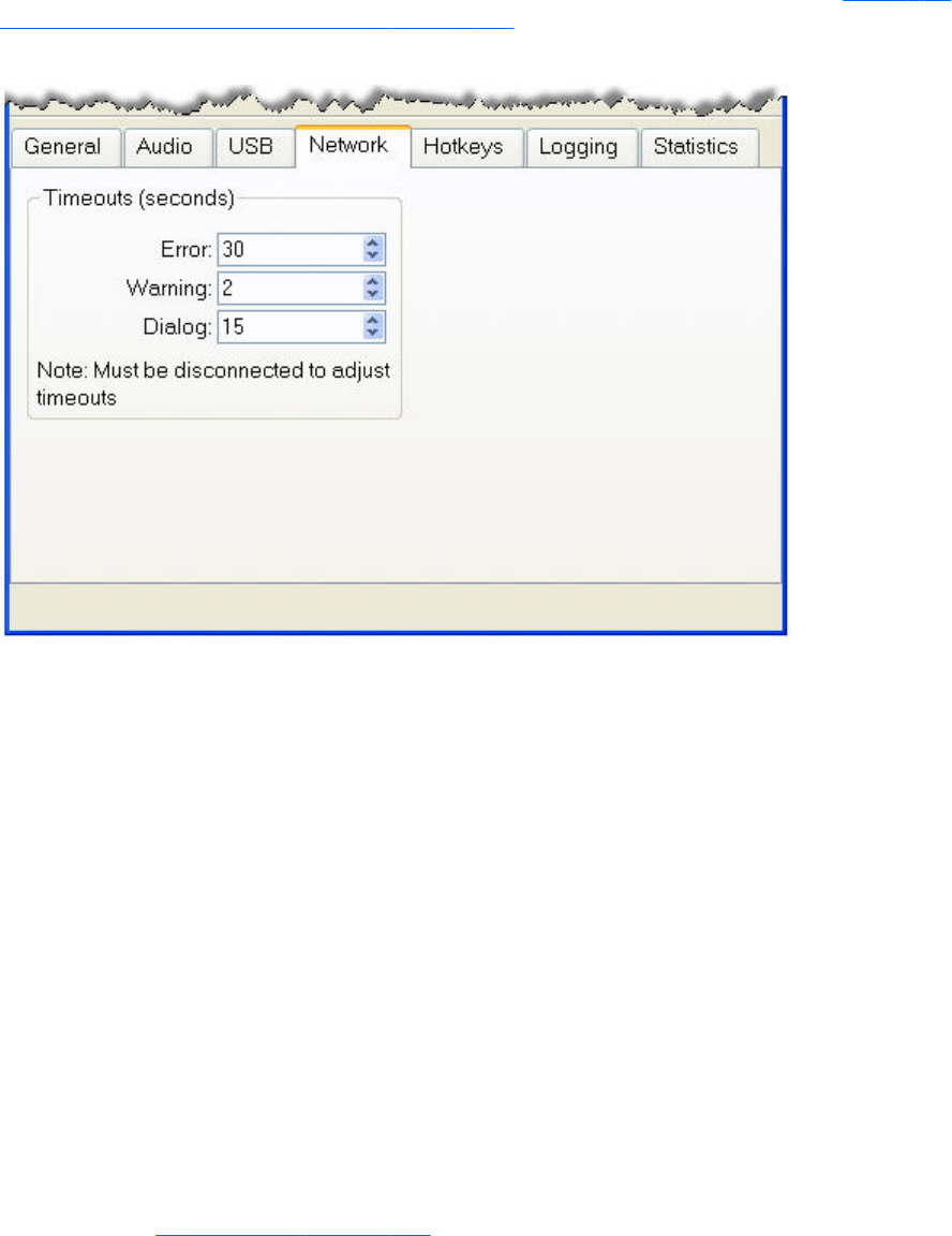
Adjusting Network timeout settings
The options available under the Network tab in the Receiver Control Panel are shown in Figure 6-22
Options available under the Network tab on page 148.
Figure 6-22 Options available under the Network tab
RGS supports three classes of user-settable timeouts:
1. Receiver network timeout properties—After the Receiver has established a connection to
the Sender, the Sender transmits sync pulses (consisting of network messages) to the Receiver
every second to permit the Receiver to determine connection integrity. If the Receiver fails to detect
the sync pulses, the Receiver compares the time since the last sync pulse was received to two user-
settable Receiver network timeout properties:
●Receiver warning timeout property
●Receiver error timeout property
2. Sender network timeout property—After the Receiver has established a connection to the
Sender, the Receiver likewise transmits sync pulses to the Sender every second to permit the
Sender to also determine connection integrity. If the Sender fails to detect the sync pulses, the
Sender compares the time since the last sync pulse was received to the user-settable Sender
network timeout property.
3. Dialog timeouts—Dialog timeouts control how long user interactions between the Sender and
Receiver are allowed to take.
The Receiver and Sender network timeout properties are discussed in the next section. Dialog timeouts
are discussed in Dialog timeouts on page 154.
148 Chapter 6 Advanced capabilities

Network timeouts
RGS uses TCP/IP over a standard computer network to transmit data. Although TCP/IP is a reliable
transport mechanism, it does not guarantee network packet delivery. The TCP/IP network stack
performs well on a relatively stable network. However, network issues beyond RGS can affect the
probability and timing of network packet delivery. Possible network issues include:
●Network over-subscription, resulting in congestion and packet loss
●CPU utilization by other processes and tasks, starving the TCP/IP network stack
●Incorrectly configured or malfunctioning network switches, routers, and network interfaces
●A disconnected network cable
To deal with such network issues, the Receiver and Sender support network timeout mechanisms to
provide notification to the user of network issues.
Receiver network timeouts
RGS provides two user-settable Receiver timeout properties to allow you to optimize RGS for your
particular network conditions (such as low-bandwidth or high-latency conditions). These properties
allow you to specify timeout values that, if exceeded, will cause the RGS Receiver to take specific
actions, such as displaying a warning dialog or closing the RGS connection. The two Receiver timeout
properties are:
●Receiver warning timeout property—If this value is exceeded, the Receiver displays a
network connection warning.
●Receiver error timeout property—If this value is exceeded, the Receiver closes the
connection.
The Receiver error and warning timeout properties can be set in the Receiver Control Panel (see Figure
6-23 Receiver Control Panel on page 150) and are specified in seconds. The Receiver timeout
properties can also be set in the rgreceiverconfig file or on a command line—in both of these cases, the
Adjusting Network timeout settings 149
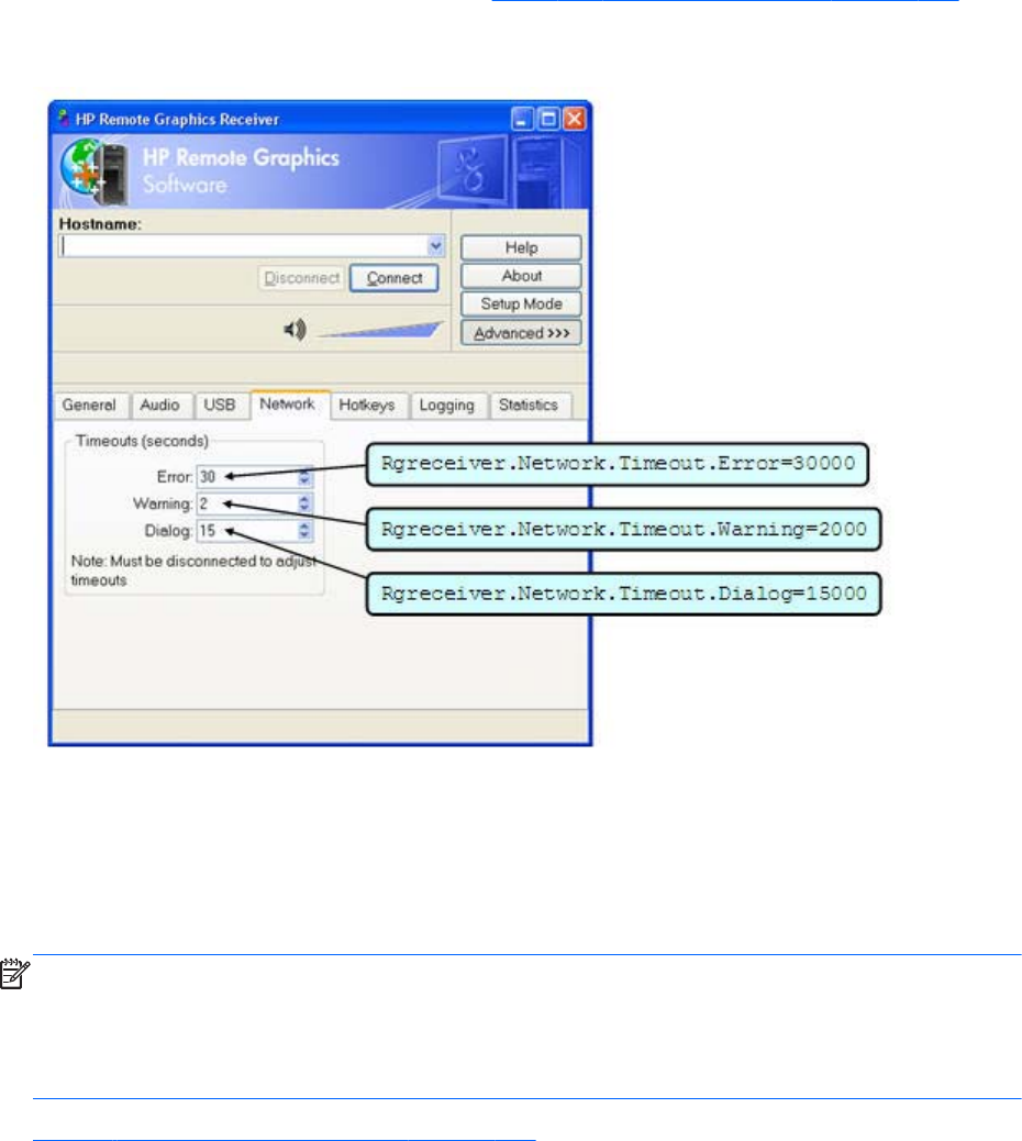
timeout properties are specified in milliseconds. Figure 6-23 Receiver Control Panel on page 150
shows the default Receiver timeout periods and the corresponding timeout properties.
Figure 6-23 Receiver Control Panel
If a temporary network disruption occurs for less time than the Receiver warning timeout property, the
Receiver will not display a warning, and the user will experience only a brief drop in Remote Display
Window interactivity. This means, for example, that a user moving or scrolling a window might see a
momentary decrease in interactivity. If the user is not interacting with the Remote Display Window
during a temporary network disruption, the network disruption may not even be noticeable (unless
dynamic content such as video fails to update at an appropriate rate).
NOTE: In many cases, the TCP/IP network stack is able to detect and resolve network errors, such as
a transmitted packet not being acknowledged. However, if a more serious problem occurs, such as a
network cable being unplugged from the Local Computer, the TCP/IP stack will notify the RGS Receiver
of a network exception. In this case, the RGS connection will be closed immediately, independent of
whether a network timeout property has been exceeded.
Figure 6-24 Receiver timeout sequence on page 151 shows the sequence of events commencing when
sync pulses cease being detected by the Receiver.
150 Chapter 6 Advanced capabilities
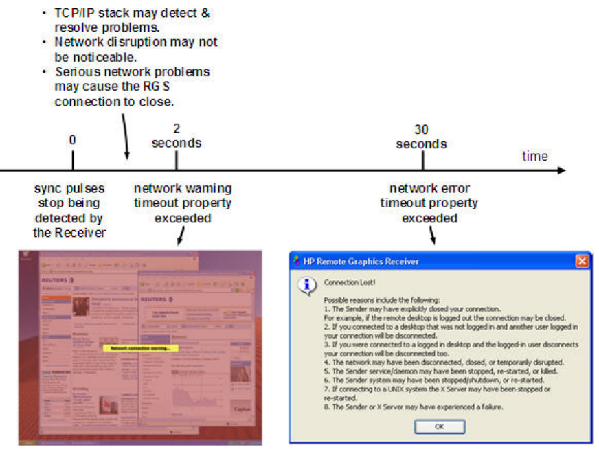
Figure 6-24 Receiver timeout sequence
After the Receiver warning timeout property has been exceeded (two seconds, in this case), the
Receiver Remote Display Window will dim and display a warning message to the user. The dimmed
window and warning message notify the user of the potentially stale contents in the Remote Display
Window. During this time, the Remote Display Window will appear unresponsive to the user. If
connectivity returns, the Remote Display Window will return to its normal appearance and interactivity.
If the connection loss extends beyond the Receiver error timeout property (30 seconds, in this case), the
Remote Display Window and the Receiver connection will be closed, and the "Connection Lost!" error
dialog will be displayed.
The recommended Receiver timeout strategy is to set a short warning timeout property and a longer
error timeout property. With these settings, the user is notified of potential network disruptions relatively
quickly while allowing sufficient time for the network to possibly recover. For networks with potential
disruptions greater than two seconds, a higher Receiver warning timeout property may be appropriate
to lessen distraction of the user.
Experience has demonstrated that 30 seconds is a reasonable Receiver error timeout property,
although some users adjust this property lower to force connections to close sooner. Higher settings,
such as 60 seconds, are often impractical because they force the user to wait an inordinate amount of
time before RGS closes the connection.
Adjusting Network timeout settings 151

Sender network timeout
The RGS Sender supports the Sender error timeout property, Rgsender.Network.Timeout.Error. This
property can be set only by using the rgsenderconfig file or on a command line—the Sender doesn’t
have a dialog to set this property. The Sender error timeout property is independent of the Receiver
timeout properties. The Sender begins by using the maximum of the Rgsender.Network.Timeout.Error
property and the Rgsender.Network.Timeout.Dialog property (see Dialog timeouts on page 154).
When the Receiver negotiates its connection to the Sender, it notifies the Sender of its error timeout
property. For sync pulse timeout purposes, the Sender adopts the minimum of:
Rgreceiver.Network.Timeout.Error
and the maximum of
{ Rgsender.Network.Timeout.Error AND Rgsender.Network.Timeout.Dialog }
For example, if the Sender error timeout property is 30 seconds and the Receiver error timeout property
is 20 seconds, the Sender will use 20 seconds for its sync pulse timeout because 20 seconds is the
minimum of both. If the user adjusts the Receiver error timeout property to 60 seconds, the Sender will
use a value of 30 seconds for sync pulse timeout because, again, 30 seconds is the minimum of both
error timeouts.
If a Sender sync pulse timeout occurs, the Sender will terminate its connection to the Receiver. Unlike
the Receiver, which displays warning and error messages, the Sender does not display a message prior
to terminating the connection. The user must initiate a reconnection from the Receiver to the Sender to
restore connectivity.
A relatively small Sender error timeout property is recommended. If the Receiver and Sender
connectivity is impacted by a network disruption, the Sender could take as long as its error timeout
property to determine the connectivity loss, and fully terminate the connection. During the time from the
actual network disruption until the Sender error timeout expires, the Sender will not send image updates
to other Receivers (if the Server is serving multiple Receiver connections). This will impact the
interactivity of other users for no apparent reason. After the Sender error timeout expires, the Sender
will terminate the faulty connection, and continue updating the other Receivers.
Network timeout issues
Listed below are several timeout-related issues and their potential causes.
●Remote Display Window repeatedly dims, and displays a connection warning
message—This is likely caused by frequent network disruptions between the Receiver and
Sender. The dimming of the display serves as a notification to the user that the Remote Display
Window may contain stale information. If frequent notifications are annoying, and the network
issues do not improve, see the section Adjusting Network timeout settings on page 148 and adjust
the Receiver’s warning timeout value found on the Receiver Control Panel or the property
Rgreceiver.Network.Timeout.Warning.
●The Remote Display Window dims, the Receiver disconnects, and displays a
“Connection closed” error dialog, but the user can often immediately connect
152 Chapter 6 Advanced capabilities

again—Most likely the network connectivity between the Receiver and Sender was temporarily
lost. Other possible problems include:
◦The Sender unexpectedly terminated.
◦The Remote Computer experienced a failure
◦The Remote Computer CPU utilization prevented the Sender from making progress,
◦The length of this connectivity loss exceeds the Receiver’s error timeout value, controlled by
the Receiver’s Rgreceiver.Network.Timeout.Error property so the Receiver disconnected.
If this condition persists, it is possible that network disruptions are exceeding the Receiver error
timeout value. If this is a network issue and is not resolvable, consider adjusting the error timeout
of the Receiver to reduce Receiver disconnection. Additionally, the Sender timeout might need to
be increased too. Please refer to Adjusting Network timeout settings on page 148 for further
details.
●When connecting to a Linux Remote Computer, the PAM authentication dialog
displayed by the Receiver does not appear long enough to enter the user’s
credentials such as username and password—This is likely caused by the Receiver
dialog timeout value being too small. See the section Dialog timeouts on page 154 for further
details on setting timeouts. The user should first check the Receiver Control Panel to determine the
Network dialog timeout setting and adjust as appropriate.
●When connecting to the Remote Computer, the authorization dialog is not
displayed long enough for the user to respond to it—This is likely caused by too small
of a Sender’s dialog timeout value. Please refer to Sender network timeout properties
on page 203 for further details on the property Rgsender.Network.Timeout.Dialog. The default
value for this property is 15 seconds.
●When connecting to a Linux Remote Computer, the PAM authentication often fails
—There are several reasons why this might occur:
◦PAM may be configured incorrectly
◦The user could be entering incorrect credentials
◦The timeouts are too short.
See Installing the Sender on Linux on page 86 to determine if PAM is correctly configured. See
Adjusting Network timeout settings on page 148 for further details on setting timeouts. The user
could try increasing the Receiver’s network dialog timeout as well as the Sender’s error and dialog
timeouts to see if this helps. If this does not help and the user is convinced that the timeouts are not
being exceeded, then it is likely a PAM authentication configuration problem.
●The Remote Display Window is not updating and appears to be hung—This is most
likely caused by a network disruption. You can adjust the warning timeout to get notification when
this occurs. You can also adjust the error timeout to disconnect and dismiss the Remote Display
Window sooner. The default warning timeout is two seconds. The default error timeout is 30
Adjusting Network timeout settings 153

seconds. See Adjusting Network timeout settings on page 148 for further details on setting the
Receiver timeouts.
●Increasing the Receiver error dialog timeout doesn’t appear to have an effect
and the Receiver still disconnects—This is likely caused by either:
◦A network failure resulting in detecting lost connectivity by the Receiver (resulting in a
disconnected connection)
◦The Sender timeouts are shorter than the Receiver’s timeouts, and the Sender disconnects the
Receiver.
It is not always the case that network error timeouts are honored. A network error timeout only
establishes an upper bound on the duration of retries before returning with an error. If the
computer determines that network connectivity is lost and an error returns by the network stack to
the Receiver, then the connection will disconnect sooner than the error timeout setting. If the
Sender’s timeout values are shorter than the Advanced capabilities Receiver’s, the Sender may
close the connection sooner than the Receiver, disconnecting the Receiver. If the issue continues,
consider increasing the Sender's error timeout value. See Adjusting Network timeout settings
on page 148 for further details on setting timeouts.
Dialog timeouts
RGS supports dialog timeouts, which specify how long user interactions between the Local Computer
and Remote Computer are allowed to take. The two dialog timeout properties are:
●Receiver dialog timeout property—This property specifies the maximum time that the
Receiver (Local Computer) will wait for a dialog response from the Remote Computer in response
to a message sent to the Remote Computer. It also specifies how long dialogs initiated by the
Remote Computer will be displayed to the user on the Local Computer.
●Sender dialog timeout property—This property specifies the maximum time that a message,
originating from the Receiver, will be displayed on the Remote Computer. It also specifies how
long the Remote Computer Sender will wait for a dialog response from the Receiver.
For example, assume that a local user is attempting to connect to a Remote Computer. Assume,
furthermore, that another user is already logged into the Remote Computer (this person is therefore the
primary user). The Sender will prompt the primary user for authorization to connect the local user to the
Remote Computer. The duration of this prompt is set by the Rgsender.Network.Timeout.Dialog property.
The Receiver property Rgreceiver.Network.Timeout.Dialog limits how long the Receiver will wait for a
response from the Remote Computer before returning failure.
If the Rgsender.Network.Timeout.Dialog timeout expires without action by the primary user, the Sender
dialog exits, and connection is denied by default. If the Sender times out, the Receiver will also time out
(based on its Rgreceiver.Network.Timeout.Dialog property) because no authorization reply will be
returned by the Sender.
In the previous example, the dialog was displayed on the Remote Computer. An example of a dialog
being displayed on the Local Computer follows. When a Receiver connects to a Sender running Linux,
the Pluggable Authentication Module (PAM) on the Sender attempts to authenticate the connection. In
this case, the PAM subsystem invokes a PAM conversation/callback function to the Receiver, causing
the Local Computer to prompt the user with a PAM message dialog. The dialog typically requests a
username and password. The timeout for the dialog on the Receiver is controlled by the
154 Chapter 6 Advanced capabilities

Rgreceiver.Network.Timeout.Dialog property. If this timeout expires without the local user entering a
username and password, the Receiver will remove the dialog.
NOTE: The property Rgreceiver.Network.Timeout.Dialog does not control the duration of all dialogs
displayed by the Receiver. For example, the authentication dialog for a Windows Sender connection
displayed by the Receiver for username and password does not have an associated timeout since it is
not an incoming message from the Sender to the Receiver. This dialog will be displayed indefinitely
until the user responds "OK" or "Cancel" to its requests
The Receiver dialog timeout property, Rgreceiver.Network.Timeout.Dialog, can be set using the
Receiver Control Panel as shown in Figure 6-23 Receiver Control Panel on page 150, and has a
default value of 15 seconds. This property can also be set using the rgreceiverconfig file and from a
command line.
The Sender dialog timeout property, Rgsender.Network.Timeout.Dialog, can only be set using the
rgsenderconfig file and from a command line—there is no dialog on the Sender for setting this
property. The default value of this property is also 15 seconds.
The 15 second Receiver and Sender dialog timeouts should support most authorization and
authentication scenarios. For more complex scenarios requiring additional time, the user should adjust
both the Receiver and Sender dialog timeouts appropriately.
Adjusting Network timeout settings 155
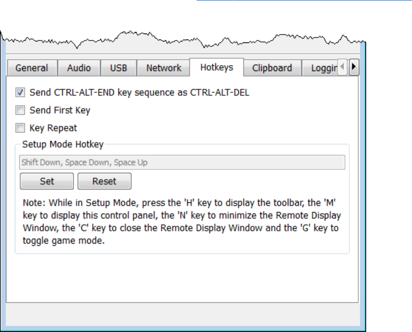
Hotkeys
Hotkeys are key sequences that cause special action to be taken by the Receiver. Such key sequences
are processed by the Receiver, and are not sent to the Remote Computer. However, a hotkey sequence
may initiate some type of interaction with the Remote Computer. The Receiver Control Panel provides a
number of options under the Hotkeys tab (see Figure 6-25 The Hotkeys tab options on page 156).
Figure 6-25 The Hotkeys tab options
The options available under the Hotkeys tab are:
●Send CTRL-ALT-END key sequence as CTRL-ALT-DEL: On some computers, the operating
system will intercept the CTRL-ALT-DELETE key sequence, and will not forward it to the Receiver. For
example, assume that the Local Computer is running Windows, and that the local user enters the
key sequence CTRL-ALT-DELETE in a Remote Display Window for the purpose of logging into the
Remote Computer. However, instead of forwarding this key sequence to the Remote Computer,
Windows on the Local Computer will respond to these keys, and bring up the Windows Security
dialog on the Local Computer.
This checkbox can be used to circumvent this behavior. When checked, the local user can enter
the key sequence CTRL-ALT-END in a Remote Display Window. The Receiver recognizes CTRL-ALT-
END as a signal to send a CTRL-ALT-DELETE sequence directly to the Remote Computer. The CTRL-
ALT-DELETE sequence can also be sent using the Remote Display Window Toolbar.
●Setup Mode Hotkey: The text dialog and the Set and Reset buttons allow you to redefine the
Setup Mode hotkey sequence from its default value. As shown in the Receiver Control Panel of
156 Chapter 6 Advanced capabilities

Figure 6-25 The Hotkeys tab options on page 156, the default hotkey sequence to activate Setup
Mode is:
◦Press and hold down the Shift key.
◦At the same time, press then release the space bar—this activates Setup Mode. You will
remain in Setup Mode until you release the Shift key.
●Send First Key: This checkbox controls how the Receiver responds to a key sequence. For
example, the default Setup Mode hotkey consists of a Shift Press, Space Press, and Space
Release. When the Receiver sees a shift key press, this key event is not immediately sent to the
Remote Computer. Instead, the Receiver retains the event to determine if the next keystroke forms a
hotkey sequence. If the next key pressed is not space, the Receiver immediately forwards all key
events to the Remote Computer.
Some user applications, in order to function correctly, require that the first key press event arrive
separately from subsequent key events. If this is the case, check the Send First Key checkbox to
enable the immediate transmission of the first key in a hotkey sequence to the Remote Computer.
Note that, in addition to sending the first key to the Remote Computer, the key sequence is still
processed by the Local Computer.
●Key Repeat: When using a hotkey sequence, Windows injects repeating shift down events in
response to the Shift key being held down. By default, the Receiver ignores these key repeats.
Processing of key repeats can be enabled by checking this box if it’s required for your
applications.
NOTE: If Key Repeat is enabled, the hotkey sequence will not trigger Setup Mode, so the
sequence must be typed faster if this setting is enabled.
●Additional hotkeys—The following hotkeys are also supported; these hotkeys can be entered
as either upper case or lower case:
◦“H”—Toggles the Remote Display Window Toolbar on and off (see Remote Display Window
Toolbar on page 106)
◦“M”—Restores the Receiver Control Panel if it has been minimized (iconified). Also brings the
Receiver Control Panel to the front if it is obscured by other windows.
◦“N”—Minimizes (iconifies) the Remote Display Window
◦“C”—Closes the Remote Display Window, which terminates the RGS connection
◦“G”—Toggles “Game Mode.” Game Mode enables relative cursor movements instead of
absolute cursor movements. See Game Mode on page 124 for more details.
If Setup Mode is activated by the hotkey sequence (as opposed to the Setup Mode button), and you
have multiple Remote Display Windows on your computer, you can bring up the Remote Display
Window selection dialog to view a thumbnail image of each Remote Display Window (see Starting the
Receiver in Directory Mode on page 172)
Changing the Setup Mode hotkey sequence
RGS allows you to change the Setup Mode hotkey sequence from its default value of:
Hotkeys 157

Shift Down, Space Down, Space Up
In defining a new Setup Mode hotkey sequence, the following keys can be used:
●LCtrl, RCtrl, Ctrl— Specifies a left, right or side-insensitive Ctrl key, respectively.
●LAlt, RAlt, Alt— Specifies a left, right or side-insensitive Alt key, respectively.
●Shift
●Space
Every sequence must begin with Ctrl, Alt, or Shift. Two actions are associated with each key:
●Down: Specifies a key press.
●Up: Specifies a key release.
To change the hotkey sequence, first press the Set button under the Hotkeys tab. Then press and
release the keys that you want to form the Setup Mode hotkey sequence. The first key that you enter
must be held down until you are done entering the other key(s). This is identical to the process of
actually activating Setup Mode, where the first key is likewise held down while the other key(s) are
pressed and released, followed by releasing of the first key.
As you press and release the keys, the key sequence is displayed in the dialog box.
To define a sequence that is side-insensitive, you’ll need to modify the property value from outside of
the GUI while RGS is not running. See Receiver hotkey properties on page 192 for information on
modifying the sequence from outside of the GUI.
Pressing the Reset button on the Receiver Control Panel restores the Setup Mode hotkey sequence to its
original default values.
158 Chapter 6 Advanced capabilities
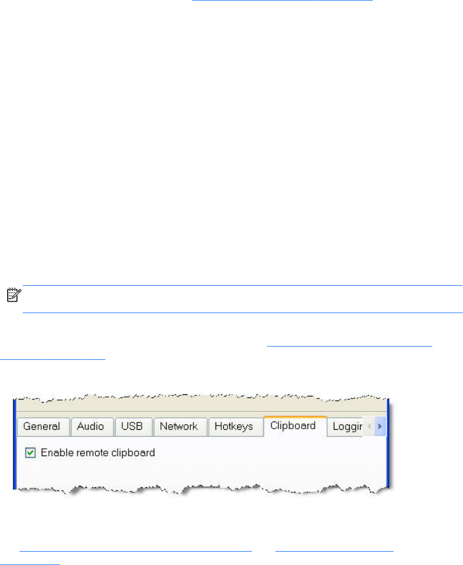
Remote Clipboard operation
For an overview of Remote Clipboard, see Remote Clipboard overview on page 45. Remote Clipboard
enables you to cut or copy data between a window on the Local Computer and a Remote Window
(provided that the applications being used support cut/copy/paste functionality). Beginning with RGS
5.3.0, Remote Clipboard cut and paste of ANSI text data is supported between Windows Receiver
systems and Linux Sender systems. Successful operation of the clipboard on Linux systems in RGS will
depend on how the application interacts with the graphical desktop's clipboard. Some applications'
use of the clipboard may not work as expected with RGS Remote Clipboard. With most applications,
you will need to perform cut or copy actions by Highlighting the text of interest and selecting the Cut or
Copy action normally found in the application's "Edit" menu.
Following installation, Remote Clipboard on Windows can be enabled or disabled via a toggle in the
Receiver's controls.
Remote Clipboard on Linux is installed by default and is enabled or disabled via a toggle in the
Receiver's controls.
Both cut and paste, and copy and paste, are supported in the following scenarios at RGS 5.3.0:
●Between a Local Window and a Remote Display Window (in both directions) — The Remote
Computer may be running Windows or Linux. The Local Computer must be running Windows.
●Between two Remote Display Windows (in both directions) — In this case, the Local Computer can
be running either Windows or Linux; the Remote Computers may be running Windows or Linux.
NOTE: For simplicity, the phrase “cut and paste” is used hereafter to refer to both cut and paste,
as well as copy and paste.
The Enable remote clipboard checkbox under the Clipboard tab in the Receiver Control Panel
allows the user to enable or disable Remote Clipboard (see Figure 6-26 Enable remote clipboard
checkbox on page 159).
Figure 6-26 Enable remote clipboard checkbox
Beginning with RGS 5.4.8, the clipboard can be enabled to work on a limited permissions receiver
window for collaboration mode.
See Receiver Remote Clipboard properties on page 193 and Sender clipboard property
on page 205, for information on the Remote Clipboard properties.
Remote Clipboard operation 159
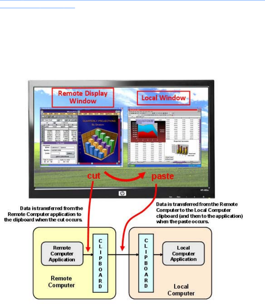
Remote Clipboard data transfers
Figure 6-27 Transfer of data when a cut and paste is performed from a Remote Display Window to a
Local Window on page 160 shows the data transfer that occurs when a cut and paste is performed
using Remote Clipboard. In this example, the cut occurs from within the Remote Computer application
(as initiated from the Remote Display Window), and the paste occurs into the Local Computer
application (via the Local Window). When the cut is performed, the data that is cut from the Remote
Computer application is transferred to the clipboard on the Remote Computer. When the paste occurs,
the clipboard data is transferred from the Remote Computer clipboard to the Local Computer clipboard,
and then pasted into the Local Computer application.
Figure 6-27 Transfer of data when a cut and paste is performed from a Remote Display Window to
a Local Window
The above demonstrates delayed rendering. Instead of transferring data from the Remote Computer to
the Local Computer when the cut occurs, the data transfer is delayed until the paste occurs. This reduces
network traffic by eliminating unnecessary data transfers.
Doing a cut and paste in the other direction (from the Local Window to the Remote Display Windows)
works in the same manner—the data that is cut is held in the clipboard on the Local Computer until the
paste occurs on the Remote Computer, at which time the clipboard data is transferred to the Remote
Computer.
160 Chapter 6 Advanced capabilities
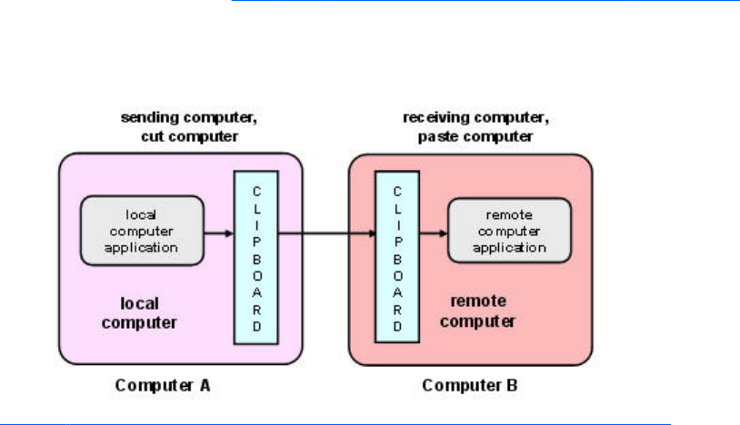
As we’ve seen, the terms “Remote Computer” and “Local Computer” have very specific meanings in the
context of RGS. In the context of Remote Clipboard, however, we use terms that are centric to each
computer involved in a Remote Clipboard operation. If a cut and paste is being performed from
Computer A to Computer B, Computer A will refer to itself (for example, in the DEBUG LOG) as the
local computer, while referring to Computer B as the remote computer. This is independent of which
computer is the actual Local Computer or Remote Computer from an RGS connection perspective.
Continuing with the example of a cut and paste from Computer A to Computer B, Computer A is also
referred to as the sending computer or cut computer, while computer B is referred to as the receiving
computer or paste computer. Figure 6-28 Cut and paste computer nomenclature on page 161 shows
this nomenclature. When discussing Remote Clipboard operation, we’ll generally use this nomenclature
because it is independent of which computers are the Remote or Local Computers.
Figure 6-28 Cut and paste computer nomenclature
Figure 6-29 Cutting and pasting between Remote and Local Computers on page 162 show a system
consisting of three Remote Computers connected by RGS to the Local Computer. The three desktops of
the Remote Computers are displayed in three Remote Display Windows on the Local Computer. In this
system, assume the Local Computer user has just performed a cut operation on the cut computer (via
one of the Remote Display Windows). At this point, the user can do a paste to any (or all) of the paste
computers. If a paste is done to paste computer #1 or paste computer #2, this will constitute a Remote
Computer-to-Remote Computer (RGS Sender-to-Sender) paste because both the cut computer and the
paste computer are Remote Computers.
If the user does a paste to paste computer #3, this will constitute a Remote Computer-to-Local Computer
(RGS Sender-to-Receiver) paste because the paste computer is the Local Computer.
Remote Clipboard operation 161
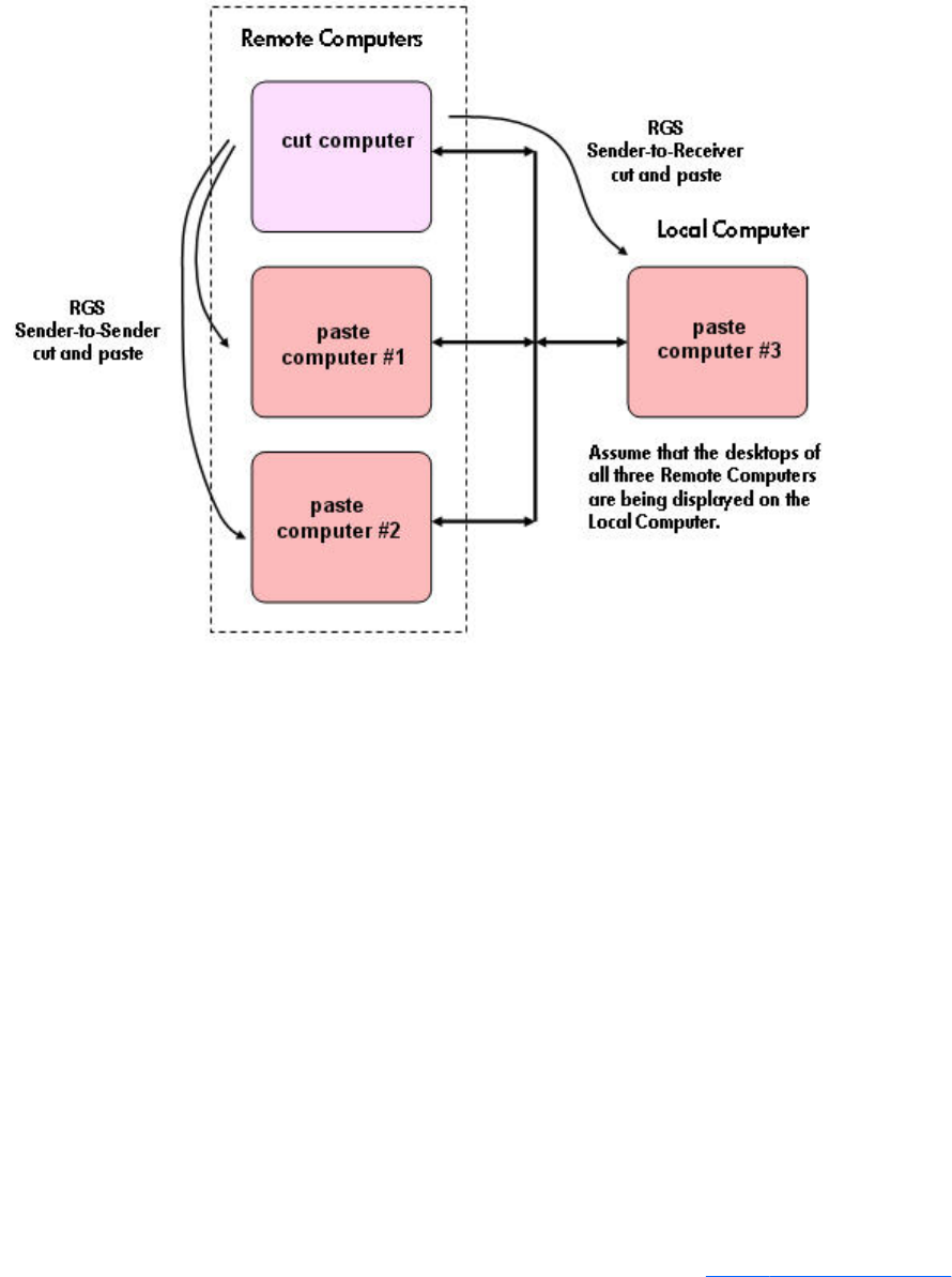
Figure 6-29 Cutting and pasting between Remote and Local Computers
Remote Clipboard filtering
When a cut is performed, applications typically store their data in the clipboard in multiple formats. For
a word processing application, the application might store data in the clipboard as both ASCII text and
Rich Text Format. This increases the likelihood that, when the paste occurs, there will be a format
recognized by the receiving application. For example, when a cut is performed within Microsoft Word,
one of the clipboard formats supported by Word is ASCII text. This allows a paste into, for example,
Notepad, which accepts ASCII text.
Some data formats, like HTML, may present problems when pasted into a remote computer. HTML, for
example, does not store images in the clipboard, but instead stores links to where the images reside (on
the local computer). When the HTML is pasted into the remote computer, the pasted links will no longer
point to a valid location.
There are other potential problems, such as links to websites. Consider the act of cutting and pasting
from Excel on a local computer to Excel on a remote computer. When pasted on the remote computer,
Excel data on the Office Clipboard that contains links to websites will attempt to access those websites.
If the remote computer is not connected to the Internet, Excel may hang trying to access the websites.
To provide the ability to handle such problems, Remote Clipboard implements user-settable filtering to
allow control of which clipboard formats can be used in cut and paste operations. Filtering of clipboard
formats is performed on the computer receiving the cut and paste data. See Figure 6-30 Receiving-side
162 Chapter 6 Advanced capabilities
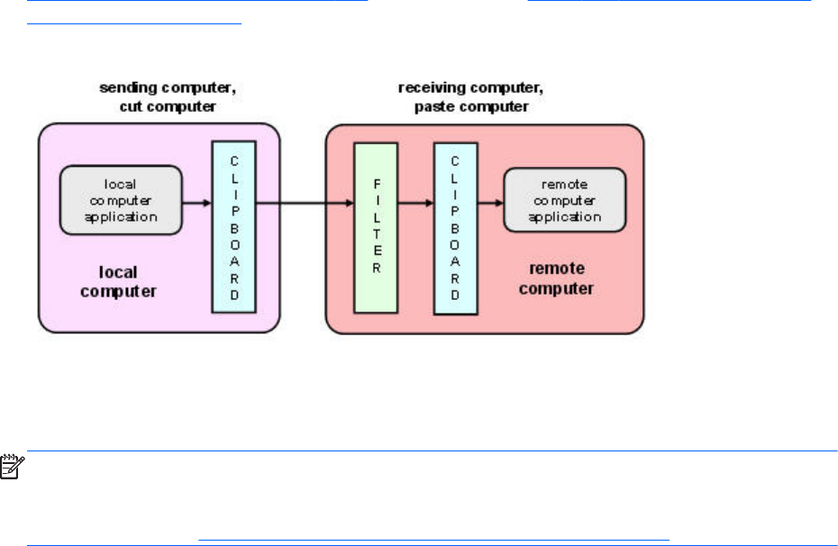
filtering of cut and paste data on page 163, which expands on Figure 6-28 Cut and paste computer
nomenclature on page 161 to show receiving-side filtering.
Figure 6-30 Receiving-side filtering of cut and paste data
The filter parameter is specified by this RGS Receiver Remote Clipboard property:
Rgreceiver.Clipboard.FilterString
NOTE: This property is for advanced users only. The property string should be changed from its
default value only if Remote Clipboard doesn’t support the clipboard format required by your
application. For more information on clipboard formats, see the Microsoft Developer Network article
Clipboard Formats at http://msdn2.microsoft.com/en-us/library/ms649013.aspx.
This property contains a list of clipboard formats allowed to be transferred using Remote Clipboard.
Therefore, this property is a keep filter, not a reject filter. The string is a regular expression, and is used
by the receiving computer to specify the clipboard formats that it will accept. The rgreceiverconfig file
contains the following commented-out entry for this property, which indicates the default clipboard
formats supported by RGS:
# Rgreceiver.Clipboard.FilterString="|1|2|7|8|13|16|17|Ole Private Data|
Object Descriptor |Link Source Descriptor|HTML Format|Rich Text Format|
XML Spreadsheet|"
The default clipboard formats are:
●1 (CF_TEXT)—Text format. Each line ends with a carriage return/linefeed (CR-LF) combination. A
null character signals the end of the data. Use this format for ANSI text.
●2 (CF_BITMAP)—Bitmap format.
●7 (CF_OEMTEXT)—Text format containing characters in the OEM character set. Each line ends
with a carriage return/linefeed (CR-LF) combination. A null character signals the end of the data.
●8 (CF_DIB)—A memory object containing a BITMAPINFO structure followed by the bitmap bits.
●13 (CF_UNICODETEXT)—Unicode text format. Each line ends with a carriage return/linefeed (CR-
LF) combination. A null character signals the end of the data.
●16 (CF_LOCALE)—Locale identifier associated with text in the clipboard
●17 (DIBV5)—Bitmap color space and bitmap data
Remote Clipboard operation 163
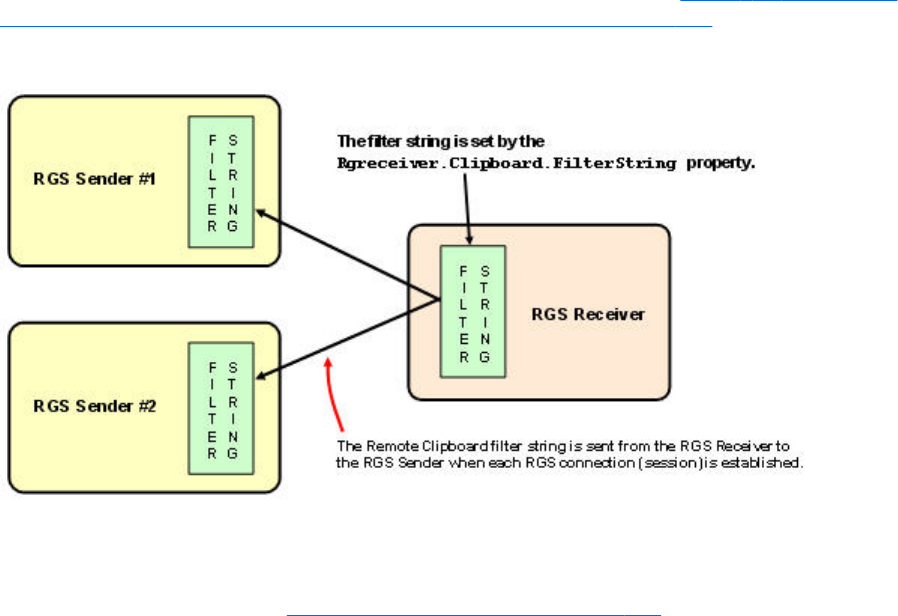
●Ole Private Data—A private application format understood only by the application offering the
format.
●Object Descriptor—OLE2 object descriptor
●Link Source Descriptor—Link to OLE2 object
●HTML Format—Text is in Hypertext Markup Language format
●Rich Text Format—A text format that includes special formatting features, such as bold, italics, and
centering.
●XML Spreadsheet—A format created by Microsoft to allow Excel spreadsheets to be saved in XML
(Extensible Markup Language) format. This format is supported by other applications as well.
The Remote Clipboard system uses the filter string to avoid transmission of unneeded clipboard formats
across the network—only formats specified by the filter string are passed over the network from the cut
computer to the paste (receiving) computer.
Because the filter string is an RGS Receiver-specified property, and because the paste computer can be
any computer (RGS Sender or Receiver), RGS communicates the filter string from the RGS Receiver to
each RGS Sender whenever a Receiver/Sender connection is established (see Figure 6-31 Transmission
of the filter string property from the RGS Receiver to the RGS Sender on page 164).
Figure 6-31 Transmission of the filter string property from the RGS Receiver to the RGS Sender
Using the RGS log to detect clipboard problems
As described in the next section, Receiver and Sender logging on page 167, both the RGS Receiver
and the RGS Sender have the ability to log various types of information to log files during their
operation. If the logging level is set to DEBUG on the Receiver and Sender, Remote Clipboard
information will be stored in the Receiver and Sender log files. These log files can then be used to
detect and resolve Remote Clipboard problems.
Remote Clipboard entries in the log files have the text below preceding the Remote Clipboard
information. In particular, the string “(format filter)” identifies each log file entry that contains Remote
164 Chapter 6 Advanced capabilities
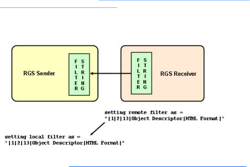
Clipboard information. In this section, the text preceding the Remote Clipboard information will not be
shown.
11-08-08 00:26:14 DEBUG - (format filter) ...Remote Clipboard information...
To demonstrate use of the RGS logs to view Remote Clipboard information on the Receiver and Sender
computers, an example is presented in which a copy and paste is performed from a Sender computer
to a Receiver computer. The steps in this example are:
1. Set the Rgreceiver.Clipboard.FilterString="|1|2|13|Object Descriptor|HTML Format|"
2. Establish an RGS connection from the Receiver to the Sender.
3. Open Notepad on the Receiver computer.
4. Open Notepad on the Sender computer (via the Remote Display Window) and enter some text.
5. Highlight the text in the Sender Notepad window, and then select Copy.
6. Do a Paste of the text into the Notepad window on the Receiver computer.
To set the Rgreceiver.Clipboard.FilterString as shown above, the rgreceiverconfig configuration file is
modified to specify the property:
Rgreceiver.Clipboard.FilterString="|1|2|13|Object Descriptor|HTML
Format|"
The RGS Receiver is stopped, and then restarted to ensure this property is used. When an RGS
connection is established, the RGS Receiver sends this filter string to the RGS Sender. The log file entries
generated by this activity are shown in Figure 6-32 Transmission of the filter string property from the
RGS Receiver to the RGS Sender on page 165. From the RGS Receiver’s perspective, it’s setting a
“remote filter” (on the Sender). From the Sender’s perspective, it’s setting its local filter string when it
receives the filter string from the Receiver.
Figure 6-32 Transmission of the filter string property from the RGS Receiver to the RGS Sender
Now that the filter string has been sent from the Receiver to the Sender, we’ll switch to the Remote
Clipboard nomenclature of Figure 6-30 Receiving-side filtering of cut and paste data on page 163.
Remote Clipboard operation 165
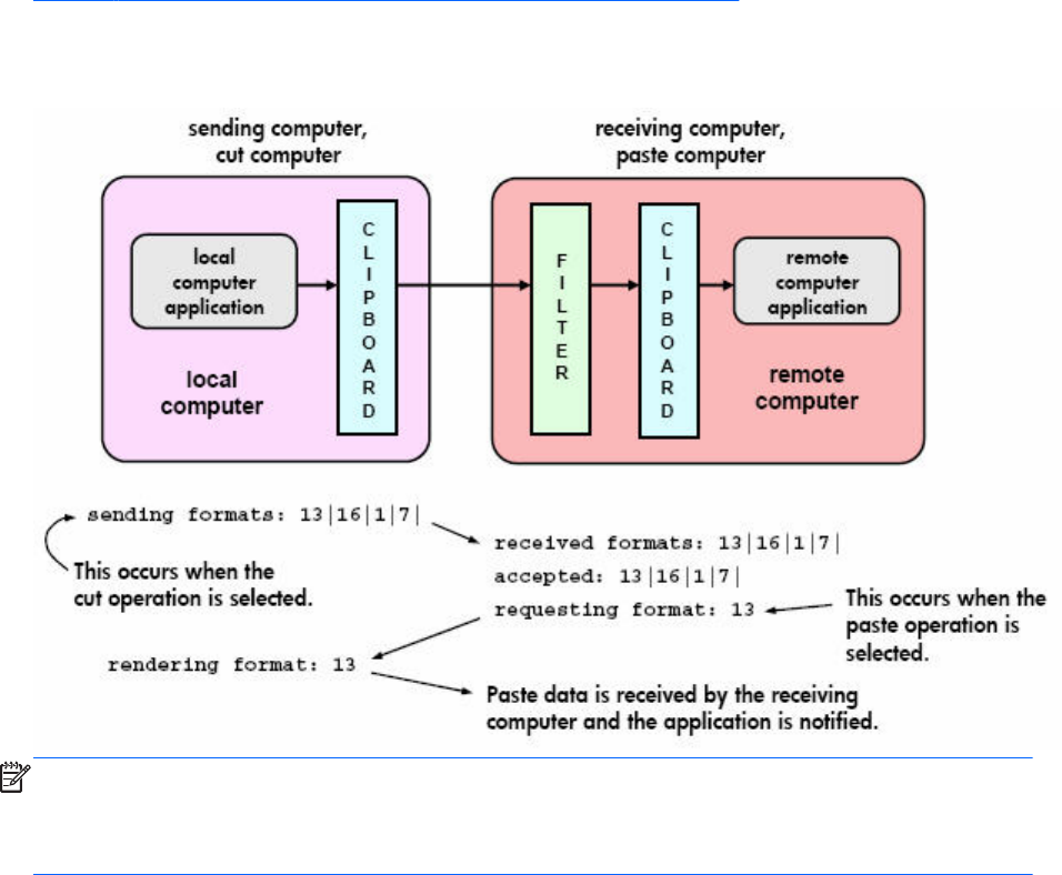
Figure 6-33 Remote Clipboard log entries for cut and paste on page 166 shows the Remote Clipboard
log entries as the cut and paste is performed.
Figure 6-33 Remote Clipboard log entries for cut and paste
NOTE: If the clipboard on either the Local or Remote Computer already contains content at the time
the RGS connection is established, a sending formats entry will appear in the log file of that computer
preceding the setting filter log entry. The sending formats log entry is due to the clipboard contents
being sent to the Remote Computer when the RGS connection is first established.
166 Chapter 6 Advanced capabilities
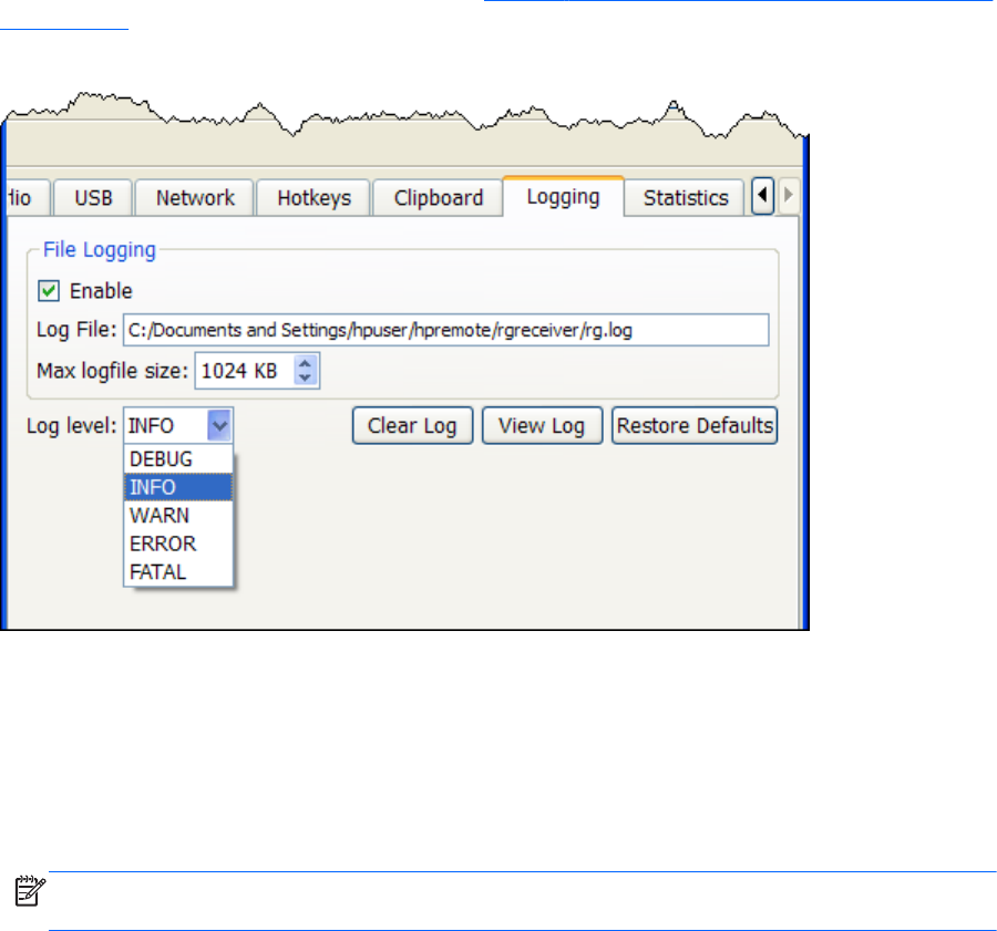
Receiver and Sender logging
Both the RGS Receiver and the RGS Sender have the ability to log various types of information to files
during their operation. Receiver logging can be enabled from the Receiver Control Panel, while Sender
logging is controlled by a file on the RGS Sender. Both types of logging are described below.
Receiver logging
The RGS Receiver logs various types of information during its operation. The Receiver Control Panel
Logging tab allows you to set a number of the logging parameters, such as whether logging is
enabled and the location/name of the log file(see Figure 6-34 Options available under the Logging tab
on page 167).
Figure 6-34 Options available under the Logging tab
The options available under the Logging tab are:
●File logging—Enables logging to the specified Log File. The spinbox for Max logfile size limits
the maximum logfile size.
●Log level—Determines the level of information that is logged. For example, if WARN is selected,
the log file will contain information of type WARN and below, that is, WARN, ERROR, and
FATAL. To log all information generated by the Receiver, select DEBUG.
NOTE: In order to log Remote Clipboard activities on the Receiver, DEBUG-level logging must
be selected.
●Clear Log—Clears the contents of the log file.
●View Log—Displays the contents of the log file in a window.
●Restore Defaults—Resets all logging settings to default values.
Receiver and Sender logging 167
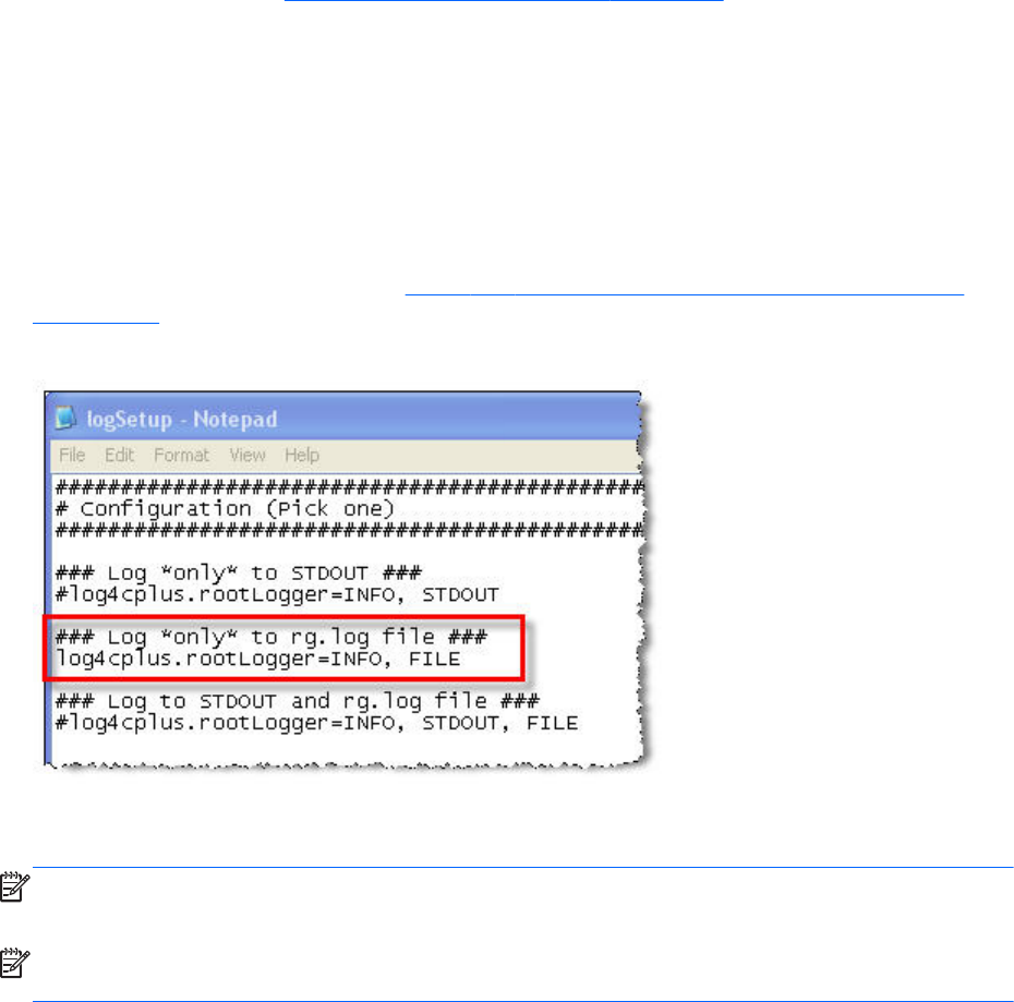
Sender logging
RGS Sender logging is not controlled by a GUI—instead, Sender logging is controlled by a particular
file on the RGS Sender. In Installing the Sender on Windows on page 58, the following command line
option for Rgsender.exe is described:
-l logSetupFile—Specifies the "logSetupFile" file used to describe various logging parameters for
Sender error and informational output. This file is used to determine where the output goes (to a file or
to standard error) as well as the type of output logged (INFO or DEBUG). At installation, the Sender
default is with "-l logSetup" turned on, where the logSetup file in the installation directory is set for
output to a file named rg.log at INFO debug level.
Unless this command line option is used to change the logSetup file, the default logSetup file in the
Sender installation folder (C:\Program Files\Hewlett-Packard\Remote Graphics Sender) is used. The
first few lines of logSetup are shown in Figure 6-33 Remote Clipboard log entries for cut and paste
on page 166.
Figure 6-35 logSetup file
The highlighted, uncommented line specifies that INFO-level logging is used. If another logging level is
required, edit the file to replace INFO with any of the following: DEBUG, WARN, ERROR, or FATAL.
NOTE: The logSetup file is set to read-only during Sender installation, so you’ll need to uncheck the
Read-only property to edit the file.
NOTE: In order to log Remote Clipboard activities on the Sender, DEBUG-level logging (not the
default INFO-level logging) must be specified in the logSetup file.
168 Chapter 6 Advanced capabilities
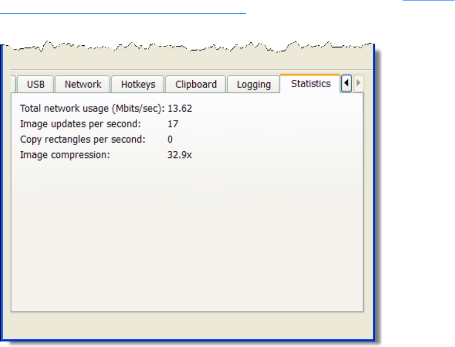
Statistics
The options available under the Statistics tab in the Receiver Control Panel are shown in Figure 6-36
Options available under the Statistics tab on page 169.
Figure 6-36 Options available under the Statistics tab
The Statistics tab displays aggregate data for all connected sessions.
●Total network usage (Mbits/sec)—The combined network traffic received from all Remote
Computers.
●Image updates per second—The combined number of image updates per second received
from all connections.
●Copy rectangles per second—The combined number of copy updates per second received
from all connections.
●Image compression—The compression ratio of the update stream. In a multi-connection
environment the value is from the Remote Display Window that currently has the keyboard focus. If
none of the Remote Display Windows have focus the value will be zero. In a single-connection
environment the value will be always available even if the Remote Display Window does not have
focus.
Statistics 169

7 Using Directory Mode
Directory Mode enables the local user to automatically open connections to multiple Remote Computers
based on the computers assigned to each user. When the user starts the Receiver in Directory Mode,
the Receiver looks for a directory file containing user names and their assigned Remote Computers. The
Receiver reads this file to identify the Remote Computers assigned to the current user, and then attempts
to automatically connect to each specified Remote Computer. The directory file may contain multiple
users with a list of Remote Computers assigned to each user. The default directory file used by the
Receiver is:
C:\Program Files\Hewlett-Packard\Remote Graphics Receiver\directory.txt
After the directory file name is determined, the Receiver automatically connects to the Remote
Computers specified in this file for the named user.
Directory file format
Often, the directory file is a common file for a group, department, organization, or an entire company.
The directory file can manage and administer the Remote Computer assignments for any number of
users. HP recommends that you save the directory file on a readily-accessible network file share or
mapped drive so that each RGS Receiver can read the file at start-up.
The directory file is a text file with the following format for each local user:
domainName localuser remotecomputer1 remotecomputer2 ... remotecomputerN
170 Chapter 7 Using Directory Mode
where:
●The domainName on a Windows computer depends upon the environment the currently logged-in
user is operating within. If the user is logged onto their domain account, this means they have
logging onto an account specified by Microsoft Active Directory directory services. If the domain
account is worldwide\sally, the name of the Windows domain is “worldwide” and will be
used as the domainName for directory mode.
If the user is logged onto the computer with a “local” account, sally_computer\sally for
instance, the domainName used for directory mode is “sally_computer.” This typically will
be a computer that is either standalone or part of a WORKGROUP not using Active Directory
directory services. The computer name such as sally_computer can be found by executing the
command hostname in a “command window.”
For Linux users, use “UNIX” as the domainName.
●localuser is the name of the local user
●remotecomputer1, remotecomputer2,...remotecomputerN are the Remote Computers assigned to
the local user, as specified by either a hostname or an IP address.
For example, the following directory file specifies the Remote Computers for users Sally and Joe in a
Microsoft Active Directory directory services environment:
worldwide sally RC_1 RC_2 RC_3
worldwide joe RC_4 RC_5 RC_6
In the next example, the directory file specifies the Remote Computers for users Sally and Joe in a
standalone or WORKGROUP environment.
sally_computer sally RC_1 RC_2 RC_3
joe_computer joe RC_4 RC_5 RC_6
In the above examples:
●Local user sally is assigned Remote Computers RC_1, RC_2, and RC_3
●Local user joe is assigned Remote Computers RC_4 RC_5, and RC_6
If the domain name, user name, or Remote Computer contains white-space characters, the name can be
enclosed in double-quotes, as follows:
"domain 1" "sally user" "RC 1" "RC 2" "RC 3"
"domain 1" "joe user" "RC 4" "RC 5" "RC 6"
The domain name does not apply when using the directory file for Linux users. Instead, use the keyword
"UNIX" in place of the domain name. For example:
UNIX sally RC_1 RC_2 RC_3
Comment lines in the directory file are preceded by the “#” character in the first column.
Directory file format 171
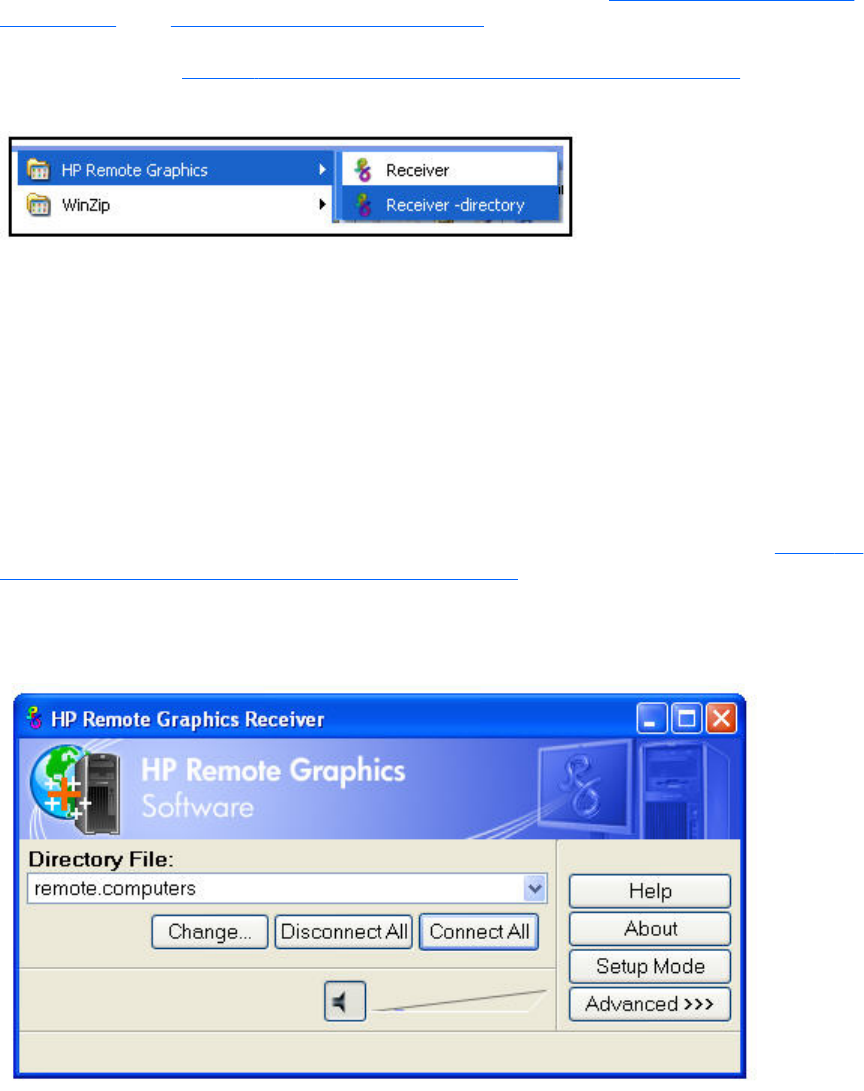
Starting the Receiver in Directory Mode
Before attempting a connection in Directory Mode for the first time, HP recommends that you verify that
RGS can connect to each computer individually in Normal Mode (see Using RGS in Normal Mode
on page 101). The Pre-connection checklist on page 91 can be used to verify that the computer and
network parameters are set correctly. After Normal Mode connectivity is verified, start the Receiver in
Directory Mode (see Figure 7-1 Starting the Receiver in Directory Mode on page 172).
Figure 7-1 Starting the Receiver in Directory Mode
Alternately, the Receiver can be started in Directory Mode from a command line, using either of the
following:
C:\Program Files\Hewlett-Packard\Remote Graphics Receiver\rgreceiver.exe -
directory “file”
C:\Program Files\Hewlett-Packard\Remote Graphics Receiver\rgreceiver.exe -
directory
If a file name is specified after -directory, the Receiver will use that file as the directory file. If no file
name is specified, the user is prompted by RGS to specify the path and name of the directory file.
In Directory Mode, the Receiver Control Panel displays the name of the directory file (see Figure 7-2
The Receiver Control Panel in Directory Mode on page 172). The Change button enables you to
specify a different directory file. The Connect All button is used to establish a connection to the
Remote Computers listed in the directory file.
Figure 7-2 The Receiver Control Panel in Directory Mode
After clicking Connect All, you’ll need to independently authenticate and log into each Remote
Computer.
172 Chapter 7 Using Directory Mode
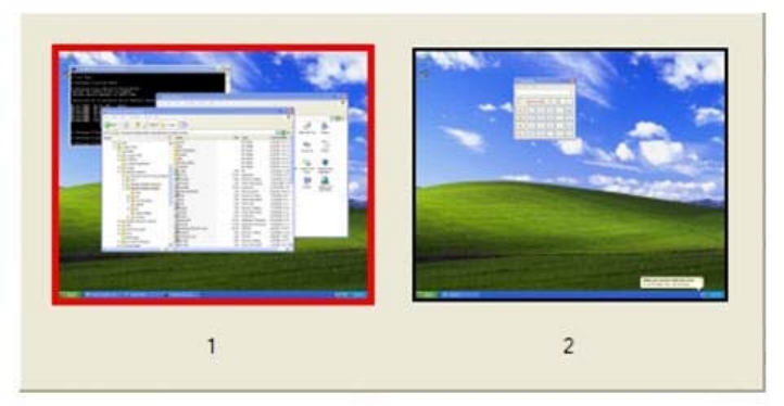
If Setup Mode is activated by the hotkey sequence (as opposed to the Setup Mode button), and you
have multiple Remote Display Windows on your computer, you can bring up the Remote Display
Window selection dialog to view a thumbnail image of each Remote Display Window.
Figure 7-3 Remote Display Window selection dialog
To display the selection dialog, press the TAB key while in Setup Mode—again, Setup Mode must have
been previously activated by the hotkey sequence. The selection dialog is displayed as long as the
initial Setup Mode hotkey (normally the Shift key) remains pressed. The currently-selected Remote
Display Window is highlighted with a red border.
The Remote Display Window selection dialog is only displayed in Directory Mode—this is the mode
that supports multiple Remote Display Windows. While the Remote Display Window selection dialog is
active, navigate between windows (thumbnails) by:
●Pressing TAB to select the next window.
●Clicking on the number displayed beneath the thumbnail.
●Clicking directly on a thumbnail.
●Double-clicking the mouse on a thumbnail (this will also immediately close the selection dialog).
When the initial Setup Mode hotkey is released, the selected Remote Display Window is brought
to the forefront and displayed.
Starting the Receiver in Directory Mode 173

8 RGS properties
RGS allows the user to specify many properties of the RGS connection, both on the Sender and
Receiver. By specifying properties, the user can modify RGS characteristics such as:
●Display of borders on the Remote Display Window
●Codec quality
●Audio quality
●Connection timeouts
This chapter describes each of the RGS properties, their default values, and how they can be changed.
Property syntax
Properties are name/value pairs, and can contain any non-whitespace characters except "=" and "#".
The property name and property value are separated by an "=". For example:
Rgreceiver.Network.Timeout.Warning=10000
In this example, the name of this property is Rgreceiver.Network.Timeout.Warning, and the value of the
property is 10000.
All RGS Receiver properties begin with "Rgreceiver" and all RGS Sender properties begin with
"Rgsender". Properties can contain values of the following types: string, int, bool, and int vector.
Properties of type bool are set to 1 or 0, representing true or false, respectively. A property can be set
to an empty value, such as:
Rgreceiver.Browser.Name=
Properties with empty values initialize as follows:
●If the value of the property is of type string, the value will be set to an empty string.
●If the value of the property is of type int vector or bool, the value will be set to 0.
Setting property values in a configuration file
RGS property values can be set in a configuration file. The RGS Receiver uses the rgreceiverconfig file
for its properties while the RGS Sender uses the file rgsenderconfig file for its properties. On Windows,
these files are located in the directory where the RGS Receiver and Sender are installed, typically:
174 Chapter 8 RGS properties

Receiver: C:\Program Files\Hewlett-Packard\Remote Graphics Receiver\rgreceiverconfig
Sender: C:\Program Files\Hewlett-Packard\Remote Graphics Sender\rgsenderconfig
On Linux, these files are located as follows:
Receiver: /etc/opt/hpremote/rgreceiver/rgreceiverconfig
Sender: /etc/opt/hpremote/rgsender/rgsenderconfig
The configuration files contain property name/value pairs, with only one property per line. Empty lines
(containing only whitespace characters) are ignored. The "#" character begins a comment on the line,
extending to the end of the line. If a property is listed more than once, the value of the last entry is
used.
NOTE: All properties in the configuration files are initially commented out with the “#” character. To
set a property in a configuration file, first delete the “#” character preceding the property name, and
then set the property to the desired value.
NOTE: RGS properties set in a configuration file do not take affect until the associated program is
restarted. For example, if the rgreceiverconfig file is changed, the Receiver should be restarted.
Likewise, if the rgsenderconfig file is changed, the Sender should be restarted.
Setting properties on the command line
Properties can also be set on the command line when the Receiver and Sender are started. Property
values entered on the command line override any properties set with other methods. All properties must
begin with a "-" on the command line to be recognized as a valid property. For example (on Linux):
rgreceiver.sh -Rgreceiver.Network.Timeout.Warning=10000
This command will start the RGS Receiver with the Rgreceiver.Network.Timeout.Warning property set to
10,000 milliseconds (10 seconds). If any property is set more than once on the command line, the
value of the last entry is used. No whitespace characters are allowed between the property name, the
"=" character, and the property value. For example:
rgreceiver.sh -Rgreceiver.IsSnap = 1
This property declaration is invalid because of the whitespace on both sides of the "=" character.
Properties of type int vector cannot be set on the command line.
CAUTION: If a property name is misspelled, no user notification is provided, and the misspelled
property will not take effect. If you specify a property in a configuration file or on a command line, and
it does not appear to take effect, first verify that the property name is spelled correctly and that upper/
lower case usage is correct.
Setting properties on the command line 175
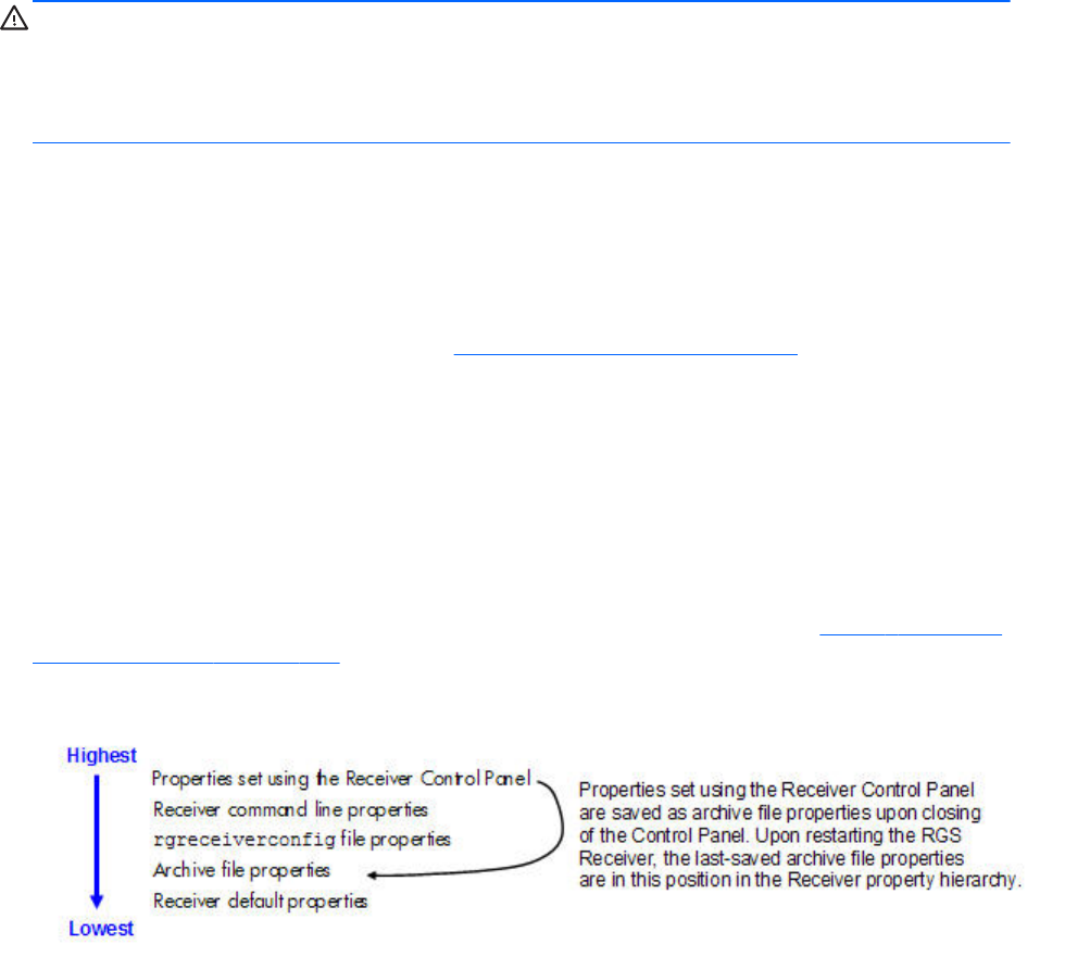
Authenticator properties
The following Sender and Receiver properties affect how the user authenticates an RGS connection:
Rgsender.LoggedInAuthenticators
Rgsender.LoggedOutAuthenticators
Rgreceiver.AuthenticatorId
Rgreceiver.AuthenticatorId.IsMutable
CAUTION: The authenticator properties are typically set by 3rd party software modules integrated
with RGS, and should not be changed. Changing these properties can have unexpected consequences,
including preventing you from establishing an RGS connection from the Receiver to the Sender.
Therefore, these properties are not listed nor described in the next two sections on user-settable RGS
Receiver and Sender properties.
RGS Receiver properties
This section describes the Receiver properties. RGS supports two types of Receiver properties:
●Per-Receiver properties—The per-Receiver properties affect all Remote Display Windows
generated by the Receiver. As noted in Many-to-one connection on page 18 a Receiver can
connect to multiple Remote Computers (and therefore generate multiple Remote Display Windows).
●Per-session properties—New in RGS 5.0, the per-session properties (also known as per-
connection properties) allow the user to specify the property values of each RGS connection. For
example, in a many-to-one configuration, per-session properties can be specified for each Remote
Display Window displayed by the Receiver.
Receiver property hierarchy
RGS supports the following hierarchy of methods to set the Receiver properties (see Figure 8-1 Receiver
property hierarchy on page 176).
Figure 8-1 Receiver property hierarchy
Properties set by methods higher on the list override properties set by methods lower on the list. For
example, a Receiver command line property can override a property specified in the rgreceiverconfig
file. Similarly, an archive file property (saved from the previous Receiver Control Panel session) can
override a Receiver default property.
176 Chapter 8 RGS properties

Restoring Receiver properties default values
Receiver property default values can be reset by uninstalling and reinstalling the Receiver.
Properties set using the Receiver Control Panel
The Receiver Control Panel enables the user to modify the values of many Receiver properties. For
example, as described in Remote Clipboard operation on page 159, the user can enable/disable
Remote Clipboard using the Receiver Control Panel. This affects the Rgreceiver.Clipboard.IsEnabled
property, as described in Receiver Remote Clipboard properties on page 193.
Receiver command line properties
See Setting properties on the command line on page 175.
rgreceiverconfig file properties
See Setting property values in a configuration file on page 174.
Archive file properties
When the Receiver is run, the user can change a number of properties using menus on the Receiver
Control Panel and the Remote Display Window. When the Receiver exits, it saves the state of any
properties that were changed by the user—these are known as archive file properties.
Receiver default properties
The Receiver has a set of default properties that are built into the Receiver. These are identical to the
property values in the Receiver configuration file (rgreceiverconfig) that is installed with the RGS
Receiver. However, as noted previously, the properties in both the Receiver and Sender configuration
files are initially commented out.
Receiver property groups
RGS supports the following groups of Receiver properties:
Per-receiver properties
●General properties group
◦Rgreceiver.IsBordersEnabled
◦Rgreceiver.IsSnapEnabled
◦Rgreceiver.IsAlwaysPromptCredentialsEnabled
◦Rgreceiver.Directory
◦Rgreceiver.MaxSenderListSize
◦Rgreceiver.IsMatchReceiverResolutionEnabled
RGS Receiver properties 177
◦Rgreceiver.IsMatchReceiverPhysicalDisplaysEnabled
◦Rgreceiver.RecentWindowPositions(deprecated)
◦Rgreceiver.ConnectionWarningColor
◦Rgreceiver.IsGlobalImageUpdateMutable(deprecated)
◦Rgreceiver.IsGlobalImageUpdateEnabled
◦Rgreceiver.MaxImageUpdateRequests
◦Rgreceiver.IsMouseSyncEnabled
◦Rgreceiver.IsMenubar.Enabled
◦Rgreceiver.IsAutoMenubarEnabled.IsMutable
◦Rgreceiver.IsAutoMenubarEnabled
◦Rgreceiver.IsDisconnectWarningEnabled
●Experience properties group
◦Rgreceiver.Experience.IsMutable
◦Rgreceiver.Experience.Mode
◦Rgreceiver.Experience.MinImageQuality
◦Rgreceiver.Experience.MinUpdateRate
●Browser properties group
◦Rgreceiver.Browser.IsMutable
◦Rgreceiver.Browser.Name
●Audio properties group
◦Rgreceiver.Audio.IsMutable
◦Rgreceiver.Audio.IsEnabled
◦Rgreceiver.Audio.Quality
◦Rgreceiver.Audio.IsFollowsFocusEnabled
◦Rgreceiver.Audio.IsInStereo
●Microphone property group
◦Rgreceiver.Mic.IsEnabled
178 Chapter 8 RGS properties
●USB properties group
◦Rgreceiver.Usb.IsMutable
◦Rgreceiver.Usb.ActiveSession
◦Rgreceiver.Usb.IsEnabled
●Network properties group
◦Rgreceiver.Network.Timeout.IsMutable
◦Rgreceiver.Network.Timeout.IsGuiEnabled
◦Rgreceiver.Network.Timeout.Warning
◦Rgreceiver.Network.Timeout.Error
◦Rgreceiver.Network.Timeout.Dialog
●Hotkey properties group
◦Rgreceiver.Hotkeys.IsMutable
◦Rgreceiver.Hotkeys.IsSetupModeEnabled
◦Rgreceiver.Hotkeys.SetupModeSequence
◦Rgreceiver.Hotkeys.IsSendCtrlAltEndAsCtrlAltDeleteEnabled
◦Rgreceiver.Hotkeys.IsSendFirstKeyInSequenceEnabled
◦Rgreceiver.Hotkeys.IsKeyRepeatEnabled
◦Rgreceiver.Hotkeys.IsCtrlAltDeletePassThroughEnabled
◦Rgreceiver.Hotkeys.IsGameModeEnabled
●Remote Clipboard properties group (see below for the per-session Remote Clipboard property)
◦Rgreceiver.Clipboard.IsMutable
◦Rgreceiver.Clipboard.IsEnabled
◦Rgreceiver.Clipboard.FilterString
●Logging properties group
◦Rgreceiver.Log.IsMutable
◦Rgreceiver.Log.IsFileLoggerEnabled
◦Rgreceiver.Log.Filename
RGS Receiver properties 179

◦Rgreceiver.Log.Level
◦Rgreceiver.Log.MaxFileSize
●Image codec properties group
◦Rgreceiver.ImageCodec.IsMutable
◦Rgreceiver.ImageCodec.Quality
◦Rgreceiver.ImageCodec.IsBoostEnabled
Per-session properties
●Auto Launch property set. (Windows only) See Auto Launch on page 123 for general details.
◦Rgreceiver.Session.<N>.IsConnectOnStartup
◦Rgreceiver.Session.<N>.Hostname
◦Rgreceiver.Session.<N>.Username
◦Rgreceiver.Session.<N>.Password
◦Rgreceiver.Session.<N>.PasswordFormat
●Remote Clipboard per-session property (see above for the per-Receiver Remote Clipboard
properties)
◦Rgreceiver.Session.<N>.Clipboard.IsEnabled
●Window placement and size group
◦Rgreceiver.Session.<N>.RemoteDisplayWindow.X
◦Rgreceiver.Session.<N>.RemoteDisplayWindow.Y
◦Rgreceiver.Session.<N>.VirtualDisplay.IsPreferredResolutionEnabled
◦Rgreceiver.Session.<N>.VirtualDisplay.PreferredResolutionHeight
◦Rgreceiver.Session.<N>.VirtualDisplay.PreferredResolutionWidth
With the exception of the general properties and the microphone property, all Receiver property groups
have an .IsMutable property (the group IsMutable property). The IsMutable property is always of type
bool. For example:
Rgreceiver.Audio.IsMutable=1
When the group IsMutable property is 1 (true), the user is allowed to interactively change the other
properties in the audio group—by using, for example, the Receiver Control Panel. When the group
IsMutable property is 0 (false), the user is prevented from interactively changing the other properties in
the group. All group IsMutuable properties have a default value of 1, which allows the user to
interactively change the other properties in the group.
With RGS 5.0, a new IsMutable feature was added. Each of the individual properties now has an
associated IsMutable Boolean property to control whether each individual property can be interactively
changed by the user—this is the individual IsMutable property. For example, the
180 Chapter 8 RGS properties
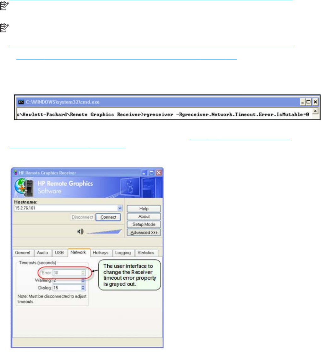
Rgreceiver.Network.Timeout.Error property now has the individual
Rgreceiver.Network.Timeout.Error.IsMutable property. If this RGS properties individual IsMutable
property is true, the user is allowed to interactively change the associated property, that is, the
Rgreceiver.Network.Timeout.Error property.
NOTE: For clarity, the individual IsMutable properties are not shown in the previous list; however,
they are included in the following detailed description of each property.
NOTE: In order for the user to be able to interactively change a property, the group IsMutable
property and the individual IsMutable property must both be 1 (true). If either IsMutable property is 0
(false), the user will not be able to interactively change the associated property.
In Figure 8-2 The Receiver timeout error IsMutable property is set to 0 on page 181, the Receiver is
started with the command line option –Rgreceiver.Network.Timeout.Error.IsMutable=0, which prevents
the user from changing the value of the network timeout error property.
Figure 8-2 The Receiver timeout error IsMutable property is set to 0
Because the Receiver timeout error property IsMutable property is 0, the Receiver timeout error property
cannot be changed by the user in the Receiver Control Panel (see Figure 8-3 The Receiver timeout error
property menu is grayed out on page 181).
Figure 8-3 The Receiver timeout error property menu is grayed out
RGS Receiver properties 181

Receiver general properties
The general properties are listed below. After each property, the default value is listed in parenthesis.
Rgreceiver.IsBordersEnabled=bool (default=1)
Rgreceiver.IsBordersEnabled.IsMutable=bool (default=1)
If set to 1, the borders on the Remote Display Window will be enabled (displayed). If set to 0, the
borders will be removed creating a borderless windows to display the Remote Computer desktop. The
default value is 1— the borders are enabled.
Rgreceiver.IsSnapEnabled=bool (1)
Rgreceiver.IsSnapEnabled.IsMutable=bool (1)
If set to 1, as the Remote Display Window is being positioned on the display, the window will snap to
the edge of the screen when the top edge of the window moves within 10 pixels of the top of the
display, or when the left edge of the window moves within 10 pixels of the left edge of the display. The
default value is 1—snap is enabled.
Rgreceiver.IsAlwaysPromptCredentialsEnabled=bool (0)
Rgreceiver.IsAlwaysPromptCredentialsEnabled.IsMutable=bool (1)
If set to 1, when connecting to an RGS Sender, the user will always be prompted for the domain,
username and password. There will be no attempt to automatically verify the user credentials. The
default value is 0—prompting for credentials is off.
Rgreceiver.Directory=string (directory.txt)
Rgreceiver.Directory.IsMutable=bool (1)
Used in Directory Mode to set the name and location of the file that lists the Remote Computers
assigned to the current user. The default value is "directory.txt".
Rgreceiver.MaxSenderListSize=int (5)
Rgreceiver.MaxSenderListSize.IsMutable=bool (1)
In Normal Mode, the Receiver keeps a list of the Senders that it has most recently connected to. Figure
8-4 The Receiver maintains a list of the most recently connected Senders. on page 183 shows the
Receiver Control Panel dialog that this property applies to. This property specifies the maximum number
of Remote Computers the Receiver will keep on its list—in Figure 8-4 The Receiver maintains a list of the
most recently connected Senders. on page 183, two Remote Computers (Senders) are on the list. The
182 Chapter 8 RGS properties
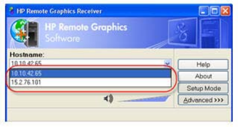
Receiver will keep the most recently connected Remote Computers on its list, up to the maximum number
specified by this property. Minimum useful value is 1.
Figure 8-4 The Receiver maintains a list of the most recently connected Senders.
Rgreceiver.IsMatchReceiverResolutionEnabled=bool (0)
Rgreceiver.IsMatchReceiverResolutionEnabled.IsMutable=bool (1)
If this property is enabled, the Local Computer (Receiver) will attempt to set the resolution of the Remote
Computer to the same full-screen resolution of the Local Computer. If the Local Computer display
resolution is not supported by the Remote Computer, the connection occurs at the existing Remote
Computer (Sender) resolution, and a warning dialog is issued to the user. The original (pre-
modification) Remote Computer display resolution is restored when the RGS connection is terminated.
Rgreceiver.IsMatchReceiverPhysicalDisplaysEnabled=bool (0)
Rgreceiver.IsMatchReceiverPhysicalDisplaysEnabled.IsMutable=bool (1)
If the following conditions are met:
1. This property is enabled.
2. Rgreceiver.IsMatchReceiverResolutionEnabled is enabled (see above property).
3. Rgreceiver.Session.<N>.VirtualDisplay.IsPreferredResolutionEnabled is
disabled.
Then the Receiver will try to set the layout of the Remote Computer (Sender) physical displays to have
the same display layout and resolution as the Receiver displays. If the Sender is unable to match the
layout and resolution of the Receiver physical displays, the Receiver will try to just match the Receiver
display resolution.
For example, if the Receiver has two physical displays in a 1x2 layout and a overall virtual display
resolution of 2560x1024 (1280x1024x2), the Receiver will try to set the Sender to the same layout
and resolution. If that fails, the Receiver will try to set a single physical display resolution of
2560x1024. If that fails, an error is reported.
If the following conditions are met:
1. This property is enabled.
2. Rgreceiver.Session.<N>.VirtualDisplay.IsPreferredResolutionEnabled is
enabled.
RGS Receiver properties 183

NOTE: As noted earlier,
Rgreceiver.Session.<N>.VirtualDisplay.IsPreferredResolutionEnabled takes
precedence over Rgreceiver.IsMatchReceiverResolutionEnabled. Therefore, if the former
property is enabled (as listed in paragraph 2 above), the latter property is a “don’t care”, and its
setting is ignored.
If the above conditions are met, the Receiver will determine the physical displays that are contained
within the Receiver Remote Display Window specified by these properties:
●Rgreceiver.Session.<N>.RemoteDisplayWindow.X
●Rgreceiver.Session.<N>.RemoteDisplayWindow.Y
●Rgreceiver.Session.<N>.VirtualDisplay.PreferredResolutionWidth
●Rgreceiver.Session.<N>.VirtualDisplay.PreferredResolutionHeight.
The Receiver will try to set the layout of the Remote Computer (Sender) physical displays to match the
physical displays contained in this window. For example, if the Receiver has the following:
●Two physical displays in a 1x2 layout
●An overall virtual display resolution of 2560x1024 (1280x1024x2)
●Rgreceiver.Session.<N>.RemoteDisplayWindow.X = 1280
●Rgreceiver.Session.<N>.RemoteDisplayWindow.Y = 0
●Rgreceiver.Session.<N>.VirtualDisplay.PreferredResolutionWidth = 1280
●Rgreceiver.Session.<N>.VirtualDisplay.PreferredResolutionHeight = 1024
Then the Receiver will determine that one physical display with a resolution of 1280x1024 is contained
within the window. The Receiver will try to set the layout of the Remote Computer Sender to a single
physical display and a resolution of 1280x1024.
If the following conditions are met:
1. This property is enabled.
2. Rgreceiver.IsMatchReceiverResolutionEnabled is disabled.
3. Rgreceiver.Session.<N>.VirtualDisplay.IsPreferredResolutionEnabled is
disabled.
Then this property has no affect.
NOTE: The following property, while supported, has been deprecated. HP recommends using the
per-session Remote Display Window X and Y positioning properties described in Window placement
and size properties on page 197.
Rgreceiver.RecentWindowPositions=int vector (10 10)
Rgreceiver.RecentWindowPositions.IsMutable=bool (1)
184 Chapter 8 RGS properties

This property can be used to set the positions of the Remote Display Windows. The position of each
Remote Display Window is controlled by an (xpos,ypox) 2-tuple. The following example contains two 2-
tuples, one for each of two Remote Display Windows:
Rgreceiver.RecentWindowPositions=0 0 1280 0
This property will set the coordinates (upper left corner) of the first Remote Display Window to (0, 0)
and the second Remote Display Window to (1280, 0). In this example, if each Remote Display
Window is 1280x1024, the first window will be positioned on the left of the Local Computer display,
and the second window will be placed immediately adjacent, and to the right, of the first window,
making them appear as one large 2560x1024 display.
Rgreceiver.ConnectionWarningColor=string (0x80b40000)
Rgreceiver.ConnectionWarningColor.IsMutable=bool (1)
The ConnectionWarningColor property sets the warning color that overlays the Remote Display
Window when the RGS Receiver detects a network disruption. The warning color is a four byte number,
with each byte providing the following information:
●alpha byte—specifies the transparency value of the warning color that overlays the Remote
Display Window
●red byte—specifies the red component of the warning color
●green byte—specifies the green component of the warning color
●blue byte—specifies the blue component of the warning color
An alpha value of 0x00 will be totally transparent, meaning that no warning color will be visible to the
user. An alpha value of 0xFF will be totally opaque, completely covering the image in the Remote
Display Window with the warning color.
The default value of the warning color is 0x80b40000, representing the following:
●The alpha component is 0x80 (128 decimal. This is 50% transparent.
●The red component is 0xb4 (180 decimal). This is about 70% of full red (0xFF).
●The green component is 0x00. There is no green component.
●The blue component is 0x00. There is no blue component.
NOTE: The following property, while supported, has been deprecated. HP recommends that the
subsequent properties, Rgreceiver.IsGlobalImageUpdateEnabled and its associated IsMutable property,
be used instead.
Rgreceiver.IsGlobalImageUpdateMutable=bool (1)
If set to 1, the user will be able to modify the Enable global image updates checkbox in the
Receiver Control Panel. If set to 0, the user will be unable to modify the checkbox. This property can be
used to permanently enable or disable global image updates in the Receiver. The default value is 1—
global image updates can be configured by the user.
Rgreceiver.IsGlobalImageUpdateEnabled=bool (0)
RGS Receiver properties 185
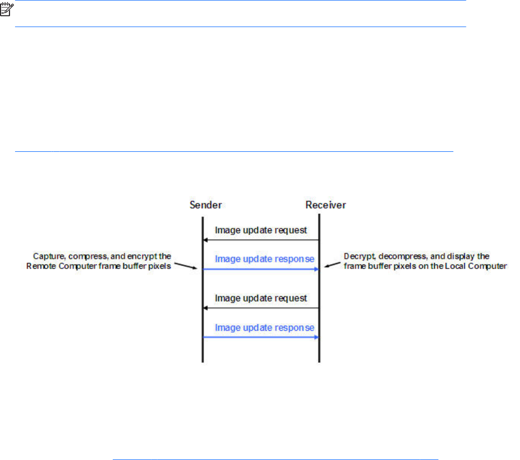
Rgreceiver.IsGlobalImageUpdateEnabled.IsMutable=bool (1)
If set to 1, the Receiver updates the area of the screen with the extents of all the areas of the screen
that have changed. If set to 0, the Receiver limits updates of the screen to just the areas that have
changed, using individual update rectangles.
If image updates in the Remote Display Window show image tearing, setting the value to 1 (enabling
global image updates) may reduce the tearing. Tearing usually occurs on large images that are
updated quite frequently, such as a 3D object being rotated in a large window. Setting the property
value to 0 (disabling global image updates) is usually best for large Remote Display Windows (5120 x
1024 resolution) that display mostly text based applications. The default value is 0—global image
updates are disabled.
NOTE: The following property was added in the RGS 5.1.3 release to enable RGS performance
optimization in high-latency network environments.
Rgreceiver.MaxImageUpdateRequests=int (4)
Rgreceiver.MaxImageUpdateRequests.IsMutable=bool (1)
This property controls the maximum number of outstanding image update requests between the RGS
Receiver (requestor) and the RGS Sender (responder). Prior to RGS 5.1.3, the number of outstanding
image update requests was preset to 1. This meant that the Receiver, after issuing an image update
request, would wait for the image update response to be completed before issuing another request.
Figure 8-5 Prior to RGS 5.1.3, only one image update would be in-process at any time on page 186
shows the sequence chart for this.
Figure 8-5 Prior to RGS 5.1.3, only one image update would be in-process at any time
The Rgreceiver.MaxImageUpdateRequests property was added to enable performance
optimization in high-latency network environments. For example, setting this property to 2 will allow the
Receiver to issue a second image update request to the Sender prior to receiving the previous image
update response. This allows the Sender and Receiver to operate more in parallel—but at the potential
expense of increased network bandwidth consumption.
The sequence chart in Figure 8-6 Sequence chart for the default property value of 4 on page 187
shows operation for the default property value of 4. In this case, the Receiver can have up to 4 image
update requests outstanding at any given time. When image update response #1 is received (meaning
186 Chapter 8 RGS properties
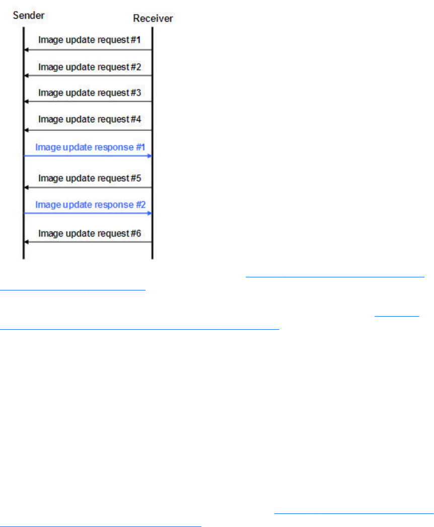
that there are now 3 outstanding image update requests), the Receiver can issue image update request
#5 (again, up to a maximum of 4 outstanding image update requests at any given time).
Figure 8-6 Sequence chart for the default property value of 4
The sequence can vary considerably from that shown in Figure 8-6 Sequence chart for the default
property value of 4 on page 187. For example, image update response #1 might be received prior to
issuance of image update request #4. Also, TCP will temporarily block the Sender from sending further
data if the Receiver network buffer becomes full. Nonetheless, the sequence shown in Figure 8-6
Sequence chart for the default property value of 4 on page 187 serves to parallelize local display
updates that otherwise would occur serially.
The default property value of 4 was determined empirically as a good compromise for both low and
high-latency network environments. Larger numbers of outstanding requests may be beneficial in some
cases depending on the number and types of updates occurring. In high-latency network environments,
HP recommends that you characterize RGS performance for different values of the
Rgreceiver.MaxImageUpdateRequests property.
Rgreceiver.IsMouseSyncEnabled=bool (1)
Rgreceiver.IsMouseSyncEnabled.IsMutable=bool (1)
This property was added with RGS 5.2.5, and allows the RGS Receiver to track an instantaneous
programmatic move of the mouse on the sender. This type of move is occasionally seen when a
window is moved or resized. It is also seen when the Snap To box is checked in the Mouse Properties
Pointer Options dialog on the Windows Sender computer (see Figure 8-7 Pointer Options tab in the
Sender Mouse Properties dialog on page 188). Checking of the Snap To box causes the Sender
mouse pointer to be automatically moved to the default button in a dialog box.
RGS Receiver properties 187
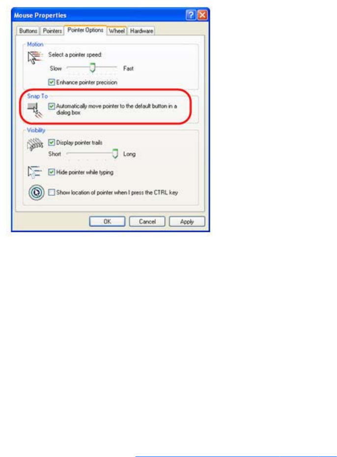
Figure 8-7 Pointer Options tab in the Sender Mouse Properties dialog
When the Rgreceiver.IsMouseSyncEnabled property is set to 1 on the Receiver and when an automatic
snap to action occurs on the Sender, the snap to action will be communicated from the Sender to the
Receiver; the RGS Receiver will then move the mouse cursor to reflect the cursor position in the Sender
dialog box where the snap to action occurred. If this property is set to 0, snap to actions on the Sender
will not be reflected on the Receiver.
This features requires that the Windows or Linux Receiver be version 5.2.5 or later. This feature is
supported on the Windows Sender version 5.2.5 or later and on the Linux Sender version 5.4.5 or
later.
Rgreceiver.IsMenubarEnabled=bool (1)
This property was added with RGS 5.4.0 and allows the user to disable the Remote Display Window
Toolbar functionality. When the Rgreceiver.IsMenubarEnabled property is set to 1 the user will be able
to display the Remote Display Window Toolbar by pressing the Hotkey-H. When the
Rgreceiver.IsMenubarEnabled property is set to 0 the user will be unable to access the Remote Display
Window Toolbar by pressing Hotkey-H. In other words, when the property is disabled the Hotkey-H
command is turned off. See the Remote Display Window Toolbar on page 106 section for more details.
Rgreceiver.IsAutoMenubarEnabled=bool (1)
This property was added with RGS 5.4.5 and controls the default behavior of the Auto show toolbar
functionality. Rgreceiver.IsMenubarEnabled must be set to 1 to allow
Rgreceiver.IsAutoMenubarEnabled to function. When the Rgreceiver.IsAutoMenubarEnabled property is
set to 1, the default, the Auto show toolbar feature is on at startup. When the
Rgreceiver.IsAutoMenubarEnabled property is set to 0, the Auto show toolbar feature is off at startup.
Rgreceiver.IsAutoMenubarEnabled.IsMutable=bool (1)
This property was added with RGS 5.4.5 and controls the user's ability to enable or disable the Auto
show toolbar functionality. When the Rgreceiver.IsAutoMenubarEnabled.IsMutable property is set to 1,
the user can turn Auto show toolbar feature on and off in the Receivers Advanced > General tab.
188 Chapter 8 RGS properties
When the Rgreceiver.IsAutoMenubarEnabled.IsMutable property is set to 0, the user cannot turn Auto
show toolbar feature on in the Receivers Advanced > General tab.
Rgreceiver.IsDisconnectWarningEnabled=bool (0)
This property was added with RGS 5.4.5 and allows the user to enable a warning dialog when closing
the RGS window while RGS is still connected. This warning dialog will warn the user that disconnecting
from RGS while they are still logged in will not log the user out of the remote system.
Receiver experience properties
Rgreceiver.Experience.IsMutable=bool (1)
When set to 1, the default, the user can turn this feature on and off in the Receivers Advanced >
General tab, Experience section. Setting to 0 disables the user's ability to turn the feature on and
off.
Rgreceiver.Experience.Mode=FixedImageQuality | AdjustImageQuality
This property allows the user to set the startup behavior for the interactive experience controls.
FixedImageQuality is the default. AdjustImageQuality will cause RGS to use the settings for Minimum
image quality and Minimum update rate and adjust the image if needed.
Rgreceiver.Experience.MinImageQuality=int (20)
Controls the startup value for image quality if AdjustImageQuality is enabled. The minimum image
quality specifies the lowest quality level that will be used during the automatic adjustment. The minimum
image quality is absolute - the system will not lower quality below the specified value. Values are from
0 to 100 with a default of 20.
Rgreceiver.Experience.MinUpdateRate=int (30)
Controls the startup value for minimum update rate if AdjustImageQuality is enabled. The minimum
update rate controls how aggressively the image quality is reduced. Specifying a minimum update rate
of 30 will drive the most aggressive quality reduction. The minimum update rate is a target. The
available bandwidth may be too low to maintain the target rate. Values are from 0 to 30 with a default
of 30.
Receiver browser properties
Rgreceiver.Browser.IsMutable=bool (1)
This property only applies to the Linux RGS Receiver. If set to 1, the name of the browser used to
display online help can be changed by the user in the Receiver Control panel. If set to 0, the name of
the browser cannot be changed by the user.
Rgreceiver.Browser.Name=string (mozilla)
Rgreceiver.Browser.Name.IsMutable=bool (1)
This property only applies to the Linux RGS Receiver, and can be used to set the name of the browser to
display online help. For example, setting Rgreceiver.Browser.Name=mozilla will start the Mozilla
browser when the Help button is clicked in the Receiver Control Panel.
RGS Receiver properties 189
For the Windows Receiver, the Help system is based on a CHM file.
Receiver audio properties
Rgreceiver.Audio.IsMutable=bool (1)
If set to 1, the user will be able to modify all audio controls in the RGS Receiver. If set to 0, none of the
audio controls can be modified by the user. The default value is 1—the audio controls can be modified
by the user.
Rgreceiver.Audio.IsEnabled=bool (1)
Rgreceiver.Audio.IsEnabled.IsMutable=bool (1)
If set to 1, the RGS audio subsystem will be enabled. If set to 0, RGS audio will be disabled and no
network bandwidth will be consumed for remote audio. The default value is 1—audio is enabled.
Rgreceiver.Audio.Quality=int (1)
Rgreceiver.Audio.Quality.IsMutable=bool (1)
The audio quality property can be set to low (0), medium (1), or high (2) quality. This property is used
to adjust the sample rate of the streaming audio. Less information is sent over the network if the sample
rate is lower—and, therefore, the less network bandwidth that is consumed. The default value is 1—
medium audio quality.
Rgreceiver.Audio.IsFollowsFocusEnabled=bool (0)
Rgreceiver.Audio.IsFollowsFocusEnabled.IsMutable=bool (1)
If set to 1, enables only the audio stream associated with the Remote Display Window that currently
has the keyboard focus. The audio stream from all other active connections is disabled. Setting the
property to 0 combines the audio from all active connections into a single stream. The default value is 0
—combine audio from all active connections, and play in a single stream.
Rgreceiver.Audio.IsInStereo=bool (1)
Rgreceiver.Audio.IsInStereo.IsMutable=bool (1)
If set to 1, stereo is enabled, and both the left and right channels are transmitted. The highest quality
audio (2) with stereo enabled is equivalent to CD quality audio but consumes more network bandwidth.
The default value is 1—stereo is enabled.
Receiver microphone property
Rgreceiver.Mic.IsEnabled=bool (0)
Rgreceiver.Mic.IsEnabled.IsMutable=bool (1)
This property is new with the RGS 5.1.3 release. If set to 1, remote microphone is enabled (on/
unmuted). The default value is 0—remote microphone is disabled (off/muted).
190 Chapter 8 RGS properties

Receiver USB properties
Rgreceiver.Usb.IsMutable=bool (1)
If set to 1, the user can modify all USB controls in the Receiver Control Panel. If set to 0, none of the
USB controls can be changed by the user. This property can be used to permanently enable or disable
remote USB before the RGS Receiver is started. The default value is 1—the user can modify all USB
controls.
Rgreceiver.Usb.IsEnabled=bool (1)
Rgreceiver.Usb.IsEnabled.IsMutable=bool (1)
If set to 1, remote USB will be enabled. If set to 0, remote USB will be disabled. The default value is 1
—remote USB is enabled.
Rgreceiver.Usb.ActiveSession=int (0)
Rgreceiver.Usb.ActiveSession.IsMutable=bool (1)
When the Receiver is in Directory Mode, the Local Computer can connect to one or more Remote
Computers. This property specifies the Remote Computer that the local USB devices are attached to. To
have all local USB devices attached to the first Remote Computer, use value zero. To have all local USB
devices attached to the second Remote Computer, use value one, and so on. The default value is 0—
the local USB devices are attached to the first Remote Computer.
The local USB devices can only be attached to one Remote Computer at a time. To change which
Remote Computer the local USB devices are attached to, all Remote Computers must be disconnected.
Then enter a new value for this property, and reconnect to all Remote Computers.
Receiver network properties
Rgreceiver.Network.Timeout.IsMutable=bool
If set to 1, the user can modify all network timeout values in the RGS Receiver Control Panel. If set to 0,
the user cannot modify the values. This property can be used to permanently set network timeouts
before the RGS Receiver is started. The default value is 1—timeout values are changeable by the user.
Rgreceiver.Network.Timeout.IsGuiEnabled=bool (1)
This property was added with RGS 5.4.0 and allows the user to disable a visual notification when the
network has timed out. When the Rgreceiver.Network.Timeout.IsGuiEnabled property is set to 1 the
network timeout is shown. When the Rgreceiver.Network.Timeout.IsGuiEnabled property is set to 0 the
visual network timeout notification is not shown. See Receiver network timeouts on page 149 for more
details.
Rgreceiver.Network.Timeout.Warning=int (2000)
Rgreceiver.Network.Timeout.Warning.IsMutable=int (1)
The timeout in milliseconds used to detect and notify the user of a network disruption. The default value
is 2,000 milliseconds (2 seconds).
Rgreceiver.Network.Timeout.Error=int (30000)
RGS Receiver properties 191

Rgreceiver.Network.Timeout.Error.IsMutable=int (1)
The timeout in milliseconds used to detect and disconnect an inactive connection. The default value is
30,000 milliseconds (30 seconds).
Rgreceiver.Network.Timeout.Dialog=int (15000)
Rgreceiver.Network.Timeout.Dialog.IsMutable=bool (1)
This property specifies the timeout in milliseconds used to display, and wait on responses from, input
dialogs, such as the authorization dialog and the PAM authentication dialog. The default value is
15,000 milliseconds (15 seconds).
Receiver hotkey properties
Rgreceiver.Hotkeys.IsMutable=bool (1)
If set to 1, all Hotkey settings in the Receiver Control Panel can be changed by the user. If set to 0,
none of the hotkey settings can be changed by the user. This property can be used to permanently
enable or disable hotkey settings before the RGS Receiver is started. The default value is 1—hotkeys
can be changed by the user.
Rgreceiver.Hotkeys.IsSetupModeEnabled=bool (1)
This property was added with RGS 5.4.0 and allows the user to completely disable all hotkeys. When
the Rgreceiver.Hotkeys.IsSetupModeEnabled property is set to 1 the hotkeys will work as normal. When
the Rgreceiver.Hotkeys.IsSetupModeEnabled property is set to 0 all hotkeys are disabled. In other
words pressing the hotkey sequence will not do anything. See Hotkeys on page 156 for more details.
Rgreceiver.Hotkeys.SetupModeSequence=string (“Shift Down, Space Down,
Space up”)
Rgreceiver.Hotkeys.SetupModeSequence.IsMutable=bool (1)
Defines the Setup Mode hotkey sequence. The sequence may only consist of Ctrl, Alt, Shift and Space
keys. The sequence must also start with either a Ctrl, Alt or Shift key. The first key must also be held
down through the entire hotkey sequence. The default value is "Shift Down, Space Down, Space Up".
Rgreceiver.Hotkeys.IsSendCtrlAltEndAsCtrlAltDeleteEnabled=bool (1)
Rgreceiver.Hotkeys.IsSendCtrlAltEndAsCtrlAltDeleteEnabled.IsMutable=bool
(1)
When enabled a Ctrl-Alt-End key sequence in the Remote Display Window is sent to the Remote
Computer as a Ctrl-Alt-Del key sequence. The default value is 1—send a Ctrl-Alt-Del when the user
enters Ctrl-Alt-End.
Rgreceiver.Hotkeys.IsSendFirstKeyInSequenceEnabled=bool (0)
Rgreceiver.Hotkeys.IsSendFirstKeyInSequenceEnabled.IsMutable=bool (1)
When enabled, the first key in the hotkey sequence is sent to the Remote Computer. The default value is
0—do not send the first key in the hotkey sequence.
Rgreceiver.Hotkeys.IsKeyRepeatEnabled=bool (0)
192 Chapter 8 RGS properties

Rgreceiver.Hotkeys.IsKeyRepeatEnabled.IsMutable=bool (1)
The hotkey sequence is very particular (for example, shift down, space down, space up). The Windows
operating system injects key repeats as repeating down events, for example, shift down, shift down, …,
shift up. By default, the Receiver ignores these key repeats in the hotkey state machine. The Local
Computer may be set up to process key repeats in the hotkey state machine, which may be necessary
for certain types of applications. Note that, if this setting is enabled, the sequence shift down, shift
down, space down, space up will not trigger setup mode, so the sequence must be typed faster if this
setting is enabled.
Rgreceiver.Hotkeys.IsCtrlAltDeletePassThroughEnabled=bool (0)
Rgreceiver.Hotkeys.IsCtrlAltDeletePassThroughEnabled.IsMutable=bool (1)
When a Windows Local Computer detects a Ctrl-Alt-Delete key sequence, it does not send the sequence
to the Remote Computer—only the Local Computer processes the key sequence. Setting this property to
1 will result in both the Remote and Local Computers processing the key sequence. Note that some third
party software tools or OS configurations may be available to disable the Ctrl-Alt-Delete sequence on
the Local Computer.
Rgreceiver.Hotkeys.IsGameModeEnabled=bool (1)
This property was added with RGS 5.4.0 and allows the user to disable the Game Mode functionality.
When the Rgreceiver.Hotkeys.IsGameModeEnabled property is set to 1 the Game Mode functionality is
available. When the Rgreceiver.Hotkeys.IsGameModeEnabled property is set to 0 the Game Mode
functionality is disabled. In other words, pressing Hotkey-G has no affect. See Game Mode
on page 124 for more details.
Receiver Remote Clipboard properties
NOTE: The Remote Clipboard functionality and properties were added with the RGS 5.1.3 release.
At the RGS 5.2.0 release, the properties Rgreceiver.Session.<N>.Clipboard.IsEnabled and
Rgreceiver.Clipboard.FilterString were added.
Rgreceiver.Clipboard.IsMutable=bool (1)
If set to 1, the Remote Clipboard setting in the Receiver Control Panel can be changed by the user. If
set to 0, the user cannot change the Remote Clipboard settings. The default value is 1—the Remote
Clipboard setting can be changed by the user.
Rgreceiver.Clipboard.IsEnabled=bool (1)
Rgreceiver.Clipboard.IsEnabled.IsMutable=bool (1)
This is a per-receiver property. If set to 1, the local user can use Remote Clipboard. If set to 0, the local
user cannot use Remote Clipboard. The default value is 1—Remote Clipboard is enabled.
Rgreceiver.Session.<N>.Clipboard.IsEnabled=bool (1)
This is a per-session property. If set to 1, Remote Clipboard is enabled for the session N Remote
Display Window. In order for Remote Clipboard operation to be enabled for session N, the per-
receiver property Rgreceiver.Clipboard.IsEnabled must also be 1. The default value for both properties
(per-receiver and per-session) is 1—Remote Clipboard is enabled.
RGS Receiver properties 193

Rgreceiver.Clipboard.FilterString=string(see below for the default value)
NOTE: This property is for advanced users only. The property string should be changed from its
default value only if Remote Clipboard doesn’t support the clipboard format required by your
application. For more information on clipboard formats, see the Microsoft Developer Network article
Clipboard Formats at http://msdn2.microsoft.com/en-us/library/ms649013.aspx.
This property contains a list of clipboard formats allowed to be transferred using Remote Clipboard.
Therefore, this property is a keep filter, not a reject filter. The string is a regular expression, and is used
by both the Remote and Local Computers. The rgreceiverconfig file contains the following entry for this
property, which indicates the default clipboard formats supported by RGS:
# Rgreceiver.Clipboard.FilterString="|1|2|7|8|13|16|17|Ole Private Data|
Object Descriptor |Link Source Descriptor|HTML Format|Rich Text Format|
XML Spreadsheet|"
The default clipboard formats are:
●1 (CF_TEXT)—Text format. Each line ends with a carriage return/linefeed (CR-LF) combination. A
null character signals the end of the data. Use this format for ANSI text.
●2 (CF_BITMAP)—Bitmap format.
●7 (CF_OEMTEXT)—Text format containing characters in the OEM character set. Each line ends
with a carriage return/linefeed (CR-LF) combination. A null character signals the end of the data.
●8 (CF_DIB)—A memory object containing a BITMAPINFO structure followed by the bitmap bits.
●13 (CF_UNICODETEXT)—Unicode text format. Each line ends with a carriage return/linefeed (CR-
LF) combination. A null character signals the end of the data.
●16 (CF_LOCALE)—Locale identifier associated with text in the clipboard
●17 (DIBV5)—Bitmap color space and bitmap data
●Ole Private Data—A private application format understood only by the application offering the
format.
●Object Descriptor—OLE2 object descriptor
●Link Source Descriptor—Link to OLE2 object
●HTML Format—Text is in Hypertext Markup Language format
●Rich Text Format—A text format that includes special formatting features, such as bold, italics, and
centering.
●XML Spreadsheet—A format created by Microsoft to allow Excel spreadsheets to be saved in XML
(Extensible Markup Language) format. This format is supported by other applications as well.
Receiver logging properties
Rgreceiver.Log.IsMutable=bool(1)
If set to 1, the logging settings in the Receiver Control Panel can be changed by the user. If set to 0, the
user will not be able to change any of the logging settings. This property can be used to permanently
194 Chapter 8 RGS properties
enable or disable logging settings before the RGS Receiver is started. The default value is 1—logging
settings can be changed.
Rgreceiver.Log.IsFileLoggerEnabled=bool (1)
Rgreceiver.Log.IsFileLoggerEnabled.IsMutable=bool (1)
If set to 1, logging output from the RGS Receiver will be sent to a file. The default value is 1 —log to a
file.
Rgreceiver.Log.Filename=string (rg.log)
Rgreceiver.Log.Filename.IsMutable=bool (1)
This property specifies the path to the log file, and is only used if RgReceiver.Log.IsFileLoggerEnabled is
set to 1. The default path on Windows is located in the directory where the RGS Receiver is installed,
normally C:/Program Files/Hewlett-Packard/Remote Graphics Receiver/rg.log. The default path on
Linux is $HOME/.hpremote/rgreceiver/rg.log.
Rgreceiver.Log.Level=string ("INFO")
Rgreceiver.Log.Level.IsMutable=bool (1)
RGS supports five logging levels: DEBUG, INFO, WARN, ERROR, and FATAL. If DEBUG is chosen, all
level of output from DEBUG to FATAL will be output to the log file. If WARN level is chosen, all levels
from WARN to FATAL will be output. The default value is INFO—all DEBUG output is turned off.
Rgreceiver.Log.MaxFileSize=int (1024)
Rgreceiver.Log.MaxFileSize.IsMutable=bool (1)
This sets the maximum size of the log file in kilobytes (Kbytes). The default maximum size is 1,024
Kbytes.
Receiver image codec properties
Rgreceiver.ImageCodec.IsMutable=bool (1)
If set to 1, the local user can adjust the image quality using the Remote Display Window Toolbar. If set
to 0, the user cannot change the image quality. This property and the following property can be used
to permanently set the image quality before the Receiver is started. The default value is 1—the image
quality can be adjusted by user.
Rgreceiver.ImageCodec.Quality=int (65)
Rgreceiver.ImageCodec.Quality.IsMutable=bool (1)
This property sets the image quality in the Remote Display Window, and can be set to a value from 0
to 100. A value of 100 is the highest quality image while 0 is the lowest image quality. Under most
circumstances, the default value of 65 will be sufficient. Lower values of
Rgreceiver.ImageCodec.Quality will typically reduce RGS bandwidth requirements on the network. If
the Sender property, Rgsender.ImageCodec.Preferred, is set to Rgsender.ImageCodec.Preferred=JPEG-
LS, the Rgreceiver.ImageCodec.Quality property is ignored.
RGS Receiver properties 195

NOTE: Even with an image quality of 100, RGS still performs image compression to reduce the
network bandwidth requirements. While the image on the Receiver will usually appear visually lossless
to the user at an image quality of 100, the actual image data sent over the network from the Sender to
the Receiver will be “lossy” to a limited extent. The exception is the Sender codec JPEG-LS which is
mathematically lossless. See Sender general properties on page 200 for more information.
Rgreceiver.ImageCodec.IsBoostEnabled=bool (1)
Rgreceiver.ImageCodec.IsBoostEnabled.IsMutable=bool (1)
This property was added beginning with RGS 5.2.6, and requires that both the RGS Sender and
Receiver be version 5.2.6 or later. Setting the property to 1 will improve (boost) image quality for
certain types of images, namely those images containing significant amounts of text or lines. Because of
the high contrast ratio between adjacent pixels, such images often don’t compress well. When this
property is set to 1, such high contrast cases will be compressed in a manner to better preserve their
visual quality, but at the possible expense of higher network bandwidth and/or lower image update
rates. The default value is 1—image quality will be improved.
This property affects the setting of the Boost checkbox as described in Remote Display Window Toolbar
on page 106.
Auto Launch session properties
These properties are per-session (per-connection) properties. If, for example, the user wants to auto
connect to various Remote Computers, these properties can be used to specify the properties of each of
the various Remote Display Windows on the Local Computer. A .rgreceiver file is required for each
Remote Computer. These properties contain the parameter <N> which currently must be set to 0 in
the .rgreceiver file. The .rgreceiver file may also contain Window size and placement properties. For
example, the name of the Sender system is specified by the property Rgreceiver.Session.0.Hostname.
See Auto Launch on page 123 for general details. Only a single instance of the RGS Receiver is
currently supported. Any existing connection to a Remote Computer must be closed prior to Auto
Launching another connection. To connect to multiple Remote Computers simultaneously, see Using
Directory Mode on page 170 .
NOTE: These properties are used only on Windows, control automatic connection to the Remote
Computer and do not have default settings.
Rgreceiver.Session.<N>.IsConnectOnStartup=bool
This property specifies whether the Receiver should automatically try to connect on start-up via an
associated file event.
Rgreceiver.Session.<N>.Hostname=string
The hostname or IP address as a utf8 encoded string, to use if automatically connecting on start-up.
Rgreceiver.Session.<N>.Username=string
The username as a utf8 encoded string, to use if automatically connecting on start-up.
Rgreceiver.Session.<N>.Password=string
The password as a utf8 encoded string, to use if automatically connecting on start-up.
196 Chapter 8 RGS properties

Rgreceiver.Session.<N>.PasswordFormat=Encrypted | Clear | XOR
The format of the password. RGS supports three formats Encrypted, Clear or XOR. Encrypted is only
supported on Windows and is the hexadecimal string representation of a password encrypted using the
Windows command CryptProtectData. Clear is the password as clear text. XOR is the hexadecimal
string representation of a password XORed against the value 129. See http://msdn.microsoft.com/en-
us/library/aa380261(VS.85).aspx for more information on implementing the Windows API function
CryptProtectData.
Window placement and size properties
As described previously, these properties are per-session (per-connection) properties. If, for example,
the Receiver connects to two Remote Computers, these properties can be used to specify the properties
of each of the two Remote Display Windows on the Local Computer. These properties contain the
parameter <N> which ranges from 0 to N-1 for the creation of N sessions (connections). For example,
for the first session, the X position of the Remote Display Window is specified by the property
Rgreceiver.Session.0.RemoteDisplayWindow.X.
Note that these properties do not take affect until a connection is actually established to a Remote
Computer.
Rgreceiver.Session.<N>.RemoteDisplayWindow.X=int (0)
Rgreceiver.Session.<N>.RemoteDisplayWindow.X.IsMutable=bool (1)
This property specifies the X position of the session N Remote Display Window, as measured from the
left side of the Local Computer display.
Rgreceiver.Session.<N>.RemoteDisplayWindow.Y=int (0)
Rgreceiver.Session.<N>.RemoteDisplayWindow.Y.IsMutable=bool (1)
This property specifies the Y position of the session N Remote Display Window, as measured from the
top of the Local Computer display.
Rgreceiver.Session.<N>.VirtualDisplay.IsPreferredResolutionEnabled=bool (0)
Rgreceiver.Session.<N>.VirtualDisplay.IsPreferredResolutionEnabled.IsMutab
le=bool(1)
This property, if set true (1), enables the following preferred resolution property values to be
communicated to the Remote Computer. The default value is 0—do not enable the preferred resolution
property to be communicated to the Remote Computer.
Rgreceiver.Session.<N>.VirtualDisplay.PreferredResolutionHeight=int (0)
Rgreceiver.Session.<N>.VirtualDisplay.PreferredResolutionHeight.IsMutable=
bool (1)
See the description of the following property.
Rgreceiver.Session.<N>.VirtualDisplay.PreferredResolutionWidth=int (0)
Rgreceiver.Session.<N>.VirtualDisplay.PreferredResolutionWidth.IsMutable=b
ool (1)
RGS Receiver properties 197

This property and the above property specify the preferred resolution of the Remote Display Window
(in pixels). This resolution is communicated to the Remote Computer Sender, which will attempt to adapt
its resolution to match the resolution preference of the Local Computer. If the Remote Computer is
unable to match the resolution preference of the Local Computer, a warning dialog is displayed on the
Local Computer
NOTE: The per-session property Rgreceiver.Session.<N>.VirtualDisplay.IsPreferredResolutionEnabled
takes precedence over the per-Receiver property Rgreceiver.IsMatchReceiverResolutionEnabled. This
allows individual sessions to override the global property.
198 Chapter 8 RGS properties
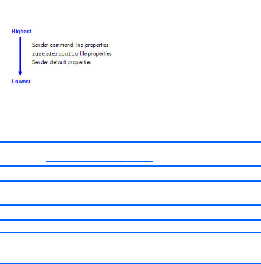
RGS Sender properties
RGS supports the following hierarchy of methods to set the Sender properties (see Figure 8-8 Sender
properties hierarchy on page 199).
Figure 8-8 Sender properties hierarchy
Properties set by methods higher on the list override properties set by methods lower on the list. For
example, a Sender command line property can override a property specified in the rgsenderconfig file.
Similarly, an rgsenderconfig file property can override a Sender default property.
The Sender, unlike the Receiver, does not support archive file properties because the Sender does not
provide a user interface that allows its properties to be modified.
Sender command line properties
See
Setting properties on the command line on page 175.
rgsenderconfig file properties
See
Setting property values in a configuration file on page 174.
Sender default properties
The Sender has a set of default properties that are built into the Sender. These are identical to the property
values in the Sender configuration file (rgsenderconfig) that is installed with the RGS Sender. However, as
noted previously, the properties in both the Receiver and Sender configuration files are initially commented
out.
Sender property groups
RGS supports the following groups of Sender properties:
●General properties group
◦Rgsender.IsRdpLogoutDetectionEnabled
◦Rgsender.IsCopyRegionEnabled
◦Rgsender.IsRegionLimitEnabled
RGS Sender properties 199
◦Rgsender.IsDisconnectOnLogoutEnabled
◦Rgsender.MaxImageUpdateRate
◦Rgsender.ImageCodec.Preferred
◦Rgsender.IsBlankScreenAndBlockInputEnabled
◦Rgsender.IsIloRemoteConsoleEnabled
◦Rgsender.IsAnonymousConnectionForceEnabled
◦Rgsender.PreferredDisplayMethods
◦Rgsender.IsCollaborationNotificationEnabled
◦Rgsender.IsReconnectOnConsoleDisconnectEnabled
●Microphone properties group
◦Rgsender.Mic.IsEnabled
●Network timeout property group
◦Rgsender.Network.Timeout.Error
◦Rgsender.Network.Timeout.Dialog
●USB access control list properties
◦Rgsender.Usb.Acl.RulesetPath
◦Rgsender.Usb.Acl.SchemaPath
◦Rgsender.Usb.Acl.RulesetErrorTimeout
●Network Interface binding properties
◦Rgsender.Network.IsListenOnAllInterfacesEnabled
◦Rgsender.Network.Interface.n.IsEnabled
◦Rgsender.Network.AllowIpAddressSubnet
◦Rgsender.Network.Port
●Clipboard property group
◦Rgsender.Clipboard.IsEnabled
Sender general properties
Rgsender.IsRdpLogoutDetectionEnabled=bool (1)
This property only applies to the Windows versions of the RGS Sender.
When a user disconnects from a RDC session, the Windows desktop on the Remote Computer is
immediately available for an RGS connection. However, if the user logs out of the RDC session, the
200 Chapter 8 RGS properties

RGS Sender will be unable to access the desktop for about 60 seconds. If this property is set to 1, the
desktop will be available to RGS almost immediately. The RGS Sender will monitor the RDC session for
a logout, and begin the process of making the desktop available as soon as the logout is detected. If
set to 0, the RGS Sender will not monitor the RDC session for a logout. The default is 1— allow quick
access to the Windows desktop after Remote Desktop logout.
Rgsender.IsCopyRegionEnabled=bool (1)
If set to 1, RGS Copy Regions are sent from the Sender to the Receiver. If set to 0, RGS Copy Regions
are turned off and will be sent to the Receiver as Image Update Regions. This is for advanced use and
should not be set. The default value is 1—send RGS Copy Regions.
Rgsender.IsRegionLimitEnabled=bool (0)
This property is used to limit the number of update rectangles in a update region. This is for advanced
use and should not be set. The default value is 0— do not limit regions.
Rgsender.IsDisconnectOnLogoutEnabled=bool (1)
If set to 1, the RGS connection will be disconnected when the user logs out. If set to 0, the RGS
connection will remain connected to the Sender when the user logs out. The default value is 1—always
disconnect when the user logs out.
Rgsender.ImageCodec.Preferred=string (NC HP2 JPEG-LS)
Available CODECs are:
●NC (HP3) The default since release 5.0
●HP2 The default prior to release 5.0
●JPEG-LS Lossless, available since 5.3.2
Introduced at RGS 5.3.2. Sets the preferred CODEC for encoding and decoding all image data sent
from the Sender to the Receiver. Both the Sender and Receiver must support the specified CODEC,
otherwise the connection will fall back to the lowest common CODEC. The system will automatically
select the best CODEC for normal use. For situations requiring a mathematically lossless CODEC, select
JPEG-LS. Note the JPEG-LS codec ignores the Rgreceiver.ImageCodec.Quality property.
Rgsender.MaxImageUpdateRate=int (30)
This property limits the number of image updates per second transmitted from the Remote Computer to
the Local Computer. The value is the maximum number of updates per second. If the image update rate
is too high, and using too much network bandwidth, the MaxImageUpdateRate can be set to limit the
number of image updates per second. The default value is 30. To specify no limit on the number of
image updates per second, set the property to 0—this is interpreted to mean that the image update rate
should not be limited.
NOTE: Beginning at RGS 5.2.5, the default value of the preceding property was changed from 0 to
30.
Rgsender.IsBlankScreenAndBlockInputEnabled=bool (1)
If set to 1, this property enables monitor blanking on certain Remote Computers when a primary user
logs in from a Local Computer. This property also enables blocking of input from a keyboard and
RGS Sender properties 201

mouse that are directly connected to the Remote Computer. If set to 0, monitor blanking is disabled. The
default value is 1— monitor blanking is enabled. For details on monitor blanking, see Remote
Computer monitor blanking operation on page 107.
Rgsender.IsIloRemoteConsoleEnabled=bool (0)
This property is supported only on Linux. If set to 0, the iLO (integrated Lights-Out) console is disabled
when an RGS connection is made. This prevents the user’s desktop session from being visible through
the iLo remote console. When set to one, the user’s desktop session will be viewable through the iLO
remote console. The default is 0—disable viewing of the user’s desktop session through iLO.
Rgsender.IsAnonymousConnectionForceEnabled=bool (0)
By default, Easy Login is only enabled on a blade workstation. To enable Easy Login functionality on a
standalone workstation, this property value can be changed from 0 to 1.
CAUTION: Enabling the above property on a standalone workstation Remote Computer may allow a
Local Computer user unauthorized access to the Remote Computer. If Easy Login is enabled via this
property, a Local Computer user can connect to the logged out or locked desktop of the Remote
Computer without providing a username or password. If a user at the Remote Computer console logs in
or unlocks the desktop, the anonymous Local Computer user will be promoted to a primary user.
This will result in the Remote Computer monitor being blanked, and the Remote Computer input
disabled. At this point, the unauthorized Local Computer user will have full control of the Remote
Computer, possibly requiring the Remote Computer user to cycle power on the computer to regain
control.
Rgsender.PreferredDisplayMethods=string(GPU ChangeList Comparitron)
Introduced at RGS 5.3.0, this property controls the order of and use of the three methods the RGS
Sender may use to process the video stream prior to sending it to the Receiver. This property should not
normally be changed from the default built into the RGS Sender. Enter the methods in priority order of
usage. If a method is not currently supported in the system, the next method in the list will be tried. The
rgdiag tool will report which methods are supported on Windows. (see Using the RGS Diagnostics Tool
on Windows on page 80)
●"GPU" uses the Graphics Processing Unit (GPU) hardware to quickly compare one full screen to a
previous full screen. A specific graphics card and driver are required. The RGS Sender will test for
the availability of the graphics card and driver. This method is supported only on Windows Vista
and later.
●"ChangeList" method uses, in Windows, the RGS mirror-driver, and on Linux, the "Remote
Graphics" X server extension to detect display changes. Microsoft Vista and later is forced to
Basic mode. Aero mode is not supported.
●"Comparitron" method uses the system's CPU to compare one full screen to a previous full screen.
This method is supported only on Windows. Animated cursors are displayed as a static cursor.
Rgsender.IsCollaborationNotificationEnabled=bool (1)
Introduced at RGS 5.2.0, this property allows the user to enable or disable display of the collaboration
notification dialog (see Collaboration notification dialog on page 116 ). If set to 1, the collaboration
notification dialog is displayed. If set to 0, the collaboration notification dialog is not displayed. The
default value is 1—display the collaboration notification dialog.
202 Chapter 8 RGS properties

CAUTION: Caution is advised in disabling the collaboration notification dialog because neither the
Remote User (if present) or the Local Users will be notified who is participating in a collaboration
session. Furthermore, if display of the collaboration notification dialog is disabled, the warning dialog
in Figure 5-7 Local Computer warning dialog if the Remote Computer is unable to blank its monitor
on page 108 (which is displayed when the Remote Computer is unable to blank its monitor) will also
be prevented from being displayed.
Rgsender.IsReconnectOnConsoleDisconnectEnabled=bool (1)
Introduced at RGS 5.3.0, this property allows the user to enable or disable session reconnection during
session logout. Supported on Windows Vista and later. The default value is 1. See Sender and
Receiver interoperability on page 15 for more details.
Microphone property group
Rgsender.Mic.IsEnabled=bool (1)
This property is new with RGS 5.1.3, and is only supported on the Windows Sender. If set to 1, remote
microphone is enabled (on/unmuted). If set to 0, remote microphone is disabled (off/muted). The
default value is 1—remote microphone is enabled (on/unmuted).
Sender network timeout properties
Rgsender.Network.Timeout.Error=int (30000)
The timeout in milliseconds used to detect and disconnect an inactive connection. The default value is
30,000 milliseconds (30 seconds). See Adjusting Network timeout settings on page 148 for more
details.
Rgsender.Network.Timeout.Dialog=int (15000)
The timeout in milliseconds used to display and wait on responses from input dialogs, such as the
authorization dialog and PAM authentication dialog. The default value is 15,000 milliseconds (15
seconds). See Adjusting Network timeout settings on page 148 for more details.
Sender USB access control list properties
The following properties provide information on the access control list (ACL) file used to control the
attachment of USB devices to a Remote Computer. See Remote USB Access Control List on page 141
for information on the ACL file.
Rgsender.Usb.Acl.RulesetPath=string (hprDefaultUsbAcl.xml)
This property specifies the name of the XML file that implements the remote USB Access Control List
(ACL).
Rgsender.Usb.Acl.SchemaPath=string (hprUsbAcl.xsd)
This property specifies the name of the schema file that accompanies the remote USB XML file.
Rgsender.Usb.Acl.RulesetErrorTimeout=int (5000)
RGS Sender properties 203

This property is used by the Sender remote USB code while monitoring the ACL file
(hprDefaultUsbAcl.xml). If this file disappears or otherwise becomes inaccessible while the Sender is
running, this property controls how long the Sender waits for the file to be restored. If the timeout
expires, all currently connected USB devices are disconnected. If the file is restored prior to expiration
of the timeout period, the USB devices remain connected. The default timeout value is 5,000
milliseconds (5 seconds).
Network Interface binding properties
The following properties permit control of which network interface the RGS Sender binds to. Use of the
network interface binding properties is described in Network Interface reconfiguration using the Sender
network interface binding properties on page 97.
Rgsender.Network.IsListenOnAllInterfacesEnabled=bool(1)
This property can be used to force the Sender to listen for RGS connections on all network interfaces.
As of RGS 5.4.0 the default value is 1— force the Sender to listen for RGS connections on all available
network interfaces.
Rgsender.Network.Interface.n.IsEnabled=int(see below for default values)
This property can be used to specify the network interface that the Sender will listen on. The “n” in the
property name specifies the index of the network interface, beginning at 0 for the first network
interface, 1 for the second network interface, and so on. If this property value is 1 (enabled), the
Sender will listen on the network interface of index “n”. If the property is 0, the Sender will not listen on
that network interface.
If Rgsender.Network.IsListenOnAllInterfacesEnabled=1, this property is ignored, and the Sender will
listen for RGS connections on all network interfaces.
If Rgsender.Network.IsListenOnAllInterfacesEnabled=0, the Sender will listen on any network interface
“n” where Rgsender.Network.Interface.n.IsEnabled=1.
The default values for this property are as follows:
●For n=0, the default is 0— The default changed from 1 to 0 beginning with RGS 5.4.0, do not
listen on this network interface (See Networking support on page 16 for details of new behavior in
RGS 5.4.0).
●For n>1, the default value is 0—do not listen on these network interfaces
Rgsender.Network.AllowIpAddressSubnet=string (all IP addresses)
This property is used to specify the range of IP addresses that the Sender will listen on for an RGS
connection request from the Receiver. A network interface must be enabled, and its IP address must be
in the range specified by this property, in order for the Sender to listen on the network interface. The
format for this property is:
xx.xx.xx.xx/yy — IP address and netmask in CIDR notation
If Rgsender.Network.IsListenOnAllInterfacesEnabled=1, this property is ignored, and the Sender will
listen for RGS connections on all network interfaces.
204 Chapter 8 RGS properties

If Rgsender.Network.IsListenOnAllInterfacesEnabled=0, the Sender will listen on any network interface
“n” where Rgsender.Network.Interface.n.IsEnabled=1, and the Receiver IP address is in the range
specified by this property.
Rgsender.Network.Port=int (42966)
This property controls the port used for communications with the RGS Sender. If this property is not
specified, the Sender will listen on port 42966, which is the default port used by the Receiver in
establishing a connection to the Sender. If this property is used to modify the Sender port number, the
user will need to specify the same port number on the Receiver to establish a connection with the
Sender, as described in Using RGS in Normal Mode on page 101.
Sender clipboard property
Rgsender.Clipboard.IsEnabled=bool (1)
If set to 1, Remote Clipboard is enabled—specifically, the copy and cut functionality in the Remote
Display Window is enabled. If set to 0, the copy and cut functionality is disabled. The default value is 1
—Remote Clipboard is enabled.
Rgsender.Clipboard.IsAlwaysAuthorized=bool (1)
If set to 1, Remote Clipboard works on a limited permissions receiver window for collaboration mode.
RGS Sender properties 205
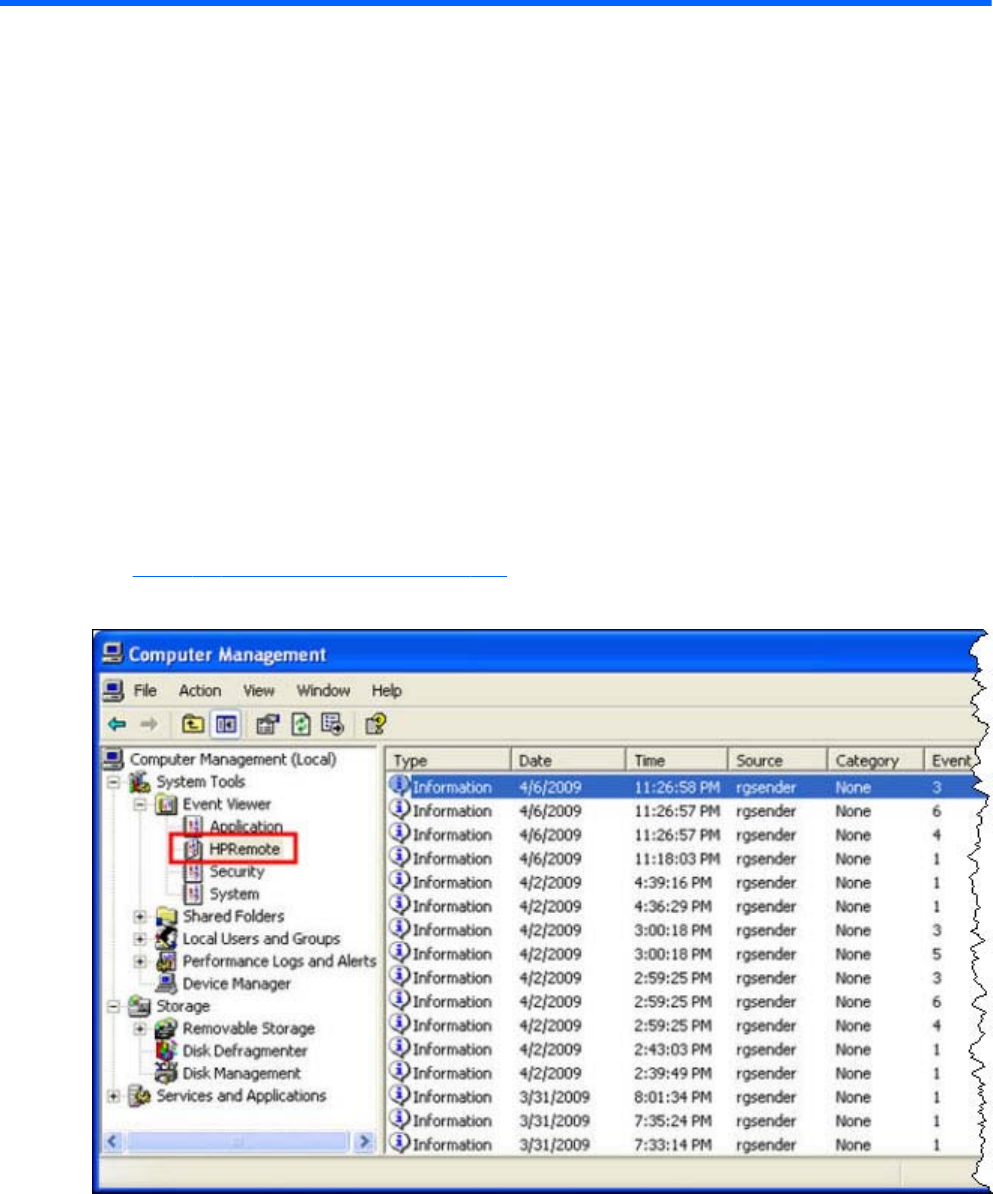
9 Sender event logging on Windows
The RGS Sender on Windows supports event logging. Event logging provides information useful for
troubleshooting connection problems, and can also be used to automatically terminate applications on
the Sender in case the connection is lost between the Sender and the Receiver. This chapter describes
the Sender event logging capabilities while the next chapter describes how to use event logging to
terminate applications on the Sender.
The HPRemote log
The Sender event log is called the HPRemote log, and can be viewed using the Windows Event Viewer
(see Figure 9-1 The HPRemote log on page 206)
Figure 9-1 The HPRemote log
To view the HPRemote log, bring up the above dialog by selecting:
Control Panel > Administrative Tools > Computer Management
206 Chapter 9 Sender event logging on Windows
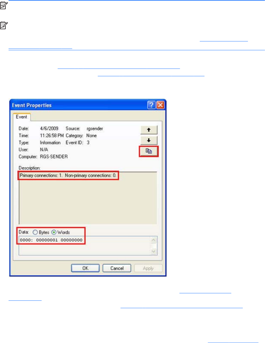
Then, in the left pane, select System Tools followed by Event Viewer—the HPRemote Event Viewer is
highlighted. The HPRemote log reflects recent RGS connection activity. The log entries are in "Last In,
First Out" (LIFO) order. By default, the most recent events are listed first.
NOTE: RGS event logging is supported only on the RGS Sender on Windows. It is not supported on
the RGS Receiver.
NOTE: The HPRemote log allows you to implement a capability called Remote Application
Termination. Remote Application Termination enables applications on the Sender (Remote) Computer to
be automatically terminated if the RGS connection to the Receiver is lost. See Remote Application
Termination on page 211 for details.
To view the properties of a particular event, double-click the event of interest—this brings up the Event
Properties window. Figure 9-2 Event Properties window on page 207 shows the Event Properties
window for the highlighted event in Figure 9-1 The HPRemote log on page 206. As you can see, the
Sender event that has been logged is the Sender connection state.
Figure 9-2 Event Properties window
The highlighted radio buttons allow viewing of the connection data (in this case, the number of primary
and non-primary connections) in byte and word formats. The Section HPRemote log format
on page 211 provides more details on the supported data formats. To copy the details of an event to
the Clipboard, click the highlighted button in Figure 9-2 Event Properties window on page 207. By
doing a paste into, for example, Notepad, you can view a text listing of the event details.
Whenever the Local Computer (Receiver) either establishes a connection to the Sender or disconnects
from the Sender, the IP address and port number of the Local Computer are logged in the HPRemote
log. At RGS 5.2.5, logging of the hostname was added to the HPRemote log. In Figure 9-3 Reporting
The HPRemote log 207
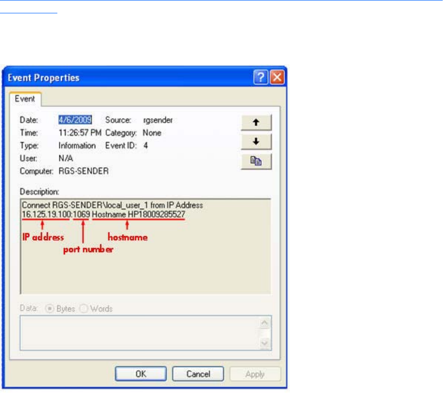
of the Local Computer IP address, port number and hostname when a connection is made to the Sender
on page 208, a connection has been established to the Sender from a Local Computer with IP address
16.125.19.100, port number 1069, and hostname HP18009285527.
Figure 9-3 Reporting of the Local Computer IP address, port number and hostname when a
connection is made to the Sender
208 Chapter 9 Sender event logging on Windows

Usages of the HPRemote log
The HPRemote log has several important usages:
●Troubleshooting—The HPRemote log can be used to aid troubleshooting of connection issues
between the RGS Sender and Receiver. If you’re unable to view the HPRemote log because of
RGS connection difficulties, Remote Desktop can be used to connect to the Remote Computer to
view the HPRemote log.
●Automatic Remote Application Termination—Network outages or loss of connectivity
between a Remote and Local Computer can leave a remote desktop session running without
supervision. To prevent applications from running unattended, a customer-designed agent can use
the HPRemote log to monitor the status of connections to determine if application termination is
required. If so, the agent would be designed to take the appropriate action to terminate the
application.
The Chapter Remote Application Termination on page 211 , describes how to create an agent
that uses the HPRemote log to automatically monitor the connection between the Remote and Local
Computers—and then take whatever action you require. Sample code is provided to facilitate
creation of the agent.
●Other automated actions—The basic principle behind using the HPRemote log to perform
automatic Remote Application Termination can be used to create an agent to automatically
monitor and process any of the events logged by the RGS Sender. The Section, HPRemote log
format on page 211 , lists the events logged by the RGS Sender, and describes their format.
Using the sample code provided, you can create an agent to automatically monitor and process
any Sender events.
Usages of the HPRemote log 209
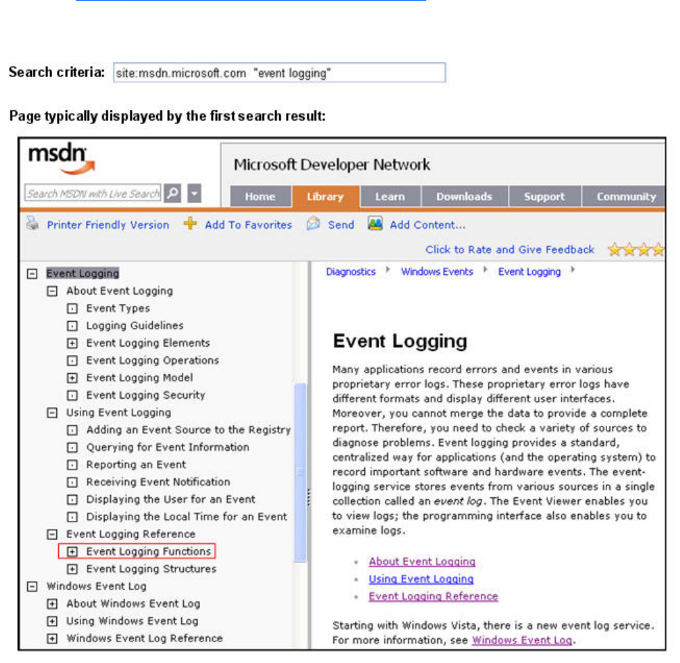
Additional information on event logging
For additional information on Windows event logging, search Microsoft Developer Network (MSDN)
as shown in Figure 9-4 MSDN event logging information on page 210. Clicking on the first search
result will typically display the page shown.
Figure 9-4 MSDN event logging information
210 Chapter 9 Sender event logging on Windows

10 Remote Application Termination
This chapter describes how to create a Windows agent on the Sender that provides Remote Application
Termination. “Remote application” refers to user applications that are running on the Remote Computer
(Sender). The sample agent described in this chapter is designed to terminate applications on the
Sender when an RGS disconnect occurs.
RGS connection and user status
As described in Establishing an RGS connection using Standard Login on page 21, an RGS connection
normally require two authentication steps:
●The first authentication step is from the RGS Receiver to the RGS Sender—this is called
authenticating the RGS connection. The dialog for this authentication step is generated and
displayed by the RGS Receiver on the Local Computer.
●The second authentication step is when logging into or unlocking the Remote Computer desktop
session—this is called logging into the Remote Computer. The login or unlock dialog is generated
by the Remote Computer, and is displayed in the Remote Display Window on the Local Computer.
A desktop session can operate independently of the RGS connection. This allows a user to disconnect
and reconnect to desktop sessions as part of a normal workflow. However, when an RGS connection is
unintentionally disconnected, the user may require remote applications to be terminated to prevent them
from operating unsupervised.
The sample agent described in this chapter monitors the number of primary users connected to the
Remote Computer. When the number of primary users drops to zero, the agent terminates all
applications on the Remote Computer. To determine the number of primary users, the agent reads and
interprets the HPRemote log.
HPRemote log format
Data in the HPRemote log consists of a Message ID followed by optional data in both character string
and binary data formats. Binary data provides direct access to data without requiring application
parsing. Character strings format the binary data into human-readable messages compatible with the
Windows Event Viewer. Table 10-1 RGS Sender events logged in the HPRemote log on page 212
shows the events logged in the HPRemote log. The Message IDs are defined in the header file
RGSenderEvents.h, and are 32-bit values. The EventID is from the Code field within the Message ID
and, for the HPRemote log, ranges from 1 to 13.
RGS connection and user status 211

Table 10-1 RGS Sender events logged in the HPRemote log
Message ID Description
RGSENDER_CONNECT_STATE
EventID: 3
The connection state consists of zero or more primary
connections and zero or more non-primary connections.
Each event entry records the current number of active
connections in each category. Events appear when the
connection status of these users changes. The first field
represents the number of primary connections. The second
field represents the number of non-primary connections. Each
state field provides a text string and binary, 32-bit unsigned
integer for application use.
Event Viewer Message:
Primary connections:%1.
Non-primary connections:%2.
Strings:
%1 = number of primary connections
%2 = number of non-primary connections
Data:
UINT32 numPrimary
UINT32 numNonprimary
Event Viewer Example:
Primary connections:1
Non-primary connections:0
RGSENDER_CONNECT
EventID: 4
NOTE: Parameter %2 is new in the RGS 5.1.5 release.
A new connection was established with an associated name.
If Easy Login is enabled, the name assignment will be
deferred until login and the associated name may be
“Anonymous”.
Event Viewer Message:
Connect %1.
Strings:
%1 = name associated with connection
%2 = IP address and port number of Local
Computer
Data:
None
Event Viewer Example:
Connect MYDOMAIN\myusername.
212 Chapter 10 Remote Application Termination

Table 10-1 RGS Sender events logged in the HPRemote log (continued)
RGSENDER_DISCONNECT
EventID 5
NOTE: Parameter %2 is new in the RGS 5.1.5 release.
A receiver has disconnected. The message will contain the
name associated with the connection. If Easy Login is enabled
and the Receiver disconnects prior to a login, the associated
name may be “Anonymous”.
Event Viewer Message:
Disconnect %1.
Strings:
%1 = name associated with connection
%2 = IP address and port number of Local
Computer
Data:
None
Event Viewer Example:
Disconnect MYDOMAIN\myusername.
RGSENDER_STARTUP
EventID: 1
Reference event registered to aid in interpretation of the event
log by Event Viewer. Signifies proper startup of the RGS
Sender service.
Event Viewer Message:
RGS Sender startup.
Strings:
None
Data:
None
RGSENDER_SHUTDOWN
EventID: 2
Reference event registered to aid in interpretation of the event
log by Event Viewer. Signifies proper shutdown of the RGS
Sender service.
Event Viewer Message:
RGS Sender shutdown.
Strings:
None
Data:
None
HPRemote log format 213

Table 10-1 RGS Sender events logged in the HPRemote log (continued)
RGSENDER_SET_PRIMARY
EventID: 6
A connection with an associated name is set as the primary
connection.
Event Viewer Message:
Set %1 as primary connection.
Strings:
%1 = name associated with connection
Data:
None
Event Viewer Example:
Set MYDOMAIN\myusername as primary
connection.
RGSENDER_SET_NONPRIMARY
EventID: 7
A connection with an associated name is assigned to a non-
primary status. This may happen as a result of a logout.
Event Viewer Message:
Set %1 as non-primary connection.
Strings:
%1 = name associated with connection
Data:
None
Event Viewer Example:
Set MYDOMAIN\myusername as non-primary
connection.
RGSENDER_ASSIGN_USER
EventID: 8
If Easy Login is enabled, the assignment of the name will be
deferred until login. When the name is assigned, this message
will be generated.
Event Viewer Message:
Assign %1 connection to %2.
Strings:
%1 = original name of connection
%2 = new name of connection
Data:
None
Event Viewer Example:
Assign Anonymous connection to MYDOMAIN
\myusername.
214 Chapter 10 Remote Application Termination

Table 10-1 RGS Sender events logged in the HPRemote log (continued)
RGSENDER_USB_CONNECT_DEVICE
EventID: 9
A new USB device was connected to the Sender via remote
USB.
Event Viewer Message:
USB Device Connect:Class=%1, Vendor ID=%2,
Product ID=%3, Manufacturer=%4, Product=%5
Strings:
%1 = USB device class
%2 = USB device vendor ID
%3 = USB device product ID
%4 = USB device manufacturer string
%5 = USB device product string
Data:
None
HPRemote log format 215

Table 10-1 RGS Sender events logged in the HPRemote log (continued)
RGSENDER_USB_DISCONNECT_DEVICE
EventID: 10
A new USB device was disconnected to the Sender via remote
USB.
Event Viewer Message:
USB Device Connect:Class=%1, Vendor ID=%2,
Product ID=%3, Manufacturer=%4, Product=%5
Strings:
%1 = USB device class
%2 = USB device vendor ID
%3 = USB device product ID
%4 = USB device manufacturer string
%5 = USB device product string
Data:
None
RGSENDER_CONNECT_USB_DENIED
EventID: 13
A USB device connection was denied by the USB access
control list.
Event Viewer Message:
USB Device Connect:Class=%1, Vendor ID=%2,
Product ID=%3,
Strings:
%1 = USB device class
%2 = USB device vendor ID
%3 = USB device product ID
Data:
None
216 Chapter 10 Remote Application Termination
Agent design issues
Designing an agent to provide Remote Application Termination requires consideration of a number of
issues in order to minimize data loss and determine when a last-resort shutdown of a disconnected
desktop session is required. Listed below are several topics to consider when designing application
control agents for your environment. The topics are not exhaustive—use them as a starting point for a
more complete design that meets your business requirements.
Desktop session logout
●Situation—In some circumstances, loss of a primary user connection should trigger a full
shutdown of all applications and force a logout of the desktop session (perhaps after a specified
time limit for reconnection has expired). This action would drop all connections to the remote
session.
●Benefit—Implementing a full desktop session shutdown/logout ensures that all connection activity
ceases immediately and ensure that applications are prevented from further unattended actions.
Shutdown of a remote session frees the workstation for connection by other users. This approach is
the most absolute and secure solution for desktop session management. Agent relies upon
Windows logout routines to terminate environment—simple in design and result.
●Issue—Forcing a desktop session shutdown/logout can result in data loss for any open
applications on the desktop session. Forcing session logouts can result in application alert prompts
requiring user interaction to save altered data. These prompts can delay or halt an interactive
logout. Session termination also destroys memory of window placement on the desktop, and
requires user intervention at restart.
Selective environment shutdown
●Situation—Partial shutdown of an environment only terminates specific applications of interest. It
does not implement a full desktop session logout. It selectively protects only the most critical
applications requiring oversight and control.
●Benefit—Preserves the active desktop session for connection at a later time. Selectively terminates
the applications of interest. Preserves data not governed by an automated shutdown policy.
Supports session recovery with an arbitrary connection time. If done in layers (giving some
applications more time to live than others), then a gradual "soft landing" shutdown can occur that
ultimately results in a full logout. Idle resources over a specific amount of time can be returned to a
remote server pool.
●Issue—Potentially more complicated to implement. Can require coordination of multiple agents to
handle layered shutdown. May still result in data loss for specific applications. May also require a
master semaphore to halt/terminate multiple agents if the user reconnects and wants to stop the
shutdown process.
Agent design issues 217
Wrapping applications of interest
●Situation—Agents can be launched that supervise only specific applications in a given
environment. Tying agents to specific applications is a selective safety net for every user.
●Benefit—Application-specific agents can be implemented as plug-ins or support utilities for a
given application. In the future, certain software providers may provide custom interfaces for safe
shutdown messages from an agent or the operating system. Custom agents can be independently
maintained and tied to specific application releases for greater support flexibility. Independent
agent design supports unit testing and decouples environmental dependencies.
●Issue—Users need specific recourse to disarm an agent if they reconnect. Applications may not
interact well with a dedicated agent (and only shutdown due to a global shutdown request).
Dedicated agents could possibly be compromised.
Administrator alerts
●Situation—Instead of shutting down an environment, an agent can be designed to alert an
administrator or operator to determine the status of the user before taking action. This watchdog
approach can further be defined to exploit redundant network connection support to a remote
system to allow user-directed shutdowns to occur.
●Benefit—System agents are not required to take destructive action—they serve only as alarms
and monitors for alternative human intervention.
●Issue—May require redundant networking channel. Requires administrator or operator
availability to support.
Anticipating user disconnects and reconnects
●Situation—Users must first be warned about the consequences of disconnection. Agents that
provide protection for a disconnected session may become a nuisance for unsuspecting users if
they fail to address protective measures in place for their safety. For example, users must know
how much time they have to reconnect before safeguards take action. If a remote agent arms itself
for application termination, users should be presented with a large, unmistakable disarming "opt-
out" panel that, upon login and discovery, they can halt any agent actions before termination.
Organizations should carefully discuss and publicize safety measures due to potential data loss.
●Issue— Users should not be able to disable or specify their own timeouts due to potential
irreversible data loss.
General agent design guidelines
In developing an agent, HP recommends following these guidelines:
●The agent should externally log its decisions and actions for postmortem analysis.
●Independent agents should provide their own opt-out, disarming dialogs with countdown feedback
before taking action.
218 Chapter 10 Remote Application Termination
●Expect the unexpected—where possible, limit your actions to those areas you are certain of the
outcomes to minimize loss of data and productivity.
●Always inspect error codes when reading event logs—the reliability of this RGS communication
method depends upon the Windows Event Log system. While we have yet to see a failure in this
path, we recommend using all information available to its fullest potential.
Agent design issues 219

Sample Agent
The sample Windows agent presented below monitors the HPRemote event log and interprets its events.
Comments are included in the agent code showing where additional code would be added to
determine if the number of primary users has dropped to zero. If so, further code can be added to
terminate applications on the Sender. A number of design issues for the Windows agent are described
in the previous section.
The sample code is a fixed-polling Windows agent that reads and interprets the HPRemote event log.
The agent uses two functions:
1. processEvent(eventServer, eventSource, dwEventNum)
◦open event log, read event dwEventNum, close event log
◦if a valid read, process recognized EventIDs, then return
2. monitorEvents(eventServer, eventSource, seconds)
◦for a finite number of seconds (or infinite if seconds <= 0) do
◦open event log, read log length, close event log
◦if log has changed, processEvent(), else sleep for X ms.
To properly use the function monitorEvents(...), the following strings must be defined in the
function call:
●LPCTSTR eventServer: if string is defined as "\\\\yourservername", then the log is stored on
a remote server - if the string is empty (NULL), then the log is stored locally (note that four
backlashes compiles to two in a string constant).
●LPCTSTR eventSource: the name of the target event generator, e.g., rgreceiver
The sample agent uses Microsoft event logging functions such as OpenEventLog, ReadEventLog,
and CloseEventLog. For information on these functions, refer to the Event Logging Functions link
highlighted in the figure used in Additional information on event logging on page 210 .
The sample agent is listed below. Where noted, user-specific code should be added. The agent header
file, RGSenderEvents.h, is installed with the RGS Sender and is located at:
C:\Program Files\Hewlett-Packard\Remote Graphics Sender\include
\RGSenderEvents.h
#include <windows.h>
#include <stdio.h>
#include "RGSenderEvents.h"
#define BUFFER_SIZE 1024 // safe EVENTLOGRECORD size for now
220 Chapter 10 Remote Application Termination
#define EVENT_SERVER NULL // remote server = "\\\\nodename"; local = NULL
#define EVENT_SRC "rgsender" // specifies specific event name source
in // HPRemote
BOOL processEvent(LPCTSTR eventServer, LPCTSTR eventSource, DWORD
dwEventNum)
{
HANDLE h;
EVENTLOGRECORD *pevlr;
BYTE bBuffer[BUFFER_SIZE];
DWORD dwRead, dwNeeded;
BOOL result;
// Open, read, close event log ===========================================
if ((h = OpenEventLog(eventServer, eventSource)) == NULL)
{
... report error status ...
return true;
}
// Set the pointer to our buffer. Strings and data will get appended to
the EVENTLOGRECORD structure.
pevlr = (EVENTLOGRECORD *) &bBuffer
// Read the event specified by dwEventNum
result = ReadEventLog(h, // event log handle
EVENTLOG_SEEK_READ | // start at specific event
EVENTLOG_FORWARDS_READ, // advance forward
dwEventNum, // record to read
pevlr, // pointer to buffer
BUFFER_SIZE, // size of buffer
&dwRead, // number of bytes read
&dwNeeded); // bytes in next record
if (CloseEventLog(h) == false)
Sample Agent 221
{
... report error status ...
return true;
}
// Process event (example: print out event) ==============================
if (result)
{
// We only know how to process specific events
if (pevlr->EventID == RGSENDER_CONNECT_STATE)
{
// Retrieve the two UINT32 fields of this message
// representing primary and non-primary connections.
unsigned int *pData = (unsigned int *)
((LPBYTE) pevlr + pevlr->DataOffset);
// Examine state of primary connections here for other
// agent response if number drops to zero...
... example only prints out retrieved record to console ...
printf ("Event: %u Primary: %u Secondary: %u\n",
dwEventNum, pData[0], pData[1]);
}
... Process other events here if desired ...
}
else
{
... report unrecognized event here ...
return true;
}
return false;
}
void monitorEvents(LPCTSTR eventServer, LPCTSTR eventSource, int seconds)
222 Chapter 10 Remote Application Termination
{
DWORD dwCurrentIndex = 0;
DWORD dwCurrentStart;
DWORD dwCurrentCount;
DWORD dwNewIndex;
int waitedFor;
// This function will monitor the log for the specified number of
// seconds. If seconds is less than zero, we will wait forever.
for (waitedFor = 0; seconds < 0 || waitedFor < seconds; )
{
HANDLE h;
// Open, read status of log, close event log =========================
if ((h = OpenEventLog(eventServer, eventSource)) == NULL)
{
... report error status here ...
return;
}
// If an event is added, either the start or count will change.
// Get the start and count. Microsoft does not specify what
// reasons these functions could fail, so we cannot ensure
// success. Check the return value.
if (GetOldestEventLogRecord(h, &dwCurrentStart) == false ||
GetNumberOfEventLogRecords(h, &dwCurrentCount) == false)
{
CloseEventLog(h);
... report error - unable to obtain event logs ...
return;
}
if (CloseEventLog(h) == false)
{
Sample Agent 223
... report error status here ...
return;
}
// Determine state of log change =====================================
// Compute the index of the last event. If the count is zero, then
// there are no events and the index is 0.
if (dwCurrentCount == 0)
{
dwNewIndex = 0;
}
else
{
dwNewIndex = dwCurrentStart + dwCurrentCount - 1;
}
// If the new index is different than the current, update the current
// and process the current event. Otherwise, we sleep for a while.
if (dwNewIndex != dwCurrentIndex)
{
// We have at least one new event. Print out the last event.
dwCurrentIndex = dwNewIndex;
if (dwNewIndex)
{
if (processEvent(eventServer, eventSource, dwCurrentIndex))
{
... event processing error here ...
return;
}
}
}
else
224 Chapter 10 Remote Application Termination

{
// No new events. Sleep for 1 second.
Sleep(1000);
waitedFor += 1;
}
}
return;
}
main( ... )
{
... setup and initialize agent ...
monitorEvents(EVENT_SERVER, EVENT_SRC, seconds);
... cleanup agent here or send alerts ...
... may wish to return status from monitorEvents ...
}
Additional features for Windows systems
The following optional procedures for the RGS Sender service can improve the reliability of your remote
agent solution.
RGS Sender Service Recovery Settings
This section discusses restart options for the RGS Sender and possible interactions of the agent with the
Sender.
●By default, most Windows services are installed without any automatic restart/recovery settings.
This means that, when a service terminates, Windows will, by default, not restart the service unless
explicitly set. When RGS Sender software is first installed, it is installed with the Windows default
(do not restart).
●Restarting the RGS Sender service can support RGS reconnection with a RGS Receiver client
(unless a system error prevents the RGS service from restarting).
●In designing the agent, you should consider whether or not to check for the existence of a running
RGS Sender service as an indication of a sufficient primary user connection. If service restarts are
programmed for your environment, this test may be unnecessary.
Additional features for Windows systems 225
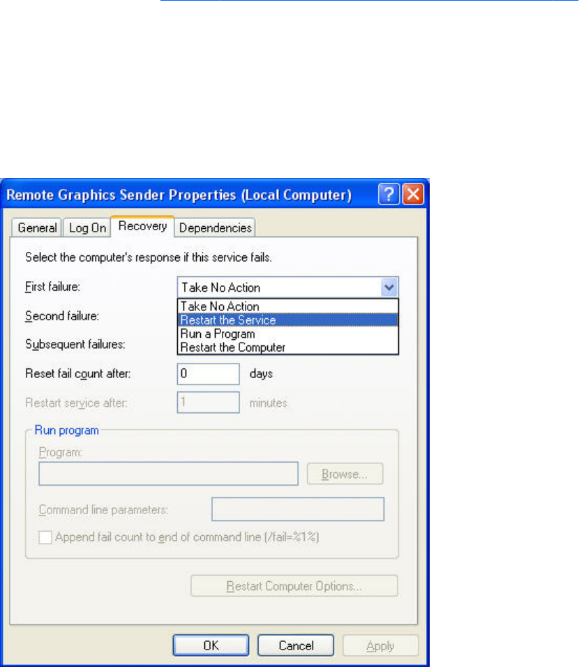
●To set the RGS Sender service for automatic restart, you must adjust its Recovery Property
through the Administrative Tools and Services control panel options.
●Actions to take for the first failure, second failure, and subsequent failures are available in the
properties menu (see Figure 10-1 Remote Computer Sender recovery options on page 226). The
Recovery options include:
◦Take No Action
◦Restart the Service
◦Run a Program
◦Restart the Computer
Figure 10-1 Remote Computer Sender recovery options
Microsoft Remote Desktop Recovery
If the RGS Sender becomes unavailable and the Receiver can no longer connect to the Sender, a
Windows system with Remote Desktop services enabled can access the Remote Computer to diagnose
the issue.
226 Chapter 10 Remote Application Termination

11 Optimizing RGS performance
This chapter provides suggestions on optimizing RGS performance, including optimizing the Remote
Computer display settings and the network configuration.
Performance tuning for all platforms
The following suggestions apply to all platforms:
●Set the network to full-duplex mode—To obtain the best performance, the network between the
RGS Sender and RGS Receiver should operate in full-duplex mode.
●Disable transition effects—Do not use color or animated cursors on the Remote Computer.
Although RGS displays color and animated cursors very well, this typically requires more network
bandwidth and CPU resources.
●Set the Remote Computer desktop background to a solid color to minimize the amount of image
data that needs to be sent. On Windows, perform the following:
◦Select the Control Panel
◦Bring up the Display Properties window
◦Select the Desktop tab, and set the background to None. Alternatively, select the Themes
tab, and select Windows Classic in the Theme box.
●Set the Sender and Receiver to 32 bits per pixel—On Windows, perform the following:
◦Select the Control Panel
◦Bring up the Display Properties window
◦Select the Settings tab, and set the Color Quality to Highest (32-bit)
●Lower the Sender display resolution—RGS is an image-based remote visualization technology.
Therefore, lowering the display resolution can significantly improve performance.
Performance tuning for all platforms 227

Performance tuning for Windows
This section provides performance tuning tips for RGS on Windows.
1. Lock desktop icons on the Remote Computer by performing the following steps:
●Select the Control Panel
●Bring up the Display Properties window
●Select the Desktop tab and select Customize Desktop.
●On the Web tab, check Lock desktop items.
2. Sender process priority—Occasionally, an activity such as rotating a model in a 3D design
program may appear slow and erratic, and image update may appear inconsistent. If the Sender
is running on Windows, OS scheduling may be an issue. This can often be resolved by increasing
the process priority of the Sender. See the Setting the Windows Sender process priority
on page 64 for further details.
3. Java Applications—Some versions of the Java Runtime Environment use DirectX. To see screen
updates on Windows XP Professional with these versions of Java, Automatic 3D Updates must be
enabled (see Using the rgadmin tool on page 81). Rendering through DirectX will often cause the
entire DirectX window to be registered as a screen modification. This can result in higher
bandwidth and slightly higher CPU utilization by the Remote Graphics Sender. In some cases,
performance may be improved by using GDI rather than DirectX with Java.
●To use GDI with Java, the "-Dsun.java2d.noddraw=true" option needs to be supplied to the
java or javaw executable. For example:
java -Dsun.java2d.noddraw=true SomeApp
●This can be done by passing this option on the command line or adding this option to the
_JAVA_OPTIONS environment variable. For example:
set _JAVA_OPTIONS=-Dsun.java2d.noddraw=true
java SomeApp
Troubleshooting graphics performance
Graphics adapter frame buffer read performance
The dominant factor impacting performance on the Sender is the frame buffer read performance of the
graphics adapter. Frame buffer read performance of at least ten frames per second is recommended for
optimum RGS performance.
RGS uses the Remote Computer graphics adapter to accelerate rendering of the image. After the image
on the Remote Computer is modified, the RGS Sender reads the rendered image from the frame buffer,
compresses it, and transmits it to the Receiver.
228 Chapter 11 Optimizing RGS performance

On Windows, use BltTest to test the frame buffer read performance of the Remote Computer. This tool is
available at: http://www.stereopsis.com/blttest/
Configuring your network for optimal performance
RGS depends on low network latency and reasonably high network bandwidth. There are several
methods to test and measure the network bandwidth, latency, and the number of hops between Sender
and Receiver computers:
●Use the ping command to measure network latency. From a command prompt on Windows or a
terminal window on Linux, execute ping hostname. This will report the network latency. Be sure the
ping protocol (ICMP) is not blocked by a firewall. Windows may be set up with IPSec filters—be
sure there is no IPSec filter policy disabling ICMP traffic.
●Use Traceroute (Linux) or tracert (Windows) to measure the network latency between two
computers. Traceroute will report the number of hops it takes to reach a computer in addition to
the network latency.
●Use ttcp to measure the network bandwidth. ttcp is available at:
http://www.pcausa.com/Utilities/pcattcp.htm
Once you’ve characterized your network performance, you can decide if improvement is required.
Several possible steps are described below.
The computer network interface will auto-negotiate the network speed with the network switches on the
local network. The negotiated speed can vary from 10 Mb/sec half duplex to 10 Gb/sec full duplex.
Most modern network interfaces and switches will negotiate the highest possible speed available.
However, unless the network has been carefully designed for maximum throughput, the network
interfaces and switches may auto-negotiate to a sub-optimal speed.
If the network interface and switches are configured to auto-negotiate properly, you can leave the
settings to auto-negotiate. If you want to force the network to operate at a particular speed, the settings
in the network interface and switches can be hardcoded. You must be careful with these settings,
however. If the network interface and switch settings don’t complement each other, the network will
have poor performance.
●Configuring the network interface on Windows—You can change the link speed and
duplex mode on Windows by opening the Device Manager. Click Control Panel > System >
Hardware Tab > Device Manager. Once the Device Manager is open, click the + next to
Network adapters. Then, right-click the network adapter that you want to change, and select
Properties. Click the Advanced tab. Each network adapter has its own properties/settings that
can be changed. The property that affects the link speed and duplex is usually named "Link Speed
& Duplex". Click that property. If you want auto-negotiation, select the Auto Detect entry in the
Value box. If you want to hard-code the speed and duplex, always choose the fastest link your
network can support, and always choose full duplex.
●Configuring the Network Interface on Linux—On Linux systems, the ethtool tool can be
used to configure networking. Perform the following steps to obtain and set the network
characteristics on Linux. To obtain the LAN characteristics for interface 0, as root, type:
$ /usr/local/sbin/ethtool eth0
Configuring your network for optimal performance 229
To set the LAN characteristics for a 100 Mb/sec connection running full-duplex mode, as root,
type:
$ /usr/local/sbin/ethtool -s eth0 speed 100 duplex full autoneg off
If you are not satisfied with your network performance, look at the log files on your network switch (if
the Local Computer is connected to one). A significant number of errors on the switch port may indicate
that the computer or network is not configured correctly. Work with your IT organization to optimize
your computer and network configuration.
230 Chapter 11 Optimizing RGS performance

12 Troubleshooting RGS
This chapter provides suggestions on troubleshooting potential issues with RGS. Refer also to RGS error
messages on page 232 which lists the RGS error messages and their potential causes.
Potential RGS issues and troubleshooting
suggestions
Table 12-1 Potential RGS issues and troubleshooting suggestions on page 231 lists several potential
RGS issues, and provides a number of troubleshooting suggestions.
Table 12-1 Potential RGS issues and troubleshooting suggestions
Issue Suggestion
Cannot connect to the RGS Sender Verify that the pre-connection checklist is satisfied as
described in Pre-connection checklist on page 91.
A connection is established but it appears to time out. See the section Adjusting Network timeout settings
on page 148.
Graphics performance appears slow See Optimizing RGS performance on page 227.
Remote audio doesn’t work ●If using a Linux Receiver, verify that audio has been
installed correctly as described in Linux Receiver Audio
requirements on page 85.
●See the troubleshooting suggestions in Potential audio
issues on page 135.
Remote USB doesn’t work ●Verify that USB has been correctly configured during
Receiver installation on Windows as described in
Installing the Receiver on Windows on page 53.
●See the troubleshooting suggestions in Troubleshooting
remote USB on page 145
I want to restore the Receiver properties to factory defaults. Uninstall and reinstall the RGS Receiver.
Java applications not working as expected Use GDI with Java by disabling the use of DirectDraw. See
Performance tuning for Windows on page 228 for details.
Potential RGS issues and troubleshooting suggestions 231

13 RGS error messages
This chapter lists the error messages reported by the RGS Receiver, and describes potential reasons for
the error messages.
Receiver error messages
Error Description
Connection lost! The RGS Sender has closed the connection. Possible reasons
include:
●The Sender may have explicitly disconnected your
connection. For example a user may have selected
disconnect all connections from the Sender icon or
Sender GUI or the user may have logged off.
●Another user has connected to the Sender using the same
username and password.
●If you connected to a desktop that was not logged in and
another user logged in your connection will be
disconnected.
●If you were connected to a logged in desktop and the
logged in user disconnects your connection will be
disconnected too.
●The network may have been disconnected, closed, or
temporarily disrupted.
●The Sender service/daemon may have been stopped, re-
started, or killed.
●The Sender system may have been stopped/shutdown,
or re-started.
●If connecting to a Linux computer, the X Server may have
been stopped or re-started.
●The Sender or X Server may have experienced a failure.
Unable to connect to Sender! If this error is reported, see Pre-connection checklist
on page 91 for a list of possible causes.
232 Chapter 13 RGS error messages

Authentication failed! The RGS Sender has refused to allow a connection. Possible
reasons include the following:
●The authentication credentials that you entered, such as
domain name, user name and password, are not valid or
recognized by the Sender system.
●The Sender's authentication is not configured
appropriately. Please consult the User's manual and
README.txt for the latest directions and issues with
respect to configuring authentication.
Directory not found or not accessible! The directory file is not available. Possible reasons include:
●The directory file name or location has been mistyped.
●The file has been moved or is no longer available.
●The network is down or experiencing a disruption.
●The user does not have read permission on the file.
User not found in directory! The username of the current user of the HP Remote Graphics
Software Receiver is not found in the directory file. Possible
reasons include:
●The username entered in the directory file does not
exactly match the real username.
●The domainName entered in the directory file is
incorrect. See Directory file format on page 170 for
information about choosing the correct domainName.
●The username of the current user is not entered in the
directory. If the directory file is on a shared drive with
restrictive permissions, consult an IT specialist to add the
proper entry.
Authorization failed! The connection was authenticated, but another user is already
logged into the desktop of the Sender system. When a
connection is attempted to another user's desktop, a dialog is
displayed on the Sender desktop asking the logged in user to
allow the connection. A user is not allowed to connect to
another user's desktop unless they are explicitly allowed/
authorized. Either the connection was not granted access, or
the dialog timed-out and the connection was implicitly denied.
Error: No license found for the Sender you are trying to
connect to!
A license was not found for the RGS Sender.
Error: License Expired for the Sender you are trying to connect
to!
The license has expired for the RGS Sender.
Error: License Invalid for the Sender you are trying to connect
to!
The license is invalid for the RGS Sender.
Setup Mode hotkey sequence too short. The key sequence specified by the user is too short.
Setup Mode hotkey sequence too long. The key sequence specified by the user is too long.
Setup Mode hotkey sequence may only consist of Ctrl, Alt,
Shift and Space.
The key sequence specified by the user contains invalid keys.
Receiver error messages 233

A space may only be entered after Ctrl, Alt or Shift is pressed. The Setup Mode hotkey sequence cannot start with a space.
Setup Mode hotkey sequence is invalid. The sequence has
been reset to the default.
The Setup Mode hotkey sequence specified using a property
either on the command-line or in the property configuration
file is invalid, and has been reset to the default.
Setup Mode hotkey sequence is invalid. The sequence has
been disabled.
The Setup Mode hotkey sequence specified using a property
either on the command-line or in the property configuration
file is invalid, and the property Rgreceiver.Hotkeys.IsMutable
is disabled. Therefore, hotkeys have been disabled.
Connection denied! The iLO remote console is enabled. The iLO remote console is enabled on the HP Blade
Workstation. The Blade must be configured in User Mode
before connections are allowed.
Unable to connect to Sender: The Receiver was unable to
resolve the specified hostname or IP Address. Verify that you
entered the value correctly.
This is usually indicative of a DNS error.
Unable to connect to Sender: The Receiver resolved the
specified hostname or IP address, but cannot connect to the
Sender. Verify that the system is accessible on your network
and that the Remote Graphics Sender service has been started
and is listening on a pubic IP address and is not blocked by a
firewall.
The Receiver was able to look up and resolve the specified
hostname or IP address. However, the Receiver was unable to
establish a connection to the Sender. There are several
possibilities such as the Sender is not installed, the Sender is
not running, the Sender is listening on the wrong network
interface, or a firewall is blocking the Sender.
234 Chapter 13 RGS error messages

A Linux remote audio device support
As shown in Figure 2-24 RGS audio subsystem on Linux on page 41, an audio device is required to be
installed in Linux-based Remote Computers in order for application-generated audio to be sent to the
Local Computer. Furthermore, the audio device installed in the Remote Computer must have the ability
to record from a control that is the mix of all audio signals. On a Windows computer, by way of
comparison, this control is often called “Stereo Mix”. Linux, however, does not follow a standard
naming convention for this control—hence, the need to evaluate individual audio devices to determine
their suitability for use on Linux.
RGS will attempt to capture application generated audio from the Sender and playback the result on
the Receiver. Not all audio device drivers provide the capability to capture application generated
audio.
The following list of audio devices are known to work on Redhat EL4 and Redhat EL5:
●SoundBlaster Audigy 4—SB0660
●SoundBlaster Audigy 4—SB0610
●SoundBlaster Audigy 2ZS—SB0350
●SoundBlaster—SB0160
●SoundBlaster Live!—CT4780
●SoundBlaster Live!—CT4760
HP Personal Workstations have a high definition audio device on the motherboard. This device is
known to use a driver on Redhat EL4 and Redhat EL5 that does not allow RGS to capture application
generated audio.
The Linux virtual audio driver can be used on systems without audio hardware. In some cases, it may
be desirable to disable the physical audio device and install the virtual audio driver. See Linux Sender
Audio on page 88 for information on how to install the virtual audio driver.
IMPORTANT: The Linux virtual audio driver is the “only” supported audio device for RHEL V6.
Hardware audio devices are not supported.
NOTE: The Linux virtual audio driver is not supported in a virtual machine. Timing information from
the kernel in a virtual machine may not be precise enough to ensure consistent audio quality.
235

Index
A
Advanced capabilities 118
Authenticator properties 176
Auto Launch 123
Auto Launch session properties
196
C
Collaborating 114
D
Directory Mode 26
E
Easy Login 111
G
Game Mode 124
General options 119
H
Hotkeys 156
I
Image quality 29
Installing RGS 52
Interactive Experience controls
120
Introduction to HP Remote Graphics
Software 1
K
keyboard locales 49
L
Linux remote audio device
support 235
Logging 167
login methods 110
M
Many-to-one connection 18
Microphone property group 203
monitor blanking operation 107
monitor blanking overview 28
Multi-monitor configurations 26
N
Network Interface binding
properties 204
Network timeout settings 148
Normal Mode 26
O
One-to-many connection 19
One-to-one connection 17
operating systems 10
Optimizing RGS performance
227
P
Per-receiver properties 177
Per-session properties 180
power saving states 48
Pre-connection checklist 91
R
Receiver audio properties 190
Receiver browser properties 189
Receiver Control Panel 103
Receiver Experience properties
189
Receiver general properties 182
Receiver hotkey properties 192
Receiver image codec properties
195
Receiver logging properties 194
Receiver microphone property
190
Receiver network properties 191
Receiver properties 176
Receiver property groups 177
Receiver Remote Clipboard
properties 193
Receiver USB properties 191
Remote Application Termination
211
Remote audio 38
Remote audio operation 124
Remote Display Window Toolbar
106
Remote USB operation 136
RGS error messages 232
RGS overview 9
RGS properties 174
S
Sender clipboard property 205
Sender event logging on
Windows 206
Sender general properties 200
Sender network timeout
properties 203
Sender properties 199
Sender property groups 199
Sender USB access control list
properties 203
Setup Mode 104
Single Sign-on 112
Standard login 111
Statistics 169
Supported computers 10
T
Troubleshooting RGS 231
U
Using Directory Mode 170
236 Index
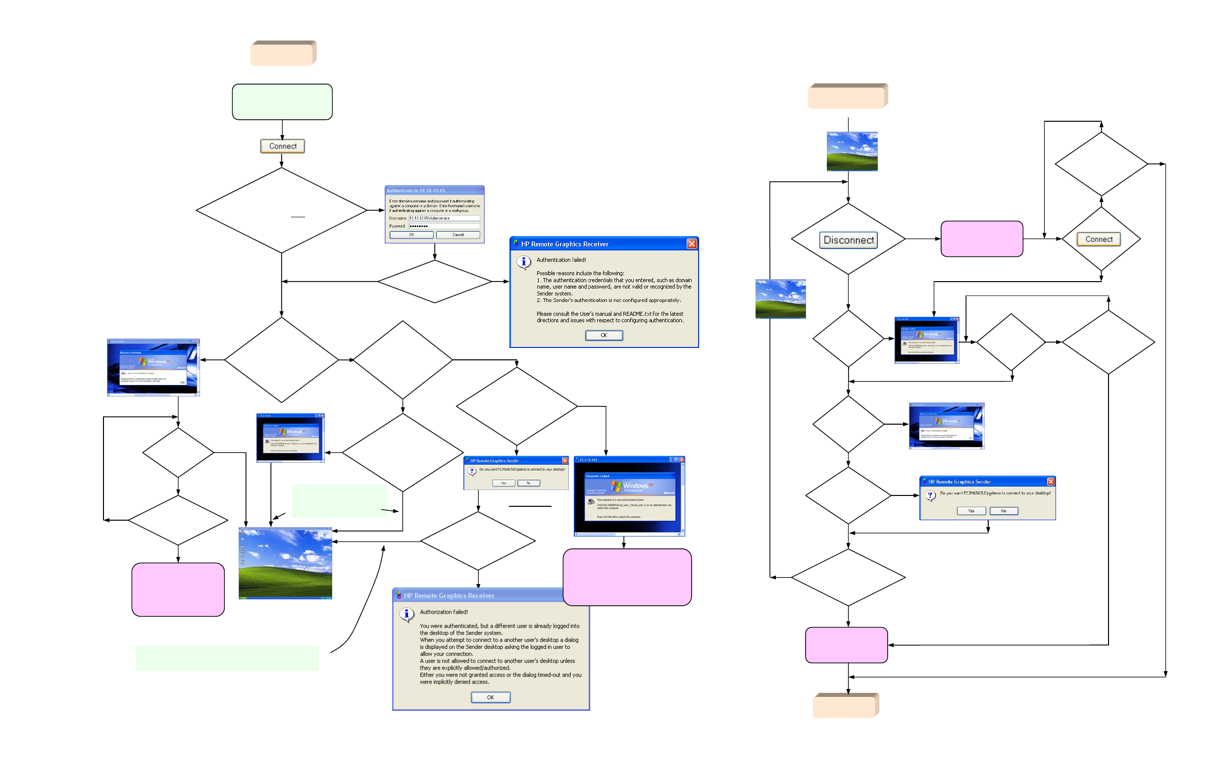
is
another
user already
logged into the
Remote Computer
(the primary
user)
?
N
has
local user
logged in
?
N
Y
N
Y
Y
has
another user
logged in
?
N
Y
do the
credentials of
local user match
the credentials of
the primary
user?
RGS authentication dialog
Attempt to connect to
Remote Computer
Y
Windows-to-Windows
connection AND local user
credentials match any credentials
on Remote Computer
?
Y
N
silent
authentication authentication
succeeded
?
N
Y
Remote Display
Window is terminated
when another user
logs in, local user
will need to reconnect
If another user attempts to connect
to the Remote Computer with the
same credentials as the local user,
the local user Remote Display Window
below will terminate.
RGS connection
established
Y
Login dialog
in Remote
Display
Window
N
Remote Display Window
is terminated when
primary user unlocks
desktop or re-connects, local
user will need to reconnect
Remote
Display
Window
This dialog is displayed
for the primary user
Remote
Display
Window
N
Is
desktop
locked or is primary
user disconnected
(but still logged
in)
?
Y
local user can unlock
local user
is now the
primary user N
In both cases, the local user
becomes the new primary
user and the prior primary
user is disconnected.
This is the collaboration path – multiple local users can
connect to the primary user’s desktop, subject to
authorization by the primary user.
Is
desktop
locked or is primary
user disconnected
(but still logged
in)
?
N
primary user
press
?
Remote Display
Window terminated
did someone
else log in with
my credentials
?
N
N
Y
Remote Display
Window terminated
Y
log out
?
Y
lock screen
?
Y
N
N
Now a local user with an
authenticated connection
did
someone else
log in with my
credentials
?
N
Y
press
?
Y
N
did I
unlock screen
?
N
Y
Remote
Display
Window
is
another
user attempting
to connect
?
Y
N
Remote
Display
Window
did
someone else
log in with my
credentials
?
N
Y
local user
now
a local
user
local user
attempt to log in
using Standard Login
“authenticating the connection”
Local user Standard Login process and primary user flowchart
Respond
to dialog
does
primary user authorize
connection
?
Standard Login Process
