HP Vectra Vl400, Technical Reference Manual Product Description Lpv06498
Vectra VL400 to the manual 11839c1e-189f-401f-81a1-ca41a36d0bba
User Manual: HP hp vectra vl400, technical reference manual - product description
Open the PDF directly: View PDF ![]() .
.
Page Count: 64

Technical Reference Manual
Product Description - Vectra VL400
This technical reference and BIOS document for Vectra VL400 PCs contains
summary information only. More detailed information on system hardware is
available in the Technical Reference Manual - Vectra Technology.
HP Vectra VL400 PCs

2

3
About this Document
This technical reference and BIOS document for Vectra VL400 PCs contains
summary information only. More detailed information on system hardware is
available in the Technical Reference Manual - Vectra Technology.
VL400 Documentation
The following documentation is available for the HP Vectra VL400.
Quick User’s Guide
This paper manual came with your PC but is also available at
www.hp.com/go/vectrasupport.
Information CD-ROM
This CD-ROM contains extensive information about your PC. It can be
ordered from www.hp.com/go/vectrasupport.
If you do not want to order this CD-ROM, you can also download individual
documents and information modules from
www.hp.com/go/vectrasupport.
The CD-ROM contains the following information modules:
• Setting up your PC
•UsingyourPC
• Installing components and accessories in your PC
• Solving problems (troubleshooting)
• Warranty information.
The CD-ROM also contains the following documents:
•ProductDatasheet
• Corporate Evaluator’s Guide
• Corporate Deployment Guide
• Technical Reference Manual (in 3 parts, the manual you are reading)
• Service Handbook chapters
• e-DiagToolsUser’sGuide.

4
VL400 Bibliography
❒HP Vectra VL400 user, troubleshooting and upgrading manuals at:
www.hp.com/go/vectrasupport
❒Technical Reference Manual -Vectra Technology
www.hp.com/go/vectrasupport
❒HP Vectra PC Service Handbook Chapter at:
www.hp.com/go/vectrasupport.
Data sheets can be obtained at:
❒Pentium Processors
www.intel.com/design/pentiumIII/datashts
❒HP Product Data Sheet
www.hp.com/desktops

Contents
English 5
1SystemOverview
PackageFeatures........................................... 8
RearConnectors.............................................. 8
Desktop .................................................... 9
Minitower.................................................. 10
SmallFormFactor........................................... 12
Specifications............................................. 14
PhysicalCharacteristics....................................... 14
EnvironmentalSpecifications.................................. 15
2 System Features
VL400SystemBoardLayout................................. 18
SystemBoard............................................... 18
ArchitecturalView......................................... 20
MainMemory............................................. 21
Processors ............................................... 21
MassStorageDevices...................................... 22
HardDiskDrives ............................................ 22
FloppyDiskDrives........................................... 22
CD-ROMandDVDDrives ..................................... 22
DVDRegionCodes...........................................25
IntegratedGraphicsController.............................. 26
SupportedResolutions........................................26
Connectors................................................. 27
MatroxMillenniumG450AGP4XorPCIGraphicsCard......... 28
KeyFeatures ............................................... 28
Maximum Supported Refresh Rates . . . . . . . . . .................... 29
Audio.................................................... 30
Network ................................................. 31
AccessoryBoards ......................................... 33
3 Serviceability
VL400Desktop............................................ 36

6English
VL400Minitower.......................................... 37
VL400SmallFormFactor.................................. 38
4BIOSOverview
BIOSSummary........................................... 40
UsingtheHPSetupProgram.................................. 40
HelpInformation............................................40
MainMenu.................................................41
AdvancedMenu.............................................41
Security ...................................................42
BootMenu .................................................43
PowerMenu................................................43
PowerSavingandErgonometry............................. 44
SoftPowerDown............................................ 44
SafeOff ................................................... 44
PowerManagement.......................................... 44
OperatingSystemPowerManagement...........................44
APMPowerManagementModes ...............................44
ACPI Power Management Modes
(Windows2000andWindows98SEonly)........................45
BIOSAddresses .......................................... 46
SystemMemoryMap......................................... 46
HPI/OPortMap(I/OAddressesUsedbytheSystem).............. 46
DMAChannelControllers.....................................48
InterruptControllers.........................................49
PCIInterruptRequestLines...................................49
Order in Which the POST Tests are Performed . ............... 50
HPe-DiagToolsPrebootDiagnostic(BeepCodes)............. 57
5 Drivers and Software
Drivers.................................................. 60
Software ................................................ 60
BIOSUpdates............................................ 61

1
System Overview
This chapter introduces the internal and external features, and lists the
specifications of the HP Vectra VL400 PC models.
8
1SystemOverview
Package Features
Package Features
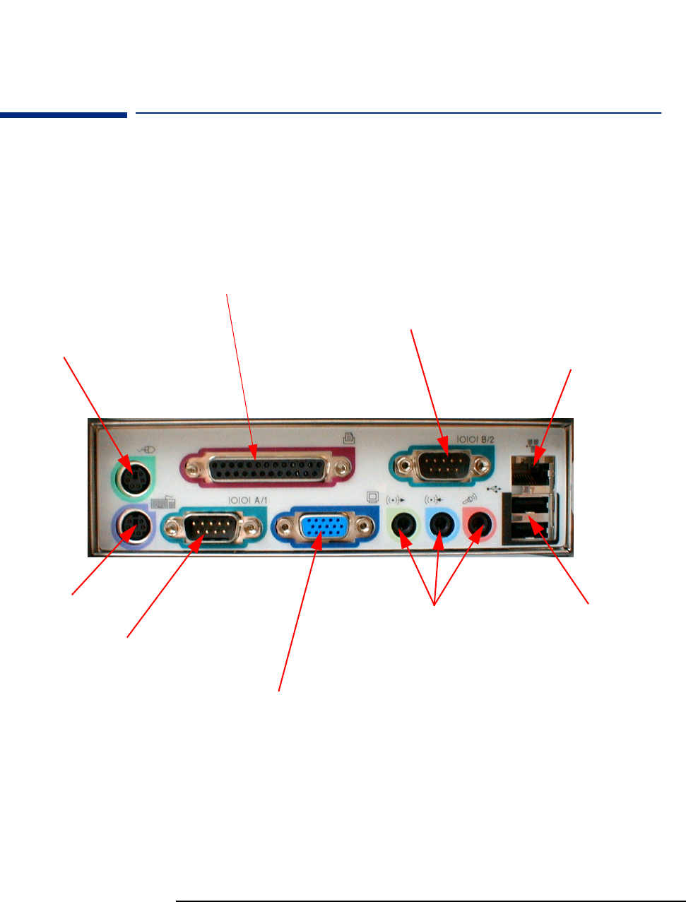
Rear Connectors
25-pin Parallel Connector
Standard Monitor Connector
This connector is disabled if the PC has an AGP graphics
card. In this case, use the graphics card’s connector.
Serial
Connector
Keyboard
Mouse
Serial
Connector
Network (LAN)
connector
2USB
Connectors
Multimedia
Connectors
9
1 System Overview
Package Features
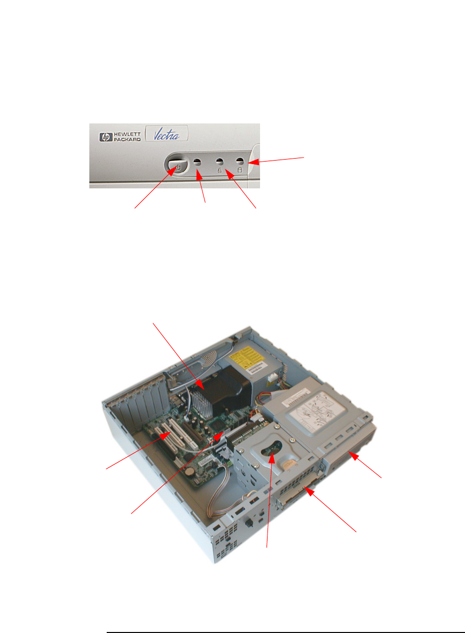
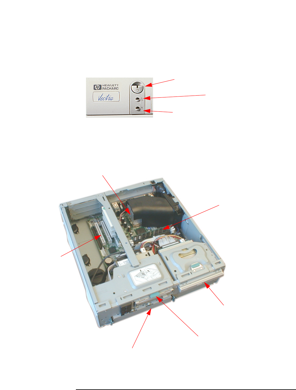
Desktop
Front panel
On/Off power
button
Power on status
light (green) Keyboard lock
status light (amber)
Disk activity light
(yellow)
Inside the Desktop
Main Memory
CD-ROM, CD-RW
drive, or DVD drive
Hard disk drive
Accessory board slots
Floppy disk drive
Processor
10
1SystemOverview
Package Features
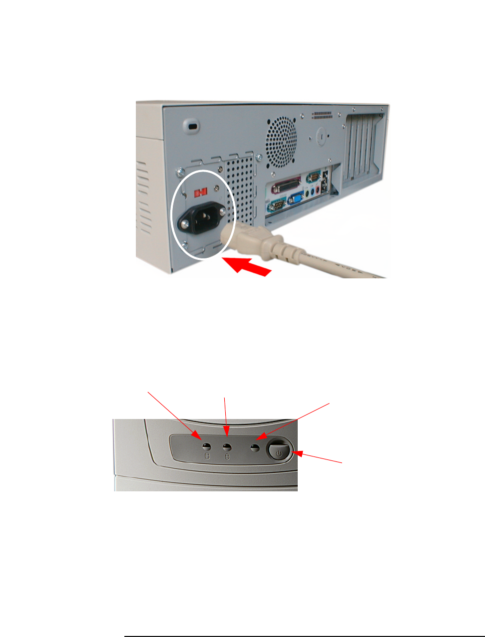
Minitower
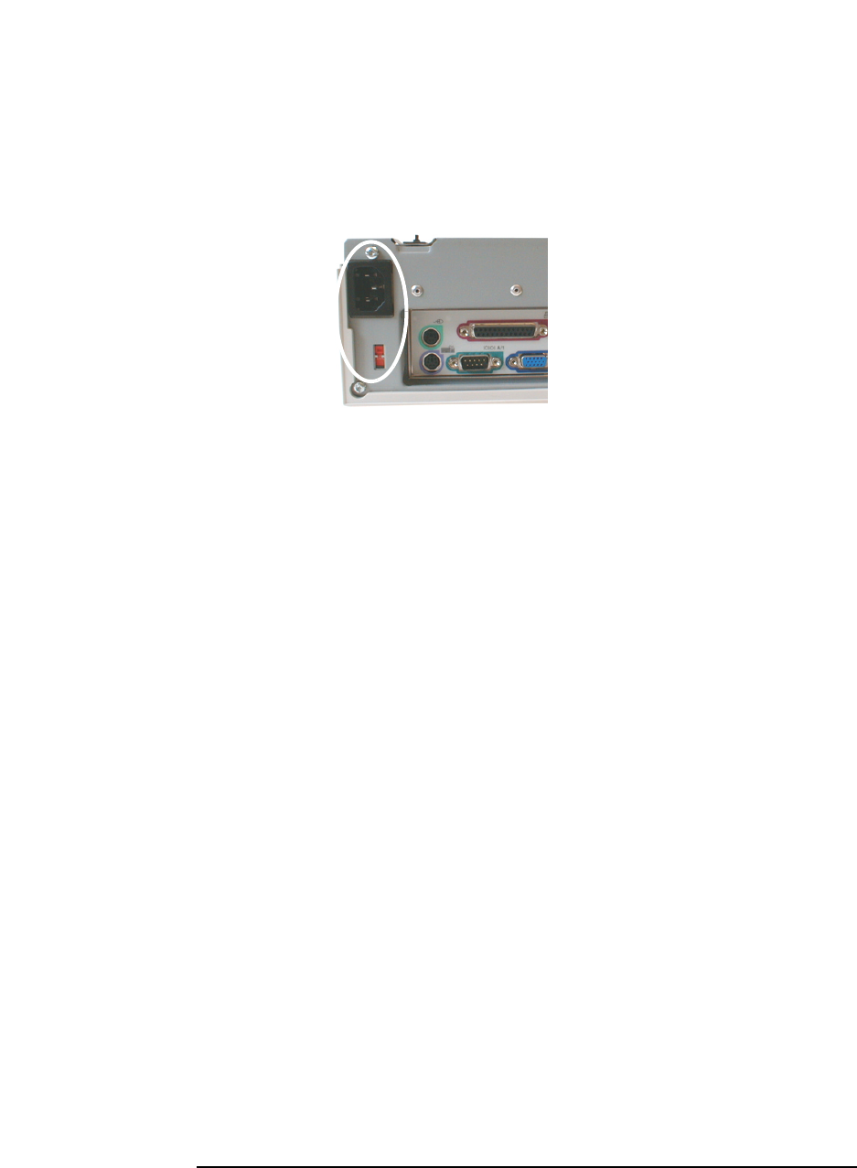
Rear view
Location of the voltage
switch and power connector
on the desktop.
Front view
On/Off power
button
Keyboard lock
status light (amber)
Disk activity light
(yellow) Power on
status light
(green)
11
1 System Overview
Package Features
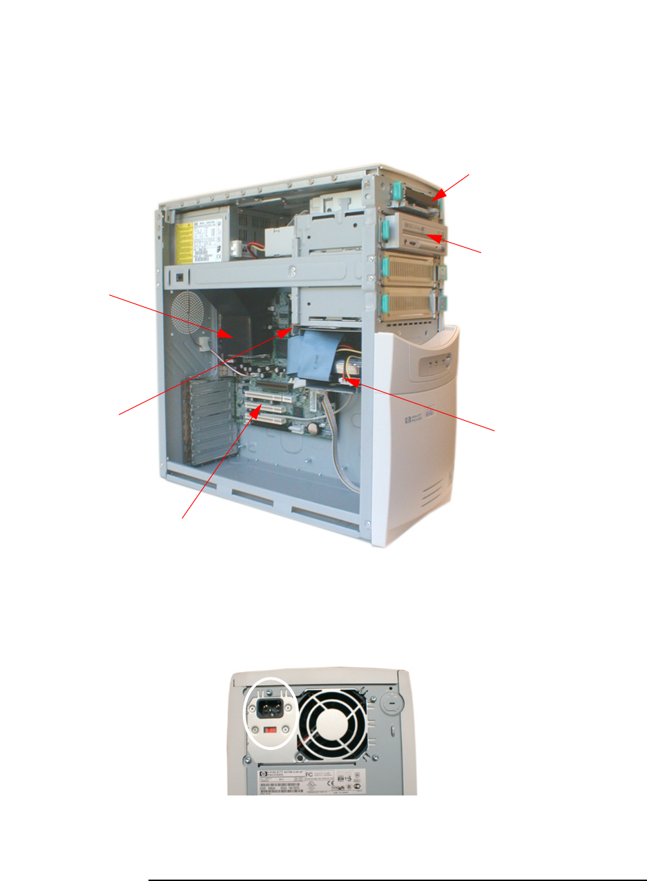
Inside the
Minitower
Main Memory
CD-ROM, CD-RW
drive, or DVD drive
Hard disk drive
Accessory board slots
Floppy disk drive
Processor
Rear view Location of the voltage
switch and power connector
on the minitower.
12
1SystemOverview
Package Features
Small Form Factor
Front panel
On/Off power button with
power on status light
Keyboard lock
status light (amber)
Disk activity light
(yellow)
Inside the Small
Form Factor Main Memory
CD-ROM, CD-RW
drive, or DVD drive
Hard disk drive
Accessory board slots
Floppy disk drive
Processor
13
1 System Overview
Package Features
Rear view
Location of the voltage switch
and power connector on the
small form factor.
14
1SystemOverview
Specifications
Specifications
Physical Characteristics
As an ENERGY STAR partner, HP has determined that this product meets the
ENERGY STAR guidelines for energy efficiency (Windows 2000, Windows 98 and
Windows 95 only).
Low power consumption (4.8W in suspend mode) can be achieved when
Suspend to RAM is activated. This can be done with ACPI operating systems
only (Windows 98 and Windows 2000). To activate Suspend to RAM, enter
your BIOS Setup by pressing F2 during startup, then go to the Power menu
and make sure that the field SuspendtoRAMis set to enabled.
When Suspend to RAM is not activated, or if it is activated in non-ACPI
operating systems, the power consumption in suspend mode will be around
25W.
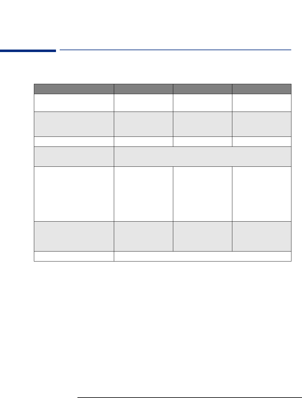
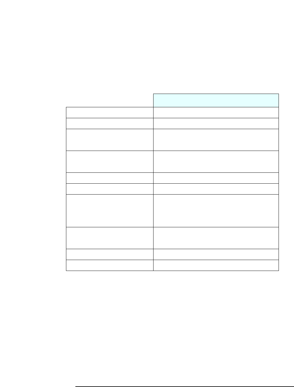
Characteristics VL400 Desktop PC VL400 Minitower PC VL400 SFFactor PC
Weight (configuration with 1 CD-ROM
drive, excluding keyboard and display)
10 kg (22 pounds) 13.4 kg (29.5 pounds) 8 kg (17.6 pounds)
Dimensions Width: 43.5cm (17.13in.)
Height: 13.5cm (5.32in.)
Depth: 43cm (16.93in.)
Width: 20.6cm (8.15in.)
Height: 46.9cm (18.46in.)
Depth: 45.5cm (17.9in.)
Width: 36.6cm (14.4in.)
Height: 10.1cm (3.98in.)
Depth: 40.7cm (16.14in.)
Footprint 0.187 m2(2.01 ft2)0.094m
2(1.01 ft2)0.15m
2(1.61 ft2)
Acoustic noise emission (IS O7779)
Operating (idle):
Sound power level LwA ≤3.5 BA (35 dBA)
Sound pressure level at the operator position LpA ≤26 dBA
Power Supply Input Voltage:
100-127 V 4A,
200-240V 2A ac
(voltage selection switch)
Input Frequency: 50/60 Hz
Maximum output power:
120W continuous
Input Voltage:
100-127 V 6A,
200-240V 3A ac
(voltage selection switch)
Input Frequency: 50/60 Hz
Maximum output power:
200W continuous
Input Voltage:
100-127 V 2500mA,
200-240V 1300mA ac
(voltage selection switch)
Input Frequency: 50/60 Hz
Maximum output power:
100W continuous
Power consumption
Typical:
SuspendtoRAM(ACPIs3):
115V/60Hz and 230V/50Hz
40 W
4.8 W
115V/60Hz and 230V/50Hz
40 W
4.8 W
115V/60Hz and 230V/50Hz
40 W
4.8 W
Storage Humidity 8% - 85% (relative), non-condensing at 40°C (104°F)
15
1 System Overview
Specifications
Environmental Specifications
Operating temperature and humidity ranges may vary depending upon the
mass storage devices installed. High humidity levels can cause improper
operation of disk drives. Low humidity levels can aggravate static electricity
problems and cause excessive wear of the disk surface.
Notes Operating temperature and humidity ranges may vary depending on the mass storage devices
installed. High humidity levels can cause improper operation of disk drives. Low humidity ranges
can aggravate static electricity problems and cause excessive wear of the disk surface.
The power consumption and acoustics figures given in the tables above are valid for the standard
configuration as shipped. For more information, refer to the product’s data sheet at HP’s web
site: www.hp.com/desktop
When the computer is turned off with the power button on the front panel, the power
consumption falls below 3W, but it is not zero. The special on/off method used by these
computers considerably extends the lifetime of the power supply. To reach zero power
consumption in “off” mode, either unplug the power outlet or use a power block with a switch.
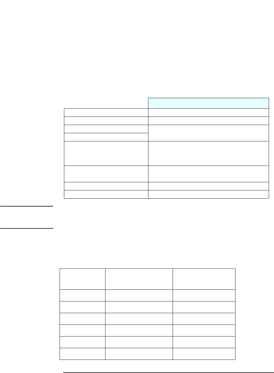
Environmental Specifications (System Processing Unit, with Hard Disk)
Operating Temperature +10°C to +35°C (+ 50°F to 95° F)
Storage Temperature -40°F to +70°F (-40°C to +158°C)
Operating Humidity 15% to 80% (relative)
Storage Humidity 8% to 85% (relative), non-condensing at 40°C (104°F)
Operating Altitude 10000 ft (3100m) max
Storage Altitude 15000ft (4600m) max

16
1SystemOverview
Specifications

2
System Features
This chapter describes core components of the PC such as processors,
chipsets, mass storage devices, graphics controllers, audio controllers,
network features and input devices.
18
2 System Features
VL400 System Board Layout
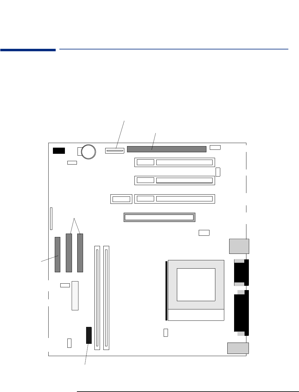
VL400 System Board Layout
All HP Vectra VL400 PC system boards have a Socket 370 for a compatible
Celeron or Pentium III processor.
System Board
DIMM1
DIMM2
System Board
switches
Main
memory
slots
Status panel
connector
Floppy connector
IDE
connectors
Power supply connector
PCI Slot 2
PCI Slot 3
PCI Slot 1 (DT + MT), or
Riser card slot (SFF)
AGP Slot (For AGP card or integ.
graphics memory extension)
Power protection
device connector
System Fan connector
(usedinSFF)
CD audio conn.
Chassis
intrusion conn.
WOL (Wake On
LAN) conn.
Battery Socket
Processor
socket
Active heatsink
fan connector
Data conn. for ISA extension kit
Power conn. for ISA extension kit
Internal speaker conn.
Power supply fan connector
(usedinMT+DT)
Parallel
Serial
VGA
Serial
Microphone-in
Line-in
Line-out
Keyboard
Mouse
LAN
2xUSB

19
2SystemFeatures
VL400 System Board Layout
PCI Mapping
VL400 PCI Mapping Table
Bus Device PCI Device Slot#
0 0 GMCH: Host bridge
0 2 GMCH: AGP bridge
0 30 ICH: Hub interface to PCI bridge
0 31 ICH: PCI to LPC bridge
0 31 ICH: IDE controller
0 31 ICH: USB controller
0 31 ICH: SMBUS controller
0 31 ICH: AC97 audio controller
12PCIslot1 1
11PCIslot2 2
10PCIslot3 3
20AGPdevice AGPslot
20
2 System Features
Architectural View
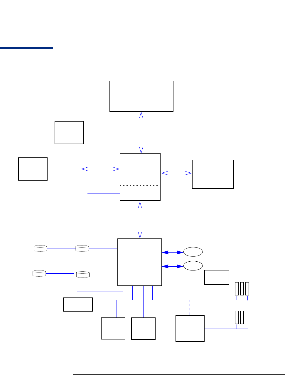
Architectural View
This block diagram applies primarily to Desktop and Minitower configurations.
ICH1 chip
Audio
CS4299
Processor
Celeron orPentium III
Intel 815 Main Memory
133MHz SDRAM
3 PCI Slots
2 ISA Slots
Memory Bus
Host Bus
AGP Bus
PCI Bus
ISA Bridge on
ISA extension
kit
Super I/O
Serial (2)/Parallel/FDD/PS2
Flash BIOS
Hard Disk
CD-ROM
2IDEDrives
DVD/CD-RW/Zip
Hard Disk
USB 1
USB2
2UATA66Disks
Integrated 815
graphics controller
AGP Slot
VGA Connector
AIMM graph-
ics memory
extension
AGP graphics
card (some DT,
MT models)
3COM
3C320 LAN

21
2SystemFeatures
Main Memory
Main Memory
There are two 168-pin DIMM slots on the system board for installing main
memory. You can install 133MHz SDRAM modules. These are available in 64,
128, 256 and 512 MB memory modules. You can install only one 512 MB
module. A maximum of 512 MB is supported.
You can use ECC or non-ECC memory modules. However, single/multiple bit-
error processing is not done by the 815 chipset.
Processors
The VL400 is equipped with either a single Socket 370 Intel Celeron or socket
370 Intel Pentium III processor. Socket 370 is a conversion of Slot 1 (used
previously by Celerons and Pentium IIs) to a socket, running at the same bus
protocol as the Pentium II (the GTL+ bus protocol). The processor is
connected to the system board through a Plastic Pin Grid Array (PPGA) 370
Socket. The reduction in size achieved by the Socket 370 Celeron is due to
the integration of the L2 cache on the processor die. Like the Celeron
processor, the Pentium III comes in a 370-pin socket (PGA370) package.
To find out more about Socket 370 Celeron technology, refer to the Tech ni cal
Reference Manual - Vectra Technology.
22
2 System Features
Mass Storage Devices
Mass Storage Devices
Hard Disk Drives
A 3.5-inch hard disk drive is supplied on an internal shelf in some models.
These hard drives can be provided with the PC. To see which other hard disk
drives can be purchased as accessories for the VL400, refer to www.hp.com/
go/pcaccessories.
To find out about Ultra-ATA DMA/ 66 hard disk drive technology, refer to the
Technical Reference Manual - Vectra Technology.
Floppy Disk Drives
All models are supplied with a 3.5-inch floppy disk drive.
CD-ROM and DVD Drives
Modelsmaybefittedwitha48✕Max IDE CD-ROM drive. It can play standard
CD-ROM discs, conforming to optical and mechanical standards as specified
in the Red and Yellow Book. This drive can also be purchased as an accessory.
Refer to www.hp.com/go/pcaccessories.
To find out about CD-ROM and DVD drive technology, refer to Technical
Reference Manual - Vectra Technology.
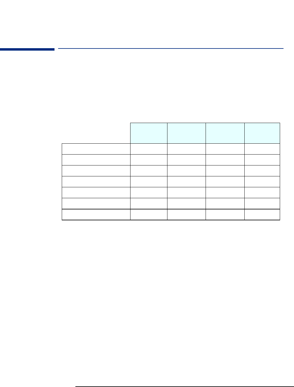
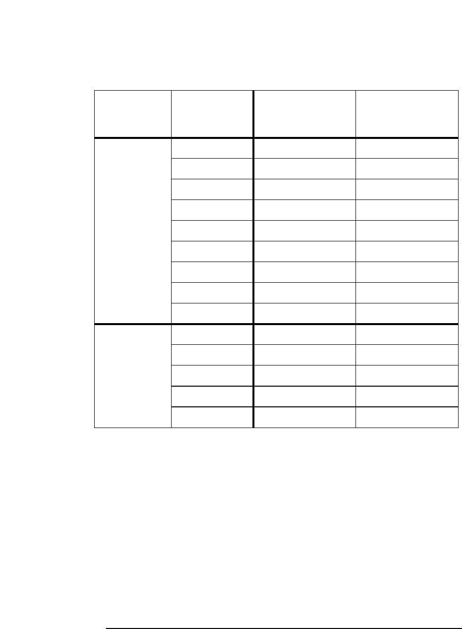
10 GB
Ultra-ATA 66
15 GB
Ultra-ATA 66
30 GB
Ultra-ATA 66
9.1 GB
Ultra-SCSI
Typical Seek Times (ms)
Average 9.5 8.5 <9.0 6.8
Track-to-Track 2.0 0.8 <1.0 0.9
Full Stroke 18.0 15.0 <20.0 15.0
Rotational Speed (RPM) 5 400 7 200 7 200 7 200
Internal Data Rate (Mb/s) Up to 194 235 191 to 298 Up to 257
Buffer Size (KB) Ultra ATA 512 512 2048 2048
23
2SystemFeatures
Mass Storage Devices
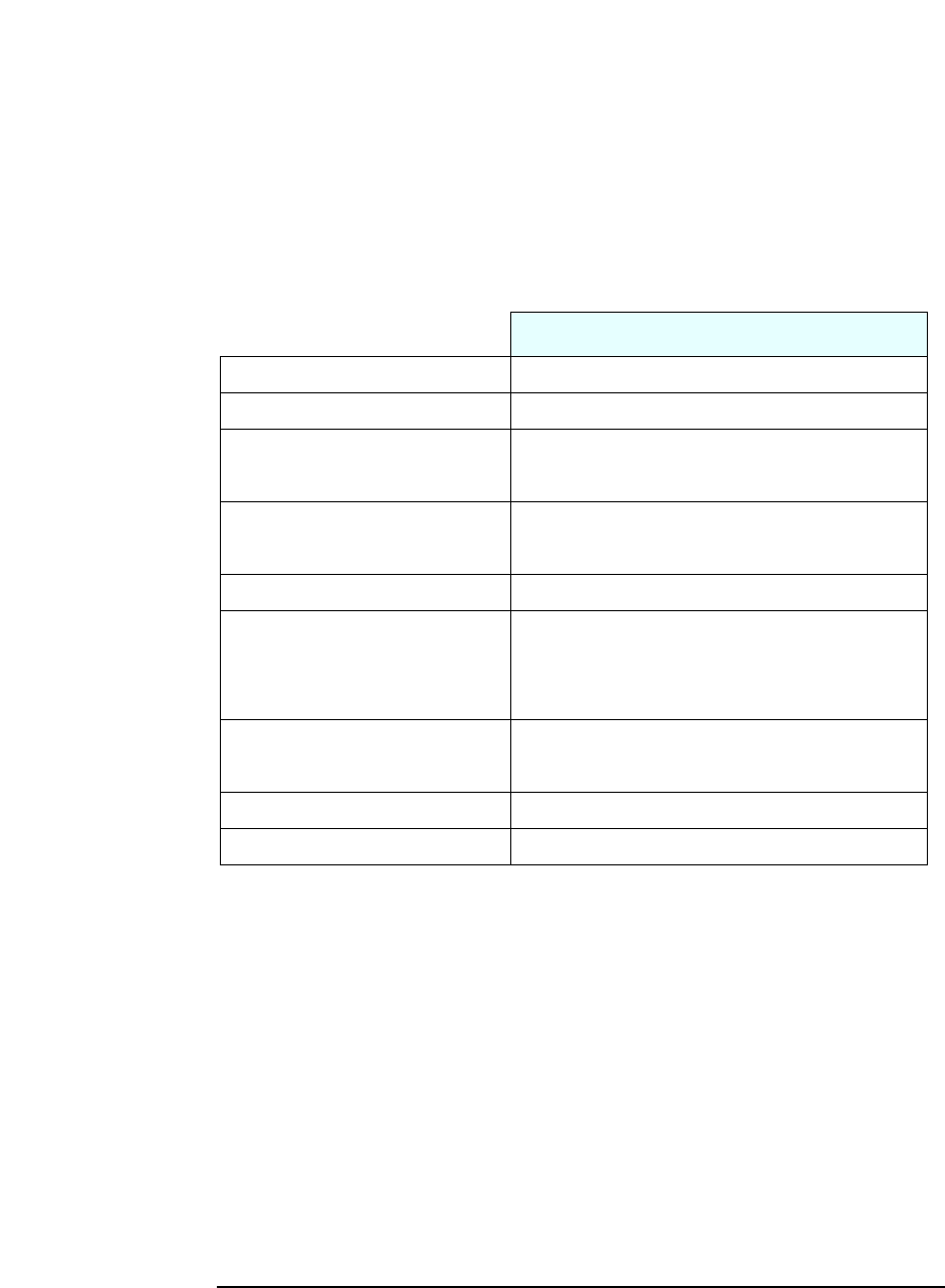
Features of the
CD-ROM Drive
(D9444A)
•CD-ROMMode-1datadisc.
• CD-ROM Mode-2 data disc (Mode 1 and Mode 2).
• Photo-CD Multisession.
• CD Audio disc.
• Mixed mode CD-ROM disc (data and audio).
• CD-ROM XA, CD-I, CD-Extra, CD-R, CD-RW.
Description
HP product number D9444A
Disc Diameter 120 mm
Data Block Size 2,055 bytes (14X, Mode-1)
4,800 bytes (32X, Mode-2)
Storage Capacity 650 Mbytes (Mode-1)
742 Mbytes (Mode-2)
Sustained Transfer Rate Outerside: 7,200 KB/s (48X)
Burst Transfer Rate PIO mode 4 - 16.6 Mbytes/s maximum
Single Word DMA Mode 2 - 8.3 Mbytes/s maximum
Multi Word DMA Mode 2 - 16.6 Mbytes/s maximum.
Access Time AverageStroke(1/3)110ms
Full Stroke 180 ms
Buffer Memory Size 128 kbytes
Rotational speed Approx. 11,100 rpm maximum
24
2 System Features
Mass Storage Devices
Features of the
CD-RW Drive
(D9524A)
• CD-ROM Mode-1 data disc.
• CD-ROMMode-2datadisc(Mode1andMode2).
• Photo-CD Multisession.
• CD Audio disc.
• Mixed mode CD-ROM disc (data and audio).
• CD-ROM XA, CD-I, CD-Extra, CD-R, CD-RW.
Description
HP product number D9524A
Disc Diameter 120 mm
Data Block Size 2,055 bytes (14X, Mode-1)
4,800 bytes (32X, Mode-2)
Storage Capacity 650 Mbytes (Mode-1)
742 Mbytes (Mode-2)
Write Mode 4X (CD-R) and 4X (CD-RW)
Read Mode Full CAV110.3X to 24X
Burst Transfer Rate PIO mode 4 - 16.6 Mbytes/s maximum
Single Word DMA Mode 2 - 8.3 Mbytes/s maximum
Multi Word DMA Mode 2 - 16.6 Mbytes/s maximum.
Access Time AverageStroke(1/3)110ms
Full Stroke 180 ms
Buffer Memory Size 128 kbytes
Rotational speed Approx. 7,300 rpm maximum
1.CAV = Constant Angular Velocity
25
2SystemFeatures
Mass Storage Devices
Features of the
DVD-ROM Drive
(D7521A)
•CD-ROMMode-1datadisc.
• CD-ROM Mode-2 data disc (Mode 1 and Mode 2).
• Photo-CD Multisession.
• CD Audio disc.
• Mixed mode CD-ROM disc (data and audio).
• CD-ROM XA, CD-I, CD-Extra, CD-R, CD-RW.
• DVD-ROM, DVD-Video, DVD Audio, DVD-RAM.
NOTE If a disk is still in the drive after power failure or drive failure, the disk can be
reclaimed by inserting a straightened paper-clip into the small hole at the
bottom of the door.
DVD Region Codes
TheDVD-ROMdriveisonlyabletoplayDVDvideodiscsfromregions1and2
(see table below). DVD region settings can be changed up to 5 times.
Description
HP product number D7521A
Disc Diameter 120 mm
Storage Capacity 650 MB to 17 GB (depending on disk type)
Read Mode 8Xmax(DVD),40XmaxCD-ROM
Burst Transfer Rate PIO mode 4 - 16.6 Mbytes/s maximum
Single Word DMA Mode 2 - 8.3 Mbytes/s maximum
Multi Word DMA Mode 2 - 16.6 Mbytes/s maximum.
Access Time Average Stroke (1 / 3) 110 ms
Full Stroke 180 ms
Buffer Memory Size 128 kbytes
Rotational speed Approx. 7,300 rpm maximum
Region Codes Region Supported by the
D4388A DVD Drive
1 USA & Canada Yes
2 Europe & Japan Yes
3 South East Asia No
4 Latin America & Australia No
5 Russia, Rest of Asia, Africa No
6 China No

26
2 System Features
Integrated Graphics Controller
Integrated Graphics Controller
Some models use the integrated Intel® 815 graphics controller for 2D and 3D
graphics. The Intel® 815 graphics controller uses Direct AGP and Dynamic
Video Memory technology.
The controller uses 9-10 MB of system memory for graphics purposes. You
can also install a 4 MB graphics memory extension (in the AGP slot) for a
total of 12 MB memory (8 MB system memory is used in this case). The 4 MB
memory extension can improve 2D and 3D graphics performance
significantly.
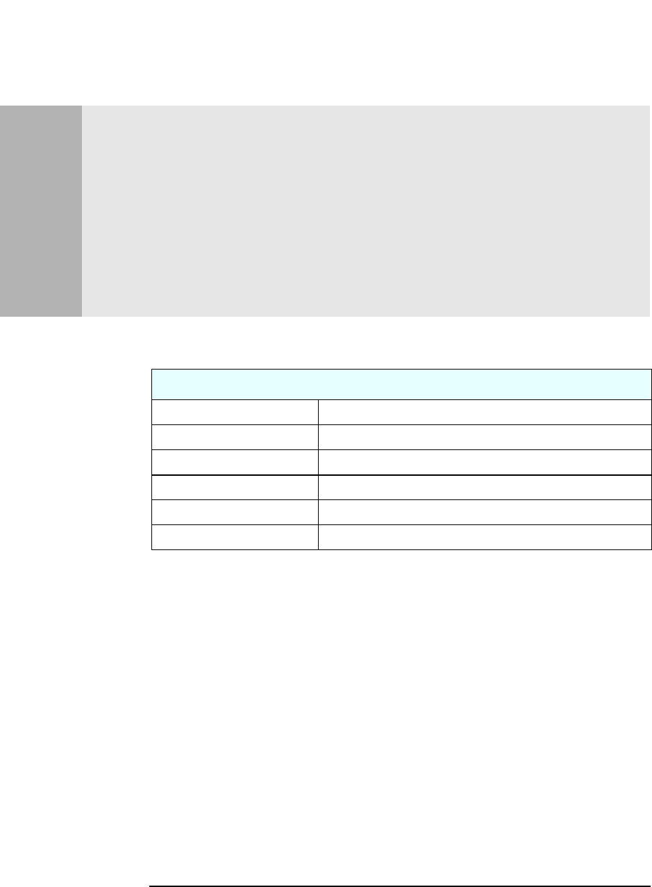
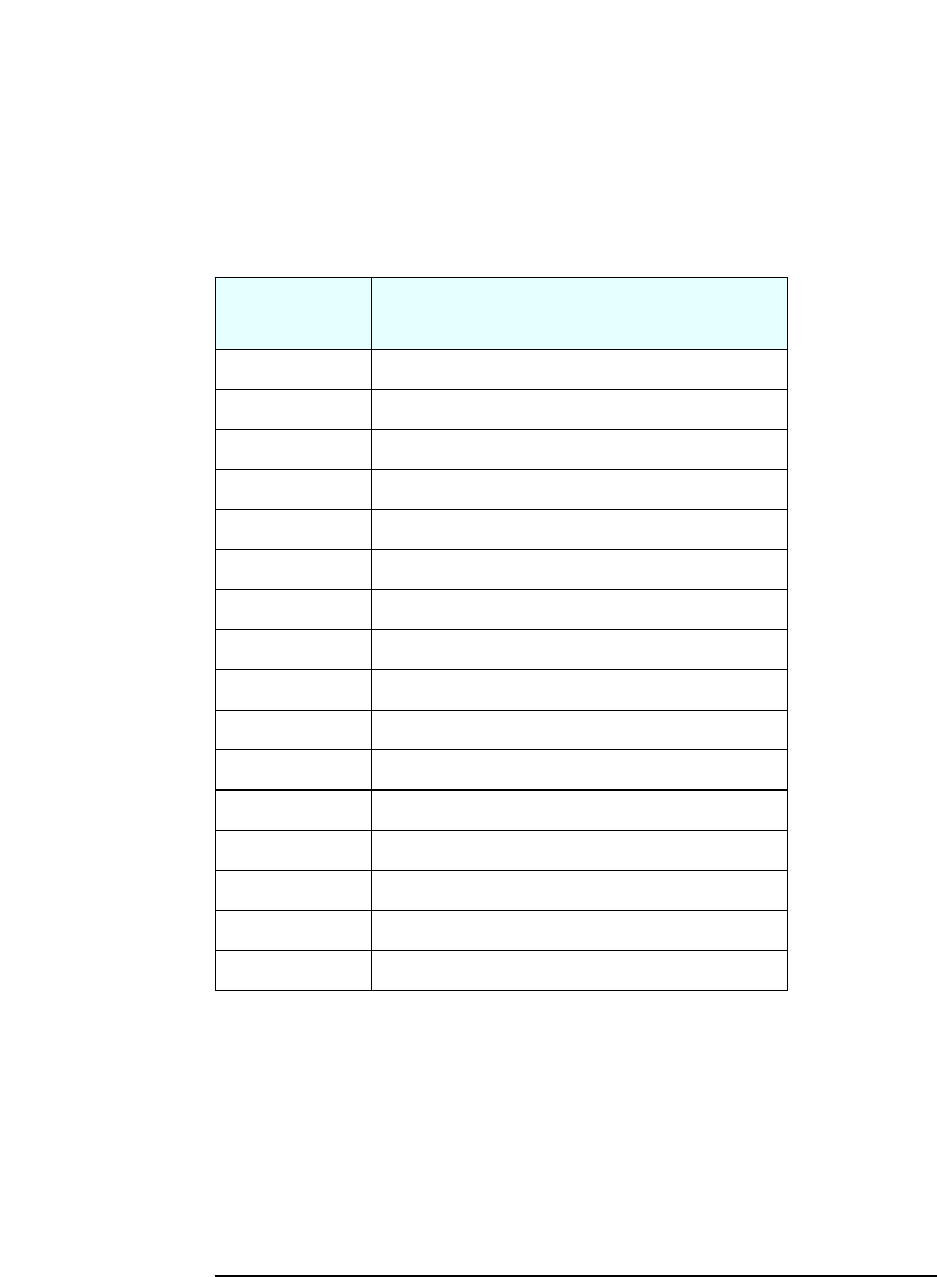
Supported Resolutions
The following non-interlaced resolutions are supported:
Mode Colors Refresh
640 x 480 256 60, 70, 72, 75, 85
640 x 480 65K 60, 70, 72, 75, 85
640 x 480 16.8M 60, 70, 72, 75, 85
800 x 600 256 60, 70, 72, 75, 85
800 x 600 65K 60, 70, 72, 75, 85
800 x 600 16.8M 60, 70, 72, 75, 85
1024 x 768 256 60, 70, 75, 85
1024 x 768 65K 60, 70, 75, 85
1024 x 768 16.8M 60, 70, 75, 85
1152 x 864 256 60, 70, 72, 75, 85
1152 x 864 65K 60, 70, 72, 75, 85
1152 x 864 16.8M 60, 75, 85
1280 x 1024 256 60, 70, 72, 75, 85
1280 x 1024 65K 60, 70, 72, 75, 85
1280 x 1024 16.8M 60, 70, 75, 85
1600 x 1200 256 60, 70, 72, 75
27
2SystemFeatures
Integrated Graphics Controller
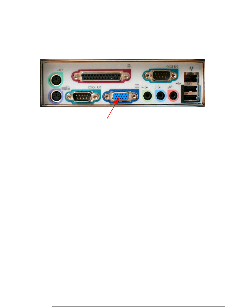
Connectors
A 15-pin VGA DB connector is located on the rear panel of the PC.
15-pin VGA DB Monitor Connector
This connector is disabled if the PC has an AGP graphics
card. In this case, use the graphics card’s connector.

28
2 System Features
Matrox Millennium G450 AGP 4X or PCI Graphics Card
Matrox Millennium G450 AGP 4X or PCI Graphics Card
Some Vectra VL400 PC models are supplied with a Matrox Millennium G450
AGP 4X graphics controller. Also, there is a PCI version of this graphics card
available for the VL400 Small Form Factor.
The Matrox Millennium G450 is a very high performance 2D/3D graphics
card.
For more information, refer to the Technical Reference Manual - HP Vectra
Technology available in PDF (Acrobat) format from www.hp.com/go/
vectrasupport.
Key Features
•Dual monitor output
•TV-out encoder
•64-bit Double Data Rate (DDR) memory interface
•Maximum resolution:
On main display, 2048 × 1536, true color at 85 Hz.
On second display, 1600 × 1200, true color at 85 Hz.
•Environment-Mapped Bump Mapping for greater 3D realism
•VCQ2 rendering for improved color and text
•3D Rendering Array Processor for fast, advanced 3D graphics
• 256-bit DualBus graphics chip
• AGP 4X host interface with 1GB/s bandwidth and Symmetrical Rendering
Architecture
• High-speed 360 MHz RAMDAC with ultra sharp image quality. Provides fast
screen refresh to eliminate screen flicker
•Second RAMDAC at 200MHz
•16 MB video memory (non-upgradeable).
29
2SystemFeatures
Matrox Millennium G450 AGP 4X or PCI Graphics Card
Maximum Supported Refresh Rates
A
AA
As
ss
sp
pp
pe
ee
ec
cc
ct
tttR
RR
Ra
aa
at
ttti
iiio
oo
oD
DD
Di
iiis
ss
sp
pp
pl
llla
aa
ay
yy
yR
RR
Re
ee
es
ss
so
oo
ol
lllu
uu
ut
ttti
iiio
oo
on
nn
n
M
MM
Ma
aa
ai
iiin
nn
nD
DD
Di
iiis
ss
sp
pp
pl
lllay
ayay
ay
3
33
36
66
60
00
0M
MM
MH
HH
Hz
zz
zR
RR
RA
AA
AM
MM
MD
DD
DA
AA
AC
CC
C
H
HH
Ho
oo
or
rrri
iiiz
zz
zo
oo
on
nn
nt
ttta
aa
al
lll/
///V
VV
Ve
ee
er
rrrt
ttti
iiic
cc
ca
aa
al
lll
S
SS
Se
ee
ec
cc
cond
ondond
onda
aa
ar
rrry
yy
yD
DD
Di
iiis
ss
sp
pp
pl
llla
aa
ay
yy
y
2
22
20
00
00
00
0M
MM
MH
HH
Hz
zz
zR
RR
RA
AA
AM
MM
MD
DD
DA
AA
AC
CC
C
H
HH
Ho
oo
or
rrri
iiiz
zz
zon
onon
ont
ttta
aa
al
lll/
///V
VV
Ve
ee
er
rrrt
ttti
iiic
cc
ca
aa
al
lll
4
44
4:
:::3
33
3/
///5
55
5:
:::4
44
4
S
SS
St
ttta
aa
and
ndnd
nda
aa
ar
rrrd
dd
d
640 x 480 130kHz / 200Hz 130kHz / 200Hz
800 x 600 130kHz / 200Hz 130kHz / 200Hz
1024 x 768 130kHz / 160Hz 130kHz / 160Hz
1152 x 864 130kHz / 140Hz 125kHz / 140Hz
1280 x 1024 130kHz / 120Hz 110kHz / 100Hz
1600 x 1200 130kHz / 100Hz 90kHz / 70Hz
1800 x 1440 130kHz / 85Hz —
1920 x 1440 130kHz / 85Hz —
2048 x 1536 130kHz / 85Hz —
1
11
16
66
6:
:::9
99
9/
///1
11
16
66
6:
:::1
11
10
00
0
W
WW
Wi
iiid
dd
de
ee
eS
SS
Sc
cc
cr
rrree
eeee
een
nn
n
856 x 480 130kHz / 200Hz 130kHz / 200Hz
1280 x 720 130kHz / 160Hz 110kHz / 120Hz
1600 x 1024 130kHz / 120Hz 90kHz / 85Hz
1920 x 1090 130kHz / 110Hz —
1920 x 1200 130kHz / 100Hz —
30
2 System Features
Audio
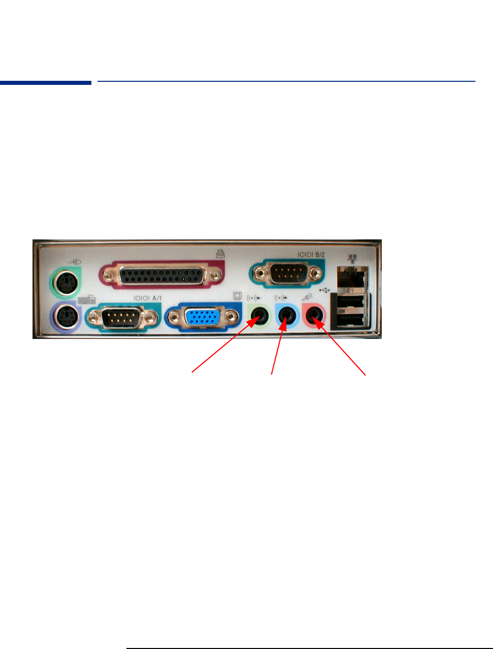
Audio
The Crystal®integrated PCI audio solution (not upgradeable) in your PC is a
CrystalClear™CS4299 Audio Codec ‘97 version 2.1. The CS4299 interfaces
directly with the South Bridge chip and performs all digital operations, such
as sample rate conversions and synthesis, as well as mixing and processing all
the analog signals.
All models have a Line In jack, Line Out jack and Mic In jack connector
located on the rear panel. These external jacks are standard connectors.
Adding an Audio
Accessory Board
The integrated PCI audio can be disabled in the Advanced menu of the Setup
program, if an audio accessory board is installed.
For more information on audio technology, refer to the Technical Reference
Manual - Vectra Technology.
Line out / speaker
connector Microphone
connector
Line in connector
31
2SystemFeatures
Network
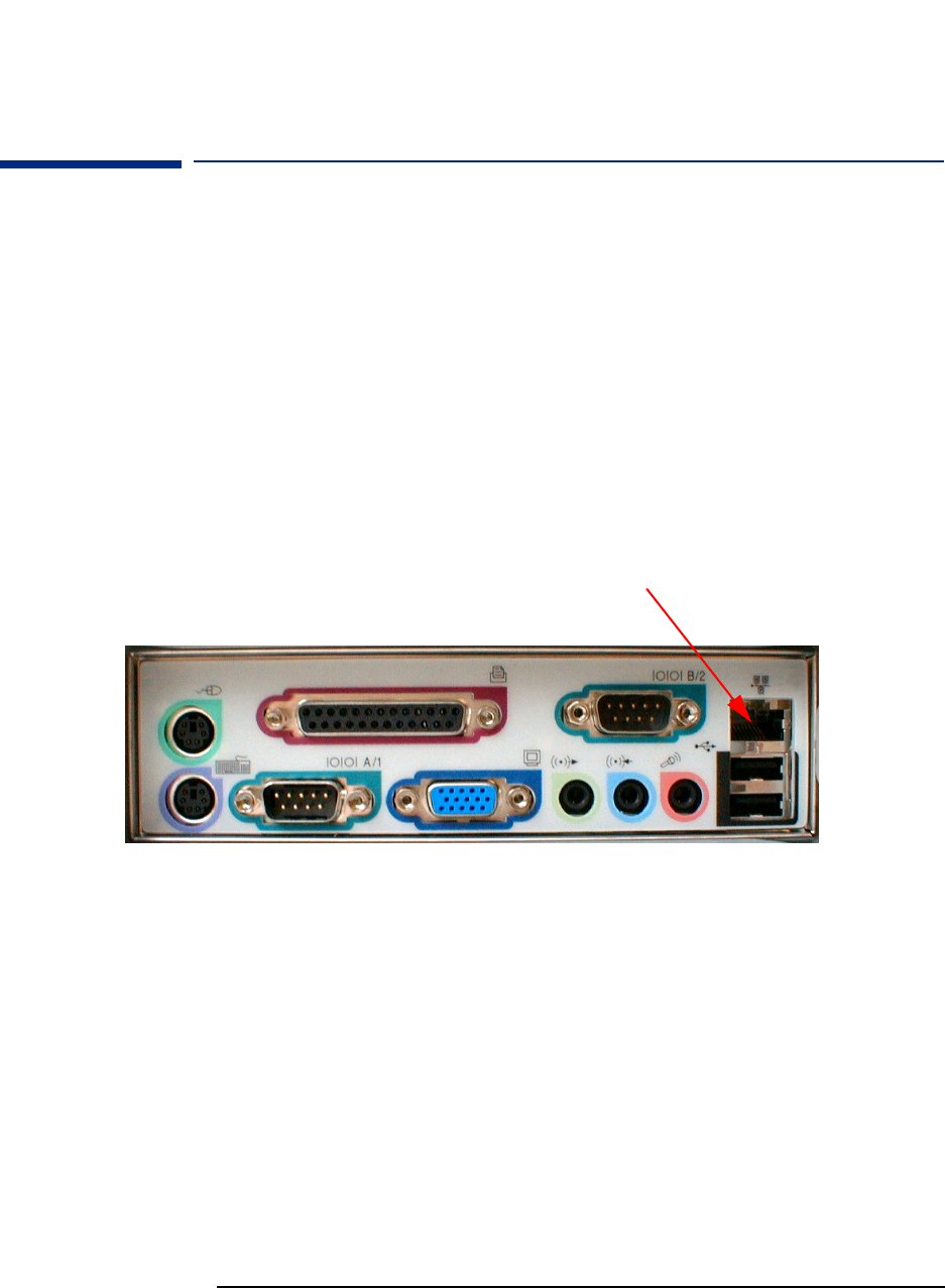
Network
All models have an integrated 3COM 3C920 Fast Etherlink 10/100 Base-TX
LAN controller.
The integrated 3COM 3C920 is a full duplex LAN controller with automatic
10/100 BT port selection. It supports both AMP and ACPI power management
features, such as WOL (Wake On LAN).
If you install a LAN card, you can disable the integrated LAN controller in the
PC’s Setup program.
Connectors The 10/100BT connector is located on the rear of the PC.
10/100BT LAN connector
32
2 System Features
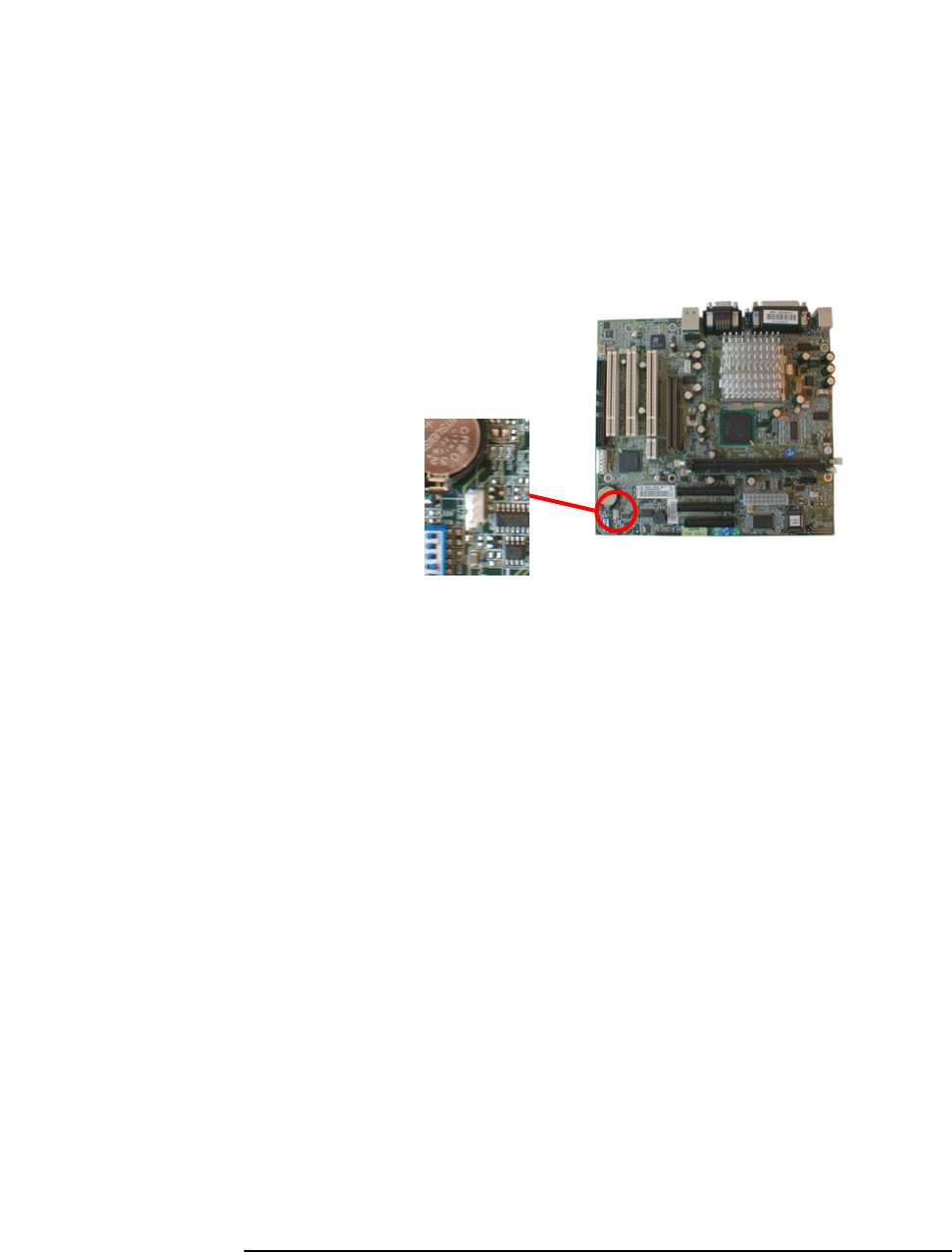
Network
A Wake On LAN (WOL) connector is located on the system board as shown
here. It is not required for PCI 2.2-compliant LAN cards such as the 3Com
3C905CTX LAN card but can be useful for other cards for Remote Wake Up
(inatokenringenvironmentforexample).
For more information on network technology, refer to the Technical
Reference Manual - Vectra Technology.
WOL
Connector

33
2SystemFeatures
Accessory Boards
Accessory Boards
The VL400 has four accessory board slots: three PCI slots and one AGP slot
(refer to the system board diagram on page 18 for their location). In the
minitower and desktop, you can also install the HP Two ISA Slot Extension Kit
(available as an accessory) for two ISA slots.
Some models have a high-end graphics card installed in the AGP slot.
Small Form Factor PCs In the VL400 SF, the PCI slots on the system board are not used for accessory
boards. Instead, there is a riser card installed in the special PCI-riser slot. The
standard riser card provides 3 PCI slots. An alternative riser card is also
available that provides one PCI slot and one combo PSI-ISA slot.
PCI Slot Numbers Your PC uses logical slot numbers in the BIOS Setup program. You need to
know these logical slot numbers if you want to change the PCI slot
configuration in the Setup program (refer to the system board diagram on
page 18 for their location). PCI slot numbers are also indicated on the system
board itself.

34
2 System Features
Accessory Boards

3
Serviceability
This chapter introduces the enhanced serviceability features of the
HP Vectra VL400 PC. It shows how easily you can open the PC and remove
or add system components using the serviceability features developed for
these PC models.
36
3 Serviceability
VL400 Desktop
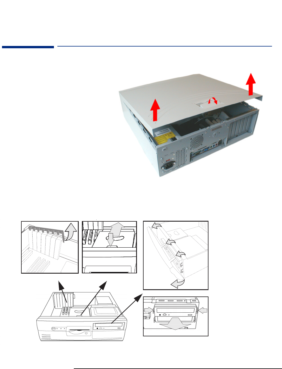
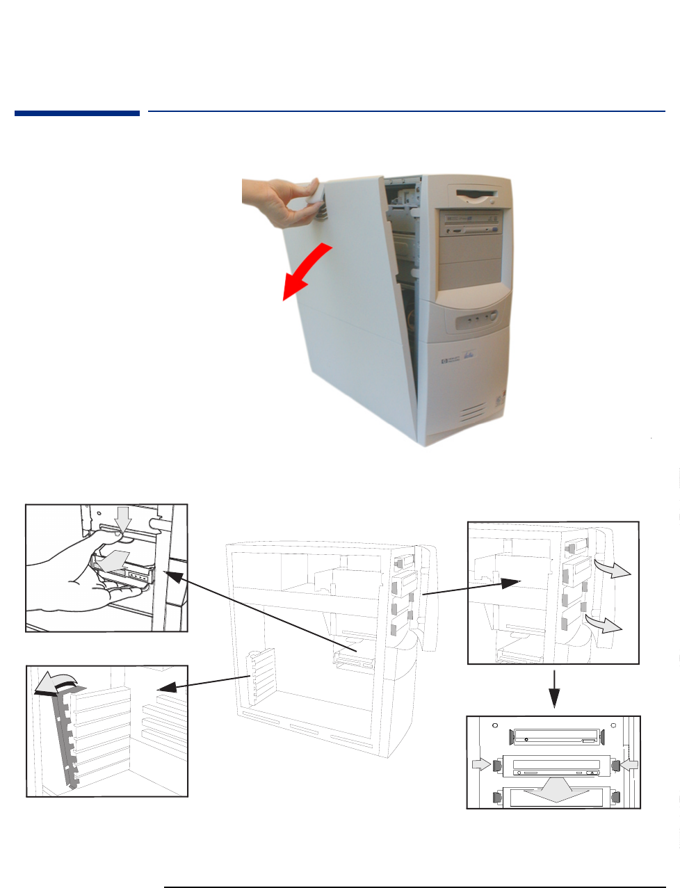
VL400 Desktop
1
1
1
2
2
11
1
2
EXPANSION CARDS HARD DISK / FLOPPY
CD / DVD
????????????????? ????? ???????????????????? ??????
Shows how to remove the
retaining clip
Shows how to remove
the drive bay
Shows how to remove
theDVD,CD-RW,orCD-
ROM drive
Shows how to remove
the front panel
Removing the cover
37
3 Serviceability
VL400 Minitower
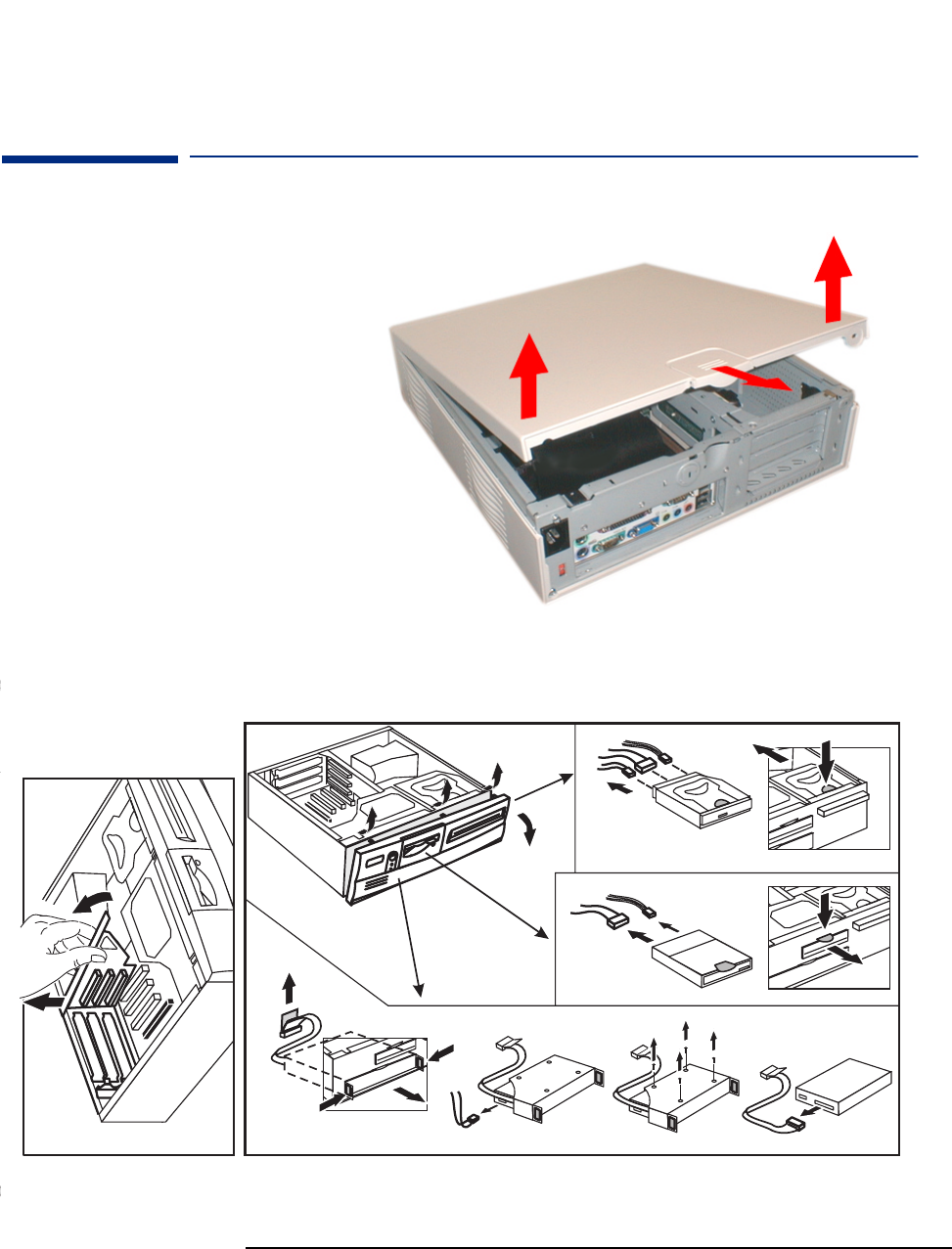
VL400 Minitower
1
2
2
11
CD / DVD / FLOPPY
EXPANSION CARDS
HARD DISK
??????? ????? ?? ????? ???? ? ????????? ???? ??? ???? ???? ??
Shows how to remove the
retaining clip
Shows how to remove
the hard disk
Shows how to remove the DVD,
CD-RW, or CD-ROM drive
Shows how to remove
the front panel
Removing the cover
38
3 Serviceability
VL400 Small Form Factor
VL400 Small Form Factor
Floppy
CD
Hard Disk Drive
service-label.fm Page 1 Thursday, March 23, 2000 10:40 AM
Removing the cover
Shows how to remove the front panel
Shows how to remove the hard disk drive
Shows how to remove the DVD, CD-RW,
or CD-ROM drive (top) and floppy drive
(middle)
Shows how to remove the
accessory board bracket

4
BIOS Overview
This chapter describes the BIOS features for the HP Vectra VL400 PC
models.

40
4 BIOS Overview
BIOS Summary
BIOS Summary
HP Vectra VL400 PCs contain a Phoenix BIOS (Basic Input Output System),
which was customized by Phoenix for use on the VL400. The system ROM
contains the POST (power-on self-test) routines, and the BIOS: the System
BIOS, video BIOS, and 3Com LAN boot ROM.
The system BIOS is identified by the version number IP.xx.xx.Thelatest
BIOS version for your PC and instructions for updating the BIOS can be
downloaded from the HP’s Support Web site at:
www.hp.com/go/vectrasupport.
This section covers:
• The BIOS Setup program
•Powersaving
• BIOS addresses
• The order in which POST tests are performed
• Beep codes.
Using the HP Setup Program
Press F2 to run the Setup program, when the HP logo is displayed
immediately after restarting the PC.
Press F8 to enter the Boot menu. Use the boot menu to select the order of
the devices the PC will use to start (boot) from.
Press F12 to boot (start) on the network. This option will only work if your
PC and the network is configured correctly.
Alternatively, press Esc to view the summary configuration screen. By
default, this remains on the screen for 20 seconds, but by pressing the Pause
key once, it can be held on the screen indefinitely until any key is pressed.
The Setup screen offers five menus: Main, Advanced, Security, Boot, Power
and Exit. These are selected using the left and right arrow keys.
Help Information
The HP Setup Program provides detailed help information.To get help on
any field, simply highlight the chosen field using the keyboard arrow keys.
The right hand portion of the Setup window will provide help information for
that field.

41
4 BIOS Overview
BIOS Summary
Main Menu
The Main Menu contains the following fields:
•Systemdate
•Systemtime
•BIOSversion
•CPUType
• CPU Speed
•CacheRAM
•BaseMemory
• Extended Memory
TheMainMenualsocontainstheKeyboard Features sub-menu, which
enables you to set Numlock and auto-repeat features.
Advanced Menu
The Advanced menu contains the following fields:
•CPUBusRatio
• Plug & Play O/S
• Reset Configuration Data
• Memory Hole at 15M-16M
• Processor serial number
These additional fields can be used to disable the integrated facilities (useful
when you install an accessory card that performs these functions):
• Integrated USB Interface
• Integrated Network Interface
• Integrated Audio Interface
The Advanced menu also contains the following sub-menus:
•Cache Options. To set the state of the processor memory cache.
•Flexible Disk Drives. To set the on-board floppy disk drive configuration.
•IDE Devices. Configure IDE Primary and Secondary devices.
•Video Options. To configure video options, such as which video controller
to use.
•Integrated I/O Ports. Configure, enable or disable the on-board parallel
and serial ports.
•PCI Configuration. Configure a specific PCI device.

42
4 BIOS Overview
BIOS Summary
•CPU Microcode Update. To update the CPU microcode. You must have
Administrator rights to use this facility.
Security
There are sub-menus for changing the characteristics and values of the
system administrator password, user password, Hardware Protection and
Boot Device Security, the amount of protection against the system’s drives
and network connections, and the amount of protection for booting from the
system’s drives and network connections.
The Security Menu contains the following sub-menus:
•User and Administrator Password.
The user password can only be set when an administrator password has
been set. The user password prevents unauthorized use of the computer,
protects stored data.
The administrator password prevents unauthorized access to the
computer’s configuration. It can also be used to start the computer.
•Hardware protection. Allows you to enable, disable or write protect the
following devices: hard disk, parallel port, serial ports, and boot sector.
Write protect helps to prevent users from copying confidential data (to
floppy disk for example).
•Boot Devices Security. Allows you to prevent or authorize users from
booting from devices such as the network, CD-ROM, floppy disk, and hard
disk.
Protection Against
Viruses
The VL400 has several features to protect it from viruses:
• Hard Drive Master Boot Sector Protection: It is impossible to write on the
boot sector or to format the hard disk when this feature is enabled. This
protection is enabled in the Security -Hardware protection menu of the
Setup program.
• PC Boot Block Protection: The boot block is protected by a physical switch
on the system board (switch 4) and a software switch. When flashing the
BIOS, the switch must be closed; HP’s BIOS flash program closes the
software switch before flashing the BIOS.
• BIOS Flash Protection: BIOS flashing is protected by two software
switches.

43
4 BIOS Overview
BIOS Summary
Boot Menu
The QuickBoot Mode option allows the system to skip certain tests while
booting. This decreases the time needed to boot the system.
The Boot-time Diagnostics screen enables the user to display either the HP
logo or diagnostic’s screen during POST.
Boot Device Priority allows you to select the order of the devices from which
the BIOS attempts to boot the operating system. During POST, if the BIOS is
unsuccessful at booting from one device, it will then try the next one on the
list until an operating system is found.
Hard Disk Drives allows you to choose the hard drive you want to boot from.
Removable Devices allows you to choose which drive letters you want to
assign to removable devices.
Power Menu
The Power menu has the following fields:
•State After Power Failure. This field allows you to select the state that the
PC will place itself into after a power failure. For example, if you set this
field to Off, the PC will not start up after a power failure. Setting this value
to Auto means that the PC will return to the state it was in before the power
failure took place.
•Advanced Power Management (APM) fields. These fields allow you to set
APM features, such as the timeout before the PC goes into suspend mode,
and whether the PC will wake up (or power on) from modem or network
card activity.
•Advanced Configuration and Power Management (ACPI) field. It allows
you to enable or disable the Suspend to RAM feature available with ACPI
operating systems (such as Windows 2000).

44
4 BIOS Overview
Power Saving and Ergonometry
Power Saving and Ergonometry
Soft Power Down
Soft Power Down is available with the Windows NT operating system. If users
want to shut down their PC, they are able to do so directly from the Windows
NT interface. There is no longer any need to physically switch off the PC.
The hardware to do this is contained in the ICH chipset. This chipset is
described in detail in Technical Reference Manual - HP Vectra Technology.
Safe Off
Safe Off is available with the Windows 95 and Windows 98 operating systems.
If users attempt to shut down the operating system when an application is
open and has not been saved, they are requested to save their work before
the computer can be powered off.
In Windows 2000, the equivalent to HP’s Safe Off is provided by the operating
system.
The hardware to do this is contained in the ICH chipset. This chipset is
described in detail in Technical Reference Manual - HP VectraTechnology.
Power Management
You can reduce the PC’s overall power consumption by using Power
Management to slow down the PC’s activity when it is idle.
Operating System Power Management
Operating systems such as Windows 98 SE, Windows NT 4.0 and Windows
2000 differ in their power management capabilities. Refer to your operating
system documentation for more information.
APM Power Management Modes
• Suspend
In Windows 95 for example, you can enter this low power state by clicking
Start Suspend. You can also set the timeout value (time of inactivity
before going into Suspend mode) in the PC’s Setup Program. In this mode,
the LED on the PC’s font panel blinks green.

45
4 BIOS Overview
Power Saving and Ergonometry
ACPI Power Management Modes (Windows 2000 and Windows98 SE only)
•Standby
In Windows 2000 for example, you can enter this low power state by
clicking Start Shut Down,thenselectingStand by and clicking OK.In
this mode, the LED on the PC’s font panel blinks green.
There are two forms of Standby: normal (s1) and Suspend to RAM (s3),
which is a lower power consumption state than normal Standby. You can
use Suspend to RAM by enabling this feature in the PC’s Setup Program.
To do this, press F2 during startup, then set Suspend to RAM in the Power
menu to enabled. If this feature is disabled, the normal (s1) Standby is
used.
•Hibernate(s4)
This is available in Windows 200 only and is lower power state than
Standby. In Windows 2000, you can enter this low power state by clicking
Start Shut Down, then selecting Hibernate and clicking OK.Inthis
mode, the LED on the PC’s font panel is off.

46
4 BIOS Overview
BIOS Addresses
BIOS Addresses
This section provides a summary of the main features of the HP system BIOS.
This is software that provides an interface between the computer hardware
and the operating system.
System Memory Map
Reserved memory used by accessory boards must be located in the area from
C8000h to EFFFFh.
HP I/O Port Map (I/O Addresses Used by the System)
Peripheral devices, accessory devices and system controllers are accessed via
the system I/O space, which is not located in system memory space. The 64
KB of addressable I/O space comprises 8-bit and 16-bit registers (called
I/O ports) located in the various system components. When installing an
accessory board, ensure that the I/O address space selected is in the free area
of the space reserved for accessory boards (100h to 3FFh).
0000 0000 - 0000 03FF Real-mode IDT
0000 0400 - 0000 04FF BIOS Data Area
0000 0500 - 0009 FC00 Used by OS
0009 FC00 - 0009 FFFF Extended BIOS Data Area
000A_0000 - 000B_FFFF Video RAM or
SMRAM (not visible unless in SMM)
000C 0000 - 000C 7FFF Video ROM
000C 8000 - 000F FFFF Adapter ROM, RAM, memory-mapped registers
000E 0000 - 000F FFFF System BIOS (Flash/Shadow)
10 0000 - FF FFFF Memory (1 MB to 16 MB)
100 0000 - 1FF FFFF Memory (16 MB to 32 MB)
200 0000 -3FF FFFF Memory (32 MB to 64 MB)
400 0000 -1FFF FFFF Memory (64 MB to 512 MB)
FFF80000 - FFFF FFFF 512 KB BIOS (Flash)

47
4 BIOS Overview
BIOS Addresses
Although the Setup program can be used to change some of the settings, the
following address map is not completely BIOS dependent, but is determined
partly by the operating system. Note that some of the I/O addresses are
allocated dynamically.
I/O Address Ports Function
0000 - 000F DMA controller 1
0020 - 0021 Master interrupt controller (8259)
002E - 002F NS364 Configuration registers
0040 - 0043 Timer 1
0060, 0064 Keyboard controller (reset, slow A20)
0061 Port B (speaker, NMI status and control)
0070 Bit 7: NMI mask register
0070 - 0071 RTC and CMOS data
0080 Manufacturing port (POST card)
0081 - 0083, 008F DMA low page register
0092 PS/2 reset and Fast A20
00A0 - 00A1 Slave interrupt controller
00C0 - 00DF DMA controller 2
00F0 - 00FF Co-processor error
0170 - 0177 IDE secondary channel
01F0 - 01F7 IDE primary channel
0278 - 027F LPT 2
02E8 - 02EF Serial port 4 (COM4)
02F8 - 02FF Serial port 2 (COM2)
0372 - 0377 IDE secondary channel, secondary floppy disk drive
0378 - 037A LPT1
03B0 - 03DF VGA
03E8 - 03EF COM3
03F0h- 03F5 Floppy disk drive controller
03F6 IDE primary channel
03F7 Floppy disk drive controller
03F8 - 03FF COM1
04D0 - 04D1 Interrupt edge/level control
0678 - 067B LPT2 ECP
0778 - 077B LPT1 ECP
0CF8 - 0CFF PCI configuration space

48
4 BIOS Overview
BIOS Addresses
DMA Channel Controllers
Only “I/O-to-memory” and “memory-to-I/O” transfers are allowed.
“I/O-to-I/O” and “memory-to-memory” transfers are disallowed by the
hardware configuration.
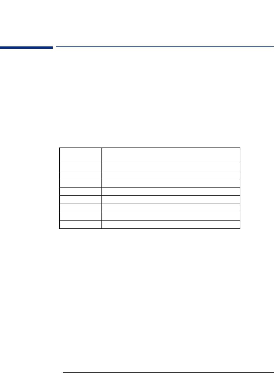
The system controller supports seven DMA channels, each with a page
register used to extend the addressing range of the channel to 16 MB. The following table
summarizes how the DMA channels are allocated.
DMA controller
Channel Function
0Free
1 Free if not used for parallel port in Setup
2 Floppy disk controller
3 Free if not used for parallel port in Setup
4 Used to cascade DMA channels 0-3
5Free
6Free
7Free
49
4 BIOS Overview
BIOS Addresses
Interrupt Controllers
The Interrupt Requests (IRQ) are numbered sequentially, starting with the master controller, and
followed by the slave.
PCI Interrupt Request Lines
PCI devices generate interrupt requests using up to four PCI interrupt
request lines (INTA#, INTB#, INTC#, and INTD#). PCI interrupts can be
shared; several devices can use the same interrupt. However, optimal system
performance is reached when minimizing the sharing of interrupts.
IRQ
(Interrupt Vector) Interrupt Request Description
INTR
IRQ0 System Timer
IRQ1 Keyboard Controller
IRQ3 Used by serial port if enabled
IRQ4 Used by serial port if enabled
IRQ5 Free if not used for parallel port or audio
IRQ6 Floppy Disk Controller
IRQ7 LPT1
IRQ8 RTC
IRQ9 Available for PCI devices, if not used by ISA board or USB port
IRQ10 Available for PCI devices, if not used by ISA board or USB port
IRQ11 Available for PCI devices, if not used by ISA board or USB port
IRQ12 Mouse
IRQ13 Co-processor
IRQ14 IDE Primary channel
IRQ15 IDE Secondary channel. Free unless disabled
50
4 BIOS Overview
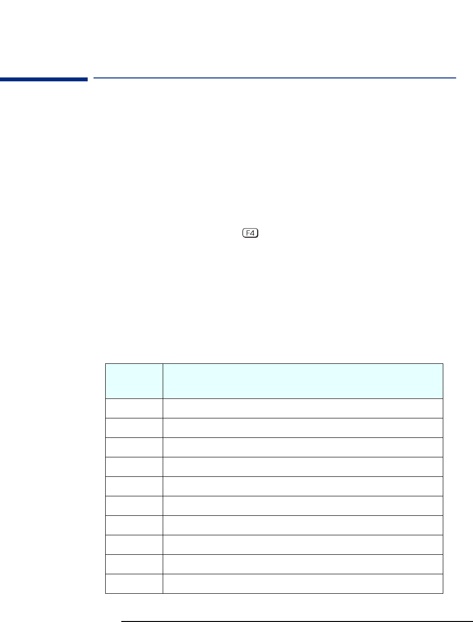
Order in Which the POST Tests are Performed
Order in Which the POST Tests are Performed
Each time the system is powered on, or a reset is performed, the POST is
executed. The POST process verifies the basic functionality of the system
components and initializes certain system parameters.
The POST starts by displaying a graphic screen of the Hewlett-Packard logo
when the PC is started.
Devices, such as memory and newly installed hard disks, are configured
automatically. The user is not requested to confirm the change. Newly
removed hard disks are detected, and the user is prompted to confirm the
new configuration by pressing . Note, though, that the POST does not
detect when a hard disk drive has been otherwise changed.
During the POST, the BIOS and other ROM data is copied into high-speed
shadow RAM. The shadow RAM is addressed at the same physical location as
the original ROM in a manner which is completely transparent to applications.
It therefore appears to behave as very fast ROM. This technique provides
faster access to the system BIOS firmware.
The following table lists the POST checkpoint codes written at the start of
each test.
Checkpoint
Code POST Routine Description
02h Verify Real Mode
03h Disable Non-Maskable Interrupt (NMI)
04h Get CPU type
06h Initialize system hardware
08h Initialize chipset with initial POST values
09h Set IN POST flag
0Ah Initialize CPU registers
0Bh Enable CPU cache
0Ch Initialize caches to initial POST values
0Eh Initialize I/O component

51
4 BIOS Overview
Order in Which the POST Tests are Performed
0Fh Initialize the local bus IDE
10h Initialize Power Management
11h Load alternate registers with initial POST values
12h Restore CPU control word during warm boot
13h Initialize PCI Bus Mastering devices
14h Initialize keyboard controller
17h Initialize cache before memory autosize
18h 8254 timer initialization
1Ah 8237 DMA controller initialization
1Ch Reset Programmable Interrupt Controller
24h Set ES segment register to 4 GB
26h Enable A20 line
28h Autosize DRAM
29h Initialize POST Memory Manager
2Ah Clear 512 KB base RAM
32h Test CPU bus-clock frequency
33h Initialize POST Dispatch Manager
34h Test CMOS RAM
35h Initialize alternate chipset registers
36h Warm start shutdown
37h Reinitialize the chipset (MB only)
38h Shadow system BIOS ROM
39h Reinitialize the cache (MB only)
3Ah Autosize cache
3Ch Configure advanced chipset registers
Checkpoint
Code POST Routine Description

52
4 BIOS Overview
Order in Which the POST Tests are Performed
3Dh Load alternate registers with CMOS values
40h Set initial CPU speed
42h Initialize interrupt vectors
44h Initialize BIOS interrupts
45h POST device initialization
47h Initialize manager for PCI Option ROMs (Rel. 5.1 and earlier)
48h Check video configuration against CMOS
49h Initialize PCI bus and devices
4Ah Initialize all video adapters in system
4Bh Display QuietBoot screen
4Ch Shadow video BIOS ROM
4Eh Display BIOS copyright notice
50h Display CPU type
51h Initialize EISA board
52h Test keyboard
54h Set key click if enabled
56h Enable keyboard
59h Initialize POST display service
5Ah Display prompt “Press F2 to enter SETUP”
5Bh Disable CPU cache
5Ch Test RAM between 512 and 640 KB
60h Test extended memory
62h Test extended memory address lines
64h JumptoUserPatch1
66h Configure advanced cache registers
Checkpoint
Code POST Routine Description

53
4 BIOS Overview
Order in Which the POST Tests are Performed
67h Initialize Multi Processor APIC
68h Enable external and CPU caches
69h Setup System Management Mode (SMM) area
6Ah Display external L2 cache size
6Ch Display shadow-area message
6Eh Display possible high address for UMB recovery
70h Display error messages
72h Check for configuration errors
74h Test real-time clock
76h Check for keyboard errors
7Ah Test for key lock on
7Ch Set up hardware interrupt vectors
7Eh Initialize coprocessor if present
80h Disable onboard Super I/O ports and IRQs
81h Late POST device initialization
82h Detect and install external RS 232 ports
83h Configure non-MCD IDE controllers
84h Detect and install external parallel ports
85h Initialize PC-compatible PnP ISA devices
86h Re-initialize onboard I/O ports
87h Configure Motherboard Configurable Devices
88h Initialize BIOS Data Area
89h Enable Non-Maskable Interrupts (NMIs)
8Ah Initialize Extended BIOS Data Area
8Bh Test and initialize PS/2
Checkpoint
Code POST Routine Description

54
4 BIOS Overview
Order in Which the POST Tests are Performed
8Ch Initialize floppy controller
8Fh Determine number of ATA drives
90h Initialize hard disk controllers
91h Initialize local-bus hard disk controllers
92h JumptoUsersPatch2
93h Build MPTABLE for multi-processor boards
94h Disable A20 address line (Rel. 5.1 and earlier)
95h Install CD ROM for boot
96h Clear huge ES segment register
97h Fixup Multi Processor table
99h Check for SMART drive
9Ah Shadow option ROMs
9Ch Set up Power Management
9Eh Enable hardware interrupts
9Fh Determine number of ATA drives
A0h Set time of day
A2h Check key lock
A4h Initialize typematic rate
A8h Erase F2 prompt
AAh Scan for F2 key stroke
ACh Enter SETUP
AEh Clear IN POST flag
B0h Check for errors
B2h POST done - prepare to boot operating system
B5H Terminate QuietBoot
Checkpoint
Code POST Routine Description

55
4 BIOS Overview
Order in Which the POST Tests are Performed
B6h Check password (optional)
B8h Clear global descriptor table
B9h Clean up all graphics
BAh Initialize DMI parameters
BBh Initialize PnP Option ROMs
BCh Clear parity checkers
BDh Display MultiBoot menu
BEh Clear screen optional
BFh Check virus and backup reminders
C0h Try to boot with INT 19
C1h Initialize POST Error Manager (PEM)
C2h Initialize error logging
C3h Initialize error display function
C4h Initialize system error handling
The following are for boot block in Flash ROM
E0h Initialize the chipset
E1h Initialize the bridge
E2h Initialize the CPU
E3h Initialize system timer
E4h Initialize system I/O
E5h Check force recovery boot
E6h Checksum BIOS ROM
E7h GotoBIOS
E8h Set Huge Segment
E9h Initialize Multi Processor
Checkpoint
Code POST Routine Description
56
4 BIOS Overview
Order in Which the POST Tests are Performed
EAh Initialize OEM special code
EBh Initialize PIC and DMA
ECh Initialize Memory type
EDh Initialize Memory size
EEh Shadow Boot Block
EFh System memory test
F0h Initialize interrupt vectors
F1h Initialize Run Time Clock
F2h Initialize video
F3h Initialize beeper
F4h Initialize boot
F5h Clear Huge segment
F6h Boot to Mini DOS
F7h Boot to Full DOS
Checkpoint
Code POST Routine Description
57
4 BIOS Overview
HP e-DiagTools Preboot Diagnostic (Beep Codes)
HP e-DiagTools Preboot Diagnostic (Beep Codes)
When your PC starts up, its BIOS performs a Power-on Self Test (POST) to
test your hardware configuration for any problems. If a problem is detected
during the POST, an error is displayed on your PC’s monitor.
If, however, your PC is unable to display an error message (for example, when
you graphics controller has failed), it will emit a buzzing sound. This is the e-
DiagTools preboot diagnostic. Immediately after the buzzing sound, a series
of beeps is emitted.
If you hear a series of beeps, you should count them as this will help you
detect the cause of the problem.
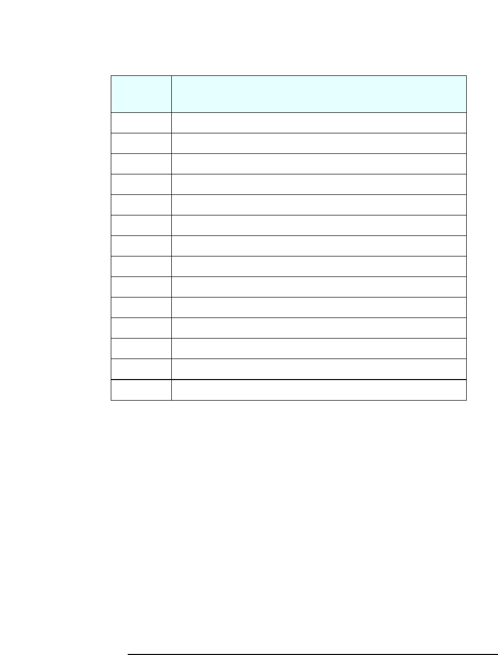
NotethatforMemory(code3),VideoCard(code4),andPnP/PCI(code5)
errors, e-DiagTools preboot diagnostic will only detect them after a 15-second
timeout.
If you miss the beep code, turn off the PC. Then press the on/off power
button for five seconds or more, then listen for the signal again.
The e-DiagTools preboot diagnostic, as well as emitting a beep sequence, also
encodes troubleshooting information (such as the PC models, serial number,
and failing component) into a coded audio signal. During a support call, this
coded signal can then be decoded by the HP Service Provider to provide
immediate and effective assistance.
Number
of Beeps
Meaning
0SystemOK
1 Processor absent, not correctly connected or ZIP socket not closed
2 Power supply is in protected mode
3 No memory, bad memory modules, incompatible memory module
4 Graphics card problem
5 PnP/PCI initialization problem
6 Corrupted BIOS. You need to activate crisis recovery procedure.
7 Defective system board

58
4 BIOS Overview
HP e-DiagTools Preboot Diagnostic (Beep Codes)

5
Drivers and Software
This chapter describes the drivers and software preloaded with
HP Vectra VL400 PCs.

60
5 Drivers and Software
Drivers
Drivers
You can download up-to-date versions of drivers required for VL400 PCs from
the “Software and Drivers” section of HP’s Support web site at
www.hp.com/go/vectrasupport.
Software
VL400 models come preloaded with the following software. You can download
the most up-to-date versions from the “Software and Drivers” section of HP’s
Support web site at www.hp.com/go/vectrasupport.
Operating Systems Either Windows 2000 (with Windows NT4 SP6 as alternative on CD-ROM), or
Windows95(withWindows98SEasalternativeonCD-ROM).
Software • e-DiagTools 3.0
•NTLock
•CD-R/WorDVDsoftware
• Soft Power Down (Windows NT4)
• TopTools
•SafeOff
• Anti-Virus software (on CD-ROM).
e-DiagTools HP e-DiagTools, the hardware diagnostics utility can help you diagnose
hardware-related problems on your HP PC. For more information about this
utility, refer to the e-Diagtools User's Guide.Thee-DiagtoolsUser'sGuide
is available on the HP Information CD-ROM for the VL400, or on HP’s
support web site (www.hp.com/go/vectrasupport).
e-DiagTools is installed on the Utility Partition on the PC’s hard disk drive, is
provided on one of the CD-ROMS that came with the PC (HP Image Library
and Diagnostics System CD-ROM), and is available on the HP e-DiagTools
CD (you can order this CD-ROM from HP’s Support web site).

61
5 Drivers and Software
BIOS Updates
BIOS Updates
The system BIOS is identified by the version number IP.xx.xx.Thelatest
BIOS version for your PC and instructions for updating the BIOS can be
downloaded from the HP support Web site at:
www.hp.com/go/vectrasupport.

62
5 Drivers and Software
BIOS Updates

The Technical Reference Manual contains the following
documents available on the HP Information CD-ROM or
downloadable from the Web in PDF format:
•Introduction & HP Vectra Product Line Overview
Describes how to use the Technical Reference Manual and provides
a brief overview of the Vectra product line.
•Product Description
The document you are reading. A separate document exists for
VEi7, VEi8, VL400, VL600, VLi8, VLi8SF, and e-Vectra PCs,
providing detailed BIOS information and summary information on
the hardware components in the PC.
•HP Vectra Technology
A detailed look at the hardware components in all the PCs in the
product line. Includes information on processors, chipsets, graphics
controllers, network cards, connectors and sockets.
