HUAC F15C-CP-M Cellular signal booster User Manual
SHENZHEN HUAPTEC CO., LTD Cellular signal booster
UserManual.wiki
>
HUAC
>
F15C CP M User Manual
User manual
Navigation menu
Upload a User Manual
Namespaces
Wiki Guide
HTML
PDF
Info
Views
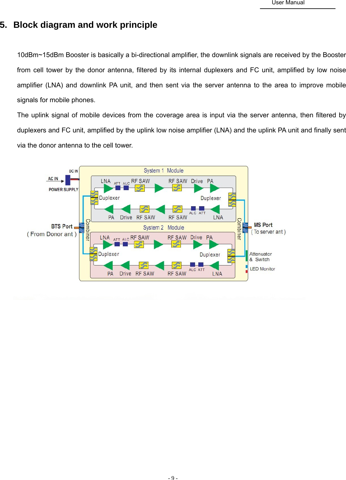
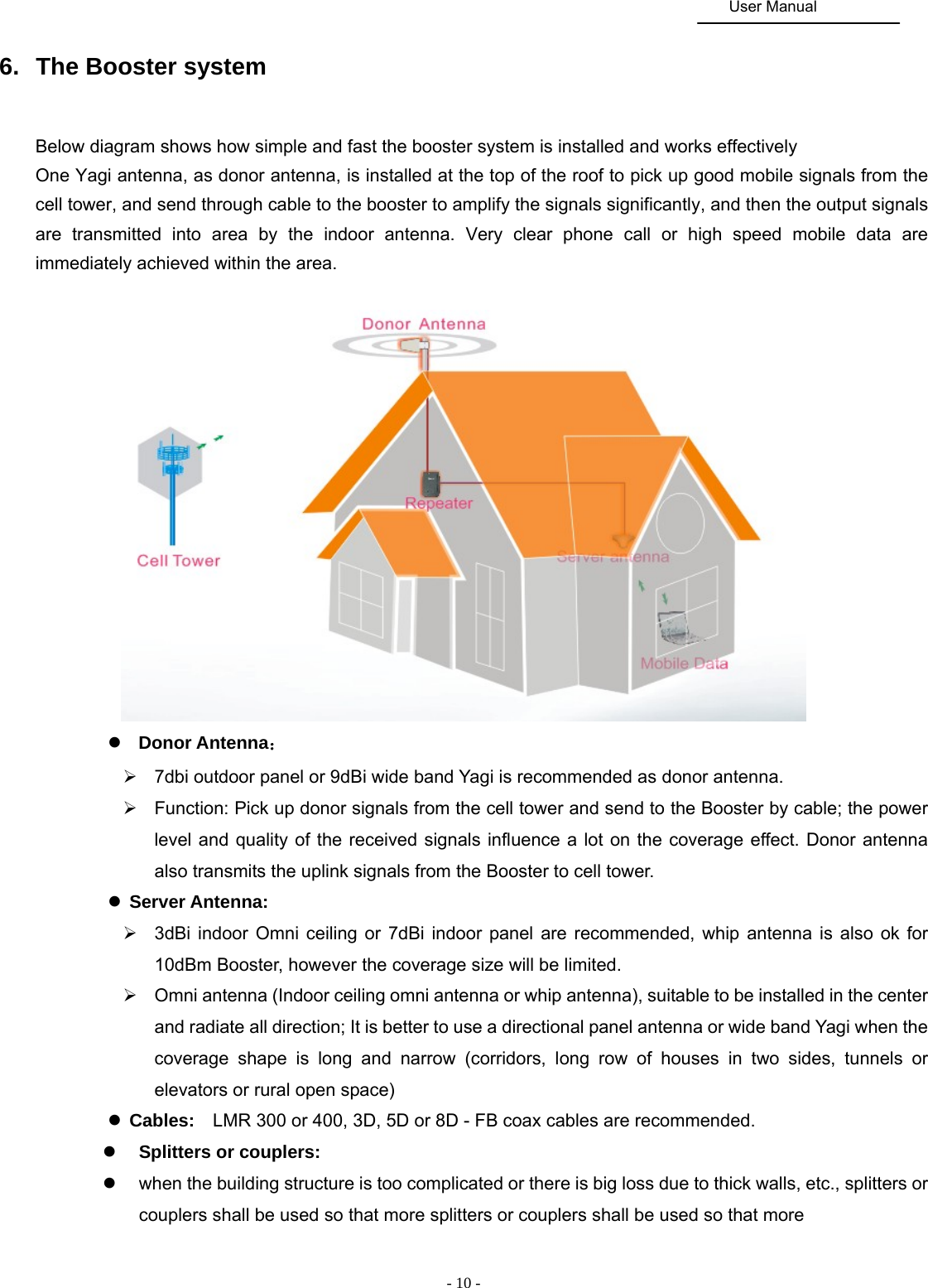
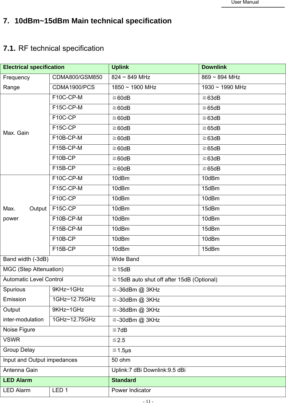
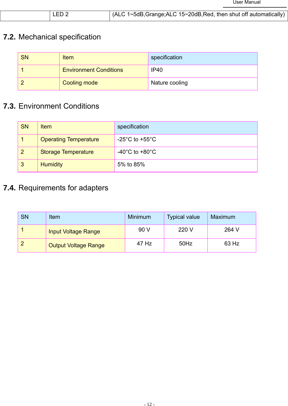
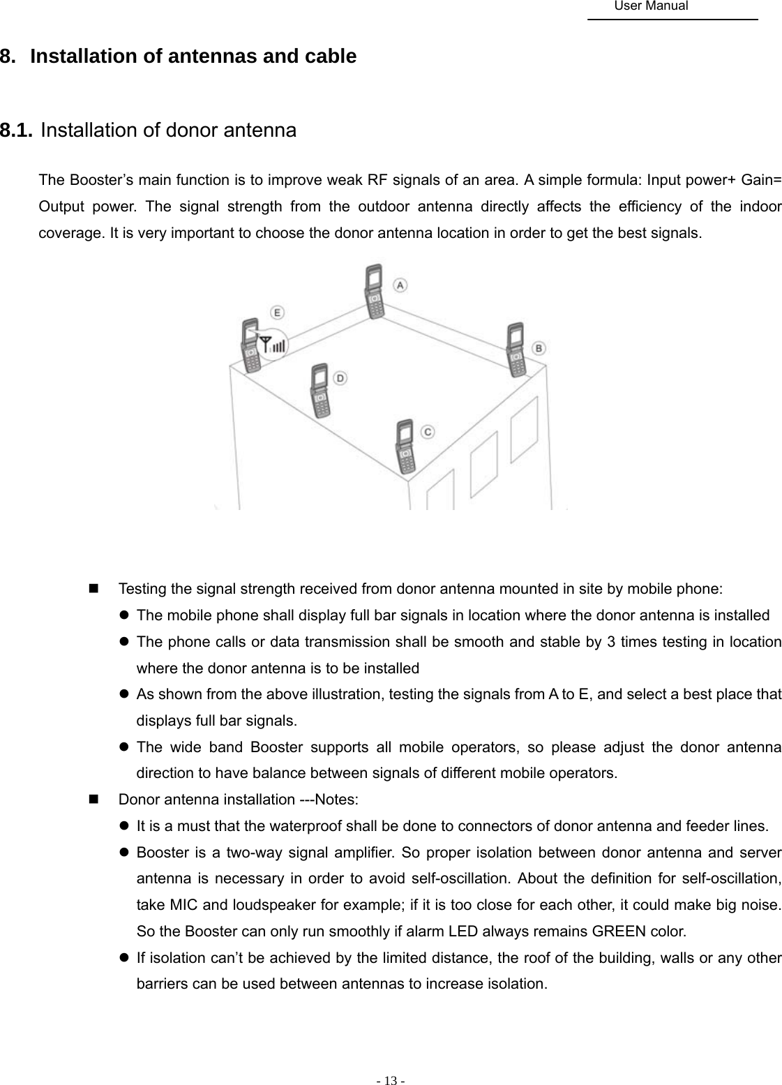
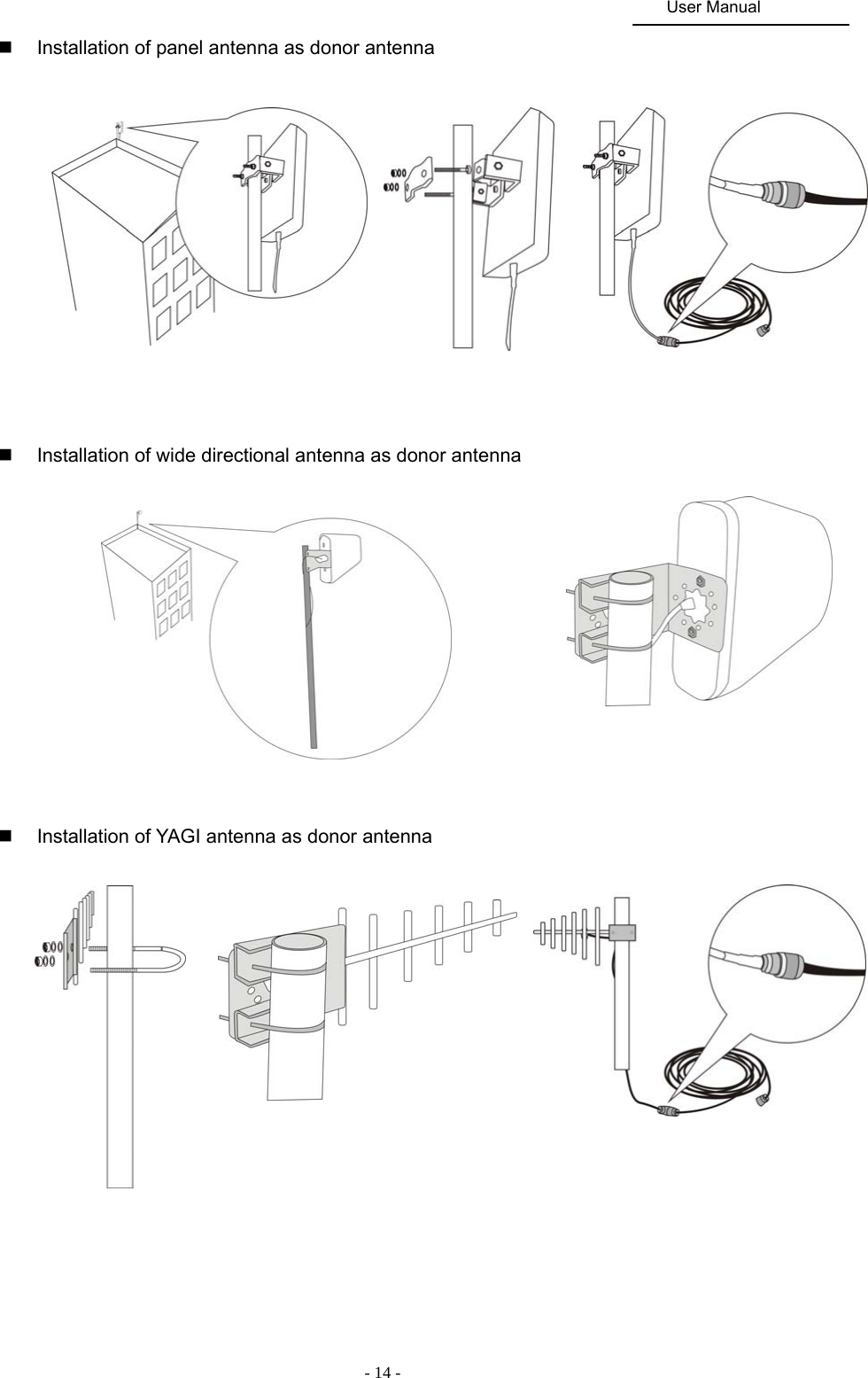
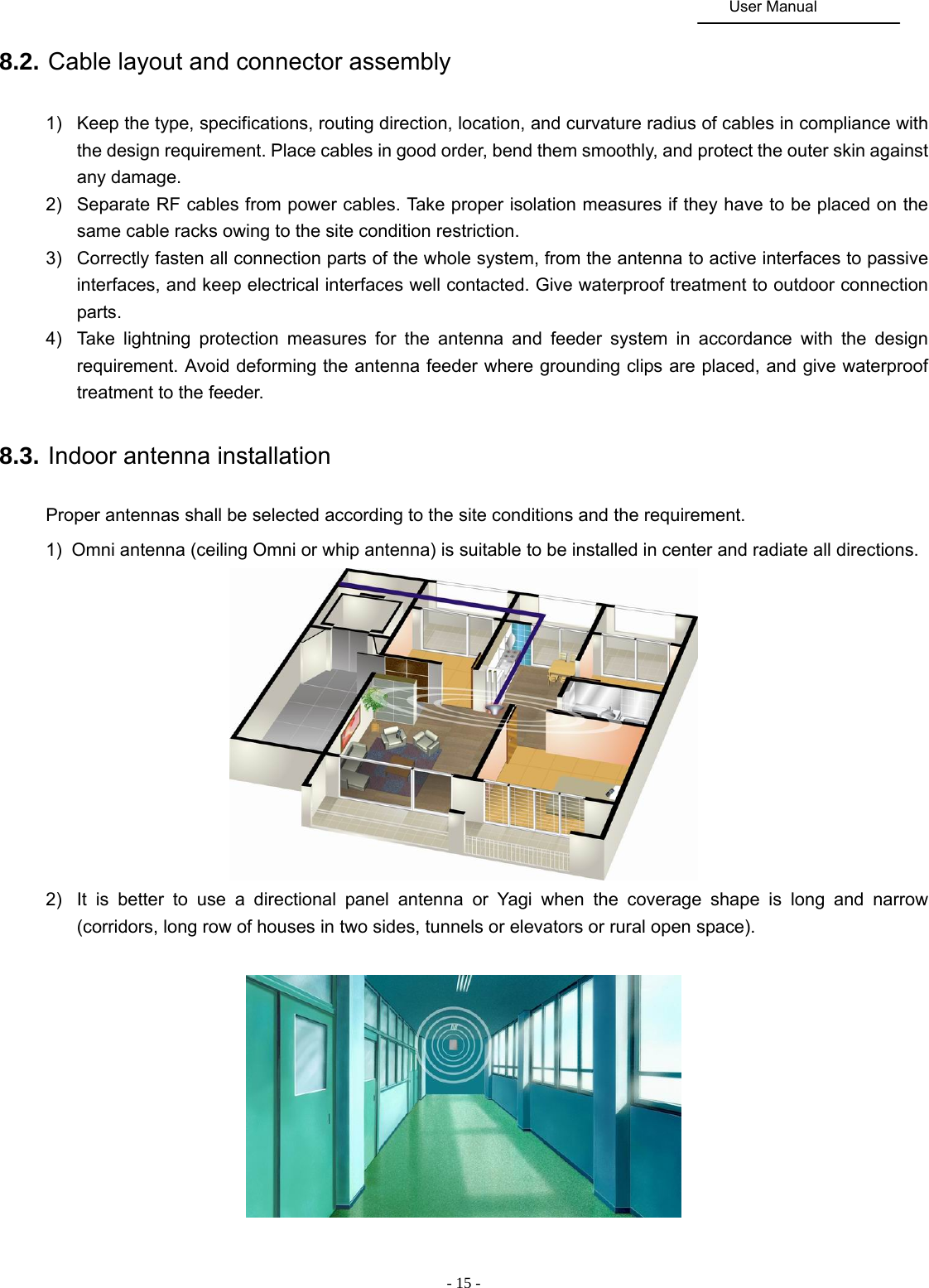
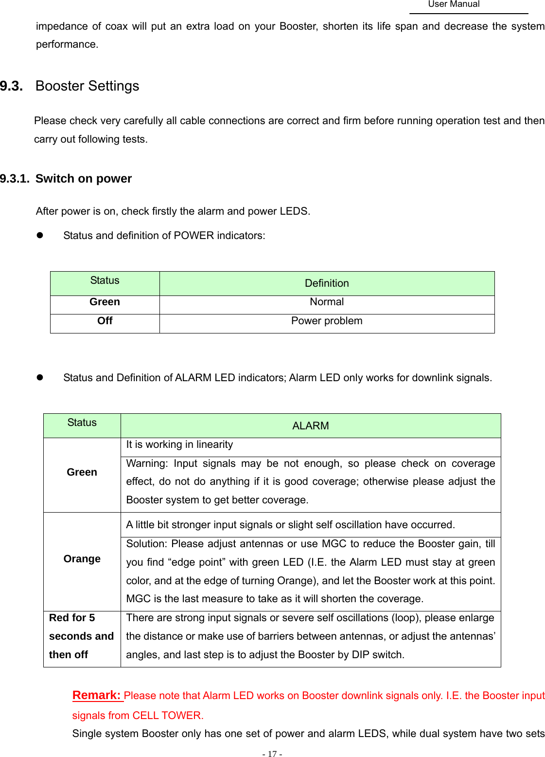
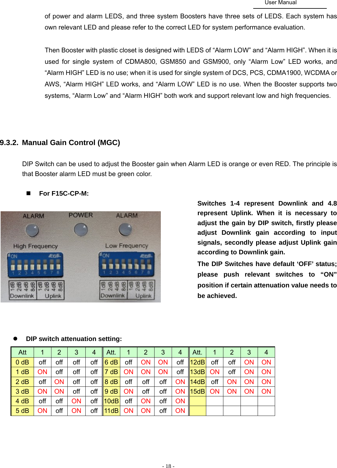
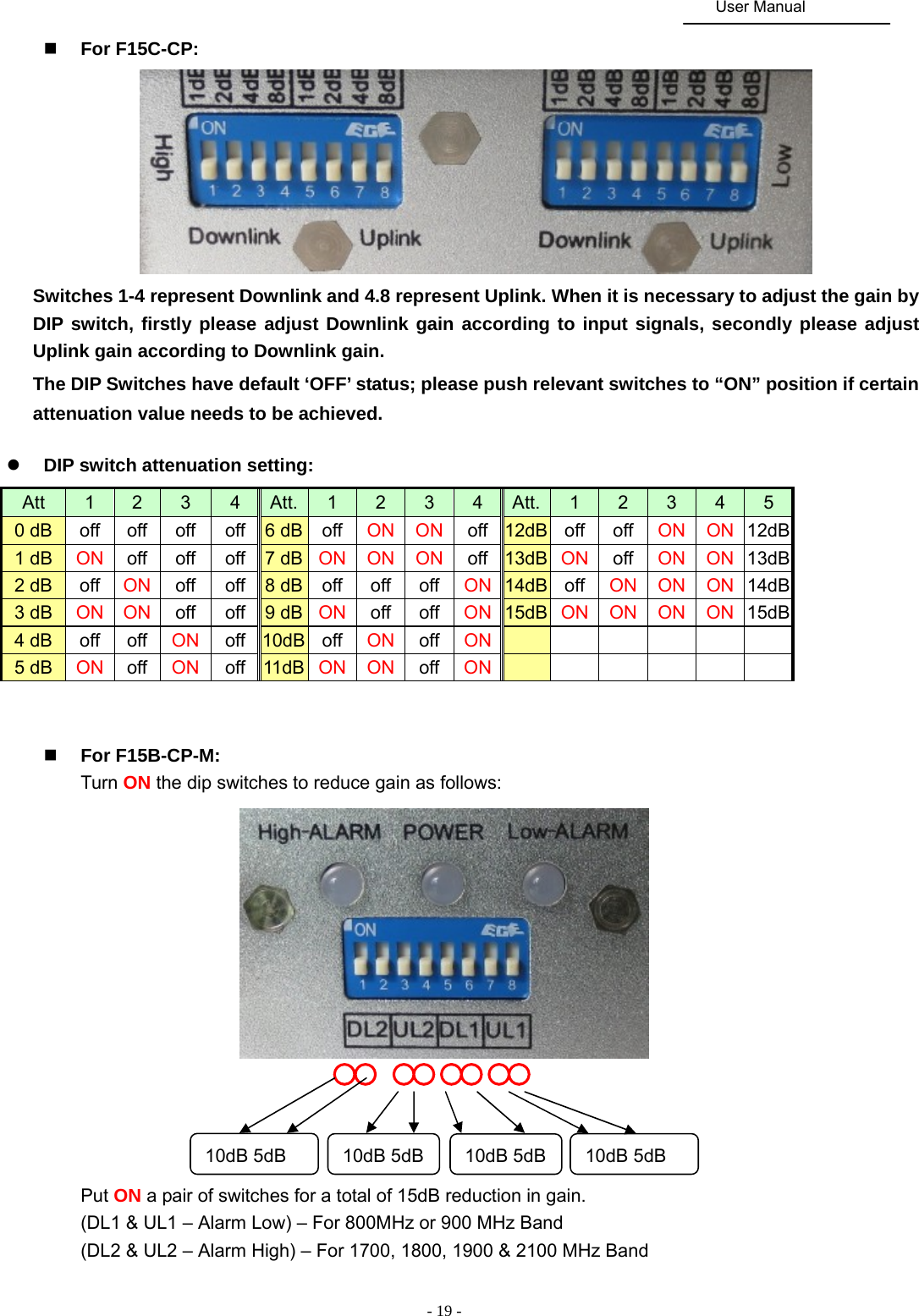
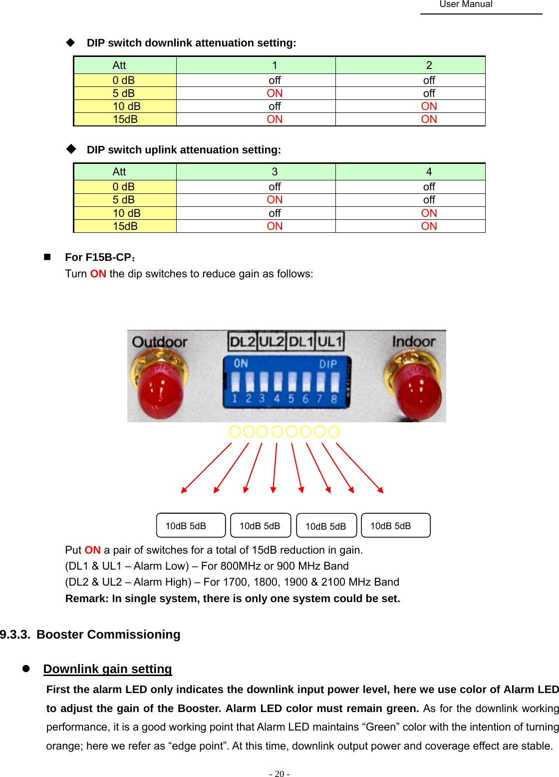
User Manual
Discussion / Help
Navigation