HUAC F15C-CP-M Cellular signal booster User Manual
SHENZHEN HUAPTEC CO., LTD Cellular signal booster
HUAC >
User manual

Cellular signal booster
User’s Manual

User Manual
- 2 -
PREFACE ............................................................................................................................................................................... 3
1.SAFETY WARNINGS ......................................................................................................................................................... 3
2.WHY BOOSTER ................................................................................................................................................................. 4
2.1.REASON......................................................................................................................................................................... 4
2.2.SOLUTION ...................................................................................................................................................................... 4
3.INTRODUCTION ................................................................................................................................................................. 6
4.SYSTEM CHARACTERISTICS .......................................................................................................................................... 7
4.1.FEATURES ...................................................................................................................................................................... 7
4.2.APPEARANCE OF THE BOOSTERS .................................................................................................................................... 7
5.BLOCK DIAGRAM AND WORK PRINCIPLE .................................................................................................................... 9
6.THE BOOSTER SYSTEM ................................................................................................................................................ 10
7.10DBM~15DBM MAIN TECHNICAL SPECIFICATION ................................................................................................... 11
7.1.RF TECHNICAL SPECIFICATION ....................................................................................................................................... 11
7.2.MECHANICAL SPECIFICATION ......................................................................................................................................... 12
7.3.ENVIRONMENT CONDITIONS .......................................................................................................................................... 12
7.4.REQUIREMENTS FOR ADAPTERS .................................................................................................................................... 12
8.INSTALLATION OF ANTENNAS AND CABLE ............................................................................................................... 13
8.1.INSTALLATION OF DONOR ANTENNA ................................................................................................................................ 13
8.2.CABLE LAYOUT AND CONNECTOR ASSEMBLY ................................................................................................................... 15
8.3.INDOOR ANTENNA INSTALLATION .................................................................................................................................... 15
9.BOOSTER INSTALLATION ............................................................................................................................................. 16
9.1.INSTALLATION REQUIREMENT ......................................................................................................................................... 16
9.1.1.Installation Location Requirement .................................................................................................................. 16
9.1.2.Power requirement ......................................................................................................................................... 16
9.2.INSTALLATION STEPS .................................................................................................................................................... 16
9.2.1.Installation schemes ....................................................................................................................................... 16
9.2.2.Booster’s ports description ............................................................................................................................. 16
9.2.3.Accessories selection ..................................................................................................................................... 16
9.3.BOOSTER SETTINGS ..................................................................................................................................................... 17
9.3.1.Switch on power ............................................................................................................................................. 17
9.3.2.Manual Gain Control (MGC) .......................................................................................................................... 18
9.3.3.Booster Commissioning ................................................................................................................................. 20
9.4.SYSTEM TEST .............................................................................................................................................................. 22
9.4.1.Check whether the coverage is good ............................................................................................................. 22
9.4.2.Booster can not communicate in Power-ON status ....................................................................................... 23
User Manual
- 3 -
Preface
This user’s manual describes the installation, commissioning and maintenance of wide band
consumer boosters. Please do read user manual carefully before installing and maintaining
the Boosters. The information in this manual is subject to change without prior notice.
1. Safety Warnings
Users must follow the below principles:
z Booster should follow system requirement of communication equipment, assure good
grounding and lightning protection.
z The power supply voltage of Booster should meet the standards of security requirement; any
operation shall be carried out only after cutting off power in advance. Only the professional is
authorized for the operation.
z Do not dismantle machine, maintain or displace accessories by yourself, because in
this way, the equipment may be damaged and you may even get an electric shock.
z Do not open the Booster, touch the module of Booster, or open the cover of module to touch
the electronic component. The components will be damaged due to electrostatic.
z Please keep away from heating-equipment, because the Booster will dissipate heat during
working. And do not cover booster with anything that influences heat-dissipation.

User Manual
- 4 -
2. Why Booster
2.1. Reason
1) Blind or weak signal areas are formed if the buildings are too far away from CELL TOWER, or the buildings
themselves shield or absorb signals.
2) There are too many complicated signals in the higher part of the buildings, therefore ping-pong switching
effect has been formed and the signals fluctuate a lot, there are annoying noises during phone calls and
call drops accordingly.
3) Elevators and basements are well-known for blind areas.
4) Downtown areas of the cities, which congested with many high-rise buildings, are usually the weak or blind
areas.
5) The remote villages, mountains, hills, valleys, etc. are mostly populated areas with quite few mobile
users, so the main target is to send coverage to these areas, and it will not be worthy installing a CELL
TOWER, therefore a booster is a quite good option.
2.2. Solution
Can we not use mobile phones? The answer is definitely NO. But it might be much more miserable that the
communication can’t be achieved due to no signal or weak signals though there is a mobile phone.
Will your customers stay comfortable when there is no smooth communication in your shops or restaurants?
Will that be frustrating if your clients couldn’t call you through due to weak signals in offices?
Will your life be influenced if your mobile is always “out of service” at home when your friends call you?
Then how to solve the problems?
Best Solution:
Plug & play: Purchase a set of Booster solution from us and install it, and immediately you would be
able to enjoy the full bar and high quality signals!
User Manual
- 5 -
Question: Will booster increase the RF radiation?
A: No, it will decrease instead.
As it can be searched easily through internet, the tower would “order” the mobile phone to increase its output
power, in order to ensure successful connection when the mobile signal bar is few, there will be stronger mobile
output power level when the mobile signal bar is less and the strongest one can reach 2W (GSM); moreover,
the mobile phone is usually as near as less than 5cm to human body when people are in phone calls. Not only
it influences the human bodies badly, but also run out of the battery power much more quickly; usually the
mobile phone gets hot in such status.
For example, the maximum power level of booster is 1.0W, and it decreases to be maximum 0.05W when
reaching server antenna. And since the server antenna is installed over the ceiling or onto the wall, there is
usually more than 3 meter away from the human body, 3meter away means at least 40dB propagation loss, or
10000 times less, 0.000005W, and therefore it is too weak to influence human bodies though it is still a very
good signal for mobile phones.
And when a booster is installed, it improves the mobile signals in the coverage, and the successful phone call
can be connected easily with a much less power level of the mobile phone, thus it will reduce the RF radiation
of the mobile phone tremendously.
User Manual
- 6 -
3. Introduction
Our 10dBm~15dBm Booster is the perfect solution for providing a wireless improvement in the cellular reception
of a home, office, restaurant, VIP Room, apartment, building or shopping mall, in the quickest time possibly. One
Booster covers 300 to 3000 square meters.
This Booster has Manual Gain Control (MGC) feature that enables engineers to reduce the gain of the Booster
manually if oscillation is detected or too strong input power level during installation, which will help to get the
best coverage effect without any interference back to mobile network.
And in order to maintain safe and specific output signal levels, this Booster has built-in signal oscillation
detection circuit to adjust the gain automatically so as to avoid interference to the cellular network, also it gets
color changing LED’s indicating its environmental status: the Alarm LED’s located on the front of the unit will
change color from green to orange or red, (depending on the input power level) if the system detects signal
oscillation in either band or, if the input signal is beyond a safe limit.
Our Boosters also feature a Network Safe / MUTE feature that automatically shuts off the Booster to protect the
cellular network if no adjustments are made to eliminate alarm readings on the Booster’s LED’s. You will want to
make sure the LED’s remain green at all times for optimum system performance. (This function is not available
for some specific models for which we will specify when you purchase)
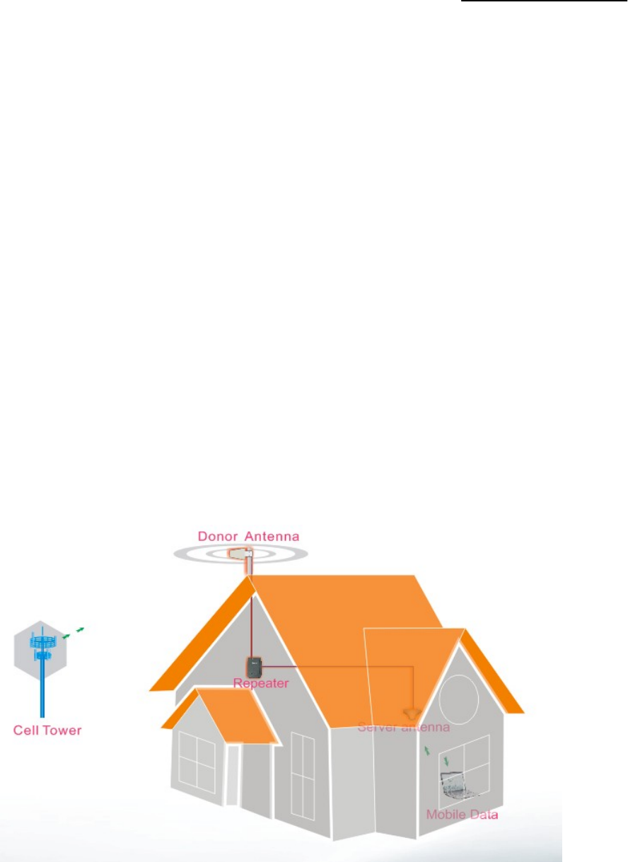
Below diagram shows how simple and fast 10dBm~15dBm Booster system is installed and works effectively
One Yagi antenna, as donor antenna, is installed at the top of the roof to pick up good mobile signals from
outside, and send through 5D-FB cable to 10dBm~15dBm Booster to amplify the signals significantly, then the
output signals are divided into two signals by 2way splitter, sent to two indoor omni antennas and finally
transmitted into area. Very clear phone call or high speed mobile data are immediately achieved within the area.
User Manual
- 7 -
4. System Characteristics
4.1. Features
z Streamline shape.
z Wide band Booster to support signals of all operators.
z High-integration (One board to contain low-noise amplifier, frequency selection module, power amplifier
module, both uplink and downlink one for all).
z Manual gain control provides a variety of applications.
z Auto automatic gain control to stabilize the coverage and minimize the noises.
z Auto shut off function as final step to avoid severe interference with mobile network (not available for some
models).
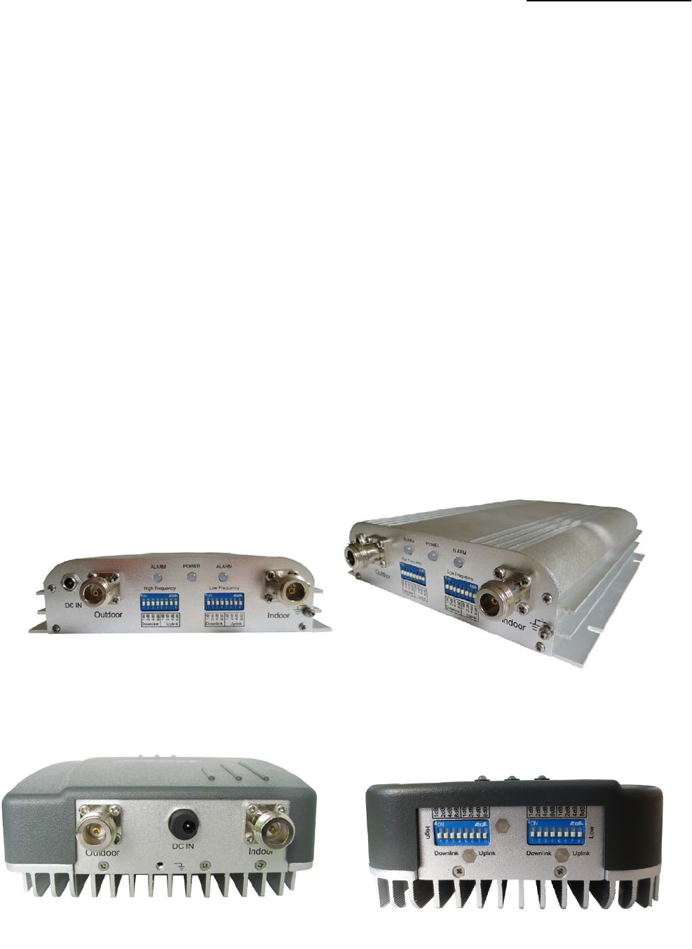
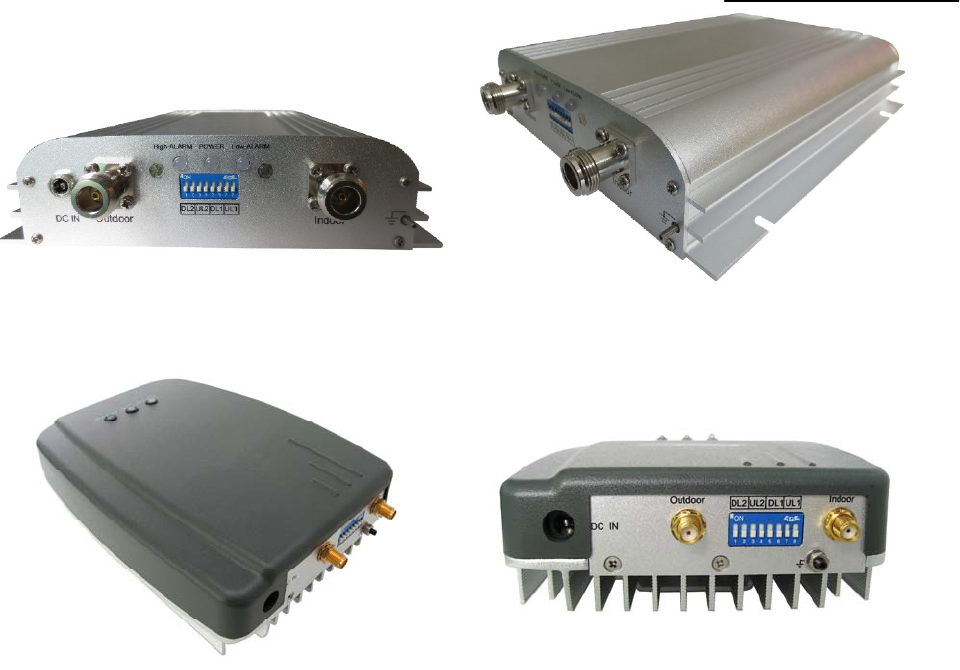
4.2. Appearance of the Boosters
Note: Below figure shows some typical products’ photos; while some others can be
obtained by querying.
F10~F15C-CP-M dual system Booster
F10C~F15C-CP dual system Booster
User Manual
- 8 -
F10B~F15B-CP-M dual system Booster
F10B~F15B-CP dual system Booster
User Manual
- 9 -
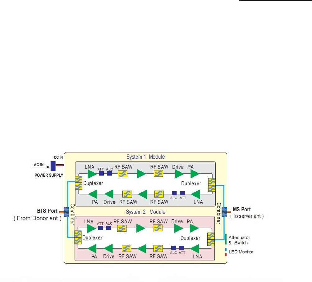
5. Block diagram and work principle
10dBm~15dBm Booster is basically a bi-directional amplifier, the downlink signals are received by the Booster
from cell tower by the donor antenna, filtered by its internal duplexers and FC unit, amplified by low noise
amplifier (LNA) and downlink PA unit, and then sent via the server antenna to the area to improve mobile
signals for mobile phones.
The uplink signal of mobile devices from the coverage area is input via the server antenna, then filtered by
duplexers and FC unit, amplified by the uplink low noise amplifier (LNA) and the uplink PA unit and finally sent
via the donor antenna to the cell tower.
User Manual
- 10 -
6. The Booster system
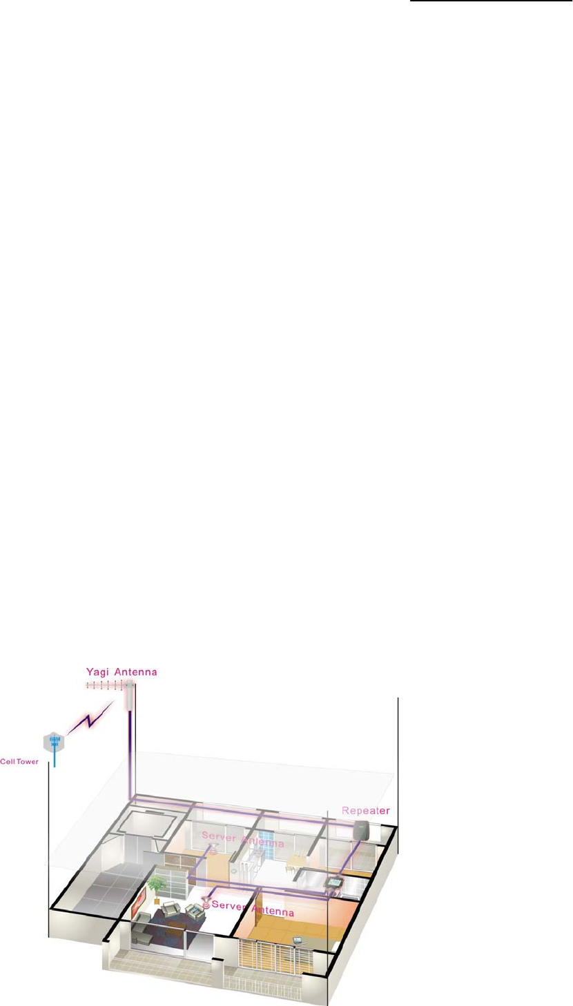
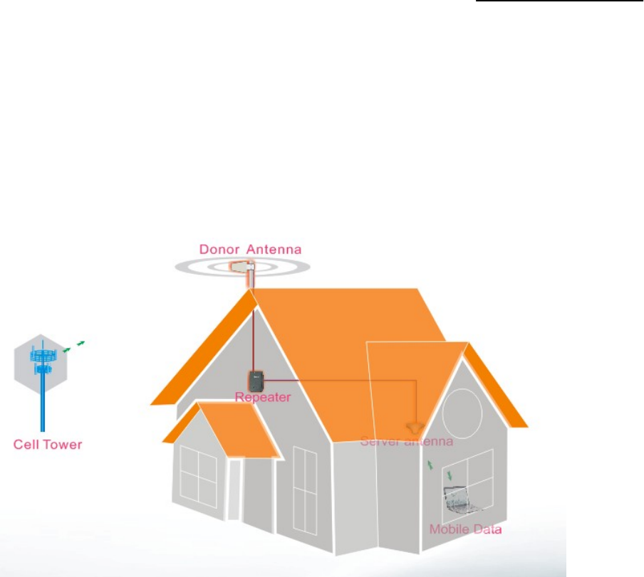
Below diagram shows how simple and fast the booster system is installed and works effectively
One Yagi antenna, as donor antenna, is installed at the top of the roof to pick up good mobile signals from the
cell tower, and send through cable to the booster to amplify the signals significantly, and then the output signals
are transmitted into area by the indoor antenna. Very clear phone call or high speed mobile data are
immediately achieved within the area.
z Donor Antenna:
¾ 7dbi outdoor panel or 9dBi wide band Yagi is recommended as donor antenna.
¾ Function: Pick up donor signals from the cell tower and send to the Booster by cable; the power
level and quality of the received signals influence a lot on the coverage effect. Donor antenna
also transmits the uplink signals from the Booster to cell tower.
z Server Antenna:
¾ 3dBi indoor Omni ceiling or 7dBi indoor panel are recommended, whip antenna is also ok for
10dBm Booster, however the coverage size will be limited.
¾ Omni antenna (Indoor ceiling omni antenna or whip antenna), suitable to be installed in the center
and radiate all direction; It is better to use a directional panel antenna or wide band Yagi when the
coverage shape is long and narrow (corridors, long row of houses in two sides, tunnels or
elevators or rural open space)
z Cables: LMR 300 or 400, 3D, 5D or 8D - FB coax cables are recommended.
z Splitters or couplers:
z when the building structure is too complicated or there is big loss due to thick walls, etc., splitters or
couplers shall be used so that more splitters or couplers shall be used so that more
User Manual
- 11 -
7. 10dBm~15dBm Main technical specification
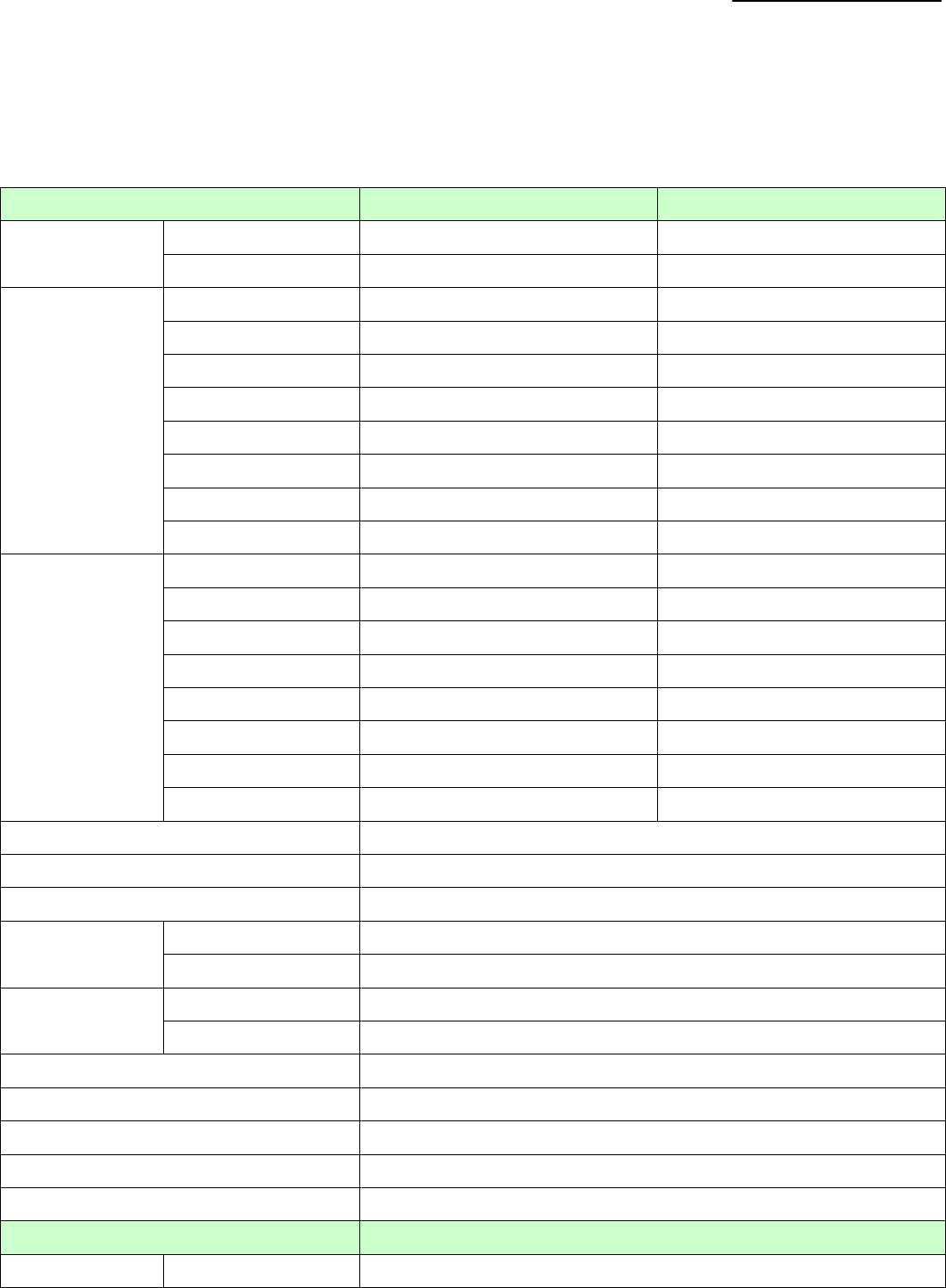
7.1. RF technical specification
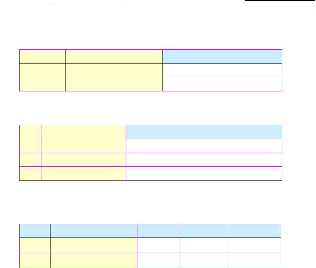
Electrical specification Uplink Downlink
Frequency
Range
CDMA800/GSM850 824 ~ 849 MHz 869 ~ 894 MHz
CDMA1900/PCS 1850 ~ 1900 MHz 1930 ~ 1990 MHz
Max. Gain
F10C-CP-M ≧60dB ≧63dB
F15C-CP-M ≧60dB ≧65dB
F10C-CP ≧60dB ≧63dB
F15C-CP ≧60dB ≧65dB
F10B-CP-M ≧60dB ≧63dB
F15B-CP-M ≧60dB ≧65dB
F10B-CP ≧60dB ≧63dB
F15B-CP ≧60dB ≧65dB
Max. Output
power
F10C-CP-M 10dBm 10dBm
F15C-CP-M 10dBm 15dBm
F10C-CP 10dBm 10dBm
F15C-CP 10dBm 15dBm
F10B-CP-M 10dBm 10dBm
F15B-CP-M 10dBm 15dBm
F10B-CP 10dBm 10dBm
F15B-CP 10dBm 15dBm
Band width (-3dB) Wide Band
MGC (Step Attenuation) ≧15dB
Automatic Level Control ≧15dB auto shut off after 15dB (Optional)
Spurious
Emission
9KHz~1GHz ≦-36dBm @ 3KHz
1GHz~12.75GHz ≦-30dBm @ 3KHz
Output
inter-modulation
9KHz~1GHz ≦-36dBm @ 3KHz
1GHz~12.75GHz ≦-30dBm @ 3KHz
Noise Figure ≦7dB
VSWR ≦2.5
Group Delay ≦1.5μs
Input and Output impedances 50 ohm
Antenna Gain Uplink:7 dBi Downlink:9.5 dBi
LED Alarm Standard
LED Alarm LED 1 Power Indicator
User Manual
- 12 -
LED 2 (ALC 1~5dB,Grange;ALC 15~20dB,Red, then shut off automatically)
7.2. Mechanical specification
SN Item specification
1 Environment Conditions IP40
2 Cooling mode Nature cooling
7.3. Environment Conditions
SN Item specification
1 Operating Temperature -25°C to +55°C
2 Storage Temperature -40°C to +80°C
3 Humidity 5% to 85%
7.4. Requirements for adapters
SN Item Minimum Typical value Maximum
1 Input Voltage Range 90 V 220 V 264 V
2 Output Voltage Range 47 Hz 50Hz 63 Hz
User Manual
- 13 -
8. Installation of antennas and cable
8.1. Installation of donor antenna
The Booster’s main function is to improve weak RF signals of an area. A simple formula: Input power+ Gain=
Output power. The signal strength from the outdoor antenna directly affects the efficiency of the indoor
coverage. It is very important to choose the donor antenna location in order to get the best signals.
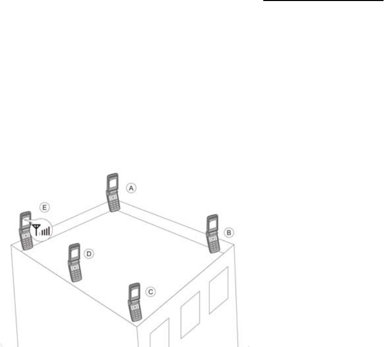
Testing the signal strength received from donor antenna mounted in site by mobile phone:
z The mobile phone shall display full bar signals in location where the donor antenna is installed
z The phone calls or data transmission shall be smooth and stable by 3 times testing in location
where the donor antenna is to be installed
z As shown from the above illustration, testing the signals from A to E, and select a best place that
displays full bar signals.
z The wide band Booster supports all mobile operators, so please adjust the donor antenna
direction to have balance between signals of different mobile operators.
Donor antenna installation ---Notes:
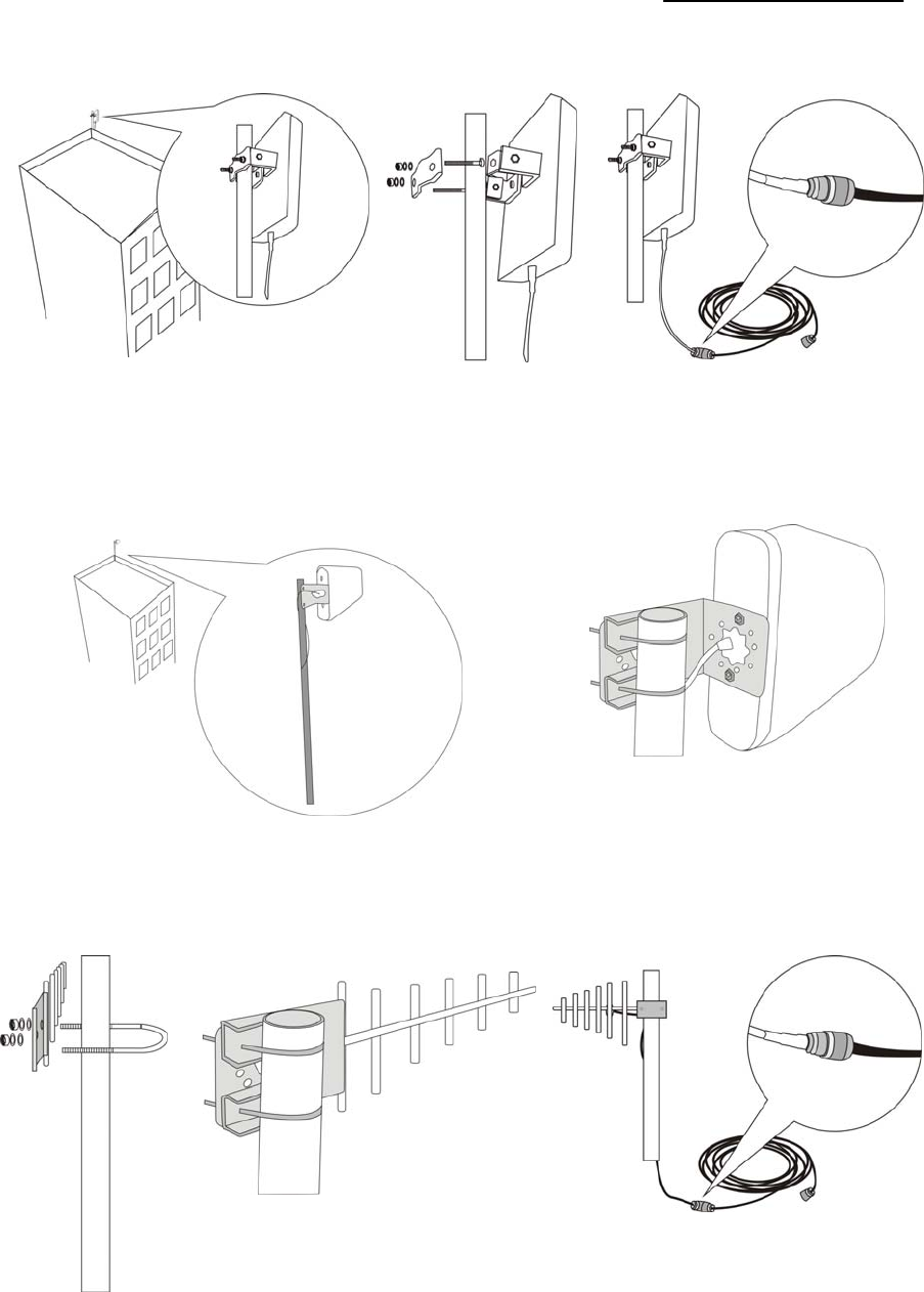
z It is a must that the waterproof shall be done to connectors of donor antenna and feeder lines.
z Booster is a two-way signal amplifier. So proper isolation between donor antenna and server
antenna is necessary in order to avoid self-oscillation. About the definition for self-oscillation,
take MIC and loudspeaker for example; if it is too close for each other, it could make big noise.
So the Booster can only run smoothly if alarm LED always remains GREEN color.
z If isolation can’t be achieved by the limited distance, the roof of the building, walls or any other
barriers can be used between antennas to increase isolation.
User Manual
- 14 -
Installation of panel antenna as donor antenna
Installation of wide directional antenna as donor antenna
Installation of YAGI antenna as donor antenna
User Manual
- 15 -
8.2. Cable layout and connector assembly
1) Keep the type, specifications, routing direction, location, and curvature radius of cables in compliance with
the design requirement. Place cables in good order, bend them smoothly, and protect the outer skin against
any damage.
2) Separate RF cables from power cables. Take proper isolation measures if they have to be placed on the
same cable racks owing to the site condition restriction.
3) Correctly fasten all connection parts of the whole system, from the antenna to active interfaces to passive
interfaces, and keep electrical interfaces well contacted. Give waterproof treatment to outdoor connection
parts.
4) Take lightning protection measures for the antenna and feeder system in accordance with the design
requirement. Avoid deforming the antenna feeder where grounding clips are placed, and give waterproof
treatment to the feeder.
8.3. Indoor antenna installation
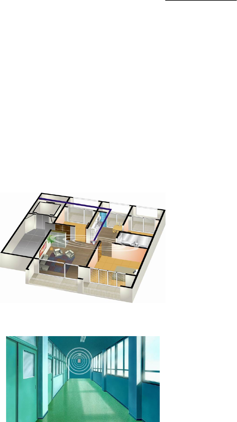
Proper antennas shall be selected according to the site conditions and the requirement.
1) Omni antenna (ceiling Omni or whip antenna) is suitable to be installed in center and radiate all directions.
2) It is better to use a directional panel antenna or Yagi when the coverage shape is long and narrow
(corridors, long row of houses in two sides, tunnels or elevators or rural open space).

User Manual
- 16 -
9. Booster Installation
9.1. Installation requirement
9.1.1. Installation Location Requirement
1) The Booster shall be installed indoor in a cool, dry and ventilated room without erosive gas or smoke, or a
cool and ventilated wall to ensure excellent heat dissipation
2) Installation height should be easy for RF cable wiring, heat dissipation, security and maintenance.
3) Have a set of independent and stable power supply.
9.1.2. Power requirement
Generally it is AC power supply, and the requirement of AC is 100~264VAC / 50±5Hz
9.2. Installation Steps
9.2.1. Installation schemes
The booster shall be installed in indoor areas only
1) Connect the power supply and the cables properly to the Booster ports
2) Check again to make sure the Booster is installed firmly and Booster alarm LED must stay green.
9.2.2. Booster’s ports description
1) Outdoor port: connected with the donor antenna by cable
2) Indoor port: connected with server antenna directly or by cable
3) DC IN: connected with power supply.
9.2.3. Accessories selection
Please pay attention to the two points of “frequency” and “impedance” during the selection of the accessories.
All accessories shall support the Booster’s frequencies from feeder line, antenna and splitter to combiners
etc. For example, the Booster’s frequency is GSM900, so all the accessories must support the GSM900
frequency. And the Booster’s impedance is 50ohm, so the accessories shall all be 50ohm. To use any other
User Manual
- 17 -
impedance of coax will put an extra load on your Booster, shorten its life span and decrease the system
performance.
9.3. Booster Settings
Please check very carefully all cable connections are correct and firm before running operation test and then
carry out following tests.
9.3.1. Switch on power
After power is on, check firstly the alarm and power LEDS.
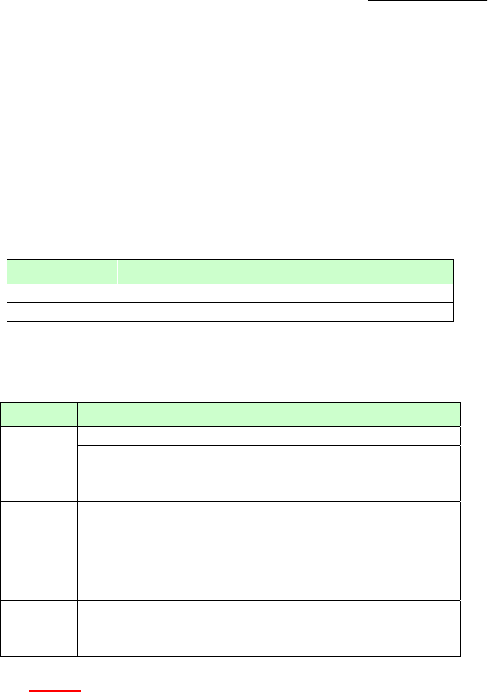
z Status and definition of POWER indicators:
z Status and Definition of ALARM LED indicators; Alarm LED only works for downlink signals.
Status ALARM
Green
It is working in linearity
Warning: Input signals may be not enough, so please check on coverage
effect, do not do anything if it is good coverage; otherwise please adjust the
Booster system to get better coverage.
Orange
A little bit stronger input signals or slight self oscillation have occurred.
Solution: Please adjust antennas or use MGC to reduce the Booster gain, till
you find “edge point” with green LED (I.E. the Alarm LED must stay at green
color, and at the edge of turning Orange), and let the Booster work at this point.
MGC is the last measure to take as it will shorten the coverage.
Red for 5
seconds and
then off
There are strong input signals or severe self oscillations (loop), please enlarge
the distance or make use of barriers between antennas, or adjust the antennas’
angles, and last step is to adjust the Booster by DIP switch.
Remark: Please note that Alarm LED works on Booster downlink signals only. I.E. the Booster input
signals from CELL TOWER.
Single system Booster only has one set of power and alarm LEDS, while dual system have two sets
Status Definition
Green Normal
Off Power problem
User Manual
- 18 -
of power and alarm LEDS, and three system Boosters have three sets of LEDS. Each system has
own relevant LED and please refer to the correct LED for system performance evaluation.
Then Booster with plastic closet is designed with LEDS of “Alarm LOW” and “Alarm HIGH”. When it is
used for single system of CDMA800, GSM850 and GSM900, only “Alarm Low” LED works, and
“Alarm HIGH” LED is no use; when it is used for single system of DCS, PCS, CDMA1900, WCDMA or
AWS, “Alarm HIGH” LED works, and “Alarm LOW” LED is no use. When the Booster supports two
systems, “Alarm Low” and “Alarm HIGH” both work and support relevant low and high frequencies.
9.3.2. Manual Gain Control (MGC)
DIP Switch can be used to adjust the Booster gain when Alarm LED is orange or even RED. The principle is
that Booster alarm LED must be green color.
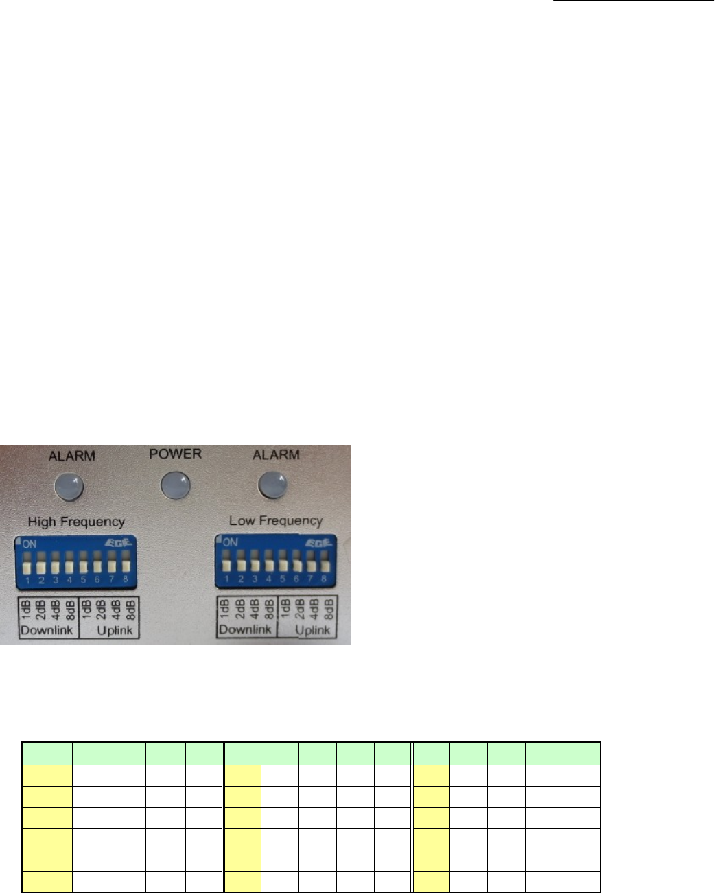
For F15C-CP-M:
Switches 1-4 represent Downlink and 4.8
represent Uplink. When it is necessary to
adjust the gain by DIP switch, firstly please
adjust Downlink gain according to input
signals, secondly please adjust Uplink gain
according to Downlink gain.
The DIP Switches have default ‘OFF’ status;
please push relevant switches to “ON”
position if certain attenuation value needs to
be achieved.
z DIP switch attenuation setting:
Att 1 2 3 4 Att. 1 2 3 4 Att. 1 2 3 4
0 dB off off off off 6 dB off ON ON off 12dB off off ON ON
1 dB ON off off off 7 dB ON ON ON off 13dB ON off ON ON
2 dB off ON off off 8 dB off off off ON 14dB off ON ON ON
3 dB ON ON off off 9 dB ON off off ON 15dB ON ON ON ON
4 dB off off ON off 10dB off ON off ON
5 dB ON off ON off 11dB ON ON off ON
User Manual
- 19 -
For F15C-CP:
Switches 1-4 represent Downlink and 4.8 represent Uplink. When it is necessary to adjust the gain by
DIP switch, firstly please adjust Downlink gain according to input signals, secondly please adjust
Uplink gain according to Downlink gain.
The DIP Switches have default ‘OFF’ status; please push relevant switches to “ON” position if certain
attenuation value needs to be achieved.
z DIP switch attenuation setting:
Att 1 2 3 4 Att. 1 2 3 4 Att. 1 2 3 4 5
0 dB off off off off 6 dB off ON ON off 12dB off off ON ON 12dB
1 dB ON off off off 7 dB ON ON ON off 13dB ON off ON ON 13dB
2 dB off ON off off 8 dB off off off ON 14dB off ON ON ON 14dB
3 dB ON ON off off 9 dB ON off off ON 15dB ON ON ON ON 15dB
4 dB off off ON off 10dB off ON off ON
5 dB ON off ON off 11dB ON ON off ON
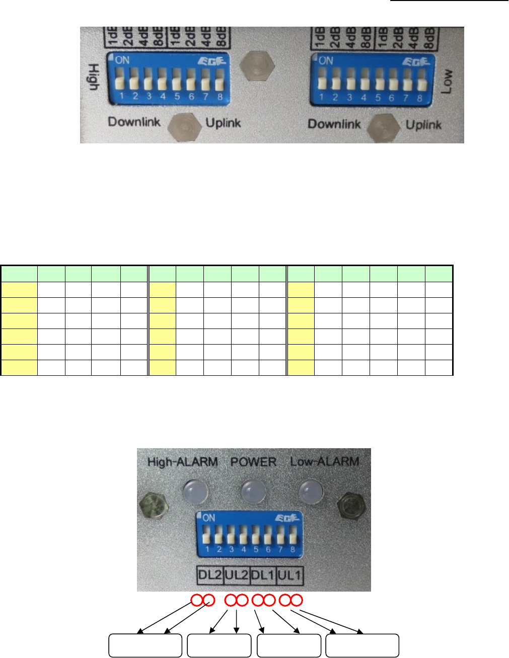
For F15B-CP-M:
Turn ON the dip switches to reduce gain as follows:
Put ON a pair of switches for a total of 15dB reduction in gain.
(DL1 & UL1 – Alarm Low) – For 800MHz or 900 MHz Band
(DL2 & UL2 – Alarm High) – For 1700, 1800, 1900 & 2100 MHz Band
10dB 5dB 10dB 5dB 10dB 5dB 10dB 5dB
User Manual
- 20 -
DIP switch downlink attenuation setting:
Att 1 2
0 dB off off
5 dB ON off
10 dB off ON
15dB ON ON
DIP switch uplink attenuation setting:
Att 3 4
0 dB off off
5 dB ON off
10 dB off ON
15dB ON ON
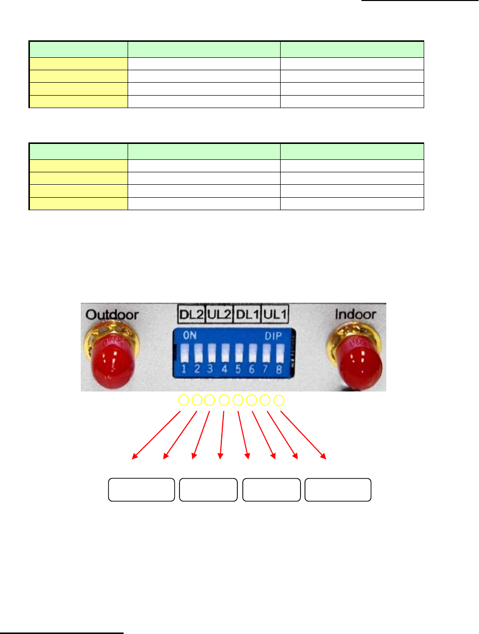
For F15B-CP:
Turn ON the dip switches to reduce gain as follows:
Put ON a pair of switches for a total of 15dB reduction in gain.
(DL1 & UL1 – Alarm Low) – For 800MHz or 900 MHz Band
(DL2 & UL2 – Alarm High) – For 1700, 1800, 1900 & 2100 MHz Band
Remark: In single system, there is only one system could be set.
9.3.3. Booster Commissioning
z Downlink gain setting
First the alarm LED only indicates the downlink input power level, here we use color of Alarm LED
to adjust the gain of the Booster. Alarm LED color must remain green. As for the downlink working
performance, it is a good working point that Alarm LED maintains “Green” color with the intention of turning
orange; here we refer as “edge point”. At this time, downlink output power and coverage effect are stable.
10dB 5dB 10dB 5dB 10dB 5dB 10dB 5dB

User Manual
- 21 -
And the equipment must be as far as possible away from overloading status of “red” (the equipment would
hold higher interference and depression ability at this stage). So we shall try our best to set the equipment
near “edge point” of green and intention of turning orange during engineering.
z Setting of “edge point”:
Switch on the power supply after connection with donor antenna and server antenna, and observe
ALARM LED.
If it shines “orange”, use 1dB as step to reduce the gain until “green” turns on, then increase the gain
1~3dB attenuation value until “orange” starts to turn on, then brings back 1~2dB till “green” is on, then
fix the gain and the Booster’s downlink output power reaches the perfect status.
If it shines “green” then,
Please check coverage effect firstly, if the coverage effect is good, the engineering has reached
expecting target, thus there is no need to do anything.
To check whether the attenuation value has been set, if it is, use 1dB as step to increase gain until
the “orange” turns on, then brings back 1~2dB till “green” is on again , then the Booster’s downlink
output power reaches the perfect status.
But if attenuation has not been set, it indicates that the input power is not strong enough to let the
Booster reach its good coverage.
If the coverage effect is not good, the donor antenna should be adjusted to get stronger input signal.
It is recommended that one person shall check the coverage effect inside the building when the
other person is trying to adjust the antenna or the Booster. At this stage, please make sure “Orange”
color will not be generated by self oscillation. Please take off the server antenna to check if it is self
oscillation or not: if the Orange turns to be green, it is self oscillation; if it stays as Orange, it is not
self oscillation. Please follow steps in other page to turn Orange to be Green.
z Uplink gain setting
Standard: uplink attenuation values =downlink attenuation values
Remark: Avoid putting more than a 5dB difference between the Uplink and Downlink. And Uplink gain must
be equal to or less than Downlink gain, it can’t be more in order to avoid interference with mobile network.
User Manual
- 22 -
9.4. System Test
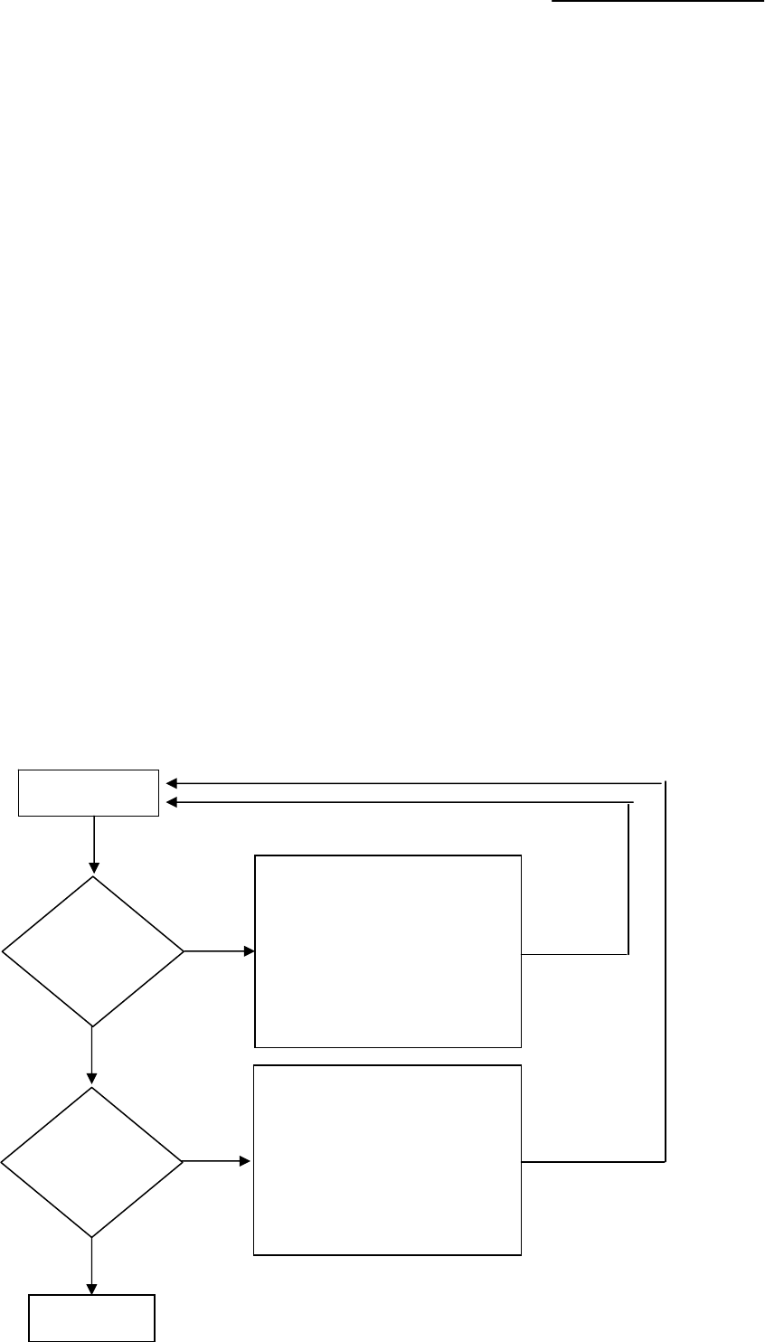
9.4.1. Check whether the coverage is good
1) Have a test with mobile phone or data card (engineering mobile phone is preferred). If the signals in most
areas have not been improved, please check below again:
The weak input signal leads to the low output power. Change the direction of donor antenna or its
installation position or replace donor antenna with higher gain antenna to increase input signal
power level.
Check whether it is necessary to add more server antennas since barriers block the signal
penetration, also check whether the Booster’s power is enough; please install more server
antennas or replace with a Booster of higher power level.
2) If the signals in small part of the areas have not been improved, please check below:
Check whether the service antenna is installed correctly or not, you may try to move the antenna
location to improve coverage.
Check if it is necessary to adjust the direction of the sever antenna.
Check whether it is necessary to add one or more antenna to enhance the coverage of special
areas.
Test
1) Move service antenna
2) Increase the number of
service antennas
3) Reduce the attenuation
values
4) Increase the output
Yes
Completion
Yes
No
1) Move service antenna
2) Increase the number of
service antenna
3) Reduce the attenuation
values
4) Increase the output power
No
Check the
signal
Strength if fit
Check call
quality

User Manual
- 23 -
Remark:
Reduce the attenuation values*---at the same time must ensure the isolation
Increase the output power* ---recommended ways: adjust the donor antenna direction /
location, or replace with higher gain antenna to increase input signal strength.
9.4.2. Booster can not communicate in Power-ON status
1) The power is on but it has a signal fluctuation or a flash signal. The phone call can not be achieved.
It shall be caused by the insufficient isolation between donor antenna and serve antenna.
Please take below measures:
¾ Firstly check whether the alarm LED is orange. The orange light shows the insufficient isolation.
¾ Secondly adjust the antennas’ directions or locations or enlarge the distance between them.
¾ Thirdly reduce the Booster’s gain by ATT DIP if the above methods don’t work.
The following measures can also be tried:
¾ Use the roof of the building to enlarge the isolation (Please try to place the donor antenna and
server antenna in different floors).
¾ Use some obstacles (Such as wall).
2) The Booster’s power is on but the phone is not connected into the network and still can not
communicate.
¾ Reason 1: There are loose or wrong connections in the Booster system.
Solution: Please try to fasten the connections between the different parts of the system.
¾ Reason 2: The signals received by donor antenna of other operators nearby are too strong. (For
example, the other operators’ signals are 10 dB stronger than the needed signals.)
Solution 1: Change the direction of donor antenna or its installation position, so that the gap of
signal strength is reduced between operators.
Solution 2: Use barriers (like buildings) to block signals of other operators.

User Manual
- 24 -
IC STATEMENT
Operation is subject to the following two conditions:
(1) This device may not cause interference, and
(2) This device must accept any interference, including interference that may cause undesired operation of the
device.
Le présent appareil est conforme aux CNR d'Industrie Canada applicables aux appareils radio exempts de
licence.
L'exploitation est autorisée aux deux conditions suivantes :
(1) l'appareil ne doit pas produire de brouillage, et
(2) l'utilisateur de l'appareil doit accepter tout brouillage radioélectrique subi, même si le brouillage est
susceptible d'en compromettre le fonctionnement.
The Manufacturer's rated output power of this equipment is for single carrier operation.
For situations when multiple carrier signals are present,the rating would have to be reduced by 3.5 dB,
especially where the output signal is re-radiated and can cause interference to adjacent band users. This
power reduction is to be by means of input power or gain reduction and not by an attenuator at the output
of the device.
IC Radiation Exposure Statement
This equipment complies with FCC radiation exposure limits set forth for an uncontrolled environment. This
equipment should be installed and operated with minimum distances 20cm between the radiator include antenna &
your body
FCC Statement
1. This device complies with Part 15 of the FCC Rules. Operation is subject to the following two conditions:
(1) This device may not cause harmful interference.
(2) This device must accept any interference received, including interference that may cause undesired operation.
2. Changes or modifications not expressly approved by the party responsible for compliance could void the user's
authority to operate the equipment.
NOTE:
This equipment has been tested and found to comply with the limits for a Class B digital device, pursuant to Part 15
of the FCC Rules.
These limits are designed to provide reasonable protection against harmful interference in a residential installation.
This equipment generates uses and can radiate radio frequency energy and, if not installed and used in accordance
with the instructions, may cause harmful interference to radio communications. However, there is no guarantee
that interference will not occur in a particular installation. If this equipment does cause harmful interference to
radio or television reception, which can be determined by turning the equipment off and on, the user is encouraged
to try to correct the interference by one or more of the following measures:
Reorient or relocate the receiving antenna.
Increase the separation between the equipment and receiver.
Connect the equipment into an outlet on a circuit different from that to which the receiver is connected.
Consult the dealer or an experienced radio/TV technician for help.
FCC Radiation Exposure Statement
This equipment complies with FCC radiation exposure limits set forth for an
uncontrolled environment. This equipment should be installed and operated with
Minimum distances 20cm between the radiator include antenna & your body.
---------------------------------------------------------------End---------------------------------------------------------