HUAC F20G-5S-LCD Quint Band LCD Signal Booster User Manual
SHENZHEN HUAPTEC CO., LTD Quint Band LCD Signal Booster Users Manual
UserManual.wiki
>
HUAC
>
F20G 5S LCD User Manual
Users Manual
Navigation menu
Upload a User Manual
Namespaces
Wiki Guide
HTML
PDF
Info
Views
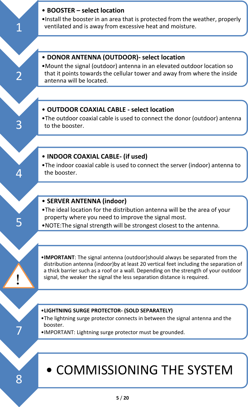
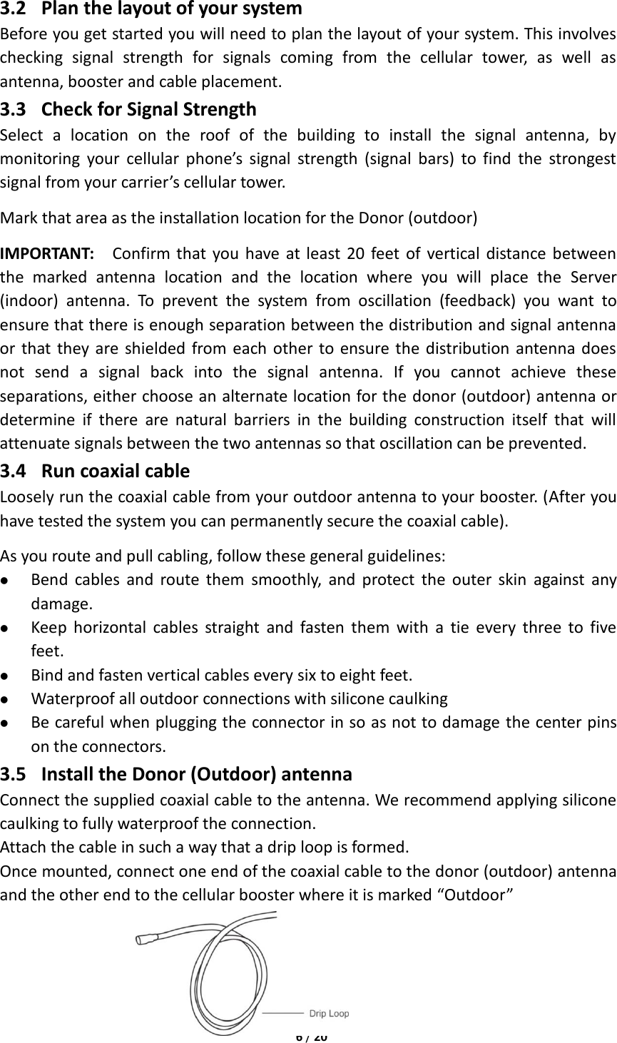
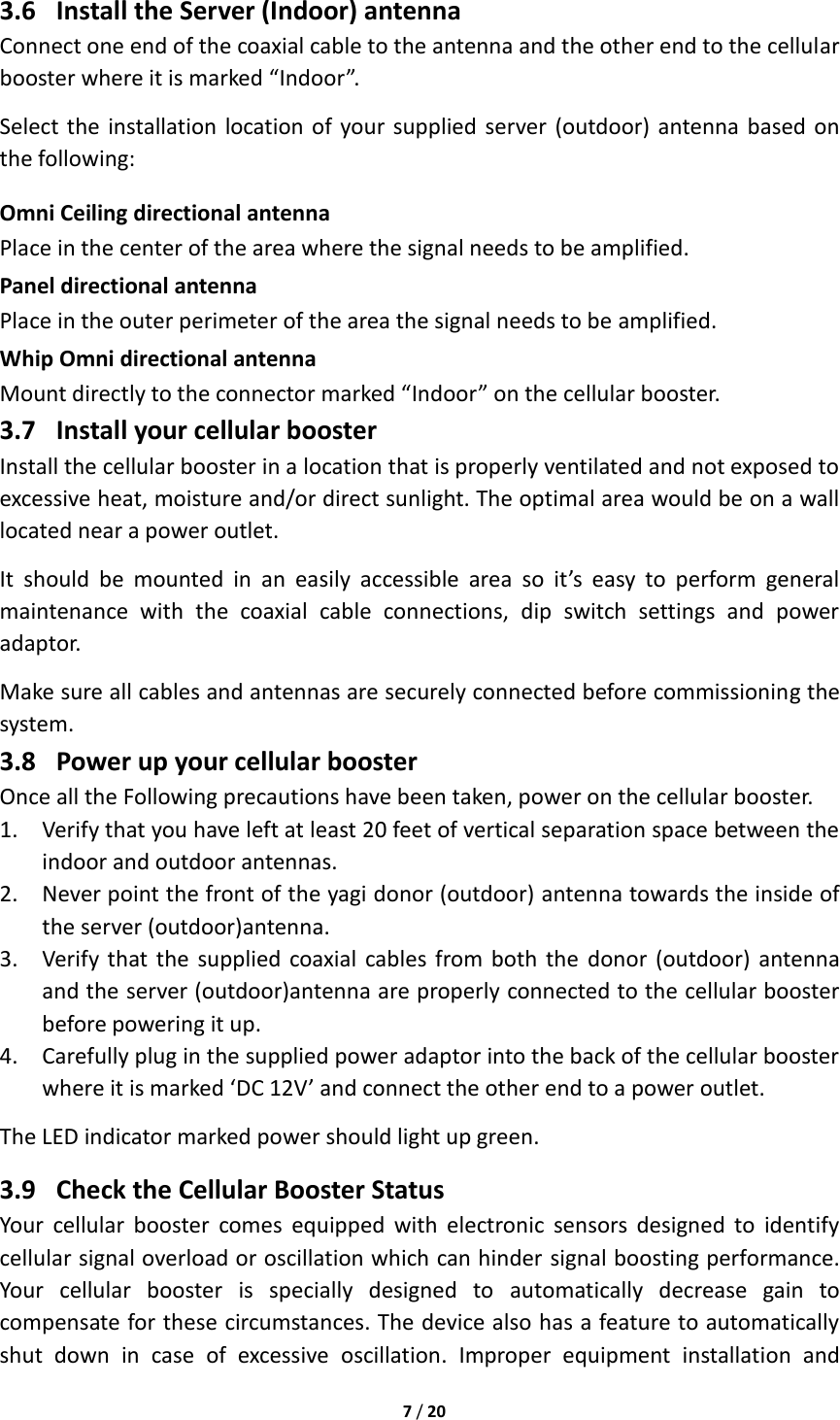
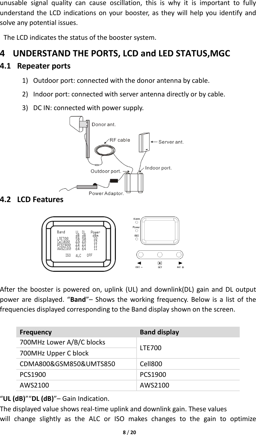
User Manual
Discussion / Help
Navigation